Article

Image-Based Histological Evaluation of Scaffold-Free 3D Osteoblast Cultures

1
Department of Orthopaedics and Sportsorthopaedics, Klinikum rechts der Isar, Technical University of Munich, Ismaninger Strasse 22, 81675 Munich, Germany
2
Chair of Non-Destructive Testing, Centre for Building Materials, Technical University of Munich, Baumbachstrasse 7, 81245 Munich, Germany
3
Institute of Health and Biomedical Innovation, Queensland University of Technology, 60 Musk Avenue, Kelvin Grove 4059, Australia
*
Author to whom correspondence should be addressed.
J. Funct. Morphol. Kinesiol. 2017, 2(4), 42; https://doi.org/10.3390/jfmk2040042
Submission received: 31 October 2017 / Revised: 20 November 2017 / Accepted: 20 November 2017 / Published: 24 November 2017

Abstract

:
The analysis of tissue network characteristics and cell distribution using histological methods is widely used. However, image analysis still relies on manual evaluation methods, known as semi-quantitative analysis, which are time-consuming and to a certain degree user-specific. For this reason, automated imaging processing methods have an enormous potential to increase sample processing and reduce the variation that is caused by a user-specific evaluation. This work demonstrates the feasibility of using a semi-automated image analysis process based on the open source software framework ImageJ and the plug-in Angiogenesis Analyzer to evaluate the quantitative degree of tissue damage within 3D cell constructs after mechanical loading. Within a proof-of-concept study, the semi-automated approach was applied to calculate the Node-to-Free Ratio (N/F-Ratio) and perform a strut analysis for histological evaluation of mechanically compressed samples of human osteoblast-derived 3D constructs. The N/F-Ratio revealed a median value of 1.29 for the control, whereas the values for the mechanically compressed samples decreased to 0.97 for 20% compression, 0.85 for 40%, and 0.86 for 60%. The strut analysis indicated a decrease of the connected branches with increasing compression rate. The newly developed and time-saving processing workflow was successfully established and can be carried out using available, open source software solutions.

Graphical Abstract

1. Introduction

Histology is a common analyzing technique using a light microscope or electron microscope to study cell distribution and tissue characteristic on cross sections which are stained to highlight structures or molecules [1,2,3]. Within the field of cellular biology, the process of staining biological tissue samples is widely used to investigate cellular interactions or structural changes using selected dyes which bind specifically to a proposed biological substance due to different affinities [4,5]. After the staining procedure, imaging techniques are carried out for the acquisition of the image data followed by the image analysis and evaluation process, known as histomorphometry [6]. Histomorphometry is defined as the quantitative measurement of the structure and organization of biological substances [7], and is often performed for the evaluation of the structural pattern of human trabecular bone [8].
Although the quantity and complexity of image data are increasing, there are limited efforts on the development of more comprehensive, user-friendly, and interoperable software solutions in the field of histomorphometry [9]. A commonly and widely used method in the field of histomorphometry is still the semi-quantitative evaluation method of the image data based on manual scoring systems—informally also called “eyeballing” [10,11]. Manually-driven evaluation methods such as the semi-quantitative evaluation are potentially subjected to significant intra- and interobserver variability which could lead to reproducibility issues during the image analysis process. Besides that, semi-quantitative evaluations result in time-consuming procedures compared to fully automated image processing; thus manually-driven evaluations are limited in term of high-throughput capability. Finally, subtleties within the image data cannot be observed with the human eye and potential hidden information is not being investigated. For this reason, automated image processing can provide a beneficial approach for histomorphometry.
Since high-quality images as well as hardware with high-throughput capabilities are available for imaging solutions, the bioimage informatics community is also strongly developing more sophisticated software solutions capable of obtaining information-rich measurements from acquired image data in an accurate and reproducible manner [12,13]. Besides a range of commercial software solutions [14], open-source software packages—such as Fiji/ImageJ [15], Tango [16], Icy [17], and CellProfiler [18]—have been reported over the last years. For a comprehensive review on biological imaging software tools and data-analysis strategies for image-based cell profiling, the authors refer to the work of Eliceiri et al. [19] and Caicedo et al. [20]. Although sophisticated software tools with deep learning [21] and machine learning capabilities [22] have been developed for cell cycle analysis for imaging flow cytometry [13], morphological profiling using multiplexed fluorescent dyes [23], and microvascular network characteristics [24], only very few computer-assisted methods are reported for histomorphometry. Recently reported image analysis work is still relying on commercial software solutions which are costly, not freely available, and do not use an open source software approach. For example, Adobe Photoshop® (Adobe, San Jose, CA, USA, CC 2017.1.1) offers great capabilities for image editing and it is often used for histomorphometry [25]; however, it is very expensive and does not provide the flexibility and high-throughput capability for efficient histological evaluation. The usage of other commercial software packages such as OsteoMeasure™ (Osteometrics, Atlanta, GA, USA) [26] and Bioquant Osteo (Bioquant Image Analysis, Nashville, TN, USA) [27] is limited as either specific imaging hardware is required or no open source code is available which can be adapted to the user requirements. For this reason, the open source package ImageJ attracted a wide and interdisciplinary user-base, resulting in a large number of plug-ins which made ImageJ an extensive toolbox for image analysis. Recent trends have already highlighted the great benefit of automated methods for histomorphometry using open-source software solutions [28,29].
Here, we present an integrated approach for histological evaluation based on the open-source software framework ImageJ and the plug-in Angiogenesis Analyzer to characterize the matrix of scaffold-free 3D human-osteoblast derived cell cultures. Semi-automated image evaluation was applied to investigate the quantitative degree of tissue damage within the 3D cell constructs using the established methods N/F-Ratio and strut analysis. In contrast to real-time evaluation from tissue sections—referred to as automated or live image evaluation—semi-automated image evaluation is performed on archived images to determine histomorphometric parameters [27]. The reported proof-of-concept study demonstrates a cost-effective alternative to commercially available software solutions for the evaluation of stained tissue. Due to the open-source character, the algorithms can be adapted to specific user requirements. We provide a detailed description of the semi-automated image evaluation process, its feasibility of the image processing with successful feature identification, and a quantitative network connectivity analysis. The novelty of this work comes from (1) the integration of image evaluation processes for the analysis of network connectivity characteristics of stained tissue for 3D cell culture applications; and (2) the capability of the described and established workflow as a toolbox for performing quantitative measurements in histomorphometry. The reported study successfully demonstrated the benefits of the automated image analysis approach with an integrated data analysis workflow for histological evaluation of stained slices derived from 3D tissue constructs.

2. Materials and Methods

2.1. Ethical Statement

The ethics committee of the Medical Faculty at Technical University of Munich (TUM, Munich, Germany) has approved all research involving human participants and all patients provided their written consent to participate in this study (ethics application number 1307/05).

2.2. Cell Culture

Primary human osteoblasts were obtained from the trabecular bone of the femoral head after a surgical procedure according to the established protocol [30]. Cells were cultured in an incubator (Heracell 150 incubator, Thermo Fisher Scientific, Waltham, MA, USA) at 37 °C with 5% CO2 in 175 cm2 cell culture flasks (BD Falcon, Franklin Lakes, NJ, USA). Proliferation medium constituted calcium-free Dulbeccos modified Eagle’s medium (P04-01501, PAN Biotech, Aidenbach, Germany) with 15% (v/v) fetal bovine serum (FBS) (S0115, Merck Millipore, Darmstadt, Germany), 0.8% (v/v) MEM vitamin mix (M6895, Merck Millipore), 2 nM/l-glutamine (59202C, Merck Millipore), and 100 mg/L Primocin (ant-pm-2, Invivogen, Toulouse, France). For osteogenic medium, 2.8 µM/l-ascorbic acid (A5960, Merck Millipore) and 10 nM dexamethasone (D4902, Merck Millipore) were added to the base medium. Media was changed bi-weekly. All work steps were carried out under sterile working conditions in a sterile safety cabinet.
For 3D cell culture, cells were allowed to reach confluence. Formation of a cell multilayer was observed after cultivation for several weeks. The cell multilayer was detached using a plastic cell scraper to induce random folding of the cell multilayer into tissue-like structures, referred to as histoids [31]. Proliferation medium was changed weekly. After cultivation for 38–42 weeks, the biomechanical characterization was performed to characterize the effect on the histoid after a single loading step at different strain levels.

2.3. Biomechanical Loading

All loading tests were performed by a custom-made uniaxial test system with calibrated sensors for (i) external displacement measurements after the mechanical gearing (LIC-4007, ±0.1 µm resolution over a length of 50 mm, Dr. Johannes Heidenhain GmbH, Traunreut, Germany) and (ii) force at the compression plate/indenter (Type 8432-20, max. ±20 N, class 0.05, Burster GmbH, Gernsbach, Germany) [32]. A single compression step was applied to each cylindrical sample (diameter of 6 mm) ranging from 20%, 40%, 60% of the original tissue height, and 0% for the control group. The tissue height was measured by moving the tared compression plate (with respect to the bottom plate) towards the specimen under optical control using two microscopic cameras that were placed perpendicular to each other and also orthogonal to the loading axis (DigiMicro 2.0, dnt, Dietzenbach, Germany). All tests were performed in an unconfined compression setup. The specimen chamber was filled up with the described cell culture medium and the compression rate was performed by a normalized speed of 0.5 s per selected strain step, followed by the removal of the strain step within the same duration of loading.

2.4. Van-Gieson Staining

Samples were sectioned (cryostat CM-3050S Leica Microsystems GmbH, Wetzlar, Germany), and stored at −20 °C. The Van Gieson staining solution was produced according to the standard protocol. Slides were thawed, air dried, and fixated with methanol-acetone (1:1). Then, slides were rehydrated in 0.1 molar Phosphate Buffered Saline (PBS) for 5 min followed by nuclear staining in Weigert’s solution for 7 min. After a 5 s rinse in distilled H2O, sections were rinsed under running tap water for 10 min. Specific tissue staining was performed by applying the Van Gieson staining solution for 2 min. Afterwards, sections were rinsed again in distilled H2O and dehydrated in alcohols, cleared, and mounted with Eukitt.

2.5. Semi-Automated Image Evaluation Process

To quantitatively measure and evaluate the degree of tissue damage after biomechanical compression testing, the semi-automated image analysis process was implemented in this study. The workflow is comprised of (1) feature definition, (2) definition of regions-of-interest (ROI), (3) image acquisition, (4) image segmentation, (5) feature identification, and (6) analysis, and is described in detail in the following sections.

2.5.1. Feature Definition

The image analysis of the structural pattern is based on the measurement of network characteristics and elements, which will be defined in this paragraph. The definition and abbreviations are based on the introduction of the Histomorphometry Nomenclature Committee of the American Society for Bone and Mineral Research (ASBMR, Washington, DC, USA) [33]. “Nodes” (Nd) are defined as junctions of three or more struts, whereas endpoints with only one junction are referred as “Terminus” (Tm). The absolute number of nodes and termini is defined as “Number-of-Nodes” (N.Nd) and “Number-of-Termini” (N.Tm), respectively. Furthermore, different strut types can be evaluated within a structure. The total connection length from all connections, branches, and isolated branches is the “Total-Strut-Length” (TSL). The total length of all connections between two nodes is defined as “Node-to-Node-Strut-Length” (Nd.Nd), between nodes and termini is “Node-to-Terminus-Strut-Length” (Nd.Tm), and between two termini is “Terminus-to-Terminus-Strut-Length” (Tm.Tm). The extracellular matrix (ECM) network characteristics is described as the connectivity, defined as an index for the typology of the various elements (Nd and Tm) and connecting segments (different types of struts such as Nd.Nd) [7]. From a quantitative perspective, connectivity in this study is defined as the degree to which the investigated structure is multiply connected described by the various links among the nodes [34].

2.5.2. Definition of Regions-of-Interest

From each sample, one section from the upper area, two sections from the middle, and one section from the lower area were stained (Figure 1a). Four regions per section were subsequently histomorphometrically evaluated: two edge regions and two central regions (Figure 1b). The results of the semi-quantitative and computer-assisted method were based on the evaluation of two sample cylinders (n = 2) for the control group and within the 20% compression group, whereas three sample cylinders (n = 3) were investigated for the 40% and 60% compression group. For each sample cylinder, 16 ROIs were evaluated, resulting in 32 ROIs for the control group and the 20% compression group, and 48 ROIs for the 40% and 60% compression group.

2.5.3. Image Acquisition

Phase contrast images of the stained matrix were captured using the phase-contrast microscope Axiovert 40CFL (Carl Zeiss AG, Oberkochen, Germany) connected to a light camera (Axiocam ICc1, Carl Zeiss AG). Files were saved using the ZEISS imaging software (Axion Vision 4.2) as CZI files and then exported as TIFF files. Images were taken at 200× magnification. The images had a resolution of 1300 × 1300 pixels, resulting in a size of 691.3 × 547.7 µm at a scale of 0.532 µm per pixel.

2.5.4. Image Segmentation

To reduce the loss of image information, a two-stage conversion process was applied using ImageJ. The first processing step contained the binary conversion of the digital images using an iterative method based on the ISODATA algorithm [35]. The chosen algorithm processed the image into object and background pixels by setting an initial threshold and then calculating the average threshold intensity of the gray value both at and below the threshold as well as above the threshold. Next, the average value is calculated from the intensity of the object and background pixels and compared with the selected threshold value. The threshold value is then increased or decreased until the average value is equal to the threshold value. Afterwards, images were converted into 8 bit.
The second processing step was based on the principle of topological skeletons and removed pixels from the boarder of an object in a binary image to a one-pixel-wide-line, called the “skeleton”. To perform this processing step, the “Skeletonize” function was used as an algorithm applying a predefined lookup table for pixel analysis [36].

2.5.5. Feature Identification

The Angiogenesis Analyzer, an ImageJ plug-in created by Gilles Carpentier [37] and developed for the analysis of cellular networks such as endothelial network formation [38,39], was integrated for the evaluation of the connectivity within this study. Briefly, a skeleton analysis is performed where pixels are evaluated based on their neighboring pixels and assigned into the pre-defined elements such Tm and Nd. Then, a branch analysis groups the elements into the strut categories like Tm.Tm, Nd.Tm, and Nd.Nd. Finally, the data output was carried out on excel spreadsheets.

2.5.6. Analysis

Analysis was performed using the N/F-Ratio and the strut analysis; both methods were introduced for the analysis of 2D structural patterns of the trabecular bone [40]. The N/F-Ratio is derived from the quotient of N.Nd and N.Tm, and describes the degree of the network connectivity (Equation (1)). The higher the N/F-Ratio, the greater the network connectivity within the evaluated structure [41]. Based on the strut analysis, the total length of each strut type is calculated and depicted as a percentage to the TLS (Equations (2)–(4)) [7]. The N/F-Ratio and Nd.Nd are positively related to network connectivity, whereas Tm.Tm is inversely related [41].
N/F-Ratio = N.Nd/N.Tm
Nd.Nd-to-TLS-Ratio = Nd.Nd/TLS
Nd.Tm-to-TLS-Ratio = Nd.Tm/TLS
Tm.Tm-to-TLS-Ratio = Tm.Tm/TLS

3. Results

3.1. Demonstrating the Feasibility of the Image Processing and the Feature Identification

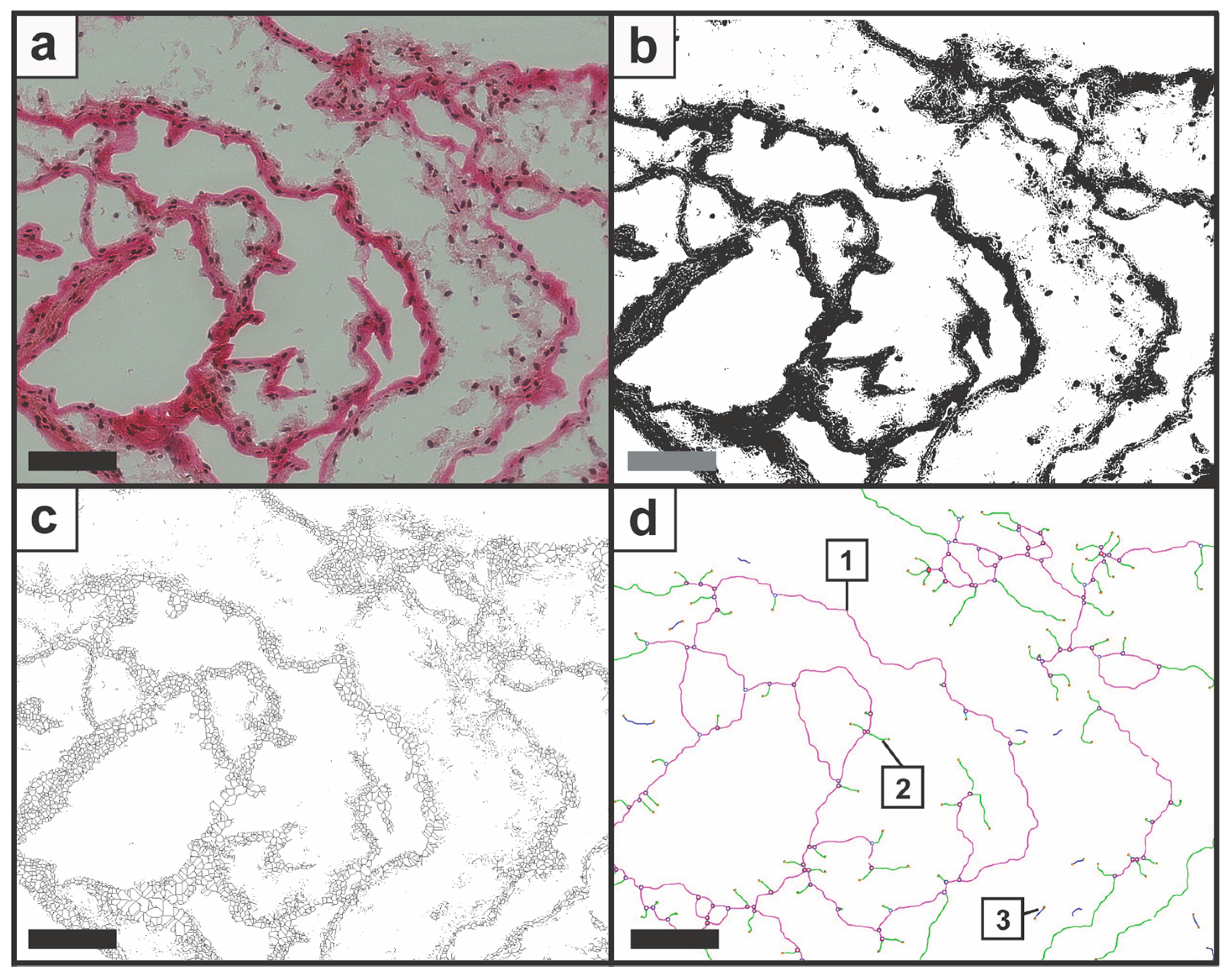
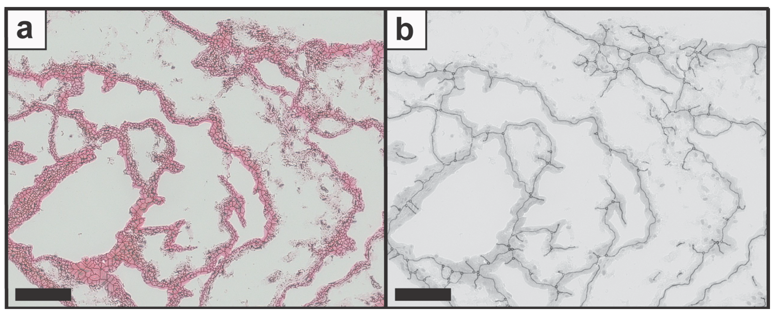
Initial experiments were conducted to assess the performance of the image processing steps and the feasibility of feature identification with candidate images. Therefore, candidate image data were imported as TIFF files into ImageJ (Figure 2a) and processed with the developed approach. After the binary image was created (Figure 2b), the image was processed into a skeletal structure (Figure 2c) followed by the analysis with the plug-in Angiogenesis Analyzer. The analyzed structure was exported in a TIFF format with the colored elements (Figure 2d). In addition to the image data, a CSV file with the determined numbers was created and saved automatically. Furthermore, the plug-in allowed the selection and display of single elements by the “Get Maps of Selection”, such as “Map of Segments” for Nd.Nd or “Map of Extremities” for Tm (Figure S1). To evaluate the identification quality of the original with the processed images, the skeleton (Figure 3a) and then the network structure image (Figure 3b) were aligned with the original image. The overlap of the skeleton image displayed a uniform match with the original data; however, bright areas were not identified and therefore not displayed. When the network structure image was overlapped with the original image, a high degree of overlay was observed throughout the generated data set.

3.2. Determination of Node-to-Free-Ratio and Strut Analysis

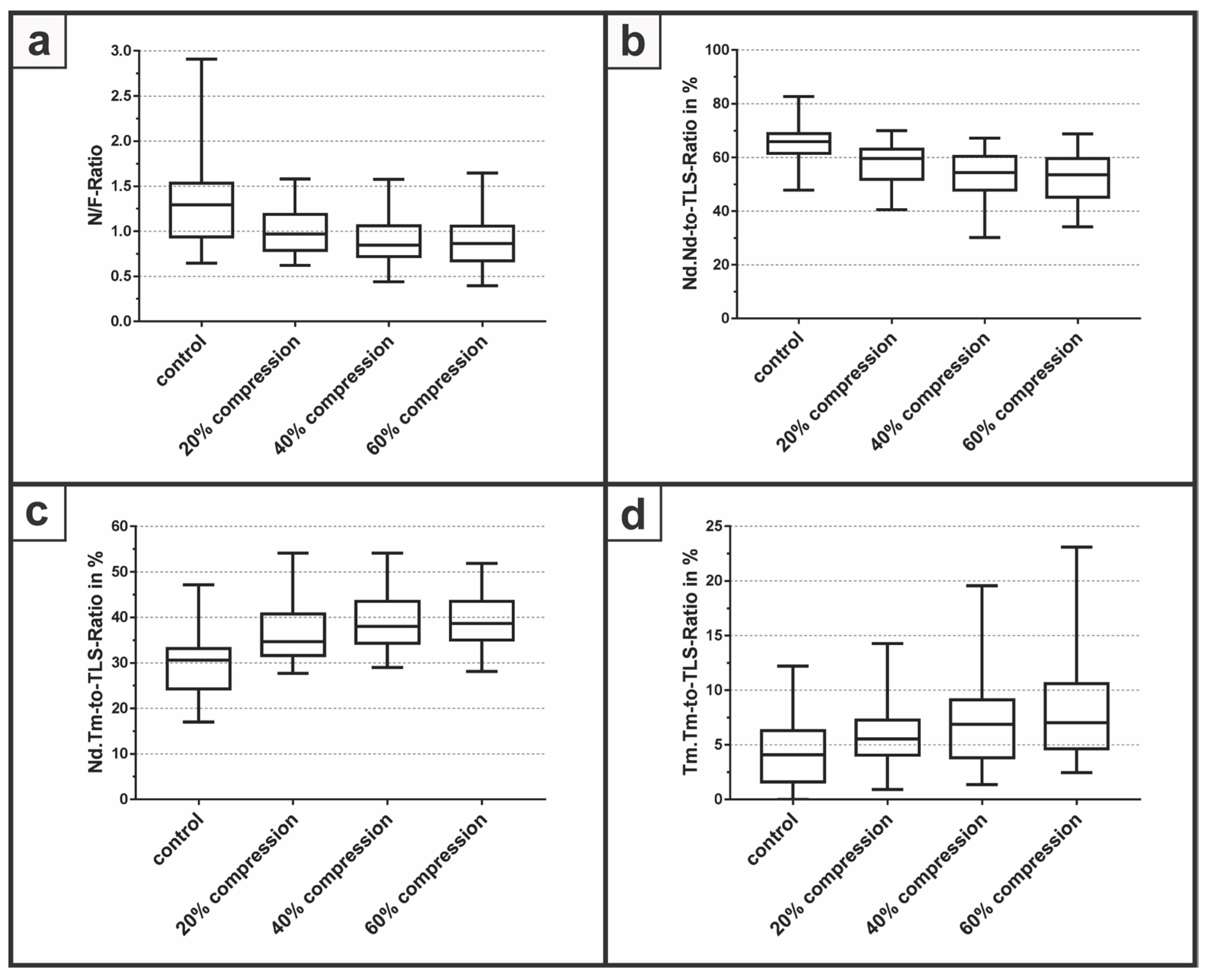
To determine the ability to evaluate the quantitative degree of tissue damage within 3D cell constructs, the N/F-Ratio (Figure 4a) and a strut analysis was performed presenting the Nd.Nd-to-TLS-Ratio (Figure 4b), the Nd.Tm-to-TLS-Ratio (Figure 4c), and the Tm.Tm-to-TLS-Ratio (Figure 4d) within a proof-of-concept study. Therefore, samples with a diameter of 6 mm were mechanically compressed with a compression rate of 20%, 40%, and 60%, subsequently stained, and histologically evaluated with the described image processing workflow.
The N/F-Ratio revealed a median of 1.29 with a minimum of 0.65 and a maximum of 2.91 for the control group without a compression of the samples. At the compression of 20%, the median decreased to 0.97 with a minimum of 0.62 and a maximum of 1.58. The median for a compression of 40% was 0.85 with a minimum of 0.44 and a maximum of 1.58, whereas at 60% compression, the median had the lowest value at 0.86 with a minimum of 0.40 and a maximum of 1.64. For the Nd.Nd-to-TLS-Ratio, the control group yielded the highest median with 65.9% for all groups compared to 59.6%, 54.4% and 53.6% for a compression rate of 20%, 40% and 60%, respectively. The Nd.Tm-to-TLS-Ratio revealed the lowest median with 30.6% for the control group. With increasing compression rates of 20%, 40% and 60%, the median increased to 34.6%, 38.0% and 38.7%, respectively. Finally, the Tm.Tm-to-TLS-Ratio demonstrated a median of 4.1% for the control group compared to a median of 5.5%, 6.9% and 7% for compression rates of 20%, 40%, and 60% respectively. However, due to the low number of independent samples, a statistical evaluation, for example one-way ANOVA, was not performed within this feasibility study.

4. Discussion

The presented study aims to demonstrate an alternative approach to process histological stained images and evaluate the degree of connectivity by establishing a workflow with ImageJ and the plug-in Angiogenesis Analyzer. The image processing allows feature identification of elements for further calculation of the N/F-Ratio and strut analysis in order to evaluate the quantitative degree of tissue damage within 3D cell constructs. Within a proof-of-concept study, the feasibility of the semi-automated image analysis process was demonstrated by the histological evaluation of mechanically compressed samples. Both processing and analysis were performed on archived images, resulting in a semi-automated evaluation method for pre-defined histomorphometric parameters.
The described method was transferred into a standard operation procedure document and now acts as a rapid evaluation tool, resulting in a substantial decrease in time required for the analysis during histological evaluation. In contrast to other semi-quantitative evaluation methods, the results obtained by using the presented image analysis process are non-subjective and highly reproducible. The semi-automated image analysis process is also independent of a specific operating system and there is no extensive computing power necessary. The open-source character of ImageJ and the plug-in allows further code development for specialized applications and enhanced feature identifications. However, the presented workflow is still composed of subsequent steps and cannot be performed as a single analysis task yet. Focusing on user-friendly software, more efforts are needed to design an intuitive interface providing also help and documentation throughout the processing. The combination of the open-source character with powerful software libraries enabled the bioinformatics community to integrate custom image-processing pipelines [15] and also improved the current ImageJ user interface to increase the software usability [9]. Established methods were implemented for the analysis and evaluation of two-dimensional structural patterns, describing the degree of connectivity and thereby allowing the quantification of tissue damage. The N/F-Ratio and the strut analysis present powerful tools in the study of microarchitecture, based on primary measurements such as width, number, or spatial organization [7]. Moreover, the usage of standardized definitions and abbreviations based on the ASBMR facilitates the communication with non-histomorphometrists [42] due to self-explanatory and descriptive names [33].
Although the overlay of the original image with the network structure image presented a general overlap of most areas, areas with false segmentation and feature identification demonstrate limitations of the described image processing workflow. Within dense and large zones, unnecessary struts were added as a cluster of branches and connections (Figure 5a,d). The false classification may result from the binary segmentation and the skeleton structure, where information gets lost. Furthermore, transitions, which are not clearly colored, were not adequately recognized (Figure 5b,e) and insufficient identification of structures at the image edge was observed throughout the images (Figure 5c,f). By means of these false identifications, slightly biased N.Nd as well as N.Tm were used for the calculation of the N/F-Ratio and the strut analysis. The binary processing resulted in a decrease of detailed information about small, low-contrast transitions and large-scale colored structures which may result in incorrect analysis. This error source could possibly be minimized by using stains with more intense colors and appropriate contrast settings.

4.1. Future Work

Based on the presented approach, more ROIs can be integrated into the feature analysis, which would increase the study significance and would also enable a comparison between boundary and center areas of sections. To evaluate the developed process, the presented workflow can be compared with commercial software solutions such as Bioquant Osteo regarding image processing, flexibility, and output [27]. To enhance the segmentation quality of stained matrix and feature identification, future effort should focus on code development for this purpose.

4.2. Study Limitations

Since histoids from osteoblasts with primary cells were used in this study, 3D tissue constructs are not homogeneous in behavior and composition. Furthermore, the geometric volumes of the constructs are not constant and vary widely. Consequently, this inhomogeneous composition as well as the selected punching position must be considered for the comparability of the samples throughout the study. Therefore, a general statement about the damage analysis of tissue constructs with a semi-automated image analysis process after mechanical stress is only possible to a limited extent. In addition, only a small number of samples were available for this pilot study, since primary cells were limited and histoids were culture for 38–42 weeks. Therefore, presented and discussed observations rely on available histoids, and could deviate strongly with other samples. The section selection for quantitative histomorphometry are candidate sections of the entire sample and do not represent the 3D architecture of the histoid. Preliminary treatments, such as cryostat cuts, staining methods, etc., may lead to matrix damage. These alterations cannot be clearly defined, since these steps must also be carried out for the control group. In order to improve the statistical significance of this study, further biomechanical studies with a higher donor number of the primary cells could be carried out. In the discussion and interpretation, the punching process to harvest a standardized geometry from the histoids must also be taken into account. Through the punching process, structural relationships within the tissue structures might get changed or be destroyed.

5. Conclusions

Histomorphometry is an important element in the image analysis and evaluation process where a quantitative measurement of the structure and organization is performed to assess the microarchitecture with meaningful feature identification such as the number of connecting nodes. Herein, we present a semi-automated approach based on the free and open-source software package ImageJ and the plug-in Angiogenesis Analyzer, resulting in a flexible solution which can be optimized to meet manifold user requirements. The feasibility of the image processing and feature identification was successfully demonstrated for candidate sections of human osteoblast-derived 3D cell constructs stained via Van Gieson staining. The capability of the developed approach was tested within a proof-of-concept study to determine and evaluate mechanically compressed samples. The method described in this paper enables an alternative approach for histological evaluation based on a semi-automated image processing and analysis method, resulting in a more reproducible and accurate manner compared to semi-quantitative evaluation methods. Further code development is necessary to enhance feature identification as well as to broaden the potential application range.

Supplementary Materials

The following are available online at www.mdpi.com/2411-5142/2/4/42/s1.

Acknowledgments

The study was supported by the Federal Ministry of Education and Research; Grant number: 0315577C (“Funktionelle Qualitätssicherung von regenerativen Gewebeersatzmaterialien für Knorpel und Meniskus (QuReGe)”). The authors would like to thank Belma Saldamli from the Department of Orthopaedics and Sportsorthopaedics at Technical University Munich for fruitful scientific advice.

Author Contributions

Jutta Tuebel, Christian U. Grosse, Rainer Burgkart conceived and designed the experiments; Sebastian Eggert, Peter Foehr, and Lara Kuntz performed the experiments; Sebastian Eggert, Jutta Tuebel, Peter Foehr, Carmen Marthen analyzed the data; Andreas Obermeier and Carmen Marthen contributed reagents and analysis tools; Sebastian Eggert wrote the paper.

Conflicts of Interest

The authors declare no conflict of interest.

Abbreviation

NdNode
N/F-RatioNode-to-Free-Ratio
Nd.NdNode-to-Node-Strut-Length
Nd.TmNode-to-Terminus-Strut-Length
N.NdNumber-of-Nodes
N.TmNumber-of-Termini
TmTerminus
Tm.TmTerminus-to-Terminus-Strut-Length
TLSTotal-Strut-Length
ROIRegions-of-Interest

References

  1. McCarthy, E.F. The histology of metabolic bone disease. Diagn. Histopathol. 2016, 22, 378–383. [Google Scholar] [CrossRef]
  2. Coleman, R. The long-term contribution of dyes and stains to histology and histopathology. Acta Histochem. 2006, 108, 81–83. [Google Scholar] [CrossRef] [PubMed]
  3. Canfield, P.J.; Hemsley, S. The roles of histology and immunohistology in the investigation of marsupial disease and normal lymphoid tissue. Dev. Comp. Immunol. 2000, 24, 455–471. [Google Scholar] [CrossRef]
  4. Dapson, R.W. Dye-tissue interactions: Mechanisms, quantification and bonding parameters for dyes used in biological staining. Biotech. Histochem. 2005, 80, 49–72. [Google Scholar] [CrossRef] [PubMed]
  5. Scott, J.E. The molecular biology of histochemical staining by cationic phthalocyanin dyes: The design of replacements for Alcian Blue. J. Microsc. 1980, 119, 373–381. [Google Scholar] [CrossRef] [PubMed]
  6. Hunter, D.A.; Moradzadeh, A.; Whitlock, E.L.; Brenner, M.J.; Myckatyn, T.M.; Wei, C.H.; Tung, T.H.H.; Mackinnon, S.E. Binary imaging analysis for comprehensive quantitative histomorphometry of peripheral nerve. J. Neurosci. Methods 2007, 166, 116–124. [Google Scholar] [CrossRef] [PubMed]
  7. Dalle Carbonare, L.; Valenti, M.T.; Bertoldo, F.; Zanatta, M.; Zenari, S.; Realdi, G.; Lo Cascio, V.; Giannini, S. Bone microarchitecture evaluated by histomorphometry. Micron 2005, 36, 609–616. [Google Scholar] [CrossRef] [PubMed]
  8. Hildebrand, T.; Laib, A.; Müller, R.; Dequeker, J.; Rüegsegger, P. Direct three-dimensional morphometric analysis of human cancellous bone: Microstructural data from spine, femur, iliac crest, and calcaneus. J. Bone Miner. Res. 1999, 14, 1167–1174. [Google Scholar] [CrossRef] [PubMed]
  9. Carpenter, A.E.; Kamentsky, L.; Eliceiri, K.W. A call for bioimaging software usability. Nat. Methods 2012, 9, 666–670. [Google Scholar] [CrossRef] [PubMed]
  10. Braun, M.; Kirsten, R.; Rupp, N.J.; Moch, H.; Fend, F.; Wernert, N.; Kristiansen, G.; Perner, S. Quantification of protein expression in cells and cellular subcompartments on immunohistochemical sections using a computer supported image analysis system. Histol. Histopathol. 2013, 28, 605–610. [Google Scholar] [CrossRef] [PubMed]
  11. Deshpande, V.; Zen, Y.; Chan, J.K.; Yi, E.E.; Sato, Y.; Yoshino, T.; Klöppel, G.; Heathcote, J.G.; Khosroshahi, A.; Ferry, J.A.; et al. Consensus statement on the pathology of IgG4-related disease. Mod. Pathol. 2012, 25, 1181–1192. [Google Scholar] [CrossRef] [PubMed]
  12. Meijering, E.; Carpenter, A.E.; Peng, H.; Hamprecht, F.A.; Olivo-Marin, J.-C. Imagining the future of bioimage analysis. Nat. Biotechnol. 2016, 34, 1250–1255. [Google Scholar] [CrossRef] [PubMed]
  13. Blasi, T.; Hennig, H.; Summers, H.D.; Theis, F.J.; Cerveira, J.; Patterson, J.O.; Davies, D.; Filby, A.; Carpenter, A.E.; Rees, P. Label-free cell cycle analysis for high-throughput imaging flow cytometry. Nat. Commun. 2016, 7, 10256. [Google Scholar] [CrossRef] [PubMed]
  14. Li, L.; Zhou, Q.; Voss, T.C.; Quick, K.L.; LaBarbera, D.V. High-throughput imaging: Focusing in on drug discovery in 3D. Methods 2016, 96, 97–102. [Google Scholar] [CrossRef] [PubMed]
  15. Schindelin, J.; Arganda-Carreras, I.; Frise, E.; Kaynig, V.; Longair, M.; Pietzsch, T.; Preibisch, S.; Rueden, C.; Saalfeld, S.; Schmid, B.; et al. Fiji: An open-source platform for biological-image analysis. Nat. Methods 2012, 9, 676–682. [Google Scholar] [CrossRef] [PubMed]
  16. Ollion, J.; Cochennec, J.; Loll, F.; Escudé, C.; Boudier, T. TANGO: A generic tool for high-throughput 3D image analysis for studying nuclear organization. Bioinformatics 2013, 29, 1840–1841. [Google Scholar] [CrossRef] [PubMed]
  17. De Chaumont, F.; Dallongeville, S.; Chenouard, N.; Hervé, N.; Pop, S.; Provoost, T.; Meas-Yedid, V.; Pankajakshan, P.; Lecomte, T.; Le Montagner, Y.; et al. Icy: An open bioimage informatics platform for extended reproducible research. Nat. Methods 2012, 9, 690–696. [Google Scholar] [CrossRef] [PubMed]
  18. Carpenter, A.E.; Jones, T.R.; Lamprecht, M.R.; Clarke, C.; Kang, I.H.; Friman, O.; Guertin, D.A.; Chang, J.H.; Lindquist, R.A.; Moffat, J.; et al. CellProfiler: Image analysis software for identifying and quantifying cell phenotypes. Genome Biol. 2006, 7, R100. [Google Scholar] [CrossRef] [PubMed]
  19. Eliceiri, K.W.; Berthold, M.R.; Goldberg, I.G.; Ibanez, L.; Manjunath, B.S.; Martone, M.E.; Murphy, R.F.; Peng, H.; Plant, A.L.; Roysam, B.; et al. Biological imaging software tools. Nat. Methods 2012, 9, 697–710. [Google Scholar] [CrossRef] [PubMed]
  20. Caicedo, J.C.; Cooper, S.; Heigwer, F.; Warchal, S.; Qiu, P.; Molnar, C.; Vasilevich, A.S.; Barry, J.D.; Bansal, H.S.; Kraus, O.; et al. Data-analysis strategies for image-based cell profiling. Nat. Methods 2017, 14, 849–863. [Google Scholar] [CrossRef] [PubMed]
  21. Eulenberg, P.; Köhler, N.; Blasi, T.; Filby, A.; Carpenter, A.E.; Rees, P.; Theis, F.J.; Wolf, F.A. Reconstructing cell cycle and disease progression using deep learning. Nat. Commun. 2017, 8, 463. [Google Scholar] [CrossRef] [PubMed]
  22. Sommer, C.; Gerlich, D.W. Machine learning in cell biology—Teaching computers to recognize phenotypes. J. Cell Sci. 2013, 126, 5529–5539. [Google Scholar] [CrossRef] [PubMed]
  23. Bray, M.-A.; Singh, S.; Han, H.; Davis, C.T.; Borgeson, B.; Hartland, C.; Kost-Alimova, M.; Gustafsdottir, S.M.; Gibson, C.C.; Carpenter, A.E. Cell Painting, a high-content image-based assay for morphological profiling using multiplexed fluorescent dyes. Nat. Protoc. 2016, 11, 49817. [Google Scholar] [CrossRef] [PubMed]
  24. Morin, K.T.; Carlson, P.D.; Tranquillo, R.T. Automated image analysis programs for the quantification of microvascular network characteristics. Methods 2015, 84, 76–83. [Google Scholar] [CrossRef] [PubMed]
  25. Kontulainen, S.; Liu, D.; Manske, S.; Jamieson, M.; Sievänen, H.; McKay, H. Analyzing cortical bone cross-sectional geometry by peripheral QCT: Comparison with bone histomorphometry. J. Clin. Densitom. 2007, 10, 86–92. [Google Scholar] [CrossRef] [PubMed]
  26. Walker, E.C.; Mcgregor, N.E.; Poulton, I.J.; Pompolo, S.; Allan, E.H.; Quinn, J.M.; Gillespie, M.T.; Martin, T.J.; Sims, N.A. Cardiotrophin-1 is an osteoclast-derived stimulus of bone formation required for normal bone remodeling. J. Bone Miner. Res. 2008, 23, 2025–2032. [Google Scholar] [CrossRef] [PubMed]
  27. Egan, K.P.; Brennan, T.A.; Pignolo, R.J. Bone histomorphometry using free and commonly available software. Histopathology 2012, 61, 1168–1173. [Google Scholar] [CrossRef] [PubMed]
  28. Van’t Hof, R.J.; Rose, L.; Bassonga, E.; Daroszewska, A. Open source software for semi-automated histomorphometry of bone resorption and formation parameters. Bone 2017, 99, 69–79. [Google Scholar] [CrossRef] [PubMed]
  29. Doube, M.; Klosowski, M.M.; Arganda-Carreras, I.; Cordelières, F.P.; Dougherty, R.P.; Jackson, J.S.; Schmid, B.; Hutchinson, J.R.; Shefelbine, S.J. BoneJ: Free and extensible bone image analysis in ImageJ. Bone 2010, 47, 1076–1079. [Google Scholar] [CrossRef] [PubMed]
  30. Aldinucci, D.; Quinn, J.; Degan, M.; Juzbasic, S.; De Luliis, A.; Improta, S.; Pinto, A.; Gattei, V. In vitro cellular systems for studying OC function and differentiation: Primary OC cultures and the FLG 29.1. In Human Cell Culture Protocols. Methods in Molecular Medicine; Jones, G., Ed.; Humana Press: New York, NY, USA, 1996; pp. 277–306. ISBN 978-1-59259-586-0. [Google Scholar]
  31. Saldamli, B.; Herzen, J.; Beckmann, F.; Tübel, J.; Schauwecker, J.; Burgkart, R.; Jürgens, P.; Zeilhofer, H.-F.; Sader, R.; Müller, B. Internal structures of scaffold-free 3D cell cultures visualized by synchrotron radiation-based micro-computed tomography. In Proceedings Volume 7078, Developments in X-Ray Tomography VI; Optical Engineering and Applications: San Diego, CA, USA, 2008; Volume 70781X. [Google Scholar] [CrossRef]
  32. Foehr, P.; Hautmann, V.; Prodinger, P.; Pohlig, F.; Kaddick, C.; Burgkart, R. Hochdynamisches prüfsystem zur biomechanischen charakterisierung von knorpel und seinen regeneraten. Orthopade 2012, 41, 820–826. [Google Scholar] [CrossRef] [PubMed]
  33. Parfitt, A.M.; Drezner, M.K.; Glorieux, F.H.; Kanis, J.A.; Malluche, H.; Meunier, P.J.; Ott, S.M.; Recker, R.R. Bone histomorphometry: Standardization of nomenclature, symbols, and units: Report of the asbmr histomorphometry nomenclature committee. J. Bone Miner. Res. 1987, 2, 595–610. [Google Scholar] [CrossRef] [PubMed]
  34. DeHoff, R.T.; Aigeltinger, E.H.; Craig, K.R. Experimental determination of the topological properties of three-dimensional microstructures. J. Microsc. 1972, 95, 69–91. [Google Scholar] [CrossRef]
  35. Ridler, T.W.; Calvard, S. Picture thresholding using an iterative slection method. IEEE Trans. Syst. Man Cybern. 1978, 8, 630–632. [Google Scholar] [CrossRef]
  36. Zhang, T.; Suen, C. A modified fast parallel algorithm for thinning digital patterns. Commun. ACM 1984, 27, 236–239. [Google Scholar] [CrossRef]
  37. Carpentier, G.; Martinelli, M.; Courty, J.; Cascone, I. Angiogenesis Analyzer for ImageJ. In Proceedings of the 4th ImageJ User & Developer Conference, Mondorf-les-Bains, Luxembourg, 24–26 October 2012; pp. 198–201. [Google Scholar]
  38. Gholobova, D.; Decroix, L.; Van Muylder, V.; Desender, L.; Gerard, M.; Carpentier, G.; Vandenburgh, H.; Thorrez, L. Endothelial network formation within human tissue-engineered skeletal muscle. Tissue Eng. Part A 2015, 21, 2548–2558. [Google Scholar] [CrossRef] [PubMed] [Green Version]
  39. Fortenberry, Y.M.; Brandal, S.M.; Carpentier, G.; Hemani, M.; Pathak, A.P. Intracellular expression of PAI-1 specific aptamers alters breast cancer cell migration, invasion and angiogenesis. PLoS ONE 2016, 11. [Google Scholar] [CrossRef] [PubMed]
  40. Garrahan, N.J.; Mellish, R.W.; Compston, J.E. A new method for the two-dimensional analysis of bone structure in human iliac crest biopsies. J. Microsc. 1986, 142, 341–349. [Google Scholar] [CrossRef] [PubMed]
  41. Compston, J.E.; Yamaguchi, K.; Croucher, P.I.; Garrahan, N.J.; Lindsay, P.C.; Shaw, R.W. The effects of gonadotrophin-releasing hormone agonists on iliac crest cancellous bone structure in women with endometriosis. Bone 1995, 16, 261–267. [Google Scholar] [CrossRef]
  42. Dempster, D.W.; Compston, J.E.; Drezner, M.K.; Glorieux, F.H.; Kanis, J.A.; Malluche, H.; Meunier, P.J.; Ott, S.M.; Recker, R.R.; Parfitt, A.M. Standardized nomenclature, symbols, and units for bone histomorphometry: A 2012 update of the report of the ASBMR Histomorphometry Nomenclature Committee. J. Bone Miner. Res. 2013, 28, 2–17. [Google Scholar] [CrossRef] [PubMed]
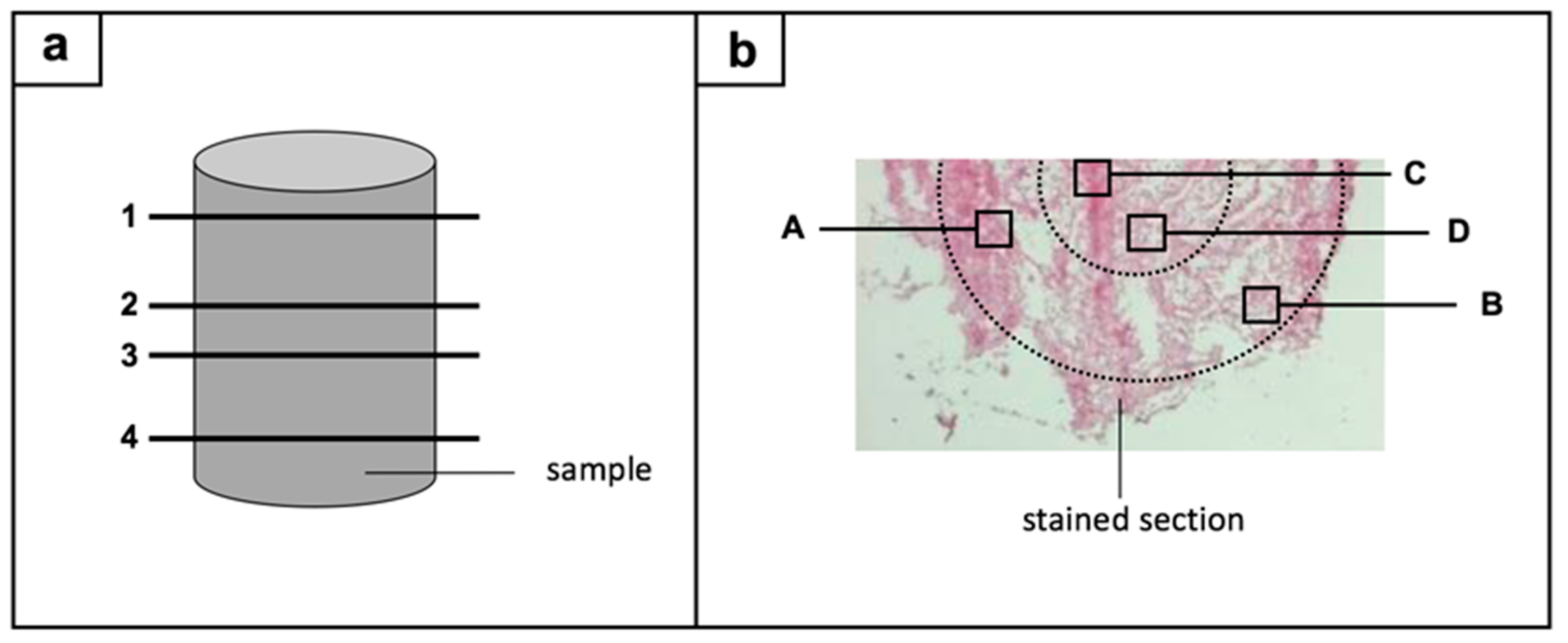
Figure 1. Regions-of-interest are illustrated in a two-way-process: (a) four sections (1–4) were chosen from each sample: one from the upper area, two from the middle, and one section from the lower area; (b) next, four regions per section were histologically evaluated: two edge regions (A,B) and two central regions (C,D).
Jfmk 02 00042 g001
Figure 2. Image processing is demonstrated with (a) original image; (b) the binary image; (c) the skeleton image; and (d) the structure analysis with the output image. The plug-in Angiogenesis Analyzer processed the one-line-wide structure according to the pre-defined elements, and Nd.Nd were displayed in purple (1), Nd.Tm in green (2), and Tm.Tm (3) in blue. The candidate section was mechanically compressed with a compression rate of 40%. Scale bars represent 100 µm.
Jfmk 02 00042 g002
Figure 3. The original image was overlapped with (a) the skeleton structure as well as (b) the network structure image. Scale bars represent 100 µm.
Jfmk 02 00042 g003
Figure 4. The degree of network connectivity was analyzed with (a) the N/F-Ratio followed by a strut analysis via (b) Nd.Nd-to-TLS-Ratio; (c) Nd.Tm-to-TLS-Ratio; and (d) Tm.Tm-to-TLS-Ratio.
Jfmk 02 00042 g004
Figure 5. Images present false feature identification during the processing workflow. Incorrect determination occurred within images with larger stained zones (a), with unclear transitions (b), and for struts next to the image edge (c). Detailed views are presented for the three cases (d,e,f). Scale bars represent 100 µm.
Jfmk 02 00042 g005