
Load Losses and Short-Circuit Resistances of Distribution Transformers According to IEEE Standard C57.110


Abstract
:1. Introduction
2. Materials and Methods
2.1. Load Losses of Three-Phase Transformers Adapted from IEEE Standard C57.110-2018
- are the power losses by Joule effect that would be produced when direct currents circulate through the transformer windings [37].
- are the eddy current losses due to the skin phenomenon in the conductors of the coils.
- are the other stray losses that originate in the tank and other metallic parts of the transformer due to electromagnetic induction.
- are the nominal losses in direct current.
- is the rated RMS value of the secondary currents of the transformer.
- is the RMS value of the harmonic of order ( = harmonic frequency, = 50–60 Hz is the fundamental frequency) of each phase () of the secondary currents.
- is the order of the highest-frequency harmonic used in the calculation.
2.2. Short-Circuit Resistances Referred to Secondary of Three-Phase Transformers
2.2.1. Effective Short-Circuit Resistance for Each Phase of the Transformer
- the increase in the short-circuit resistance of the transformer feeding non-linear loads, and
- the different values of the short-circuit resistances in each phase of the transformer with non-linear loads, not foreseen by L. Sima et al. in Equation (2).
- -
- and are the effective short-circuit resistances referring to each phase of the secondary, which represents the load losses in each phase of the three-phase transformers () according to IEEE Standard C57.110-2018 [10], caused by the circulation of currents () through each phase of the secondary winding. These resistances usually have different values in each phase when currents are distorted.
- -
- is the short-circuit reactance referred to as the secondary, representing the transformer’s scattered magnetic fluxes. This reactance has the same value in the three phases, because it depends only on the harmonic frequencies, not the current RMS values.
- -
- is the resistance that represents the transformer’s core losses. This resistance has the same value in each phase because it is not practically affected by the voltage harmonic frequencies.
- -
- is the magnetic reactance, which represents the main magnetic flux of the transformers and drives its electromotive forces. This reactance usually has the same values in each phase because of the same reasons indicated for .
2.2.2. Effective Short-Circuit Resistance of the Transformer
3. Results
- (1)
- the values of loss factors and short-circuit resistances increase with the imbalances of the current harmonics, and
- (2)
- the effective short-circuit resistances () have values different in each phase () and are different from the effective short-circuit resistance of the transformer (); these differences increase with the imbalances in the harmonics, as noted in case 1.
4. Discussion
- (1)
- The load losses calculated with our short-circuit resistances, referred to as the secondary of the three-phase transformers, developed in Section 2.2, are equal to those resulting from applying the IEEE Standard C57.110-2018.
- (2)
- The short-circuit resistance of L. Sima, referred to as secondary (), coincides with our effective short-circuit resistance (), referred to as the primary of the transformer.
- (3)
- In general, the effective short-circuit resistance of the transformer () and therefore the resistance of L. Sima et al. cannot be used to calculate the load losses of each phase.
5. Conclusions
- The effective short-circuit resistances of the transformer () and therefore the short-circuit resistances of L. Sima et al. () are mathematical parameters unrelated to the energy phenomena of the transformer. The use of these resistances gives rise to errors in the calculation of the load losses in the transformer phases (), which increase with the harmonic imbalances. This fact has been verified in the operation of the transformer of an actual residential distribution network feeding two very differently unbalanced loads, both with the same . We have verified that if the loads are slightly unbalanced, the errors in the calculation of barely exceed 1% in some phases, while with moderately unbalanced loads, the errors exceed 16% (Table 9).
- Based on the above, the effective short-circuit resistances of the transformer () can only be used to calculate the total load losses of three-phase transformers according to IEEE Standard C57.110, but their use is not suitable for monitoring the operation of three-phase transformers.
- The effective short-circuit resistances of each phase () can be used to monitor the operating status of three-phase transformers. Both resistances are related to the energy phenomena that manifest in the transformer, since with them, the load losses of each phase () and total () of the transformer can be accurately calculated.
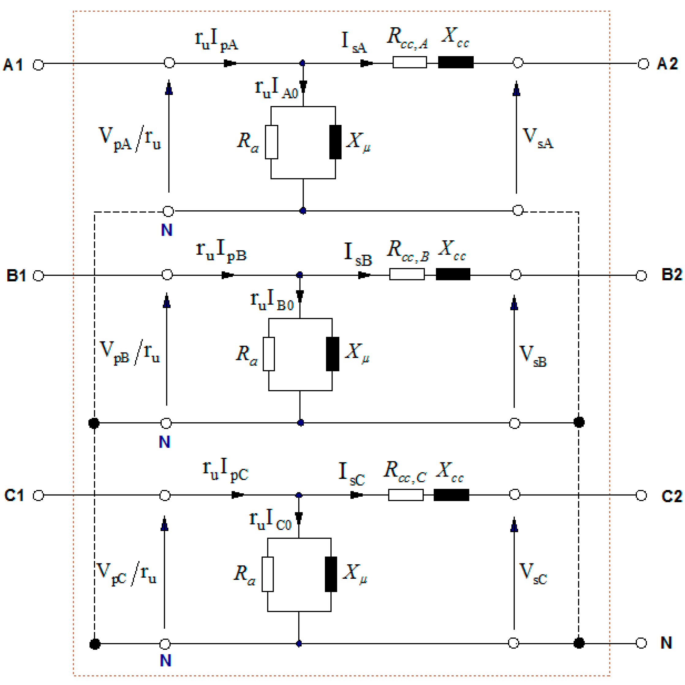
- The effective short-circuit resistances of each phase () define the accurate operating model of three-phase transformers, represented in Figure 2.
6. Patents
Author Contributions
Funding
Data Availability Statement
Conflicts of Interest
References
- Chorshanbiev, S.R.; Shvedov, G.V.; Sultan, H.M.; Nazirov, K.B.; Ismoilov, F.O. Structural Analysis of Power Losses in (6–10/0.4 kV) Urban Distribution Electric Networks of the City of Dushanbe, the Republic of Tajikistan. In Proceedings of the IEEE Conference of Russian Young Researchers in Electrical and Electronic Engineering (EIConRus), Saint Petersburg and Moscow, Russia, 28–31 January 2019. [Google Scholar] [CrossRef]
- U4E. Accelerating the Global Adoption of Energy-Efficient Transformers; UN Environment, Economy Division, Energy & Climate Branch: Paris, France, 2017. [Google Scholar]
- León-Martínez, V.; Andrada-Monrós, C.; Molina-Cañamero, L.; Cano-Martínez, J.; Peñalvo-López, E. Decarbonization of Distribution Transformers Based on Current Reduction: Economic and Environmental Impacts. Energies 2021, 21, 7207. [Google Scholar] [CrossRef]
- León-Martínez, V.; Peñalvo-López, E.; Andrada-Monrós, C.; Cano-Martínez, J.; León-Vinet, A.; Molina-Cañamero, L. Procedure for Improving the Energy, Environmental and Economic Sustainability of Transformation Houses. Appl. Sci. 2022, 9, 4204. [Google Scholar] [CrossRef]
- León-Martínez, V.; Peñalvo-López, E.; Montañana-Romeu, J.; Andrada-Monrós, C.; Molina-Cañamero, L. Assessment of Load Losses Caused by Harmonic Currents in Distribution Transformers Using the Transformer Loss Calculator Software. Environments 2023, 10, 177. [Google Scholar] [CrossRef]
- Mikhak-Beyranvand, M.; Faiz, J.; Rezaeealam, B. Thermal analysis and derating of a power transformer with harmonic loads. IET Gener. Transm. Distrib. 2020, 14, 1233–1241. [Google Scholar] [CrossRef]
- Gouda, O.E.; Amer, G.M.; Salem, W.A.A. Predicting transformer temperature rise and loss of life in the presence of harmonic load currents. Ain Shams Eng. J. 2012, 3, 113–121. [Google Scholar] [CrossRef]
- Borodin, M.; Psarev, A.; Kudinova, T.; Mukhametzhanov, R. Improving power quality by calculating voltage losses. Energy Systems and Complexes. In Proceedings of the International Scientific and Technical Conference Smart Energy Systems 2019 (SES-2019), Kazan, Russia, 18–20 September 2019. [Google Scholar] [CrossRef]
- Biryulin, V.I.; Gorlov, A.N.; Larin, O.M.; Kudelina, D.V. Calculation of power losses in the transformer substation. In Proceedings of the 2016 13th International Scientific-Technical Conference on Actual Problems of Electronics Instrument Engineering (APEIE), Novosibirsk, Russia, 3–6 October 2016. [Google Scholar] [CrossRef]
- C57.110-2018; IEEE Recommended Practice for Establishing Liquid Immersed and Dry-Type Power and Distribution. Transformer Capability When Supplying Nonsinusoidal Load Currents. Transformers Committee of the IEEE Power and Energy Society: New York, NY, USA, 2018. [CrossRef]
- Taher, M.A.; Kamel, S.; Ali, Z.M. K-Factor and transformer losses calculations under harmonics. In Proceedings of the 2016 Eighteenth International Middle East Power Systems Conference (MEPCON), Cairo, Egypt, 27–29 December 2016. [Google Scholar] [CrossRef]
- Contreras-Ramírez, D.; Lata-García, J. K-Factor Analysis to Increase the Actual Capacity of Electrical Distribution Transformers. In Communication, Smart Technologies and Innovation for Society; Springer: Berlin/Heidelberg, Germany, 2021; pp. 367–379. [Google Scholar] [CrossRef]
- Megahed, T.F.; Kotb, M.F. Improved design of LED lamp circuit to enhance distribution transformer capability based on a comparative study of various standards. Elsevier Energy Rep. 2022, 8, 445–465. [Google Scholar] [CrossRef]
- BSI-BS 7821-4; Three Phase Oil-Three Phase Oil-Immersed Distribution Transformers. 50 Hz from 50 to 2500 kVA with Highest Voltage for Equipment Not Exceeding 36 kV Part 4: Determination of the Power Rating of a Transformer Loaded with Non-Sinusoidal Currents. BSI: London, UK, 1995. Available online: https://standards.globalspec.com/std/33779/BS%207821-4 (accessed on 30 October 2023).
- AS 2374.1.-2003; Power Transformers Part 1: General. Standards Australia: Sydney, Australia, 2003. Available online: https://www.saiglobal.com/PDFTemp/Previews/OSH/as/as2000/2300/2374.1.2-2003(+A1).pdf (accessed on 30 October 2023).
- AS 2374.2; Dry-Type Power Transformers. Standards Australia: Sydney, Australia, 2003. Available online: https://infostore.saiglobal.com/en-gb/standards (accessed on 30 October 2023).
- IEC Standard 60076–18, Ed. 1.0; Measurement of Frequency Response. IEC: Geneva, Switzerland, 2012. Available online: http://atecco.ir/fa/wp-content/uploads/2021/07/IEC60076-part18-edition2012-FRA-measurements.pdf (accessed on 30 October 2023).
- IEEE Std C57.149–2012; IEEE Guide for the Application and Interpretation of Frequency Response Analysis for Oil-Immersed Transformers. IEEE: New York, NY, USA, 2013; pp. 1–72. Available online: https://pdfcoffee.com/ieee-std-c57-149-ieee-guide-for-the-application-and-interpretation-of-frequency-response-analysis-for-oil-immersed-transformerspdf-pdf-free.html (accessed on 30 October 2023).
- ANSI/UL Std. 1561 Ed. 4; Standard for Dry-Type General Purpose and Power Transformers. UL Standard: Northbrook, IL, USA, 2011; ANSI Approved 13 May 2019. Available online: https://webstore.ansi.org/standards/ul/ul1561ed2011 (accessed on 30 October 2023).
- ANSI/UL Std. 1562 Ed. 4; Transformers, Distribution, Dry-Type, Over 600 V. UL Standard: Northbrook, IL, USA, 25 January 2013; Revised 11 August 2020. Available online: https://webstore.ansi.org/standards/ul/ul1562ed2013 (accessed on 30 October 2023).
- Chen, H.; Huang, Y.; Hu, H.; Wang, J.; Wang, W. Analysis of the influence of voltage harmonics on the maximum load capacity of the power supply transformer for the LHCD system. In Proceedings of the IEEE 6th International Electrical and Energy Conference (CIEEC), Hefei, China, 12–14 May 2023. [Google Scholar] [CrossRef]
- Hao, M.; Xin, Z.; Chi, Z.; Xiaoguang, M.; Jufang, W.; Minghui, D. A 110kV transformer breakdown resulting from insufficient short circuit resistance. In Proceedings of the 2021 China International Conference on Electricity Distribution (CICED), Shanghai, China, 7–9 April 2021. [Google Scholar] [CrossRef]
- Chen, Q.; Wang, S.; Lin, D.; Wang, S.; Wang, S.; Yuan, D.; Li, H. Analysis of mechanical characteristics of transformer windings under short circuit fault. In Proceedings of the 2018 12th International Conference on the Properties and Applications of Dielectric Materials (ICPADM), Xi’an, China, 20–24 May 2018. [Google Scholar] [CrossRef]
- Gao, S.; Sun, L.; Tian, Y.; Liu, H. Research on the Distribution Characteristics of Transformer Axial Vibration under Short-Circuit Conditions Considering Damping Parameters. Appl. Sci. 2022, 12, 8443. [Google Scholar] [CrossRef]
- Ding, H.; Zhao, W.; Diao, C.; Li, M. Electromagnetic Vibration Characteristics of Inter-Turn Short Circuits in High Frequency Transformer. Electronics 2023, 12, 1884. [Google Scholar] [CrossRef]
- Xian, R.; Wang, L.; Zhang, B.; Li, J.; Xian, R.; Li, J. Identification Method of Interturn Short Circuit Fault for Distribution Transformer Based on Power Loss Variation. IEEE Trans. Ind. Inform. 2023, 1–11. [Google Scholar] [CrossRef]
- Bu, L.; Han, S.; Feng, J. Short-Circuit Fault Analysis of the Sen Transformer Using Phase Coordinate Model. Energies 2021, 14, 5638. [Google Scholar] [CrossRef]
- Cheema, M.A.M.; Fletcher, J.E.; Dorrell, D.; Junaid, M. A Novel Approach to Investigate the Quantitative Impact of Harmonic Currents on Winding Losses and Short Circuit Forces in a Furnace Transformer. IEEE Trans. Magn. 2013, 49, 2025–2028. [Google Scholar] [CrossRef]
- Dawood, K.; Alboyaci, B.; Cinar, M.C. The impact of short-circuit electromagnetic forces in a 12-pulse converter transformer. In Proceedings of the 2017 10th International Conference on Electrical and Electronics Engineering (ELECO), Bursa, Turkey, 30 November–2 December 2017; Available online: https://ieeexplore.ieee.org/abstract/document/8266210 (accessed on 30 October 2023).
- Wei, J.; Zhang, C.; Yao, C.; Li, S.; Duan, M.; Li, L.; Ma, X.; Ma, H. The cause analysis and preventive measures of transformer short circuit fault. In Proceedings of the 9th International Forum on Electrical Engineering and Automation (IFEEA), Zhuhai, China, 4–6 November 2022. [Google Scholar] [CrossRef]
- Ye, Z.; Yu, W.; Gou, J.; Tan, K.; Zeng, W.; An, B.; Li, Y. A Calculation Method to Adjust the Short-Circuit Impedance of a Transformer. IEEE Access 2020, 8, 223848–223858. [Google Scholar] [CrossRef]
- Zhihua, P.; Hongfa, Z.; Mingjian, T. Three-dimensional Leakage Magnetic Field Simulation and Short-circuit Impedance Calculation of Large Yoke Transformer. In Proceedings of the International Conference on Intelligent Computing, Automation and Systems (ICICAS), Chongqing, China, 29–31 December 2021. [Google Scholar] [CrossRef]
- Song, H.; Gu, K.; Zheng, X. Simulation test of transformer short-circuit impedance based on equivalent model at different frequencies. J. Vibroengineering 2022, 24, 1174–1187. [Google Scholar] [CrossRef]
- Zhao, R.; Gu, J.; Wang, C.; Wang, Y. Online Identification of High-Frequency Transformer Short-Circuit Parameters Based on Instantaneous Phasor Method. IEEE J. Emerg. Sel. Top. Power Electron. 2022, 10, 3677–3684. [Google Scholar] [CrossRef]
- Han, M.; Zhao, R.; Zhang, Y.; Zhang, Y. On-line identification of power transformer short-circuit parameters based on instantaneous phasor. IET Electr. Power Appl. 2023, 17, 1101–1110. [Google Scholar] [CrossRef]
- Sima, L.; Miteva, N.; Dagan, K.J. A novel approach to power loss calculation for power transformers supplying nonlinear loads. Elsevier Electr. Power Syst. Res. 2023, 223, 109582. [Google Scholar] [CrossRef]
- Pires-Corrêa, H.; Teles-Vieira, F.H. An Approach to Steady-State Power Transformer Modeling Considering Direct Current Resistance Test Measurements. Sensors 2021, 21, 6284. [Google Scholar] [CrossRef] [PubMed]
- C57.12.90™-2006; IEEE Standards Interpretation for IEEE Std. C57.12.90™-2006 IEEE Standard Test Code for Liquid-Immersed Distribution, Power, and Regulating Transformers. The Institute of Electrical and Electronics Engineers: New York, NY, USA, 2009. Available online: https://standards.ieee.org/wp-content/uploads/import/documents/interpretations/C57.12.90-2006_interp.pdf (accessed on 30 October 2023).


| POWER (kVA) | (W) | (W) | (W) | Secondary Rated Current (A) | Transformation Ratio () |
|---|---|---|---|---|---|
| 630 | 5900 | 200 | 400 | 866 | 24,000/420 V |
| Frequency (Hz) | Harmonic Order (h) | Secondary Currents (A) | |||
|---|---|---|---|---|---|
| A-Phase | B-Phase | C-Phase | Combined () | ||
| 50 | 1 | 278.345 | 403.233 | 305.503 | 577.412 |
| 100 | 2 | 14.32 | 9.571 | 13.518 | 21.895 |
| 150 | 3 | 4.093 | 10.877 | 2.129 | 11.815 |
| 200 | 4 | 14.884 | 3.562 | 13.036 | 20.103 |
| 250 | 5 | 33.541 | 16.762 | 6.983 | 38.141 |
| 300 | 6 | 16.088 | 7.711 | 16.159 | 24.070 |
| 350 | 7 | 19.980 | 18.350 | 10.392 | 29.050 |
| 400 | 8 | 22.621 | 15.445 | 23.481 | 36.078 |
| 450 | 9 | 20.366 | 19.781 | 22.514 | 36.234 |
| 500 | 10 | 14.689 | 11.486 | 12.990 | 22.725 |
| 550 | 11 | 10.203 | 2.713 | 5.895 | 12.091 |
| 600 | 12 | 10.452 | 4.591 | 9.289 | 14.717 |
| 650 | 13 | 4.393 | 7.096 | 13.158 | 15.581 |
| 700 | 14 | 11.194 | 2.962 | 12.144 | 16.780 |
| 750 | 15 | 14.002 | 4.085 | 15.535 | 21.309 |
| 800 | 16 | 14.919 | 5.887 | 12.204 | 20.153 |
| 850 | 17 | 33.999 | 22.709 | 38.182 | 55.942 |
| 900 | 18 | 21.875 | 11.785 | 20.646 | 32.305 |
| 950 | 19 | 10.553 | 7.124 | 10.106 | 16.255 |
| 1000 | 20 | 7.195 | 2.759 | 8.437 | 11.426 |
| 1050 | 21 | 7.697 | 3.225 | 8.727 | 12.075 |
| 1100 | 22 | 7.760 | 1.113 | 9.491 | 12.310 |
| 1150 | 23 | 9.949 | 4.723 | 9.599 | 14.609 |
| 1200 | 24 | 13.225 | 3.168 | 12.903 | 18.746 |
| 1250 | 25 | 11.977 | 9.367 | 9.618 | 17.991 |
| TOTAL | 289.75 | 406.50 | 314.23 | 589.86 | |
| Frequency (Hz) | Harmonic Order (h) | Secondary Currents (A) | |||
|---|---|---|---|---|---|
| A-Phase | B-Phase | C-Phase | Combined () | ||
| 50 | 1 | 195.165 | 195.462 | 226.837 | 357.4210 |
| 100 | 2 | 13.411 | 16.062 | 15.774 | 26.2042 |
| 150 | 3 | 17.034 | 12.235 | 29.030 | 35.8133 |
| 200 | 4 | 16.350 | 17.177 | 20.707 | 31.4825 |
| 250 | 5 | 29.179 | 21.472 | 14.281 | 38.9411 |
| 300 | 6 | 6.029 | 14.787 | 8.218 | 17.9593 |
| 350 | 7 | 12.464 | 14.051 | 20.427 | 27.7497 |
| 400 | 8 | 7.344 | 6.755 | 6.903 | 12.1332 |
| 450 | 9 | 7.639 | 7.147 | 10.946 | 15.1409 |
| 500 | 10 | 3.483 | 6.534 | 2.550 | 7.8311 |
| 550 | 11 | 13.709 | 5.117 | 4.123 | 15.2026 |
| 600 | 12 | 3.437 | 4.745 | 3.060 | 6.6099 |
| 650 | 13 | 3.948 | 4.927 | 6.909 | 9.3593 |
| 700 | 14 | 1.423 | 2.793 | 0.139 | 3.1377 |
| 750 | 15 | 4.454 | 4.767 | 3.878 | 7.5895 |
| 800 | 16 | 1.929 | 1.979 | 2.086 | 3.4625 |
| 850 | 17 | 1.667 | 1.766 | 2.033 | 3.1671 |
| 900 | 18 | 1.998 | 1.404 | 1.454 | 2.8420 |
| 950 | 19 | 1.317 | 1.087 | 0.936 | 1.9473 |
| 1000 | 20 | 1.118 | 0.910 | 0.902 | 1.7004 |
| 1050 | 21 | 0.937 | 0.721 | 0.619 | 1.3345 |
| 1100 | 22 | 0.882 | 0.949 | 0.541 | 1.4040 |
| 1150 | 23 | 1.002 | 0.819 | 0.883 | 1.5666 |
| 1200 | 24 | 1.134 | 0.924 | 0.991 | 1.7668 |
| 1250 | 25 | 0.772 | 0.902 | 0.633 | 1.3454 |
| TOTAL | 200.622 | 200.107 | 232.255 | 366.38 | |
| A-Phase | B-Phase | C-Phase | Transformer | |||||
|---|---|---|---|---|---|---|---|---|
| Case 1 (Table 2) | 14.6768 | 1.4645 | 3.4485 | 1.09 | 12.9388 | 1.3815 | 8.8511 | 1.2631 |
| Case 2 (Table 3) | 3.07619 | 1.15411 | 2.70159 | 1.12849 | 2.37866 | 1.11319 | 2.68413 | 1.13002 |
() | () | () | () | |
|---|---|---|---|---|
| Case 1 (Table 2) | 4.1874 | 3.1227 | 4.1802 | 3.6337 |
| Case 2 (Table 3) | 3.1010 | 3.0672 | 3.0317 | 3.0619 |
| Case 1 (Table 2) | 289.75 | 406.50 | 314.23 | 589.86 | 10.322 |
| Case 2 (Table 3) | 200.622 | 200.107 | 232.255 | 366.38 | 6.411 |
| Total Losses Using IEEE Std.C57.110 | Total Losses Using | Losses Using | ||||
|---|---|---|---|---|---|---|
| A-Phase | B-Phase | C-Phase | Total | |||
| Case 1 (Table 2) | 1264.321 | 1264.321 | 351.558 | 516.005 | 396.758 | 1264.321 |
| Case 2 (Table 3) | 411.011 | 411.011 | 124.814 | 122.658 | 163.539 | 411.011 |
| Referred to Primary () | Referred to Secondary () | |
|---|---|---|
| Case 1 (Table 2) | 11.865 | 3.6337 |
| Case 2 (Table 3) | 9.998 | 3.0619 |
| Load Losses (W) | Relative Loss Errors (%) | ||||||
|---|---|---|---|---|---|---|---|
| A-Phase | B-Phase | C-Phase | Total | A-Phase | B-Phase | C-Phase | |
| Case 1 (Table 2) | 305.073 | 600.448 | 358.800 | 1264.321 | 13.222 | −16.365 | 9.567 |
| Case 2 (Table 3) | 123.239 | 122.607 | 165.165 | 411.011 | 1.262 | 0.042 | −0.994 |
Disclaimer/Publisher’s Note: The statements, opinions and data contained in all publications are solely those of the individual author(s) and contributor(s) and not of MDPI and/or the editor(s). MDPI and/or the editor(s) disclaim responsibility for any injury to people or property resulting from any ideas, methods, instructions or products referred to in the content. |
© 2023 by the authors. Licensee MDPI, Basel, Switzerland. This article is an open access article distributed under the terms and conditions of the Creative Commons Attribution (CC BY) license (https://creativecommons.org/licenses/by/4.0/).
Share and Cite
León-Martínez, V.; Peñalvo-López, E.; Andrada-Monrós, C.; Sáiz-Jiménez, J.Á. Load Losses and Short-Circuit Resistances of Distribution Transformers According to IEEE Standard C57.110. Inventions 2023, 8, 154. https://doi.org/10.3390/inventions8060154
León-Martínez V, Peñalvo-López E, Andrada-Monrós C, Sáiz-Jiménez JÁ. Load Losses and Short-Circuit Resistances of Distribution Transformers According to IEEE Standard C57.110. Inventions. 2023; 8(6):154. https://doi.org/10.3390/inventions8060154
Chicago/Turabian StyleLeón-Martínez, Vicente, Elisa Peñalvo-López, Clara Andrada-Monrós, and Juan Ángel Sáiz-Jiménez. 2023. "Load Losses and Short-Circuit Resistances of Distribution Transformers According to IEEE Standard C57.110" Inventions 8, no. 6: 154. https://doi.org/10.3390/inventions8060154
APA StyleLeón-Martínez, V., Peñalvo-López, E., Andrada-Monrós, C., & Sáiz-Jiménez, J. Á. (2023). Load Losses and Short-Circuit Resistances of Distribution Transformers According to IEEE Standard C57.110. Inventions, 8(6), 154. https://doi.org/10.3390/inventions8060154