Article

Expansion Work Recovery of Hydrogen for a FC-Truck-Tentative Design of an Expansion Machine

EPFL—Ecole Polytechnique Fédérale de Lausanne, CH1015 Lausanne, Switzerland
Inventions 2023, 8(4), 89; https://doi.org/10.3390/inventions8040089
Submission received: 16 June 2023 / Revised: 2 July 2023 / Accepted: 3 July 2023 / Published: 5 July 2023

Abstract

:
Hydrogen powered vehicles use high-pressure reservoirs from which the gas is transferred to the low-pressure fuel-cell via a classical pressure reduction valve. In these systems no expansion work is recovered and the question is addressed of the potential to increase global efficiency by using an expansion machine between the reservoir and the electrochemical reactor. This paper investigates the feasibility of such an expansion machine, and evaluates the mechanical constraints in terms of forces, torques and produced power by numeric simulation. It further evaluates the energetic contribution to the whole conversion chain from the hydrogen reservoir to the common electrical network on board. A low-energy contribution of the expansion system addresses the question of the real benefit of such an investment.

1. Introduction

In the context of the decarbonation actions and renouncement of fossil fuels, hydrogen is expected to play an important role in the future of transportation [1]. For all of the advantages of an electric propulsion system, the powering of vehicles with fuel-cells and hydrogen presents many advantages as a large range in comparison to battery EV’s. One of the greatest advantages is the very short refuelling time [2]. Hydrogen on board is realized in the form of a high-pressure tank, but the operation of the fuel-cell converter only requires the pressure of 1–3 bar. For the reduction of pressure from the reservoir level to the fuel-cell, current vehicles use simple pressure reduction valves with cross section changes. In these systems, no work is recovered from the expansion process.
The potential of recovery of the expansion work of hydrogen for fuel-cell vehicles has been analyzed in [3]. The proposal is made for a replacement of the passive pressure reduction valve by an expansion engine followed by an electric generator in which output power is injected into the electric circuit of the vehicle for further use in propulsion for an expected increase of the normal range. This valuable principle addresses the question of available expansion machinery and their energetic performance. Figure 1 gives a schematic representation of a fuel-cell heavy vehicle with its main components. H2 is flowing from the pressurized tank through the expansion machine before being converted into electric power in the fuel-cell. The expansion machine drives a dedicated generator from which the power is rectified by a power electronic converter and fed to the main electric circuit. In this diagram, a buffer battery is also shown as well as the propulsion machines. This paper is an attempt to design such an expansion machine and to evaluate its main parameters and constraints. Further, the average of the recovered power is calculated and compared to the power delivered by the fuel-cell. These calculations will be a base for the evaluation of the added value of the expansion equipment to the vehicle.
The main issue of this study and development will be the improvement of the energy efficiency of systems using pressure reduction valves.
Expansion work recovery machines are dedicated first to the next generation of fuel-cell vehicles and can be developed by the future automotive industry. In a more general context of future energy storage facilities based on compressed hydrogen, they will improve the total energy efficiency of such systems. Applications to different fluids is also possible; for example, for compressed air driven machines and vehicles where pressure reduction valves are used today. Compressed Natural Gas (CNG) is another candidate for expansion machines.

2. Materials and Methods

Compressors for hydrogen-filling stations have been developed in recent years according to two dominant technologies. The leading technology in countries like Germany is the ionic compressor based on a liquid piston principle. Other systems use piston engines where the traditional pneumatic actuator has recently been replaced by a hydraulic cylinder for energetic efficiency reasons. A very recent development includes an original automatic seal exchange of the hydrogen high-pressure seal in order to reduce the revision downtime to a minimum [4]. Reversible compressors, namely, expansion machines adapted to the specific pressure range, are however not common industrial components and must be specially developed for the recovery function studied in this contribution.

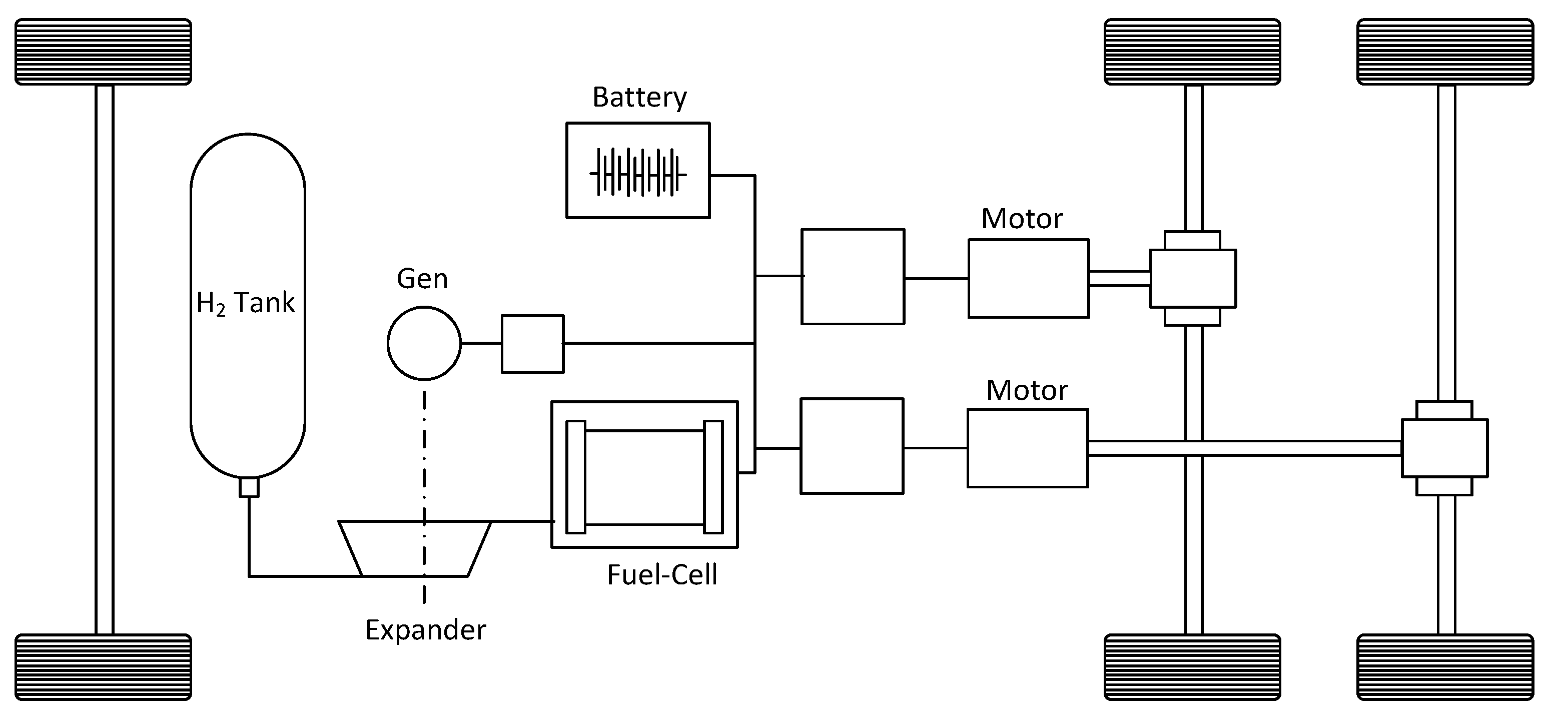
2.1. A Dedicated Expansion Machine

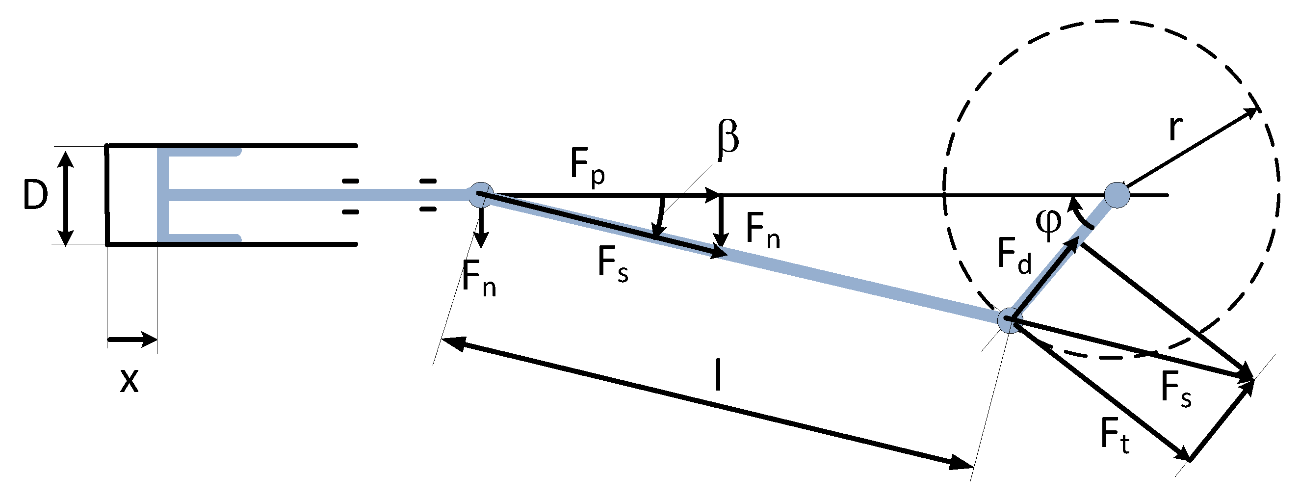
2.1.1. Single-Sided Pistons with Crankshaft and Piston Rod

In this study, the considered machine is defined as a piston/cylinder arrangement where the principle of an intake-and-expand sequence will be implemented according to the principles described in [5,6,7]. Figure 2 shows the basic diagram of the expansion machine actuated by rotational equipment comprising a crankshaft and piston rods. The crankshaft is coupled to an electric motor via a toothed belt gear ratio. On both sides of the crankshaft, there are three cascaded cylinders for the intake, expansion and exhaust process.
The expansion of the gas is realized within two stages where the transfer of the fluid from V1 to V2 corresponds to a first stage of expansion, while the transfer from V2 to V3 corresponds to the second expansion stage. The three cascaded cylinders are characterized through their volumes (V1, V2, V3), their surfaces (S1, S2, S3) and the corresponding diameters of the pistons D1, D2, D3. The pistons are operated in phase opposition with crank pins offset by 180 degrees. The cylinders of the machine are chosen as single-sided pistons for a unidirectional high-pressure solicitation of the sealings on one hand, and to avoid the piston-rod side seals on the other hand. Double acting cylinders would further have the disadvantage of dissymmetric left and right volumes with consequences on the modulation of the global output torque. The six-cylinder architecture results from the principle of having two expansion stages where the second expansion uses the receiving (expansion) cylinder of the first stage as a source for the second expansion during the return stroke. If the use of an interstage heat exchange element is necessary, another architecture can be envisaged in order to avoid undesired dead volumes. The two expansion stages should be identic and each have a filling and an expansion cylinder. This means two cylinders per stage leading to a total of four. If the principle of reciprocating is maintained (180° shifted crankpins), the total number of cylinders becomes equal to eight.

2.1.2. Basic Principle of the Expansion Machine

The basic principle of operation is described for the left-side arrangement of the three cylinders V1a, V2a and V3a. During the first half cycle, the small cylinder is filled with hydrogen at the constant high-pressure value. Then, after this filling, the gas is transferred to the larger cylinder V2 during the return stroke. During this transfer, the gas occupies an evolutive volume starting from V1 and reaching the value of V2 at the end of the return stroke. The ratio of V1/V2 corresponds to the expansion factor. Simultaneously to the filling and first expansion within V1 and V2, a second expansion occurs in the next period with a further transfer of the gas from V2 to V3 before the expanded gas is exhausted from V3 to the output during the following return stroke. The expansion factors are defined as V1/V2 for the first stage and V2/V3 for the second one. The pressures in the different volumes are represented in Figure 3 together with the control signals of the different valves.

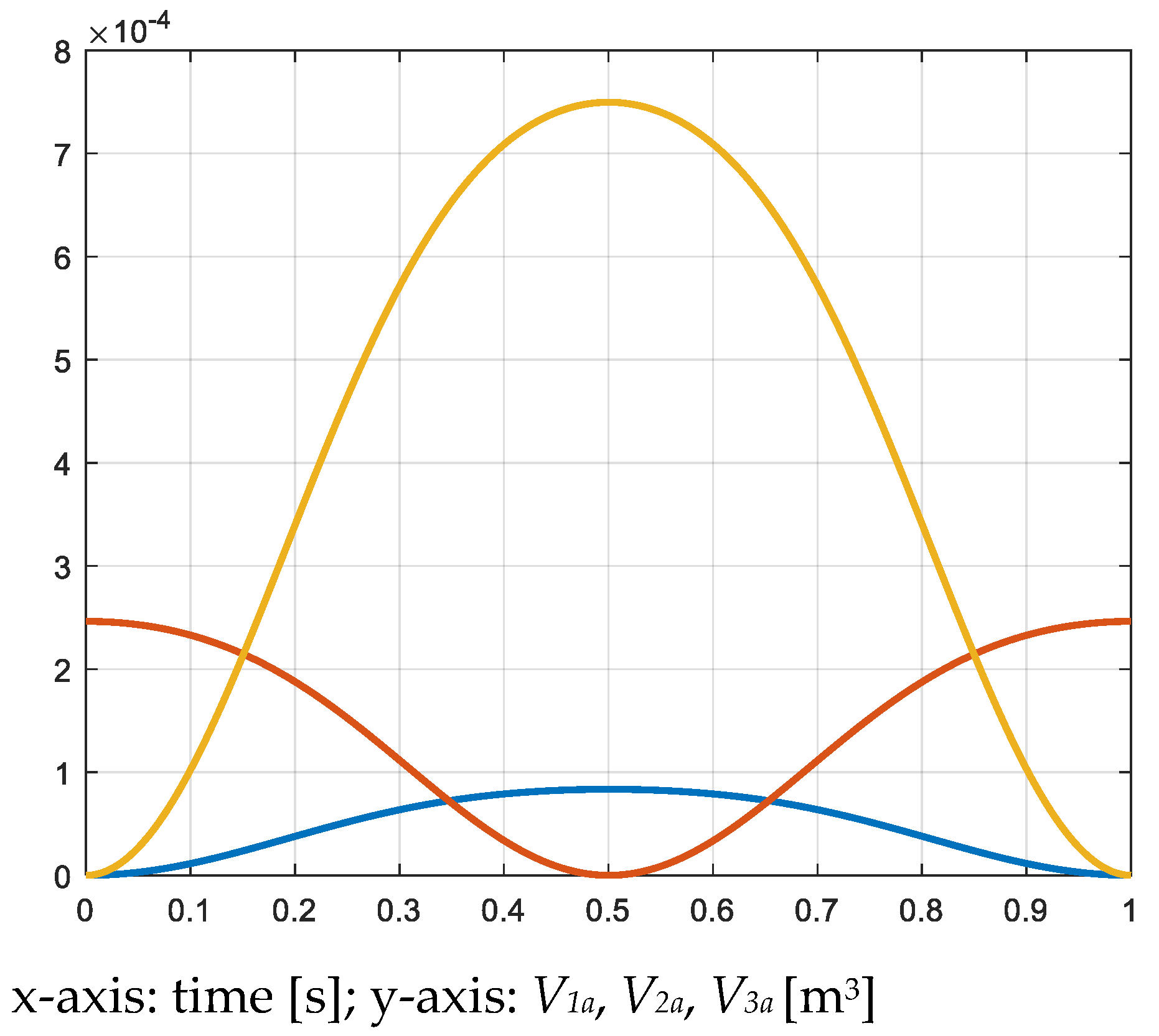
2.1.3. Estimation of the Needed Cylinder Volumes

The design of the expander is based on a maximum H2 consumption of 4.8 g per second, which is related to a heavy truck [7,8]. During each half cycle, the first cylinders must intake and transfer half of that mass of gas, namely 2.4 g, when the expansion cycle is defined as 1 s. The choice for the cycle time of the expansion process will be explained in Section 3.1.2; it will also have a consequence of the piston’s section and finally on the force exerted on it by the pressure. The mass of 2.4 g fills the first volumes after the intakes at a pressure of 350 bar or 350 × 105 N/m2. The calculation of the volume of the first cylinders is based on the number of moles n in the volume under a pressure of 350 bar.
n = m M = 2.4 g 2 g / mol = 1.2 mol ,
M being the molar mass of hydrogen.
V 1 = n R T P = 1.2 mol 8.31 J / mol × K 293 K 350 10 5 N / m 2 = 0.0000835 m 3
For the volume V2, three times of the value of V1 is considered. This comes from the choice of a total expansion factor equal to 9 for the cascade of the two stages. The expansion curve can be between an adiabatic or isothermal characteristic, and considering the worst case under the lowest pressure in the reservoir, namely 50 bar, the output pressure of the expander in this case becomes equal to
P 3 = P 1 V 1 V 2 V 2 V 3 γ = 50 10 5 1 9 1.4 = 2.3 10 5 N / m 2
V 2 = 3 V 1 = 0.00025 m 3
For the third volume which is defined by the volume ratio of the second expansion stage, the same ratio is considered
V 3 = 3 V 2 = 0.00075 m 3
Table 1 indicates the values of the pressures and temperatures after the two expansion stages in function of the input pressure, under adiabatic expansion. Table 2 indicates the same values but for the isothermal case. The calculated pressures correspond to
P 2 = P 1 V 1 V 2 γ
with γ = 1.4.
P 3 = P 2 V 2 V 3 γ
with γ = 1.4.
The values of the temperatures are given through
T 2 = T 1 V 2 / V 1 γ 1
T 3 = T 2 V 3 / V 2 γ 1
The calculated volumes of the three cylinders correspond to an input pressure of 350 bar. When the pressure in the reservoir decreases in dependency of the hydrogen consumption, a mass flow of 4.8 g/s can be maintained with the same volumes, but with an increase of the rotational speed of the machine.

2.1.4. Design of the Piston’s Sections and Diameters
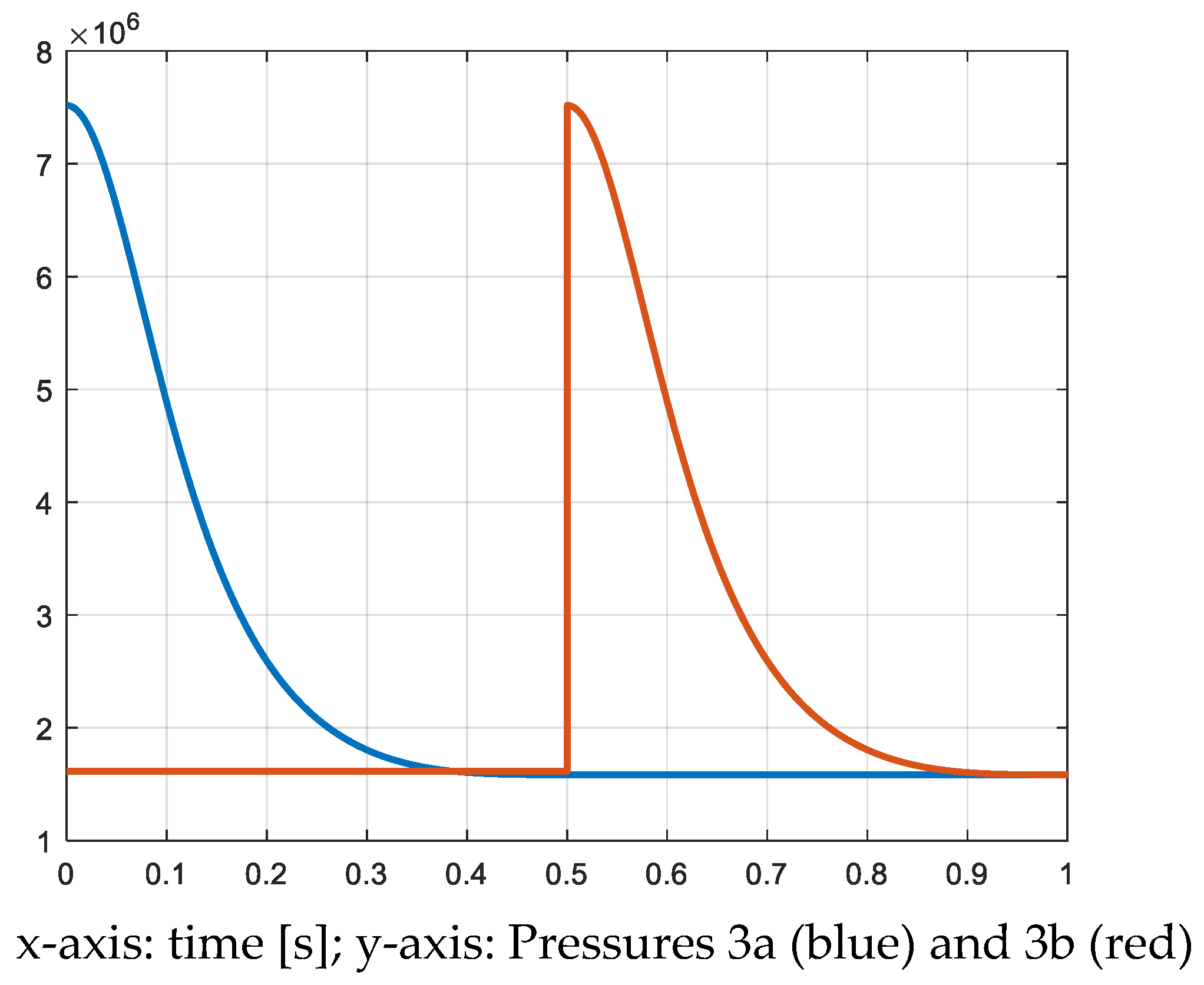
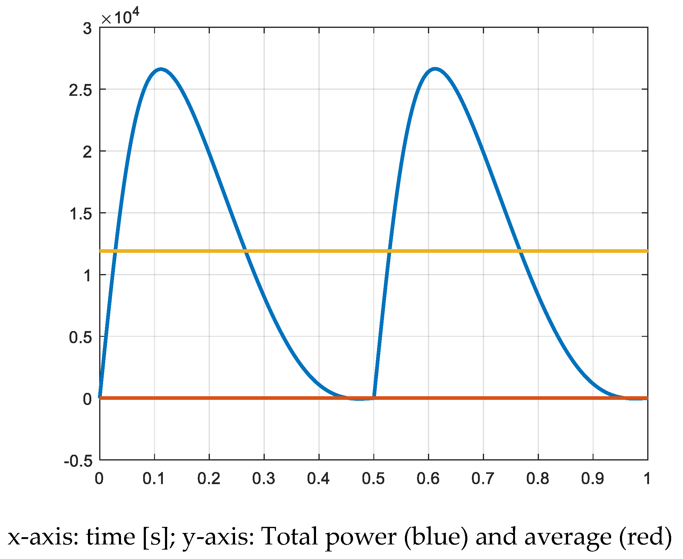
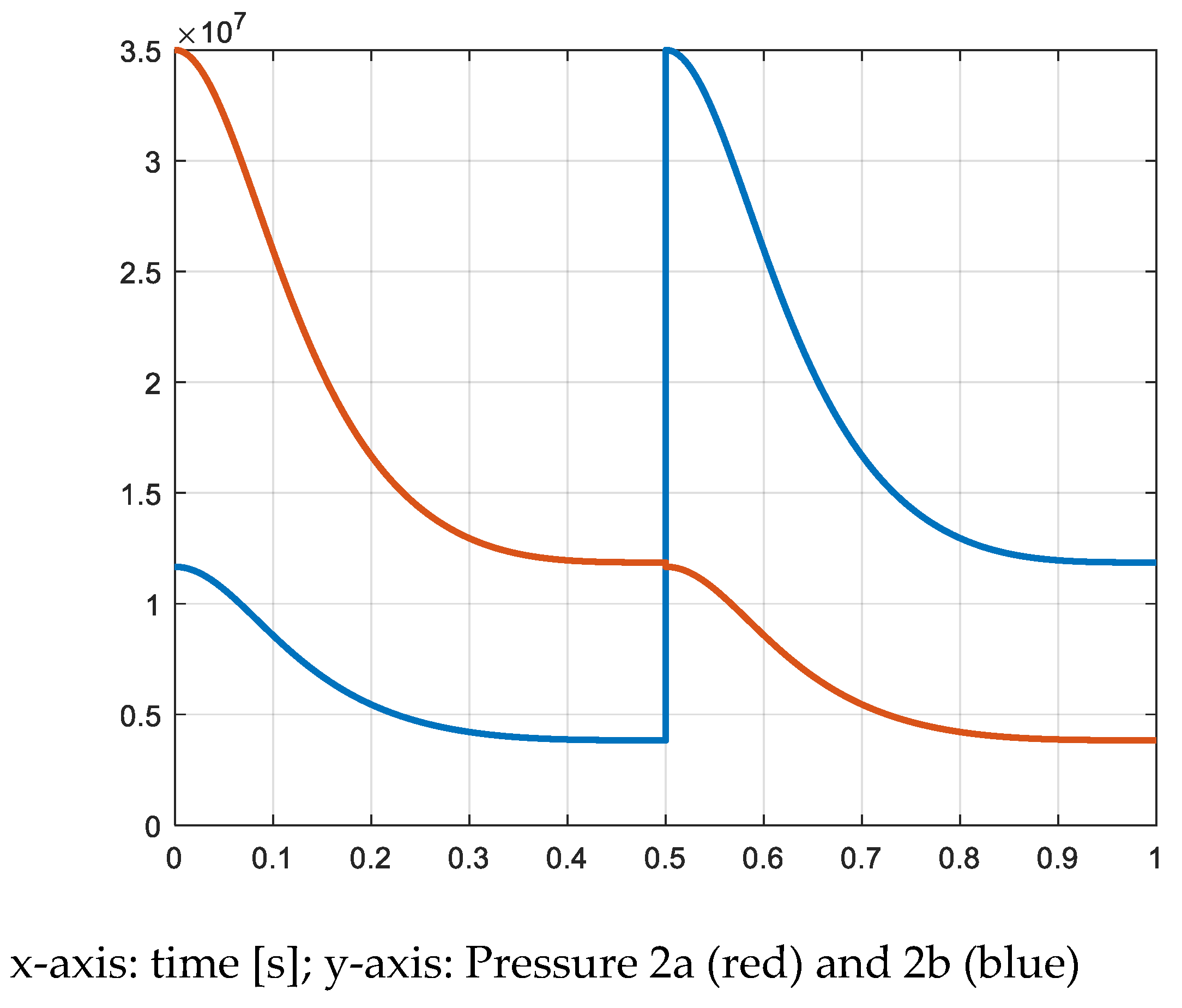
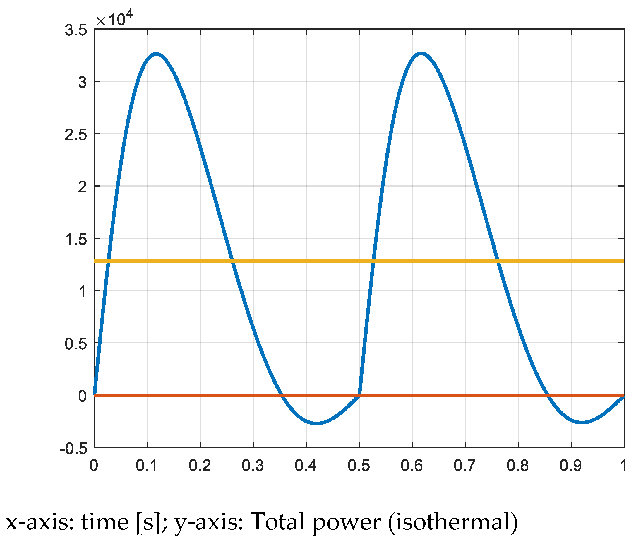
After having calculated the volumes of the cylinders, the sections and diameters of the pistons are calculated. For this calculation the radius of the crankshaft is first defined: r = 50 mm. Then, the stroke being 100 mm, the piston surfaces are calculated as
S 1 = V 1 l = 0.0000835 m 3 0.1 m = 0.000835 m 2 = 8.35 cm 2
S 2 = V 2 l = 0.00025 m 3 0.1 m = 0.0025 m 2 = 25 cm 2
S 3 = V 3 l = 0.00075 m 3 0.1 m = 0.0075 m 2 = 75 cm 2
For the dimensions of the cylinders, the diameters D1, D2 and D3 are calculated as
D 1 = 4 S 1 π = 4 8.35 cm 2 π = 3.26 cm
D 2 = 4 S 2 π = 4 25 cm 2 π = 5.6 cm
D 3 = 4 S 3 π = 4 75 cm 2 π = 9.77 cm
With the values of the different pressures and the different sections of the pistons, the value of the forces exerted are calculated with
F = P S
Table 3 shows the maximum values of the forces of the three pistons. It can already be seen that the realization of such an expansion machine is a real challenge when the forces are in the range of tens of kilo Newton.

3. Results

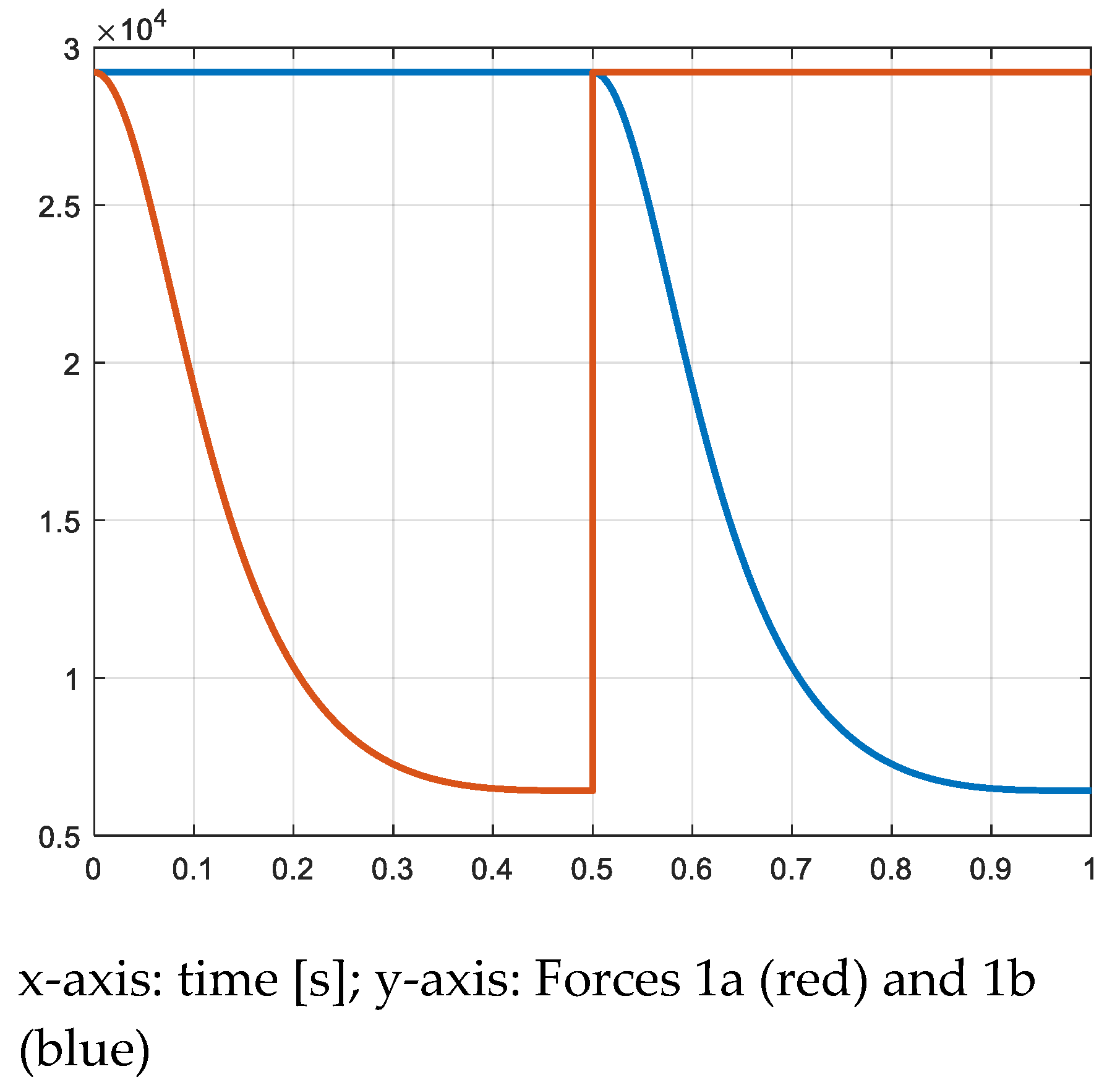
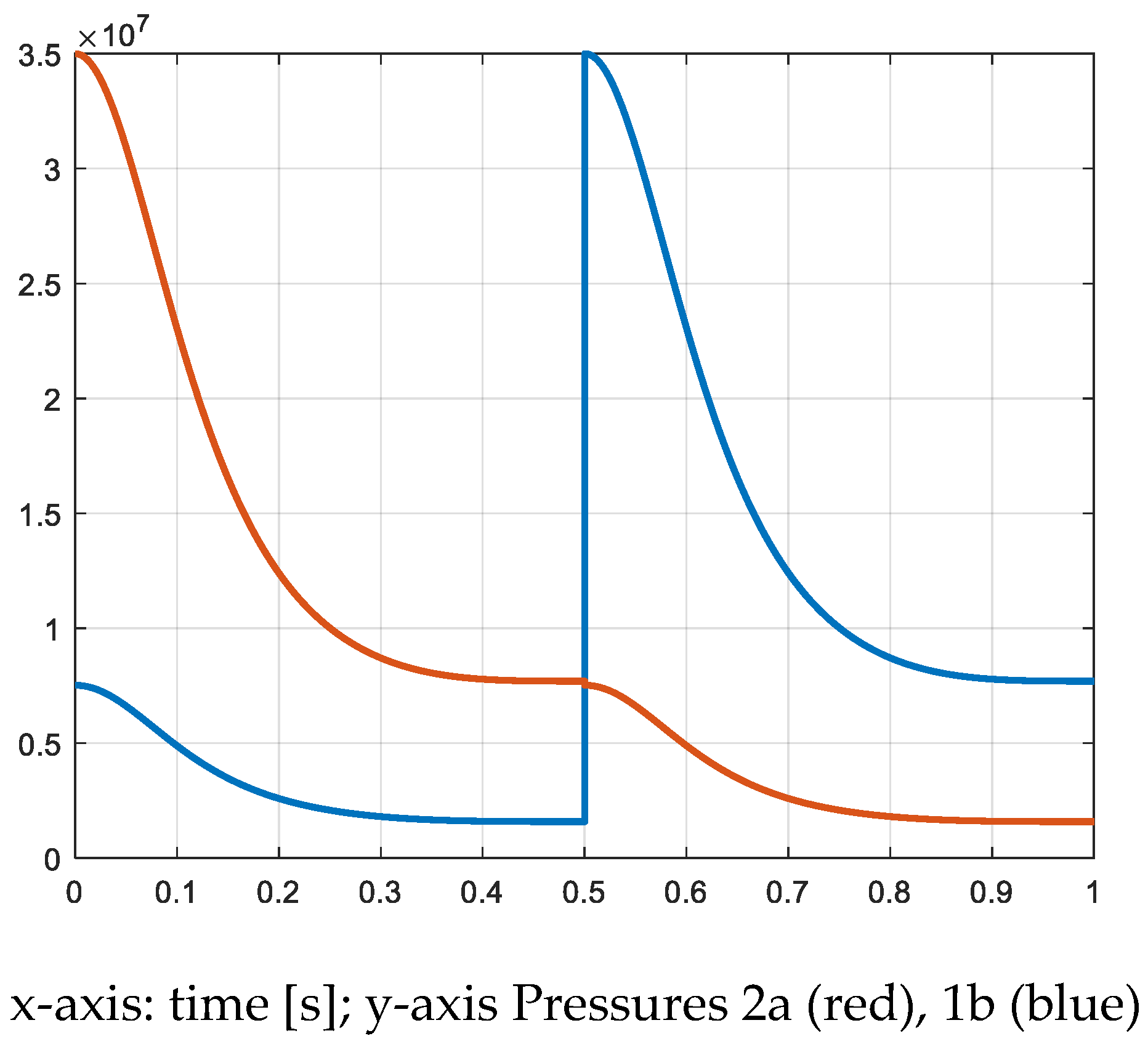
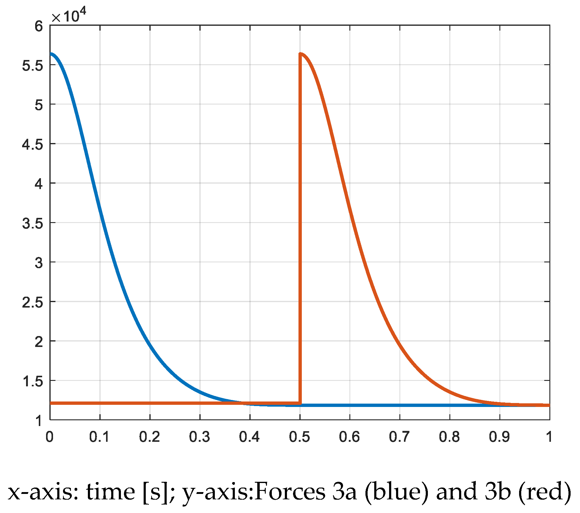
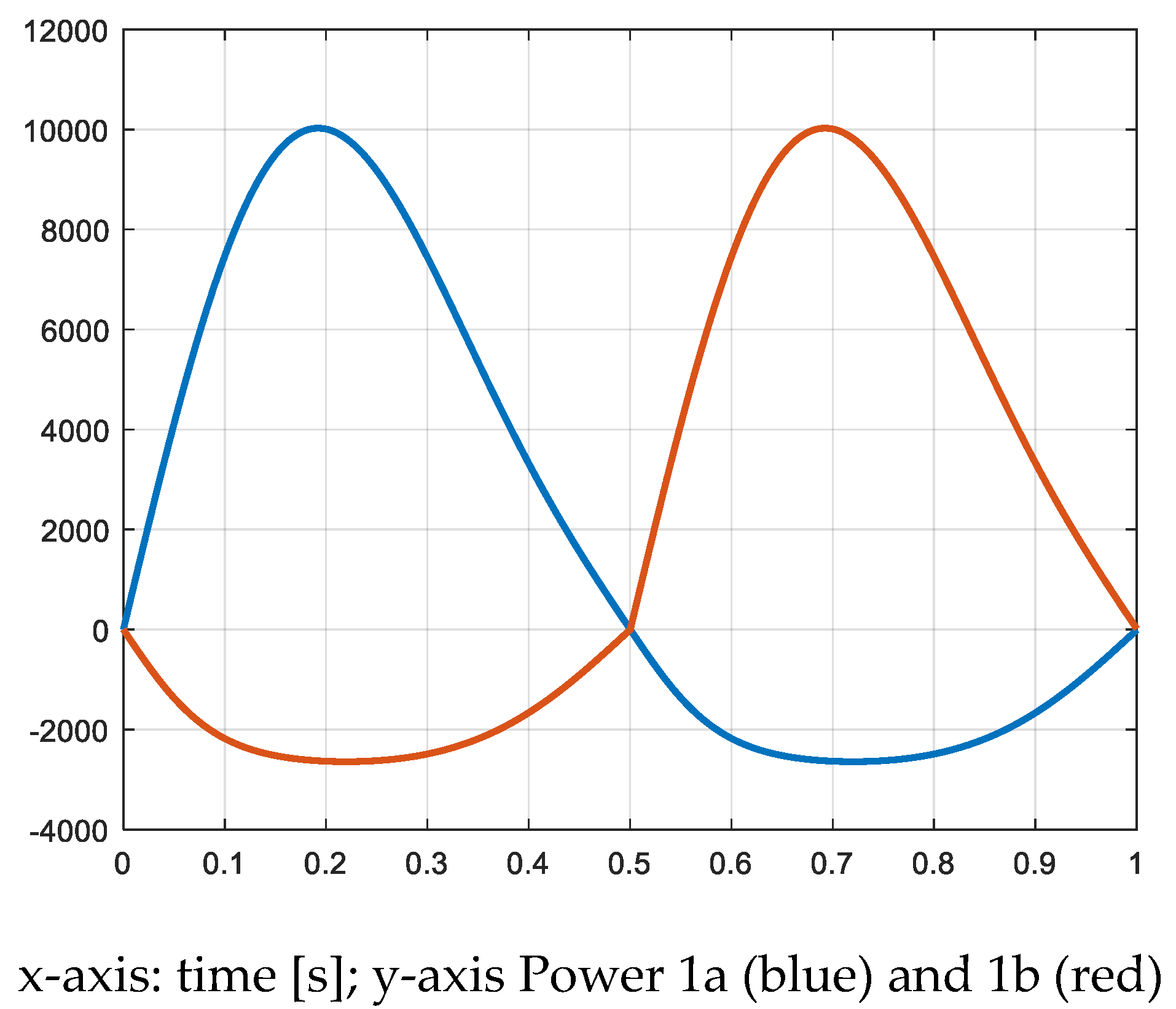
3.1. Modeling the Mechanical Constraints of the Special Machine

3.1.1. The Model of the Piston and Crankshaft

The next section gives the basic relations for a model of the piston and crankshaft assembly which will be used for the simulation of the mechanical and thermodynamic representation of the expansion machine [9]. In Figure 4, the different mechanical variables are defined.
The horizontal displacement of the piston is determined through Equation (17)
x = r ( 1 cos φ ) + λ 2 r sin 2 φ
In this relation, an additional parameter is used, namely the connecting rod ratio λ which is defined as
λ = r l
The piston’s velocity is calculated according to Equation (19)
v = ω r sin φ ( 1 + λ cos φ )
In this study, the torque developed by the motor is indirectly calculated through the power. The compression force exerted on the piston is given by the product of the pressure multiplied by the piston’s front area A.
F p = p A
The resulting mechanical power is defined by the product of the piston’s force by its velocity.
P o w = F p v
The torque is obtained by dividing the power by the angular velocity ω
M m o t = P o w / ω
With the other parameters and definition of the variables of Figure 4, the torque can be calculated without any consideration of the power and of the rotational speed [7]. As can be seen in the figure, the additional forces, such as the force which is parallel to the connecting rod Fs, the tangential force Ft and the reaction force Fn, are also defined. The torque on the crankshaft is given by Equation (23).
M m o t = F t r
The tangential force Ft is given by (24)
F t = F s cos ( π / 2 ( β + φ ) )
The force transmitted through the connecting rod Fs is calculated with the help of the piston force Fp and the angle beta (26).
F s = F p cos β
β = a r c sin r l sin φ
In Figure 4, the reaction force Fn which is perpendicular to the piston’s movement is given as per (27).
F n = F s sin β = F p cos β sin β
For this system using a crankshaft and a piston rod, a specific linear guiding element is needed which can hold the perpendicular reaction force at the bottom side of the piston. In this architecture, the piston rod cannot move inside the compression cylinder like in a normal piston assembly of a classical internal combustion engine. The consequence is that the total length of the compressor (in the direction of the piston’s displacement) is significantly increased.

3.1.2. Simulation of a Slow Expansion Machine

Related to the very low temperature levels reached after the two expansions, and in reference to the operation conditions of high-pressure gas boosters from the literature, a machine with slow rotational speed is chosen. The slow rotation and slow motion of the pistons will allow a better transfer of the heat from the cylinder walls to the expanded gas and produces a displacement of the p-v expansion curve from an adiabatic characteristic towards an isothermal one.
The rotational speed is supposed to be constant and equal to 6.28 rad/s. Figure 5 shows the evolution of the pistons Nr. 1a and Nr.2a (according to the definition of Figure 2) and Figure 6 shows the evolution of the volumes V1a, V2a and V3a. The position of the third piston (Nr 3a) is identic to the position of piston Nr. 1a.
In dependency of the variation of the volumes and taking into account the transfer of the gas from one cylinder to the other, the pressures in the different cylinders are calculated (Equations (6) and (7)). Then, the forces exerted on the pistons are calculated (Equation (20)). The waveforms of the pressures and of the respective forces are similar, but the values and units are totally different. In Figure 7, Figure 8, Figure 9, Figure 10, Figure 11 and Figure 12, the pressures and forces of the pistons a and b of cylinders 1, 2 and 3 are represented.
Further, multiplying the forces by the velocity of the pistons, the power produced is calculated (Equation (21)). By dividing by the rotational angular speed the torque produced is also calculated (Equation (22)). In Figure 13, Figure 14, Figure 15, Figure 16, Figure 17 and Figure 18, the power and torque of each piston and at each side (a and b) is represented. The maximum values of the torques produced by the pistons are given in Table 4.
Finally, the sum of the three powers giving the total power delivered by the expander is represented in Figure 19. The total torque produced is represented in Figure 20. The curves of Figure 19 and Figure 20 correspond to the performance of the expander for adiabatic expansion conditions.

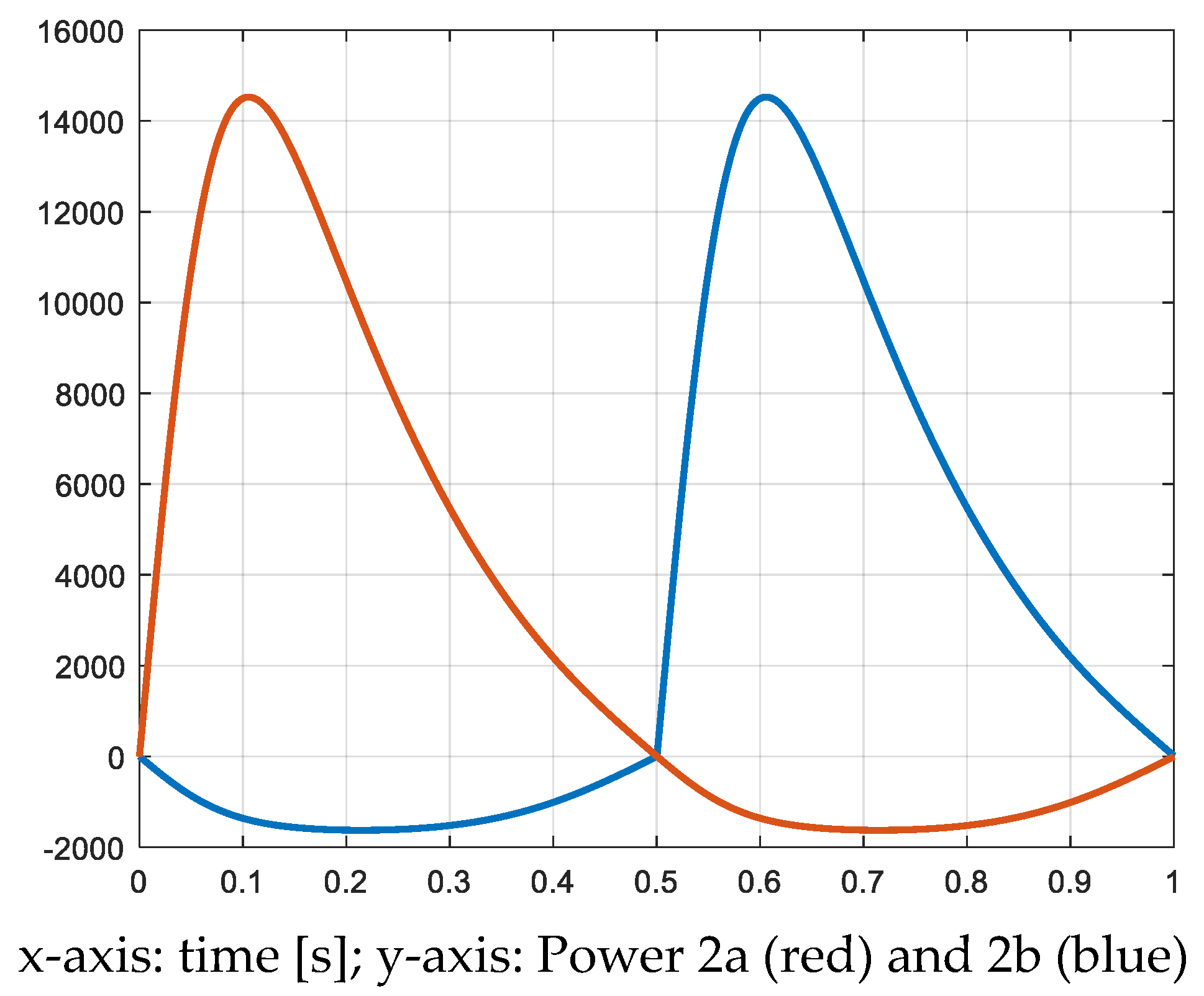
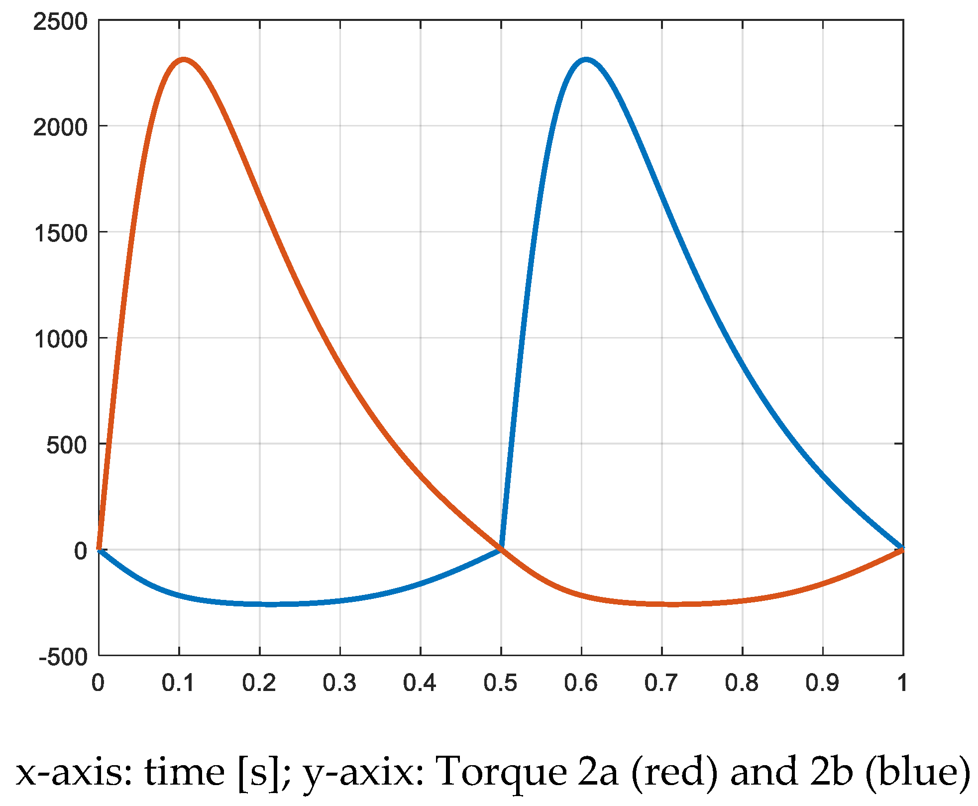
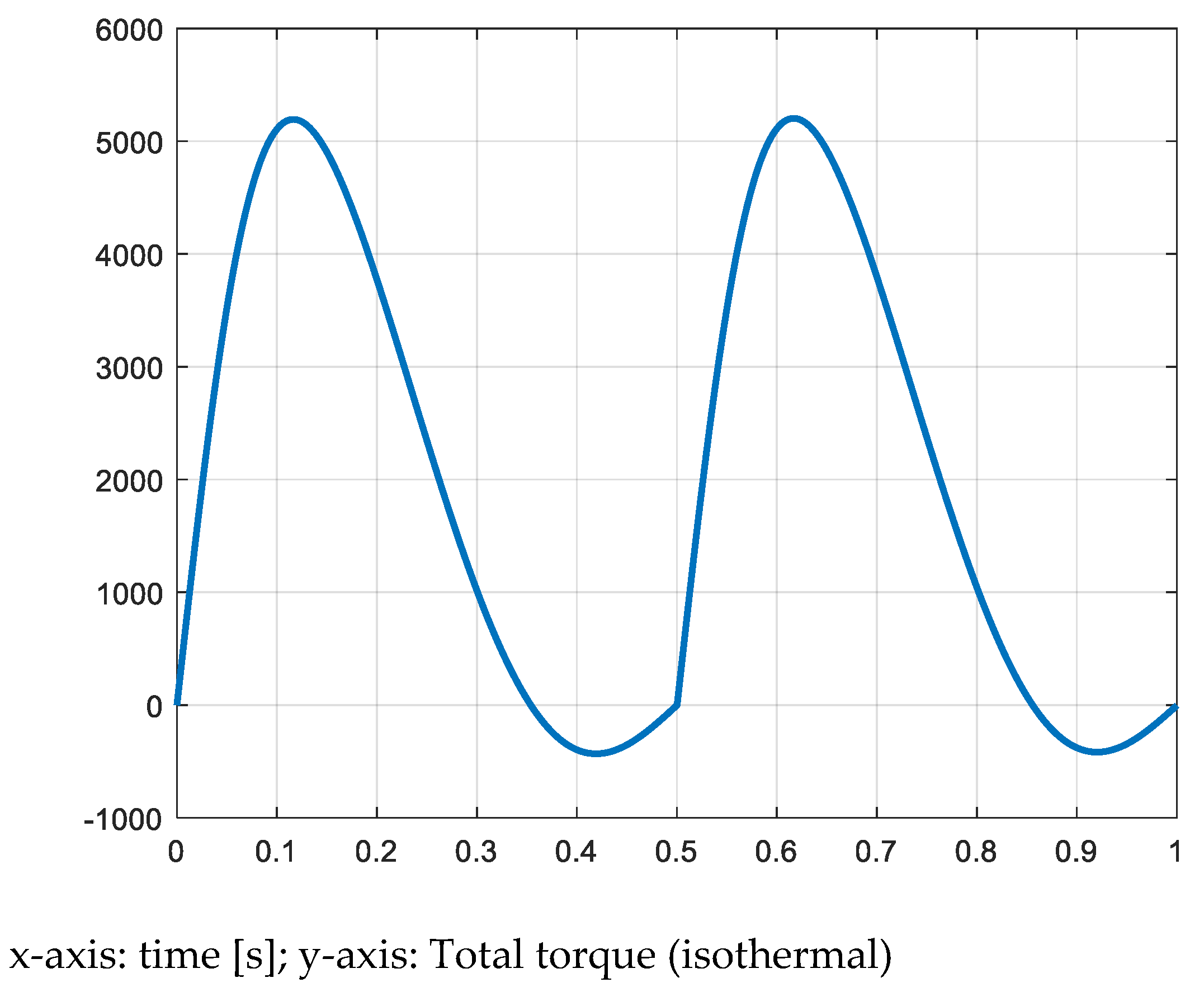
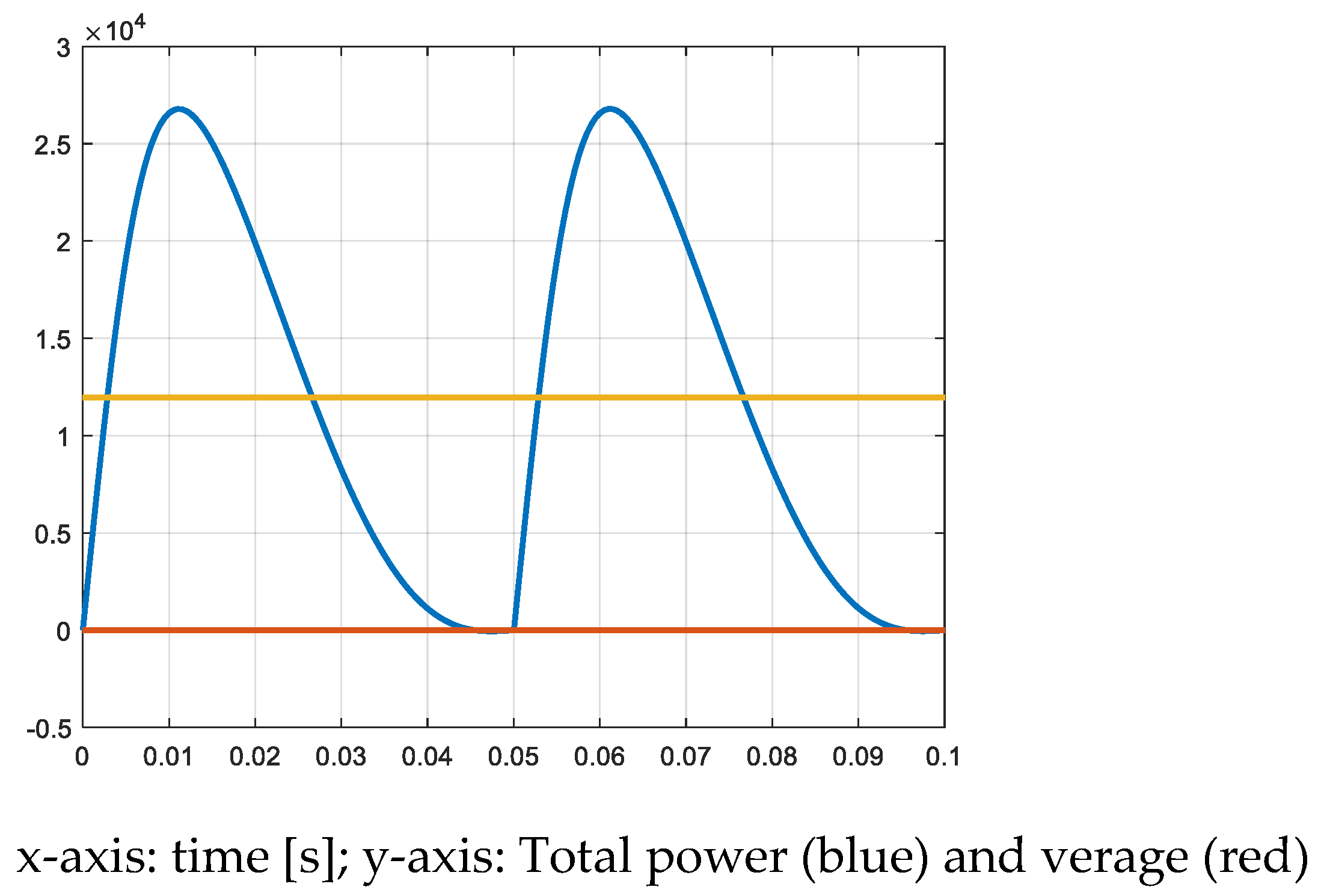
3.1.3. Isothermal Expansion

The expansions can be assumed to be realized according to an isothermal characteristic. Even if this cannot be achieved totally in a real system, the produced power and torque are slightly higher than in adiabatic conditions. The following simulations are realized for an evaluation of such a best case and show the most important system variables in isothermal conditions. To show the pressure variations during the expansions, the pressure in the second pistons is represented (Figure 21). Effectively, the pressure in the second cylinder also shows the variation of the pressure during the transfer from the first cylinder into the second during the first half-cycle, and the variation during the transfer from this second cylinder into the third one during the return stroke.
Figure 22 shows the instant value and the average of the produced total power in isothermal conditions. Figure 23 shows the corresponding torque.

3.2. A Faster Machine with Reduced Size and Constraints

The first design of the new expansion machine shows that, due to the high pressure of the gas, a low-speed machine leads to extreme mechanical constraints in terms of forces and torques. Consequently, a faster-running machine is designed and analyzed.

3.2.1. Dimensions of the Faster Machine

If the volume of the first cylinder is V1 = 0.0000835 m3 and corresponds to a hydrogen flow of 2.4 g/s when the period of the cycle is 1 s, the volume of the cylinder becomes
V 1 f = V 1 / 10 = 0.00000835 m 3
when the period is chosen as 0.1 s.
For the volume V2, three times of the value of V1 is considered
V 2 f = 3 V 1 f = 0.000025 m 3
For the third volume which defines the volumetric ratio of the second expansion stage, the same ratio is considered
V 3 f = 3 V 2 f = 0.000075 m 3
In order to keep the diameter of the small piston at a reasonable value, the stroke of the pistons is reduced to 0.05 m. Then the section of the small piston becomes
S 1 f = V 1 f l = 0.00008835 m 3 0.05 m = 0.000167 m 2 = 1.67 cm 2
S 2 f = V 2 f l = 0.000025 m 3 0.05 m = 0.0005 m 2 = 5 cm 2
S 3 f = V 3 f l = 0.000075 m 3 0.05 m = 0.0015 m 2 = 15 cm 2
For the dimensions of the cylinders, the diameters D1, D2 and D3 are calculated as
D 1 f = 4 S 1 f π = 4 1.67 cm 2 π = 1.46 cm
D 2 f = 4 S 2 f π = 4 5 cm 2 π = 2.52 cm
D 3 f = 4 S 3 f π = 4 15 cm 2 π = 4.37 cm
With the faster machine, the expansion factors are identical to the case of the previous machine. When the piston’s surfaces are different, the maximum of the forces is also different. Table 5 gives the maximum values of the produced forces in the case of the fast machine.

3.2.2. Simulation of the Faster Machine

In a similar way as was made for the slow machine, the different variables are simulated.
Figure 24 show the pressure in the cylinders 2a and 2b. The corresponding forces are shown in Figure 25. The waveforms are similar to the waveforms of the slow machine, but with values related to the new surfaces of the pistons. The values on the horizontal axis (time) are of course related to the new period of 0.1 s.
In Figure 26, the total power and its average value are represented. The torque is represented in Figure 27. These values are strongly reduced in comparison with the values obtained for the slow machine.

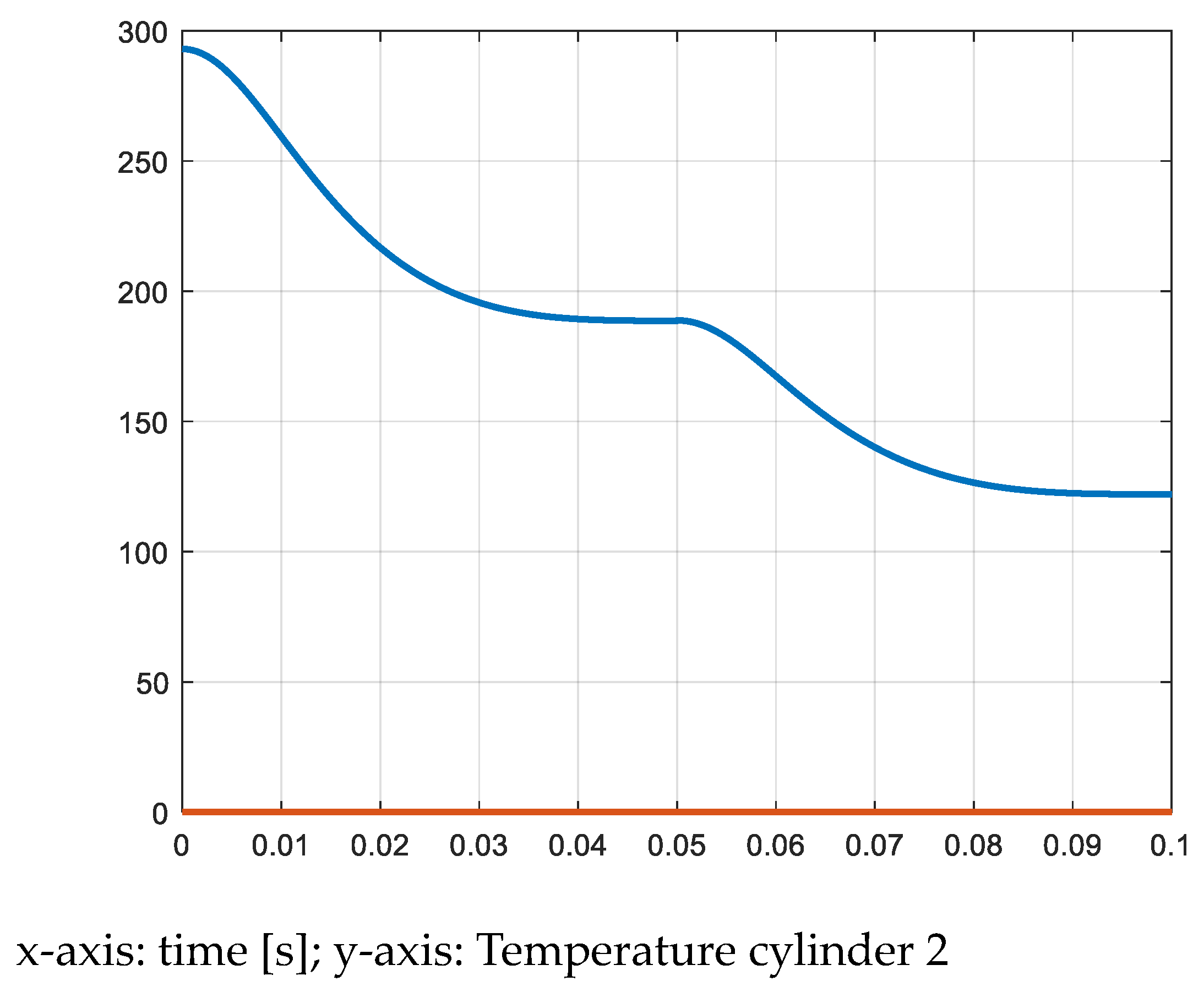
3.3. The Temperature in the Cylinders

The decrease of the temperature during the expansion is calculated through
T 2 = T 1 V 2 / V 1 γ 1
For the system described by the schematic diagram of Figure 2, there are two successive expansions leading to two successive decreases of temperature. The variation of temperature illustrating the two successive expansions can be observed in the second cylinder V2. During the first half period, the cylinder V2 is participating in a first expansion due to the transfer of hydrogen from cylinder V1 to cylinder V2. During the second half period, the same cylinder V2 is implicated in the second expansion where the gas is transferred from V2 to V3. The temperature curve of the double adiabatic expansion process is represented in Figure 28.
In Table 1, the final temperatures of the adiabatic expansions have been indicated (T2 and T3), the initial value of the hydrogen gas being 293 K before the expansions. The curve in Figure 28 shows that the temperature in cylinder 2 reaches asymptotically the same values of Table 1, namely T2 = 188 K and T3 = 121 K.

3.4. Energetic Considerations

The power capacity of an expansion system has been estimated in the sections dedicated to the machinery. From Figure 19 and Figure 26, the curves of the power produced by the two-stage reciprocating expanders show that the values are identic and that the output power is independent from the chosen nominal value of the rotational speed of the machine. By neglecting the friction of the piston seals and other parasitic losses, the amount of produced power is only depending on the flowrate of hydrogen to be expanded from the input pressure level to the output of the expander. Of course, the power will depend also on the quality of the expansion formulated through the polytropic factor. An isothermal expansion produces a higher power than an adiabatic one (Figure 22). The average value of the produced power in adiabatic conditions is 11.9 kW and can be converted into an electric power PGen by the generator driven by the expansion machine (Figure 1). The efficiency of the generator (Permanent Magnet Synchronous Generator) is evaluated as 93%. The value of the power produced and converted in the recovery chain will now be compared to the electric power PFC produced by the fuel-cell which converts the expanded amount of hydrogen. The power ratio of the recovered expansion power to the useful power PFC is then defined as
R r e cov = P G e n P F C
where PFC is calculated from the H2 flowrate of 4.8 g/s, with a heat value of H2 of 33 kW/kg and an efficiency of the fuel-cell of 60%
P F C = 4.8 g / s 33 Wh / g 3600 s / h 0.6 = 342 kW
The recovery factor Rrecov becomes
R r e cov = P G e n P F C = 11.9 kW 0.93 342 kW = 0.032 o r 3.2 %
The expansion power in isothermal conditions has been evaluated (see Figure 22); the recovery factor in this case becomes
R r e cov = P G e n P F C = 12.8 kW 0.93 342 kW = 0.0348 o r 3.48 %
This low value addresses the question of the motivation or the economic aspect of using expansion recovery systems in fuel-cell vehicles. An evaluation of the dimensions and weight of the components of the expansion system is necessary.

4. Discussion

The realization of an expansion machine for the recovery of the expansion work of hydrogen in a fuel-cell vehicle represent an enormous challenge for designers at the level of strong mechanical constraints such as forces and torques. A two-stage six-cylinder expander has been studied, where the rotational speed was kept at a low level due to the thermodynamic characteristic and to keep the expansion away from an adiabatic performance. In dependency of the variation of the pressure in the vehicle’s reservoir, the rotational speed can be increased when the gas mass flowrate demand corresponds to the nominal value of 4.8 g/s for a heavy truck. Starting from the nominal reservoir pressure of 350 bar, the mechanical constraints as the typical high torque of thousands of Nm addresses the question of its feasibility or of the size and weight of the equipment. A 10-times faster machine was also simulated, bringing a strong reduction of the constraints.
Adiabatic and isothermal expansions have been simulated, showing a limited performance increase between adiabatic and isothermal, even if the advantages of the nearly isothermal system would be useful for the thermal solicitation of cylinder and piston seals.
From the point of view of the amount of power produced by the gas expansion system in comparison to the power delivered from the chemical content of the gas through the fuel-cell, a limited benefit of only a few percent has been calculated.

5. Conclusions

A tentative design of a hydrogen expansion work recovery system has been realized where the pressures, forces, torques and power contributions of the two stages of a six-cylinder machine have been calculated by simulation. The huge mechanical constraints in a slow rotational speed machine could be strongly reduced by a second design of a faster running machine.
The limited power contribution of the expansion system addresses the technical and economic advantages of such a development. Implementing the studied expansion machine with the coupled generator and converter would increase the total weight of the vehicle, being a penalty for its performance in terms of additional fuel consumption, and corresponding range.

Funding

This research received no external funding.

Data Availability Statement

Not applicable.

Conflicts of Interest

The author declares no conflict of interest.

References

  1. Thanapalan, K.K.T.; Kim, J.R.; Carr, S.J.W.; Zhang, F.; Premier, G.C.; Maddy, J.; Guwy, A.J. Progress in the development of renewable hydrogen vehicles, storage, infrastructure in the UK: Hydrogen Centre in its early years of operation. In Proceedings of the 2011 2nd International Conference on Intelligent Control and Information Processing, Harbin, China, 25–28 July 2011; pp. 738–742. [Google Scholar] [CrossRef]
  2. Woo, H.; Son, Y.; Choi, S. EV charging demand and problem formulation for the optimization of the hydrogen-integrated electric vehicle charging station: A review. In Proceedings of the 2022 13th International Conference on Information and Communication Technology Convergence (ICTC), Jeju Island, Republic of Korea, 19–21 October 2022; pp. 335–337. [Google Scholar] [CrossRef]
  3. Muck, N.; Wieser, S. Analysis of hydrogen expansion’s potential for fuel cell electric vehicle’s efficiency. In Proceedings of the 2021 Sixteenth International Conference on Ecological Vehicles and Renewable Energies (EVER), Monte-Carlo, Monaco, 5–7 May 2021; pp. 1–9. [Google Scholar] [CrossRef]
  4. Maximator Hydrogen Technology Hydrogen Usage through High Efficient Max-Compression. Available online: https://www.maximator-ht.com/upload/2357089_Hydrogen-Solutions-Brochure_092020.pdf (accessed on 2 May 2023).
  5. Rufer, A. Pneumatic Cylinder Assembly with Reduced Air Consumption. WO 2022/232953 A1, 1 May 2021. [Google Scholar]
  6. Rufer, A. Pneumatic Actuator Systems with Enhanced Efficiency. Available online: https://www.coollibri.com/bibliotheque-en-ligne/alfred-rufer/pneumatic-actuator-systems-with-enhanced-efficiency_428767 (accessed on 1 May 2023).
  7. Rufer, A. A High Efficiency Pneumatic Motor Based on Double-Acting Linear Cylinders. World Wide J. Multidiscip. Res. Dev. WWJMRD 2021, 7, 5–9. Available online: https://wwjmrd.com/archive/2021/1/1476/a-high-efficiency-pneumatic-motor-based-on-double-acting-linear-cylinders (accessed on 2 May 2023).
  8. Wieser, S.; Muck, N.; Scharnach, M. Hydrogen expansion work in fuel cell electric passenger and heavy-duty vehicles by simulation assessment: A comparison. In IEEE Industry Applications Magazine; IEEE: Piscataway, NJ, USA, 2023; pp. 59–69. [Google Scholar]
  9. Martin, G.H. Kinematics and Dynamics of Machines; Mc Graw Hill Series in Mechanical Engineering; McGraw-Hill Inc.: New York, NY, USA, 2002. [Google Scholar]
Figure 1. Schematic representation of a FCEV propulsion system.
Inventions 08 00089 g001
Figure 2. The six-cylinder two-stage expansion machine.
Inventions 08 00089 g002
Figure 3. Pressures in the cylinders and control signals of the valves.
Inventions 08 00089 g003
Figure 4. The variables of the piston and crankshaft assembly.
Inventions 08 00089 g004
Figure 5. Position of the first (blue) and second (red) pistons.
Inventions 08 00089 g005
Figure 6. Volumes of the cylinders.
Inventions 08 00089 g006
Figure 7. Pressure 1a and 1b [N/m2].
Inventions 08 00089 g007
Figure 8. Force 1a and 1b [N].
Inventions 08 00089 g008
Figure 9. Pressure 2a and 2b [N/m2].
Inventions 08 00089 g009
Figure 10. Force 2a and 2b [N].
Inventions 08 00089 g010
Figure 11. Pressure 3a and 3b [N/m2].
Inventions 08 00089 g011
Figure 12. Force 3a and 3b [N].
Inventions 08 00089 g012
Figure 13. Power 1a and 1b [W].
Inventions 08 00089 g013
Figure 14. Torque 1a and 1b [Nm].
Inventions 08 00089 g014
Figure 15. Power 2a and 2b [W].
Inventions 08 00089 g015
Figure 16. Torque 2a and 2b [Nm].
Inventions 08 00089 g016
Figure 17. Power 3 and 3b [W].
Inventions 08 00089 g017
Figure 18. Torque 3a and 3b [Nm].
Inventions 08 00089 g018
Figure 19. Total power and average (adiabatic) [W].
Inventions 08 00089 g019
Figure 20. Total torque (adiabatic) [Nm].
Inventions 08 00089 g020
Figure 21. Pressure 2a and 2b (isothermal) [N/m2].
Inventions 08 00089 g021
Figure 22. Total power and average (isothermal) [W].
Inventions 08 00089 g022
Figure 23. Total torque (isothermal) [Nm].
Inventions 08 00089 g023
Figure 24. Pressure 2a and 2b [N/m2].
Inventions 08 00089 g024
Figure 25. Force 2a and 2b [N].
Inventions 08 00089 g025
Figure 26. Total power and average [W].
Inventions 08 00089 g026
Figure 27. Total torque [Nm]; x-axis: time [s].
Inventions 08 00089 g027
Figure 28. Decrease of the temperature in cylinder 2 (adiabatic expansion) [K].
Inventions 08 00089 g028
Table 1. Pressures and temperatures in function of the pressure of the reservoir P1 in adiabatic conditions.
Adiabatic Expansions
P1 T2 (K)T2 (°C)P2P3T3 (K)T3 (°C)
350293188.81−84.1975.1716.14121.67−151.33
300293188.81−84.1964.4313.84121.67−151.33
250293188.81−84.1953.6911.53121.67−151.33
200293188.81−84.1942.959.23121.67−151.33
150293188.81−84.1932.226.92121.67−151.33
100293188.81−84.1921.484.61121.67−151.33
50293188.81−84.1910.742.31121.67−151.33
Table 2. Pressures and temperatures in function of the pressure in the reservoir P1 in isothermal conditions.
Isothermal Expansions
P1 T2 (K)T2 (°C)P2P3T3 (K)T3 (°C)
35029329320.00116.6638.8829320.00
30029329320.0099.9933.3329320.00
25029329320.0083.3327.7729320.00
20029329320.0066.6622.2229320.00
15029329320.0050.0016.6629320.00
10029329320.0033.3311.1129320.00
5029329320.0016.675.5529320.00
Table 3. Maximum forces of the pistons.
S1 [m2]P1max [N/m2]F1max [N]
8.35 × 10−43.50 × 1072.92 × 104
S2 [m2]P2max [N/m2]F2max [N]
0.00253.50 × 1078.75 × 104
S3 [m2]P3max [N/m2]F3max [N]
7.50 × 10−37.52 × 1065.64 × 104
Table 4. Maximum values of the torques.
Maximal Torque
M1 [Nm]M2 [Nm]M3 [Nm]
1.60 × 1032.31 × 1031.49 × 103
Table 5. Maximal pressures and forces of the faster machine (adiabatic expansions).
S1f [m2]P1fmax [N/m2]F1f [N]
1.67 × 10−43.50 × 1075.85 × 103
S2f [m2]P2fmax [N/m2]F2fmax [N]
0.00053.50 × 1071.75 × 104
S3f [m2]P3fmax [N/m2]F3fmax [N]
1.50 × 10−37.52 × 1061.13 × 104
Disclaimer/Publisher’s Note: The statements, opinions and data contained in all publications are solely those of the individual author(s) and contributor(s) and not of MDPI and/or the editor(s). MDPI and/or the editor(s) disclaim responsibility for any injury to people or property resulting from any ideas, methods, instructions or products referred to in the content.

