Abstract
With the increase in the number of electric vehicles (EVs) and developments in their related charging infrastructures, consumers have still some concerns about some limiting factors in the EV industry such as battery life, charging station availability, electric grid capacity, limited driving range, and slow charging of batteries. Although some solutions are proposed for these limitations, they are not sufficiently efficient and cost-effective. Moreover, charging of EVs on-the-road is still a challenging issue which requires more innovation. This paper proposes a novel battery charger, known as an Emergency EV-to-EV Portable Battery Charger (EPBC), which provides a cost-effective solution for charging EVs on-the-road in emergency mode. The suggested smart charger can charge another EV based on the state of charge (SOC), capacity, and other important technical specifications of batteries in a safe and reliable manner. The smart charger can regulate the output voltage and the injected current to the EV simultaneously. To realize these features, a model free nonlinear integral backstepping control (MF-NIBC) is adopted to regulate the output voltage of the battery charger. By utilizing the actor and critic networks, a deep deterministic policy gradient (DDPG) is adopted to adjust the MF-NIBC controller. Finally, real-time tests based on the OPAL-RT setup are conducted to confirm the applicability and feasibility of the proposed EV-to-EV portable battery charger.
1. Introduction
With rising concerns about the pollution caused by gasoline vehicles and the impact of these vehicles on climate change, the transportation industry is experiencing a fast transition from gasoline vehicles to Electric Vehicles (EVs) [1]. The developments in the EV industry can significantly reduce carbon emissions and energy consumption [2,3]. However, some challenges such as battery life, charging speed, accessibility to the charging stations, and duration of trips limit the viability of the EV industry [4,5].
One of the major challenges to the widespread adoption of EVs is their limited range [6]. In other words, the consumers fear running out of battery power on long trips where there are no charging stations available. To cope with this problem, charging stations have been installed in the cities and some remote areas. However, the number of these stations cannot support the large number of EVs. Moreover, in remote areas, these charging stations are few and far from each other. Furthermore, the installation of more charging stations in remote areas is not cost-effective [7].
One alternative solution is to use the energy of another EV in an emergency situation. In this method, EVs can share 5–15% of the charge of the batteries to support each other in emergency mode. However, the technical specifications of batteries such as state of charge (SOC), voltage, current, capacity, and charging time are important for providing a safe and reliable charging process. i.e., the smartization of the charger and the charging process is inevitable. This feature can be achieved by a smart controller.
In the context of EV chargers, several control approaches have been developed by contemporary researchers such as model predictive control (MPC) [8], sliding mode control (SMC) [9,10], active disturbance rejection control (ADRC) [11], backstepping control [12], and LSTM neural network [13]. However, most the robust controllers need the system model be accurately identified. In the presence of uncertainties and un-model dynamics, these approaches cannot effectively stabilize EV chargers. To address this issue, model-free backstepping control can be applied to systems without the need to identify the model [14]. However, some coefficients are included in the structure of model-free backstepping controller which can be designed by various methodologies including fuzzy logic, meta-heuristic algorithms, and neural networks [15,16,17,18].
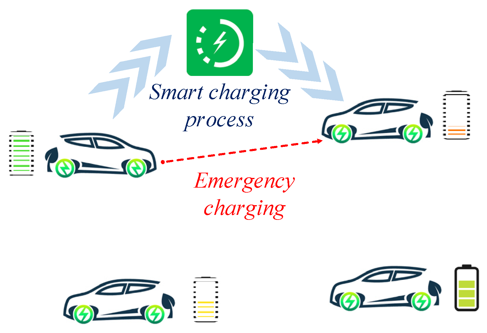
In this paper, an Emergency EV-to-EV Portable Battery Charger (EPBC) is proposed as a cost-effective solution for charging EVs on-the-road. The concept of EPBC system is depicted in Figure 1. In this user-friendly smart charger, each EV can share 5–15% of the stored energy in the battery to support other EVs in emergency mode. In the proposed smart charger, the output voltage and the injected current to the EVs are regulated simultaneously. To realize the smart charger, a nonlinear integral backstepping control (MF-NIBC) based on deep reinforcement learning (DRL) is implemented for stabilization of the studied electric vehicle system. The real-time examinations are conducted on the OPAL-RT platform to ascertain the applicability of the proposed MF-NIBC controller.
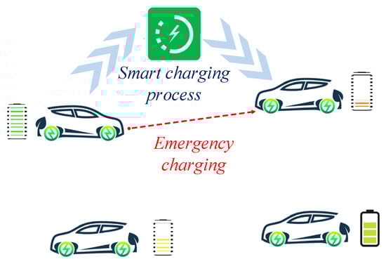
Figure 1.
Concept of the EV-to-EV Portable Battery Charger.
The rest of this article is structured as follows: in Section 2, the power structure of the proposed EPBC consisting of a bidirectional dual active bridge (DAB) dc-dc converter is described. The design of the MF-NIBC designed by DRL is presented in Section 3. In Section 4, the real-time results based on the three scenarios are presented to validate the proposed controller. Finally, Section 5 concludes the paper.
2. Power Structure of the Proposed EPBC
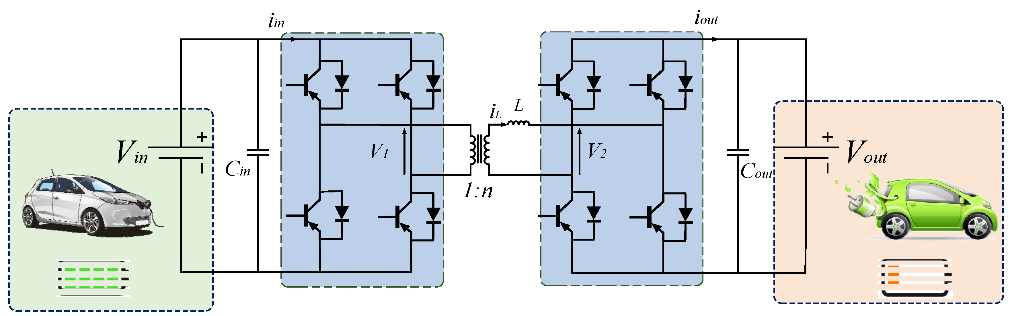
Figure 2 illustrates the power structure of the proposed EPBC in which a bidirectional dual active bridge (DAB) dc-dc converter is employed. The DAB topology for dc-dc converter has several advantages such as high efficiency, high performance, inherent soft-switching feature, high power density, and galvanic isolation [19]. Moreover, the DAB can provide bidirectional power flow, which permits flexible interfacing to other energy storage devices.
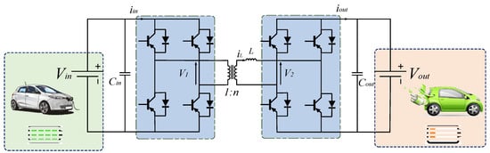
Figure 2.
Power structure of the proposed EPBC with the DAB dc-dc converter.
The DAB dc-dc converter contains two full-bridge circuits which are connected through a coupling inductor and an isolation transformer. The coupling inductor can be provided by the transformer leakage inductance. Each bridge in the DAB dc-dc converter generates a square wave voltage in their related terminals. The control of the power flow from one dc source to another can be investigated by the proper setting of the coupling inductor; i.e., with the suitable phase shift between the two square waves.
As depicted in Figure 2, the voltages which are generated by the two bridges are represented as and , respectively. In addition, is the input current, is the current of the coupling inductor, and is the output current. To control power flow, the time delay between and is , where is the duty cycle and is the switching period.
Based on the voltage level of the batteries in the EVs, the proposed EPBC determines the suitable operation mode. Therefore, the DAB dc-dc converter should operate in the buck or boost mode. When the converter operates in the buck mode, the output current can be presented as follows:
where is the turns ratio of the transformer. From Equation (1) it can be observed that the output current of the EPBC can be controlled by setting a suitable duty cycle.
Moreover, in the boost mode, the output current of the converter can be expressed as follows:
More details about the operation states of the DAB dc-dc converter can be found in [20].
Here, the small signal model and the linearized transfer function are derived to perform the dynamic and stability analysis. Figure 2 can be simplified as illustrated in Figure 3, where represents the internal resistance of the source. The small signal model of the simplified model of DAB can be expressed as follows [21]:
where is the relative percentage of phase shift variation between the two square waves. The variation of the phase shift duty ratio can affect the output voltage ripple as follows:
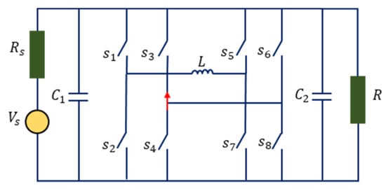
Figure 3.
Simplified circuit of DAB dc-dc converter.
Equation (4) indicates that by proper control of d, the stability of the DAB can be guaranteed and the fast dynamic response and zero steady-state error can be regulated. More details about the stability analysis of the DAB dc-dc converter can be found in [21].
In the next section, the procedure of the controller design is presented.
3. Design of Novel Assorted Nonlinear Controller Based on Deep Reinforcement Learning
The main control objective is to control the system of the studied EPBC with the DAB dc-dc converter with fast dynamic reaction and zero steady state error. In this section, a model free nonlinear integral backstepping control (MF-NIBC) approach based on a deep reinforcement learning (DRL) algorithm is suggested. The fundamental concept of Lyapunov theory is adopted to analyze the stability of the MF-NIBC applied to the power converter system.
3.1. Formulation of Model Free-Integral Backstepping Control (MF-NIBC) Approach
The following nonlinear dynamics can illustrate the system of the presented EPBC with the DAB dc-dc converter:
where is the extracted system dynamic, is the input of system, and is the unknown scaling factor.
By describing and as the uncertainties and un-modeled time-varying dynamics of the proposed EPBC and the estimate of the unknown scaling of parameter , Equation (5) can be rewritten as:
where is characterizing the order of the estimated model. Therefore, can be explained as follows:
An ultra-local model that is continually restructured could express the input-output relation of the suggested EPBC system to diminish specific state variables’ errors as in [15]:
where is a continually updated function that describes the time-varying general dynamics of the battery charger system (). It can also be estimated to attenuate the noise constructed from the derivative However, the approximation value is credible for a short time interval and it must update frequently. Therefore, the general formulation of the model-free control (MFC) input can be expressed as:
where is the feedback controller’s input, and is the derivative of the objective trajectory. Equation (9) demonstrates that the model-free and feedback controllers should work jointly to change the control input based on the uncertainties of the system parameters. By substituting Equation (9) in Equation (8), we have [14]:
It is clear that there is an error between the desired and the actual values of each state variable. Therefore, the function of error is defined as:
Combining Equations (10) and (11) yields:
where is the derivative of Equation (11). Note that must be designated to generate a linear differential equation converging to the aimed trajectory asymptotically.
The state variable of the system of the presented EPBC with the DAB dc-dc converter can be shown as follows:
The main purpose of MF-NIBC is the position tracking error convergence of a specific state variable and the convergence of the velocity tracking error related to that particular state. Therefore, to ensure the stability of the presented nonlinear EPBC by error tracking convergence, the well-known Lyapunov function is employed. In the first step, the positive definite Lyapunov function is established around the desired state variable as follows:
By differentiating Equation (15), we have:
There is an error between and its desired value () because is not the system control input. Hence, to compensate the dynamics error, the velocity tracking error is formulated as follow:
If the Lyapunov function is selected properly, the system error will converge to zero. To achieve this, the Lyapunov function is determined as semi-negative, .
The input can be shown as:
The suggested EPBC system uncertainties and the modeling error can generate a steady-state error. This error can disrupt the controller performance. Hence, the integral term shown below is employed to remove the steady-state error in the proposed controller:
As a consequence, the derivative of the position and velocity tracking errors can be explained as:
The Lyapunov function and can be developed for the position and velocity tracking error and characterized as follows [14]:
Under Lyapunov theory, the can be converging to zero by choosing the as a semi-negative definite.
Hence, can be formulated as follows:
Finally, by substituting Equation (29) into Equation (28), the control law for the system of the presented EPBC with the DAB dc-dc converter can be extracted as [14,22]:
According to the control law of (Equation (30)), the control structure of NIB-MFC is depicted in Figure 4.
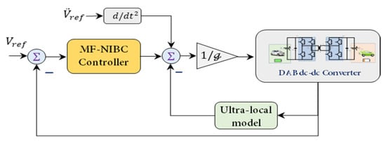
Figure 4.
Structure of NIB-MFC loop control.
Since the efficiency of the proposed MF-NIB controller depends on the controller parameters, these coefficients are designed by the deep deterministic policy gradient methodology (DDPG).
3.2. Deep Deterministic Policy Gradient Methodology
The DDPG algorithm is an actor-critic technique in a model-free framework which combines the benefits of a deterministic policy gradient (DPG) and a Deep Q Network (DQN). In the DQN, the Q-function in Q-learning is approximated by deep neural network (DNN) with continuous data while the DQN-agent adopts Epsilon-Greedy policy with discrete actions. The states are related deterministically to a particular action in the DPG by parameterizing the actor DNN, where the weight coefficients of the actor are updated by the performance of the gradient of the policies. The DDPG algorithm is made from four deep neural networks including main actor and critic, and their target networks. In the DDPG algorithm, the training of the critic network is conducted to replace the Q-table by adopting deep neural networks, while the training of the actor network is realized to produce a deterministic policy [23,24].
In a policy gradient, the performance of agents depends on the policy , where the states are mapped to actions based on a probability distribution. By considering the action and state under a deterministic policy of actions , the Q-table is defined by the following Bellman equation [25]:
where denotes the reward function, denotes the discount factor, and denotes the expectation distribution.
For a random stochastic policy , it is expected that the Bellman equation can be approximated by deep neural networks . The updating loss of the critic network is computed by:
In the loss function, denotes the state distribution under the policy of , is the weight parameter of deep Q-network, and is defined by:
By the aid of the critic network, the policy of the actor network is updated by the following gradient:
where denotes the weight parameter of actor DNN.
A replay buffer is implemented in the DDPG to remove the correlations between samples as well as to enhance the stability of training by separating the target DNNs (, ). In addition, some noise is added to the actions for exploration purposes, i.e., . In addition, the target networks of critic and actor are updated by [25]:
The procedure code of the DDPG algorithm is depicted in Algorithm 1.
| Algorithm 1: Procedure of the DDPG algorithm. |
| 1: Randomly initialize critic and actor networks with weights and 2: Initialize target networks and with weights , 3: Set up empty replay buffer 4: for episode = to do 5: Begin with an Ornstein-Uhelnbeck (OU) noise for exploration 6: Receive initial observation state 7: for t = to do 8: Apply action to environment 9: Observe next state and reward 10: Store following transitions into replay buffer 11: Sample random minibatch of transitions from 12: Set 13: Update critic by the loss: 14: Update the actor policy using the sampled policy gradient: 15: Update the target networks: 16: end for 17: end for |
3.3. Optimizing the Key Coefficients of MF-NIBC
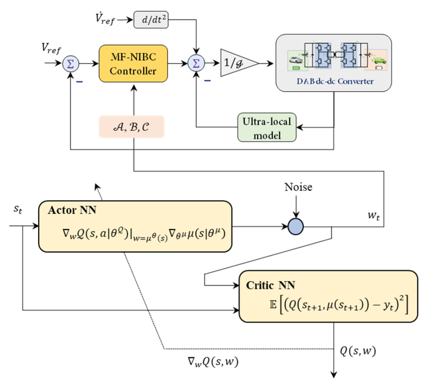
Some parameters are embedded in the structure of the MF-NIBC controller which should be appropriately adjusted to regulate the output of the DAB dc-dc converter. The terms of , and are the key parameters in the law control of MF-NIB (Equation (30)) which will be adjusted by the DDPG algorithm. The overall structure of the proposed DDPG based MF-NIB controller is depicted in Figure 5.

Figure 5.
Structure of MF-NIB controller designed by the DDPG algorithm.
In this application, the terms of the output voltage and the tracking error , the delay of (), the delay of the voltage error (), and the derivative values of and are considered as the system states,. The deep neural networks of the DDPG-agent are trained to suppress the fluctuations in output voltage in the power electronic test-system by maximizing the reward function. The reward signal is defined as:
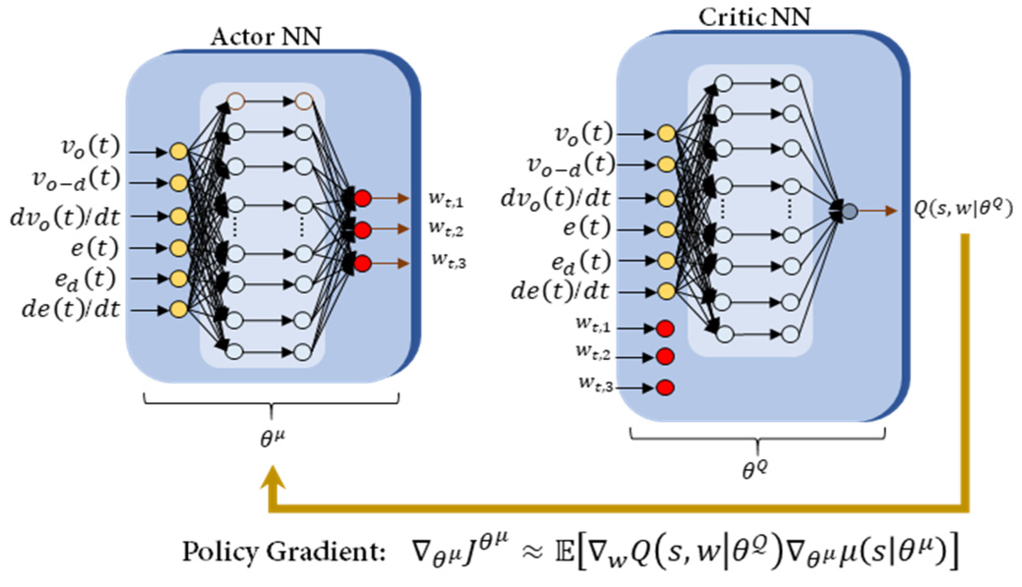
where and are the reward penalty, and is the defined deviation of the output voltage from the nominal value. Utilizing the capability of the neural networks, the DDPG agent tunes the control parameters in such a way that stabilizes the output voltage by maximizing a reward signal. The structure of deep neural networks of DDPG algorithm has been depicted in Figure 6.
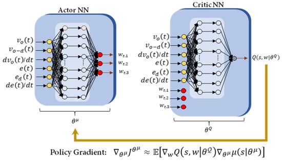
Figure 6.
Actor critic framework of the DDPG algorithm.
4. Performance Evaluation
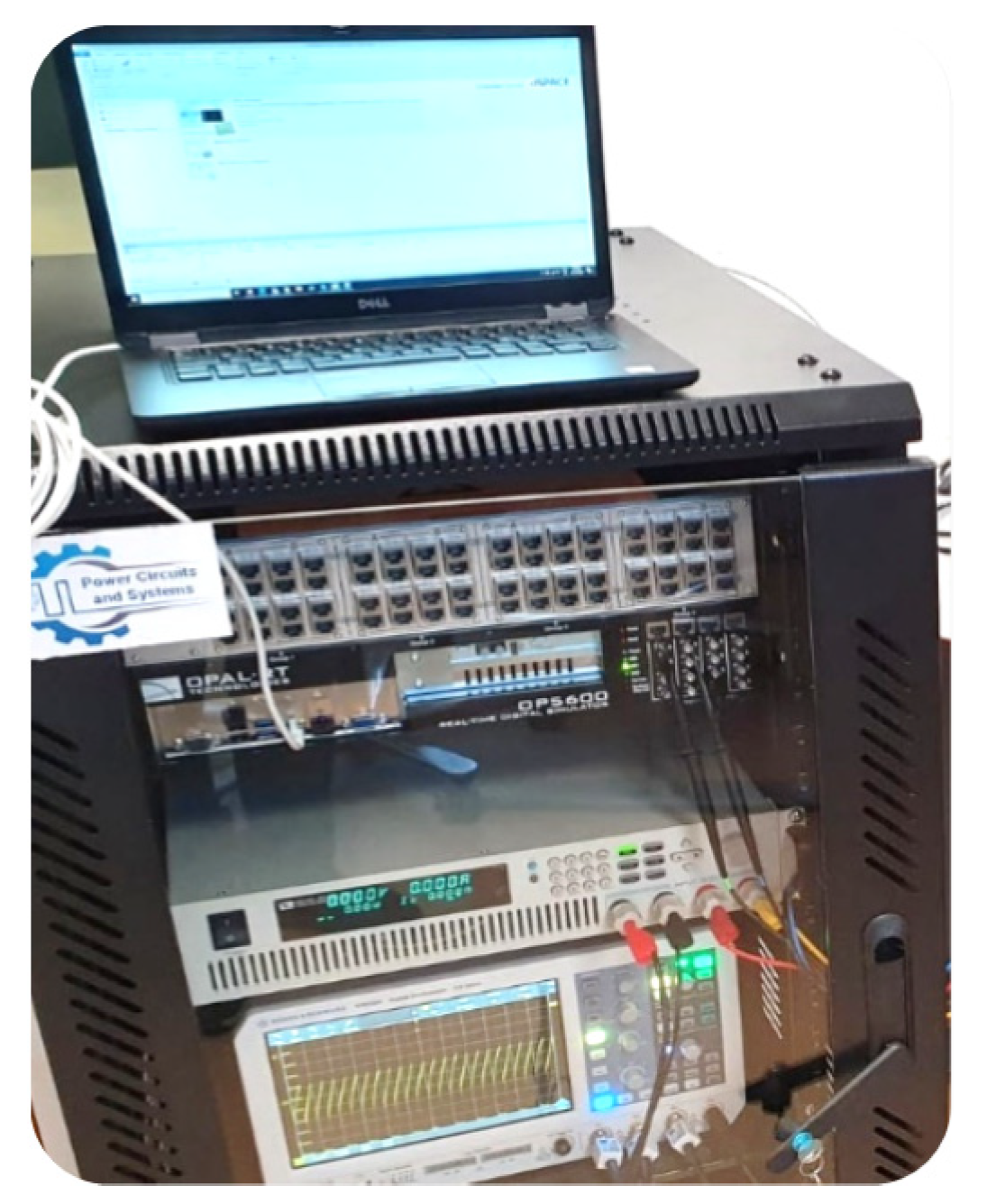
To validate the effectiveness of the proposed controller and the performance of the smart charger, the real-time results are discussed in this section. The setup tests based on the OPAL-RT are represented in Figure 7. The electrical parameters of the suggested EV smart charger are listed in Table 1, and the controller parameters are listed in Table 2. In order to investigate the applicability of the proposed Emergency EV-to-EV battery charger (EPBC), several conditions can be assumed based on the electrical specification of the EV’s battery. For this purpose, three scenarios can be studied based on the voltage of the battery.

Figure 7.
The Real-time setup of the SEFPC based on OPAL-RT.

Table 1.
Parameters of the EPBC.
Table 2.
Parameters of the controllers.
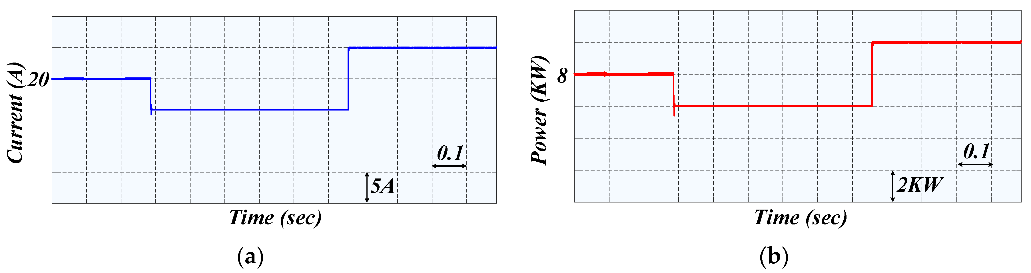
Case1: In the first scenario, it is assumed that the batteries in both EVs are the same. Therefore, the voltage in the input and output of the DAB dc-dc converter is 400 V and the nominal current is 20 A. In this situation, the output current of the DAB dc-dc converter is controlled to set the proper value and speed of the charging process. In the emergency mode, as shown in Figure 8a, the maximum current of the converter is controlled to be 25 A at 400 V. In this condition, the maximum value of transferred energy is limited to 15% of the capacity of the battery. Moreover, the minimum amount of current that can be transferred from one EV to another EV is limited to 15 A.
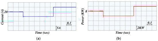
Figure 8.
Real-time results for the power changes in the emergency charging mode in the proposed EPBC: (a) output current, (b) output power.
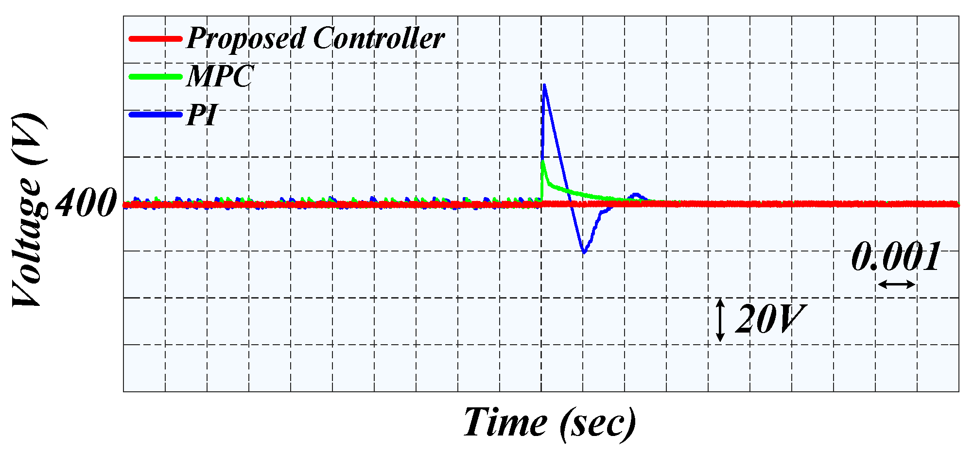
Figure 8a,b shows the step change of the output current and output power of the proposed EPBC, respectively. The output voltage of the proposed charger is shown in Figure 9. In order to demonstrate the performance of our proposed charger with the novel suggested MF-NIBC controller, a comparison with the MPC controller and the conventional PI controller is carried out. From Figure 9, it can be observed that the proposed controller has a better transient response and can guarantee the stability of the output voltage of the DAB dc-dc converter. Moreover, controlling the output current can be realized at the same time.
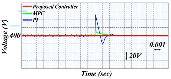
Figure 9.
Comparison of the voltage transient responses of the proposed MF-NIBC controller, MPC, and the conventional PI controller during a step change in the output power in the first scenario.
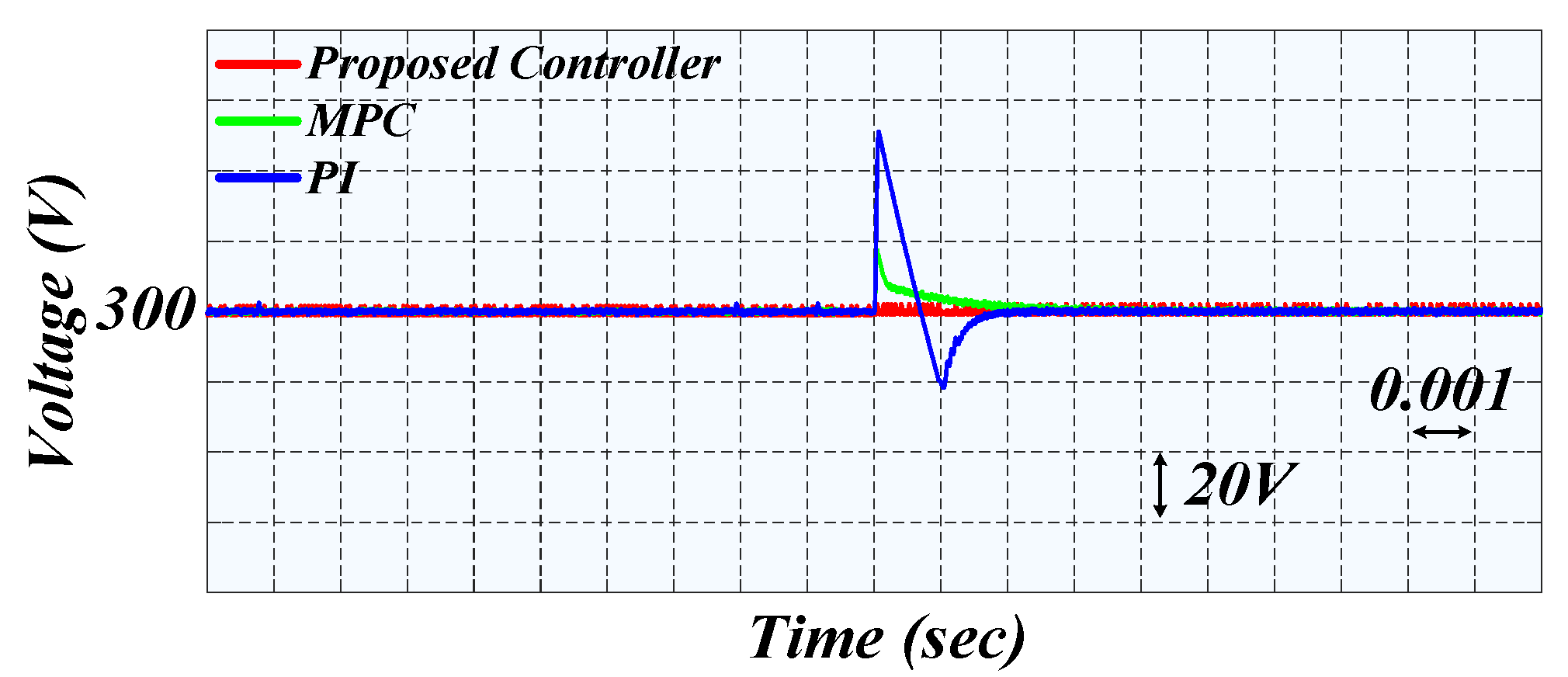
Case2: In the second scenario, the batteries in the EVs are considered different. It means that the nominal voltage of the EV which injects the power to the other one is 400 V; the nominal voltage of the second EV which receives the energy is assumed to be 300 V. Here, the maximum and minimum values of the injected current in the emergency charging mode are 25 A and 15 A, respectively. In order to prove the superiority of the MF-NIBC controller against other controllers, the transient outcomes of the output voltage of the proposed charger are shown in Figure 10. It can be concluded from Figure 10 that the MF-NIBC controller provides the fastest transient response over other controllers, which means the suggested method can guarantee the voltage stability and provides proper regulation of the output voltage and current simultaneously.
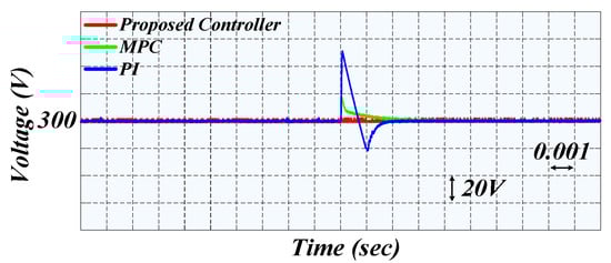
Figure 10.
Comparison of the voltage transient responses of the proposed MF-NIBC controller, MPC, and the conventional PI controller during a step change in the output power in the second scenario.
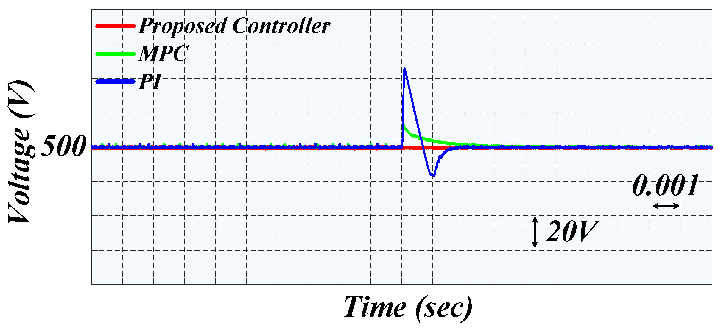
Case3: In the last scenario, it is assumed that the nominal voltage of the second EV is 500 V, whereas the voltage of the EV which acts as a source is 400. As mentioned previously, since the EPBC works in emergency mode, it is allowed to transfer up to 15% of the capacity of the battery. Therefore, as depicted in Figure 8a, the injected current is limited between upper and lower predefined values. Figure 11 expresses the transient outcomes of the proposed MF-NIBC controller, MPC controller, and PI controller. With the help of the suggested MF-NIBC controller, Figure 11 indicates that our suggested smart charger has a reliable performance with the lowest overshoot compared to the traditional controller.
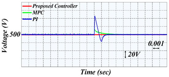
Figure 11.
Comparison of the voltage transient responses of the proposed MF-NIBC controller, MPC, and the conventional PI controller during a step change in the output power in the third scenario.
5. Conclusions
In this paper, an Emergency EV-to-EV Portable Battery Charger (EPBC) was developed for charging EVs in emergency mode on-the-road. The proposed smart charger can share up to 15% of the stored energy while taking into consideration the state of charge (SOC), capacity, and important technical specifications of the EV’s battery. By using a bidirectional dual active bridge (DAB) dc-dc converter, the proposed EPBC can regulate the output voltage and the injected current to the EV simultaneously. To achieve smart charging prosses with the proposed EPBC, a model free nonlinear integral backstepping control (MF-NIBC) was implemented to regulate the output voltage of the EPBC. Moreover, in order to adjust the MF-NIBC controller, a deep deterministic policy gradient (DDPG) was employed by utilizing the actor and critic networks. Real-time results based on the OPAL-RT setup were carried out to validate the feasibility and performance of the proposed EPBC. In future work, the exchanged energy, and the conversion efficiency should be analyzed in a long-term examination. Moreover, the temperatures experienced by both batteries should be investigated with consideration of the effect of the transfer on the evolution of temperature.
Author Contributions
Data curation, M.M. and A.F.; Methodology, M.G.; Software, H.F.; Supervision, M.H.K. All authors have read and agreed to the published version of the manuscript.
Funding
This research received no external funding.
Conflicts of Interest
The authors declare no conflict of interest.
References
- Iyer, V.M.; Gulur, S.; Gohil, G.; Bhattacharya, S. Extreme fast charging station architecture for electric vehicles with partial power processing. In Proceedings of the 2018 IEEE Applied Power Electronics Conference and Exposition (APEC), San Antonio, TX, USA, 4–8 March 2018; IEEE: Piscataway, NJ, USA, 2018; pp. 659–665. [Google Scholar]
- Fuinhas, J.A.; Koengkan, M.; Leitão, N.C.; Nwani, C.; Uzuner, G.; Dehdar, F.; Relva, S.; Peyerl, D. Effect of Battery Electric Vehicles on Greenhouse Gas Emissions in 29 European Union Countries. Sustainability 2021, 13, 13611. [Google Scholar] [CrossRef]
- Gryparis, E.; Papadopoulos, P.; Leligou, H.C.; Psomopoulos, C.S. Electricity demand and carbon emission in power generation under high penetration of electric vehicles. A European Union perspective. Energy Rep. 2020, 6, 475–486. [Google Scholar] [CrossRef]
- Asna, M.; Shareef, H.; Achikkulath, P.; Mokhlis, H.; Errouissi, R.; Wahyudie, A. Analysis of an Optimal Planning Model for Electric Vehicle Fast-Charging Stations in Al Ain City, United Arab Emirates. IEEE Access 2021, 9, 73678–73694. [Google Scholar] [CrossRef]
- Tu, H.; Feng, H.; Srdic, S.; Lukic, S. Extreme fast charging of electric vehicles: A technology overview. IEEE Trans. Transp. Electrif. 2019, 5, 861–878. [Google Scholar] [CrossRef]
- Krishna, G. Understanding and identifying barriers to electric vehicle adoption through thematic analysis. Transp. Res. Interdiscip. Perspect. 2021, 10, 100364. [Google Scholar] [CrossRef]
- Sheng, K.; Dibaj, M.; Akrami, M. Analysing the Cost-Effectiveness of Charging Stations for Electric Vehicles in the UK’s Rural Areas. World Electr. Veh. J. 2021, 12, 232. [Google Scholar] [CrossRef]
- Li, Y.; Li, L.; Peng, C.; Zou, J. An MPC based optimized control approach for EV-based voltage regulation in distribution grid. Electr. Power Syst. Res. 2019, 172, 152–160. [Google Scholar] [CrossRef]
- Ahmed, I.; Ahmad, I.; Ahmed, S.; Adil, H.M.; Adil, M. Robust nonlinear control of battery electric vehicle charger in grid to vehicle applications. J. Energy Storage 2021, 42, 103039. [Google Scholar] [CrossRef]
- Mallik, A.; Lu, J.; Khaligh, A. Sliding mode control of single-phase interleaved totem-pole PFC for electric vehicle onboard chargers. IEEE Trans. Veh. Technol. 2018, 67, 8100–8109. [Google Scholar] [CrossRef]
- Aboudrar, I.; El Hani, S.; El Harouri, K.; Martins, J.; Goncalves, R.J. Reactive Power Compensation by ADRC in Vehicle to Grid Application during Grid Fault Conditions. In Proceedings of the 2020 International Conference on Electrical and Information Technologies (ICEIT), Rabat, Morocco, 4–7 March 2020; pp. 1–6. [Google Scholar]
- Song, J.; Fu, C.; Zhang, G.; Duan, B.; Zhang, C. Backstepping Control of High-Frequency Link Matrix Rectifier for Battery Chargers. IEEE Trans. Power Electron. 2021, 36, 10801–10814. [Google Scholar] [CrossRef]
- Chang, M.; Bae, S.; Cha, G.; Yoo, J. Aggregated Electric Vehicle Fast-Charging Power Demand Analysis and Forecast Based on LSTM Neural Network. Sustainability 2021, 13, 13783. [Google Scholar] [CrossRef]
- Younes, Y.A.; Drak, A.; Noura, H.; Rabhi, A.; Hajjaji, A.E. Robust model-free control applied to a quadrotor UAV. J. Intell. Robot. Syst. 2016, 84, 37–52. [Google Scholar] [CrossRef]
- Glida, H.E.; Abdou, L.; Chelihi, A.; Sentouh, C.; Hasseni, S.-E.-I. Optimal model-free backstepping control for a quadrotor helicopter. Nonlinear Dyn. 2020, 100, 3449–3468. [Google Scholar] [CrossRef]
- Gheisarnejad, M.; Faraji, B.; Esfahani, Z.; Khooban, M.-H. A Close Loop Multi-Area Brain Stimulation Control for Parkinson’s Patients Rehabilitation. IEEE Sens. J. 2019, 20, 2205–2213. [Google Scholar] [CrossRef]
- Zeitouni, M.J.; Parvaresh, A.; Abrazeh, S.; Mohseni, S.-R.; Gheisarnejad, M.; Khooban, M.-H. Digital Twins-Assisted Design of Next-Generation Advanced Controllers for Power Systems and Electronics: Wind Turbine as a Case Study. Inventions 2020, 5, 19. [Google Scholar] [CrossRef]
- Gheisarnejad, M.; Khooban, M. Supervised control strategy in trajectory tracking for a wheeled mobile robot. IET Collab. Intell. Manuf. 2019, 1, 3–9. [Google Scholar] [CrossRef]
- Feng, H.; Teng, F.; Montes, O.A.; Awal, M.A.; Bipu, M.R.H.; Husain, I.; Lukic, S. Passive Capacitor Voltage Balancing of SiC-Based Three-Level Dual-Active-Bridge Converter Using Hybrid NPC-Flying Capacitor Structure. IEEE Trans. Power Electron. 2021, 37, 4183–4194. [Google Scholar] [CrossRef]
- Naayagi, R.; Forsyth, A.J.; Shuttleworth, R. High-Power Bidirectional DC–DC Converter for Aerospace Applications. IEEE Trans. Power Electron. 2012, 27, 4366–4379. [Google Scholar] [CrossRef]
- Bai, H.; Nie, Z.; Mi, C.C. Experimental comparison of traditional phase-shift, dual-phase-shift, and model-based control of isolated bidirectional DC–DC converters. IEEE Trans. Power Electron. 2009, 25, 1444–1449. [Google Scholar] [CrossRef]
- Al Younes, Y.; Drak, A.; Noura, H.; Rabhi, A.; El Hajjaji, A. Nonlinear Integral Backstepping—Model-Free Control Applied to a Quadrotor System. Proc. Int. Conf. Intell. Unmanned Syst. 2014, 10, 1–6. [Google Scholar]
- Qiu, C.; Hu, Y.; Chen, Y.; Zeng, B. Deep deterministic policy gradient (DDPG)-based energy harvesting wireless communications. IEEE Internet Things J. 2019, 6, 8577–8588. [Google Scholar] [CrossRef]
- Gheisarnejad, M.; Farsizadeh, H.; Tavana, M.-R.; Khooban, M.H. A Novel Deep Learning Controller for DC–DC Buck–Boost Converters in Wireless Power Transfer Feeding CPLs. IEEE Trans. Ind. Electron. 2020, 68, 6379–6384. [Google Scholar] [CrossRef]
- Wei, Z.; Quan, Z.; Wu, J.; Li, Y.; Pou, J.; Zhong, H. Deep deterministic policy gradient-drl enabled multiphysics-constrained fast charging of lithium-ion battery. IEEE Trans. Ind. Electron. 2021, 69, 2588–2598. [Google Scholar] [CrossRef]


Publisher’s Note: MDPI stays neutral with regard to jurisdictional claims in published maps and institutional affiliations. |
© 2022 by the authors. Licensee MDPI, Basel, Switzerland. This article is an open access article distributed under the terms and conditions of the Creative Commons Attribution (CC BY) license (https://creativecommons.org/licenses/by/4.0/).