1. Introduction
Food security is one of the main concerns in modern society in the twenty-first century. People generally eat food to avoid hunger. Although some chemicals in food ingredients are allowed within strict limitations, a heavy penalty, legislated by the various governments, is applied to those people or companies that disobey the policies. Sometimes people eat specific food just from their desire to stay healthy. Certain health foods are announced to be good for the human body and then the price becomes very high. Dishonest merchants make fake health food and sell it in public markets to earn money. Fake health food may cause no definite harm to human bodies, but some can easily cause health problems and/or severe harm to certain people.
Gelatinous Chinese medicines (GCMs) are very popular animal-derived medicines used in traditional Chinese medicine (TCM) clinics to treat dizziness, palpitations, and insomnia [
1]. In recent decades, due to a large demand for GCMs, bovine or swine skin was often used to make fake or adulterated
Asini Corii Colla (ACC; donkey-hide glue), which is one of the most valuable tonic traditional Chinese medicines [
2]. This situation exposes the public to a high health risk and causes unfair competition in the commercial markets. Therefore, it is significantly important to establish a reliable and convenient testing technology, develop an accurate detection method and identify the fake health food before it can be used.
The bacterial culture method is considered the gold standard for the diagnosis of pathogens in clinical practice for food security. It is very specific and is certainly accurate. However, it is also time-consuming, complex, and without high sensitivity [
3]. Various spectroscopy-based, immunological and chromatographic methods have also been studied for the quality control of animal-derived Chinese medicines [
4,
5]. An alternative method for highly specific analysis in species identification is the nucleic acid-based assay [
6], which became popular during the last few decades.
In well-resourced areas, the detection process utilizes regular assays, and these are usually performed on a standard laboratory platform. However, the medical resources in remote areas are not necessarily enough. Such laboratory work cannot be supported immediately, and then a portable detection system is the most appropriate way to solve these difficult situations. Point-of-Care (PoC) diagnostics are commonly based on portable, inexpensive, and user-friendly sensor platforms, and allow the sensitive, robust, and real-time detection of biotargets. For food security issues, PoC diagnostics can detect a specific target presence on-site and are one of the most effective ways to solve the problem.
After the polymerase chain reaction (PCR) was invented more than 30 years ago, nucleic acid amplification was able to increase detection sensitivity and specificity, and has become one of the most useful and reliable techniques in molecular diagnostics [
7]. Though PCR is a widely used technology, the temperature cycling during the amplification process increases the system cost and complicates the operating procedure. Various isothermal nucleic acid amplification methods have been proposed since the beginning of the 21st century, so that laboratories can reduce the manufacturing cost and simplify the overall design of the platform.
Loop-mediated isothermal amplification (LAMP), which relies on the
Bst (
Bacillus stearothermophilus) polymerase with strand displacement activity [
8], is an isothermal gene amplification method of target deoxyribonucleic acid (DNA). It is a single-step amplification reaction that requires four or six primers specific to certain separate sequences within the target region. Compared to PCR, it is not necessary to extract DNA to be highly purified before the LAMP process, and minimal inhibition is observed during LAMP [
9], suggesting its potential applications for the PoC platform. For the identification of
Asini Corii Colla, the LAMP assay did not interfere with the mixing of donkey DNA and adulterant genomic DNA. The relative detection limit was 0.1% of donkey-hide gelatine (DHG) in the adulterants [
2].
A commercial thermocycling machine normally contains a thermal control module and several reaction chambers, which support a proper environment for utilizing nucleic acid-based amplification approaches. The miniaturization of thermocycling devices introduces the possibilities of using a diverse choice for PoC diagnostics. Previous works regarding miniaturized LAMP devices have utilized various heating apparatuses, such as Peltier elements [
10], thin film resistors [
11,
12], cartridge heaters [
13], infrared sources [
14], and so forth. A single-use disposable heater was used by Curtis et al. [
15]. Initiated by adding some saline to magnesium iron fuel powder, the electricity-free heating device releases the heat from a chemical reaction for LAMP technologies. Tsougeni et al. [
16] presented an integrated platform for pathogen analysis in food samples. A printed circuit board, where two resistive heaters were fabricated, was utilized to support the required temperature for DNA amplification through Joule heating.
There are several DNA detection methods for LAMP used in portable devices. Hataoka et al. [
17] integrated LAMP and the electrophoresis detection of prostate-specific antigen (PSA) cDNAs on poly(methyl methacrylate) (PMMA) microfluidic chips. Lee et al. [
18] utilized the PMMA micro-reactor to implement the LAMP reaction. Concentrations of the hepatitis B virus (HBV) were quantified by a spectrometer at an excitation light. Chuang et al. [
19] demonstrated the detection of the HBV DNA template during LAMP with the surface plasmon resonance (SPR) analytical method. Luo et al. [
20] combined the merits of LAMP and electrochemistry methods to develop a microfluidic system. The etched ITO glass and PDMS microchips were utilized to monitor different pathogens in real time.
Fluorescence detection is the most common method used to detect the number of DNA fragments during or after the amplification process [
21]. For the fluorescence imaging system, the CCD camera [
22], photodiode [
23] and fluorescence microscope [
24] used an LED as the excitation light and imaged the reaction chambers in previous studies. Ma et al. [
25] developed an arrayed emulsion droplet device for digital LAMP detection. Calcein was used as the fluorescent dye for the detection of DNA products. Gurrala et al. [
26] provided a LAMP platform that can detect changes in pH values generated by on-chip nucleic acid amplification. The hydrogen ions produced during DNA polymerization were detected and quantified using the SYBR green dye. Phaneuf et al. [
27] demonstrated the simultaneous measurement of both Cas9 protein and activity in a single sample using the fluorescence detection system. A visualization approach to Cy5 labeling was based on a photomultiplier tube (PMT) module with a laser diode for light excitation.
Due to the cell phone’s pervasion, low cost, ease of use, and breadth of flexible integration, certain researchers utilized cell phones to detect the amount of nucleic acid during the amplification or at the endpoint. Chen et al. [
28] utilized a smartphone camera to perform a determination of target DNA sequences in approximately 30 min. The detection system for performing LAMP-based amplifications made the detection of multiple targets possible at the same time. Song et al. [
29] designed a smartphone-based detection platform for quantitative molecular diagnostics. An Android app was developed for optical signal monitoring, analysis and transmission. Ye et al. [
30] used the Android platform to access the control module via RS-232 for DNA detection information. The optical module was used to collect SYBR green fluorescence signals. Shah et al. [
31] presented a device that images two fluorophores using mobile phones, which enables real-time DNA detection. Multipass excitation and emission filters were attached to the flash and camera of multiple mobile phone models.
With regard to previous studies about the construction of the thermal control module, the DNA fragments were amplified at a constant temperature during the LAMP process by electricity-free or electric heating methods, and no cooling elements were required. Some phase change materials (PCMs) inside the LAMP device were used to passively control the mixture’s temperature, for simplicity of the system integration. The temperature of the reaction chamber was kept at a constant value, while the PCMs absorbed large amounts of latent heat and went through the solid phase, changing to the liquid phase. In the LAMP device with an active thermal control, the rising time and the residence time in which a sample is raised to a stable temperature and exposed to an isothermal environment are determined by the arrangement of heaters rather than by the melting process, as required by PCMs. In order to further enhance the heat transfer behavior of active heating elements, fluids including suspended nanomaterials were used to result in higher convection than single-phase fluids in heat exchangers [
32,
33,
34,
35]. This has the benefit of rapid thermal control, compared with the passive heating module.
To date, a LAMP assay targeting Asini Corii Colla DNA has been reported. However, the LAMP detection of the Asini Corii Colla DNA has not been demonstrated for on-site food security. For the quantitative analysis of DNA by using the LAMP reaction, we demonstrate a portable DNA analysis device and show that real-time detection can be accomplished using a commercial smartphone. With the integration of one cartridge heater onto the aluminum chamber, a stable temperature for the isothermal amplification can be generated within 5 min and is easy to regulate. Finally, the results show that sensitivity of the device is achieved, and a segment of Asini Corii Colla DNA is amplified successfully in the portable LAMP system.
2. Experimental Method
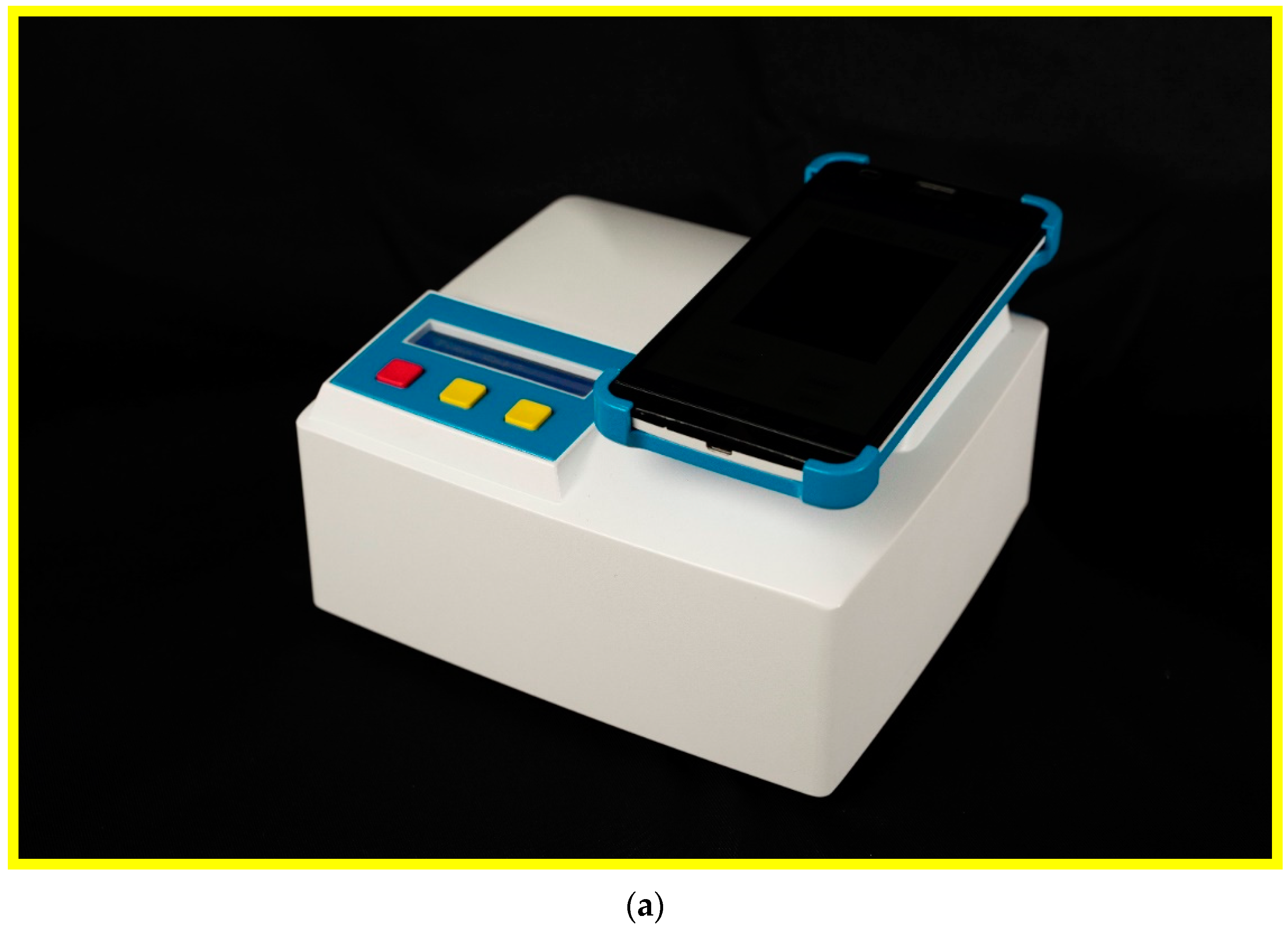
The real-time LAMP detection system (shown in
Figure 1a) consists of three individual parts, including the main structure for housing all the electronic elements and the rectangular reaction chamber, one thermal module for controlling the sample temperature, and a smartphone for detecting the DNA product (shown in
Figure 1b). The DNA mixture is injected into the PCR tube through the opening, and the tube is then inserted into the cavity of the aluminum reaction chamber. One cartridge heater is utilized to maintain the amplification temperature of the DNA mixture during the LAMP process. The stable temperature for DNA amplification is controlled by the microcontroller of the thermal module. After a designated time period, the final product is taken out of the chamber for further analysis. Alternatively, during that period, the DNA mixture is detected by a smartphone.
2.1. Design and Fabrication of the Reaction Chamber
The reaction chamber is fabricated from aluminum, using a computer numerically controlled (CNC) machine. The aluminum chamber is 20 mm × 43 mm × 30 mm in its outer dimensions, and the geometric shape of the sample volume inside the reaction chamber is fitted to the outline of a PCR tube of 0.2 mL. A cylinder with a diameter of 3.2 mm and a length of 42 mm is machined at the side wall of the chamber, for inserting a cartridge heater. Another specific cavity located under the cartridge heater is also machined for inserting an LM35 temperature sensor.
2.2. Heating Module and Temperature Sensing System
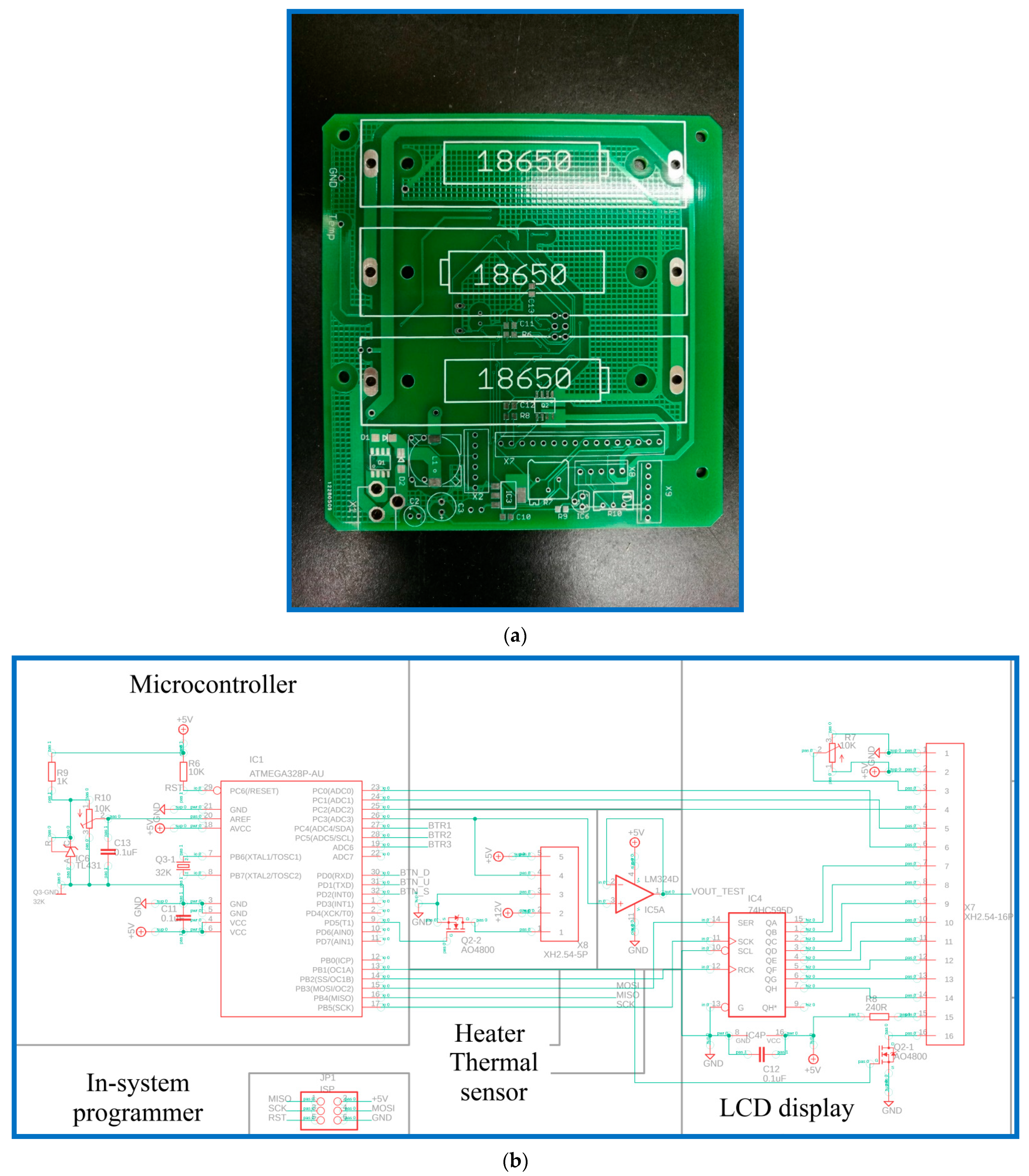
The heating module comprises an aluminum block, a cartridge heater, a thermal sensor, a DC power unit, and a homemade printed circuit board (PCB). The functions of the homemade PCB, shown in
Figure 2a, are composed of a microcontroller, heating module, sensing module, LCD display, power supply, and power recharger. The circuits and the PCB layout are created using Autodesk EAGLE software. The microcontroller in the PCB, as shown in
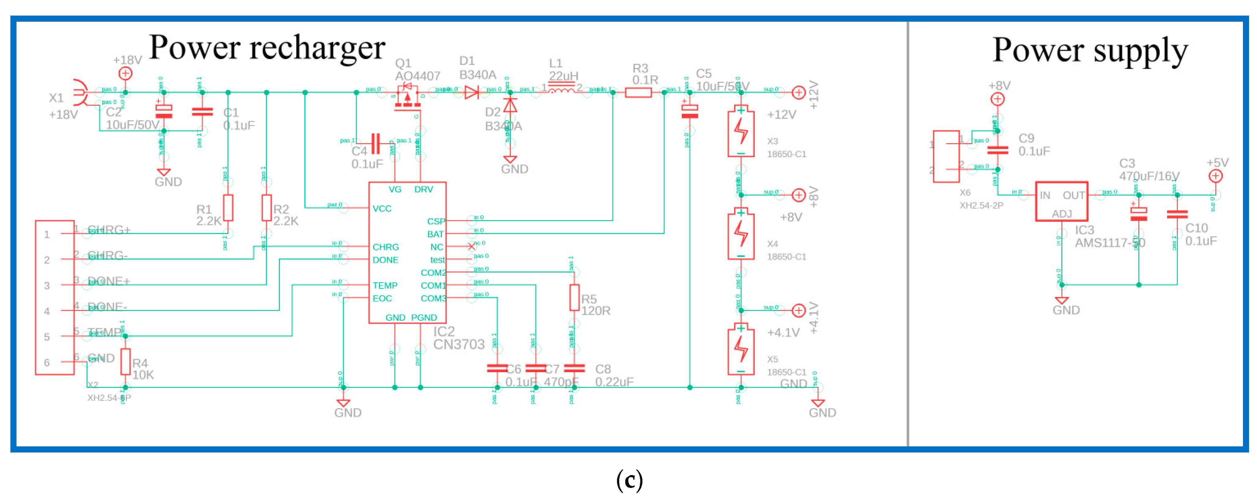
Figure 2b, is an ATmega328p-au microcontroller (Microchip Technology Inc., Chandler, AZ, USA). The in-system programmer (ISP) allows the programming and reprogramming of microcontrollers and communicates serially with the ATmega328p-au microcontroller. To heat the aluminum block, a metal oxide semiconductor field-effect transistor (MOSFET, AO4800) is used to control the heater. Using the operational amplifier (LM324D) and analog-to-digital converter (ADC), the temperature value corresponding to LM35 is obtained. Then, the LCD display is controlled using a 74HC595D shift register, and this provides the user interface. The power recharger part utilizes a lithium-ion battery charger controller (CN3703) for three serial-connected 18,650 batteries. The power supply part uses an AMS1117 fixed voltage regulator to provide up to 1 A of output current, as shown in
Figure 2c.
The heating block is equipped with two bores for housing a resistance cartridge heater (3.175 mm diameter, 38 mm length, 14 W, C1J-9412, Watlow, St. Louis, MO, USA), and a thermal analog sensor (LM35, Texas Instruments, Dallas, TX, USA). The high thermal conductivity of aluminum (205 W/m °C) ensures good temperature uniformity within the block. To prevent the thermal dissipation of the reaction block, the sidewalls are firmly attached by some rubber sheets of very low thermal conductivity (0.19 W/m °C), and the bottom is mounted onto a PMMA frame (0.167 W/m °C). Between the contact surfaces of the cartridge heater and the cylindrical hole in the block, some ceramic synthetic fluid thermal grease (10 W/m °C) is utilized as an interface to reduce the thermal resistance.
Atmel Studio 7, an integrated development environment (IDE), is utilized for developing the hardware offerings and applications. The ATmega328p-au microcontroller is programmed in the programming language, C++. The thermal sensor, which is inserted into the hole of the aluminum block, is connected to a homemade PCB. The microcontroller receives the temperature signal and determines the power input to the heater using a proportional/integral/derivative (PID) algorithm. After the introduction of the sample, the heater is programmed to maintain 60~65 °C (depending on the primers of the DNA mixtures). A DC power unit, supported by three serial-connected 18,650 batteries, is utilized to supply the power requirement when the system is working.
The measured temperature inside the sample mixture is compared with the setting temperature as input by the key-presses. Because of the spatial separation, the sensor temperature differs from the temperature inside the DNA mixture in the tube. Therefore, the temperature inside the tube is measured by using thermocouples inserted into the tube before the LAMP experiment and utilized to calibrate the sensor temperature in order to set the feedback control. The thermocouple (K30-2-506, Watlow), which is used to sense the sample temperature inside the chamber, is connected to a data acquisition system (NI 9211, National Instruments, Austin, TX, USA) that converts the analog signal to a digital one. A computer receives the temperature signals through the NI 9211 interface and records the real-time temperature profiles. The temperature within the DNA mixture is profiled whether or not the mixture is heated by the heater. After ensuring temperature accuracy, the DNA procedure is performed under the specified conditions.
2.3. Smartphone Detection
The smartphone-based detection module that provides the excitation flashlight, and collects the fluorescence emission from the LAMP reactions, is now presented. The smartphone rear-facing camera is positioned above the reaction tube and aligns the cap of the reaction tube with the plastic mechanical parts. An ultraviolet LED flashlight (wavelength 350–370 nm), powered by a single AAAA battery, is placed under the smartphone and shines a light toward the mixture tube. An inclined direction of the excitation light makes an angle of 45° with the horizontal plane. The plastic case inside serves as a dark environment for fluorescence detection by excluding the light from outside. The camera of the smartphone functions as a detector by capturing the image of the reaction chamber every 3 min. The smartphone processor acts as an image analyzer by processing the captured images in the mobile application (app).
The Android app was written with a Java development kit utilizing Android Studio. The app installed in the smartphone was developed for the Android operating system (OS) and was designed as a portable analysis device with a graphical user interface (GUI). The GUI permits users to adjust the operational parameters and monitor the LAMP reaction status in real time. When green fluorescence is observed, the sample is judged as positive.
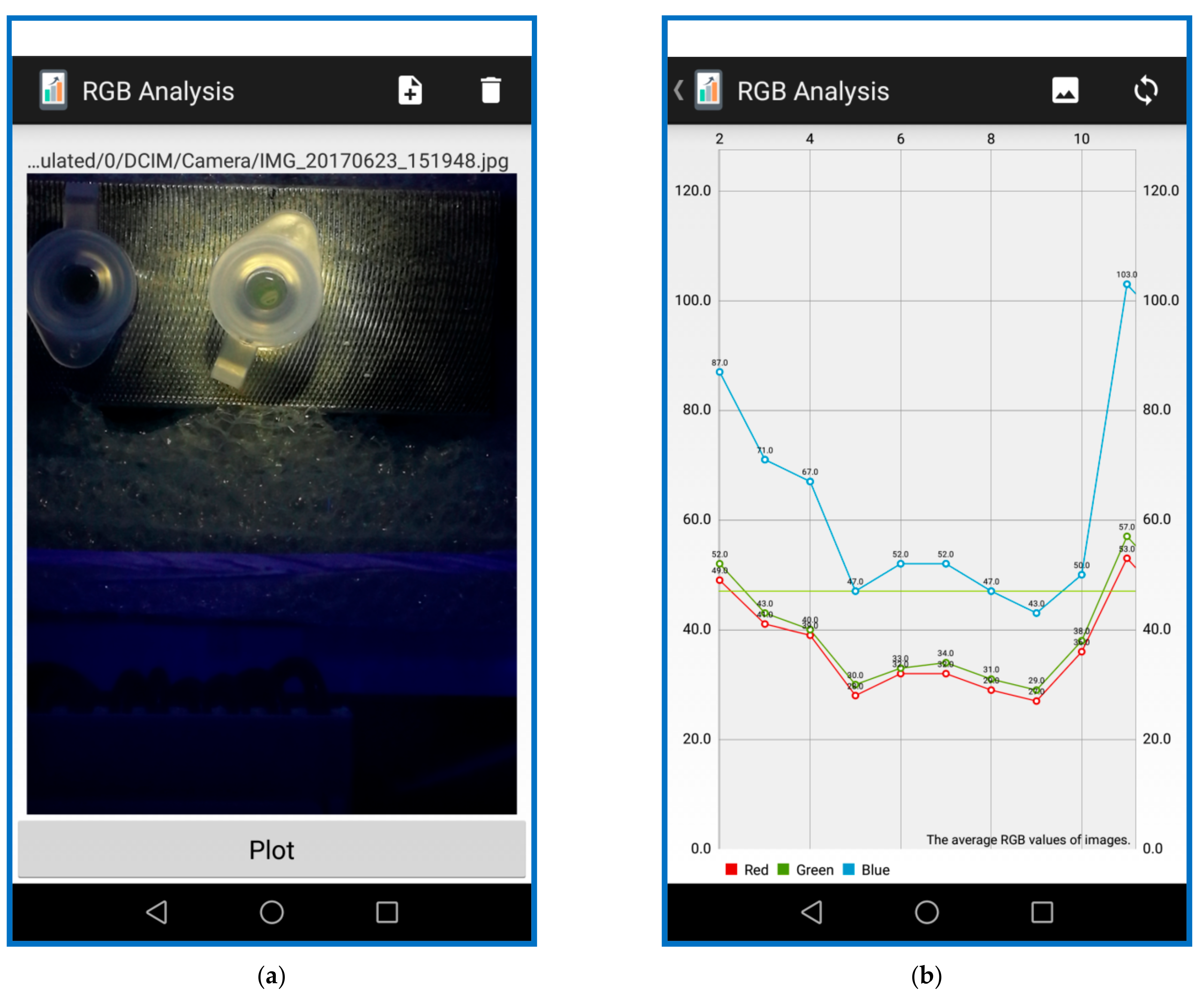
The image-processing algorithms are executed using OpenCV (open-source computer vision). The OpenCV library is a common library used in image-processing applications. Fluorescence images of the DNA mixture are captured by the smartphone in JPEG format (shown in
Figure 3a). The RGB intensity components for each pixel are stored as an integer ranging from 0 to 255 (shown in
Figure 3b). Since the fluorescence emits from the DNA product, the green fluorescence (about 515 nm) is stimulated and the average values of all the pixel intensities are calculated. Due to the weak fluorescence of the unbound dye, the average intensity measured at the beginning is used as a background intensity that is subtracted from the measured output intensity of all the other results. The image processing performed by the app reduces each data group to a single intensity value, representing the average fluorescence intensity within the region of interest, minus the average fluorescence intensity at the beginning.
2.4. DNA Sample Preparation and PCR Conditions
The protocols for the extraction and amplification of the genetic material, the primers used, and other parameters related to the amplification have been described in detail in our previous work [
2]. We will add some brief descriptions of these issues in our manuscript.
The DHG samples are frozen, ground and stored at −80 °C. Afterward, 1 g of DHG powder is suspended in the digestion buffer and subjected to a water bath until completely dissolved. Then, protease K is added for sample digestion prior to centrifugation. The supernatant is subjected to genomic DNA extraction using a QIAquick® nucleotide removal kit (QIAGEN, Hilden, Germany) and is used as a DNA template.
DNA amplification is performed by LAMP, which targets a fragment of the donkey-skin gene. The sample is injected into the chamber using a micropipette. On the LAMP detection device and commercial PCR machine (MJ Mini™ 48-Well Personal Thermal Cycler, Bio-Rad, Hercules, CA, USA), the DNA mixture, with a total volume of 25 μL, contains 12.5 μL of 2 × reaction mix (DNA Amplification Kit, Eiken Chemical Co. Ltd., Tokyo, Japan) (2.8 mM of each deoxyribonucleotide triphosphate (dNTP), 0.2% of Tween 20, 40 mM of Tris-HCl (pH 8.8), 20 mM of KCl, 1.6 M of Betaine, 16 mM of MgSO4, 20 mM of (NH4)2SO4), 1 μL of 40 μM FIP/BIP primers, 0.5 μL of 10 μM F3/B3 primers, 1 μL of Bst DNA polymerase (8000 U/μL stock), 2 μL of template DNA (20 ng/μL), and 6.5 μL of distilled water. At this point, 1 μL of the fluorescent detection reagent (Loopamp® fluorescent detection reagent, Eiken Chemical Co. Ltd., Japan) is needed when the LAMP process is carried out in our device.
The LAMP primers (FIP/BIP and F3/B3 primers) are manually designed using the PrimerExplorer V4 software, based on the consensus sequence of 12S ribosomal DNA (rDNA) obtained from GenBank. The primers are as follows—forward outer primer (F3), 5′-TGGAGAGAAATGGGCTACA-3′; backward outer primer (B3), 5′-CATGGTTTTGTGTAATATTGTGA-3′; forward inner primer (FIP), 5′-TCCCATGGGCTACACCTTGA-AAACCCTAAACAAGGTACCAA-3′; backward inner primer (BIP), 5′-ACTCTAAGAACAAGAACTCAACCC-AATCCTCCTTCGGTCTCT-3′.
A conventional thermal cycler executes the protocol program for LAMP amplification. The heating conditions are as follows: 3 min at 95 °C for the polymerase activation and the DNA denaturation, 60 min at 62 °C for the DNA target annealing, and 30 s at 80 °C for the final extension. At this point, 2 μL of the distilled water replaces the template DNA as the negative control sample.
The DNA product is pipetted out of the reaction tube and mixed with bromophenol blue dye after completing the LAMP process. Then, 10 μL of the DNA product is loaded onto 2% of agarose gel (certified molecular biology agarose, Bio-Rad), added into 10× Tris-acetate-EDTA (TAE) buffer and 10× Tris-boric-EDTA (TBE) solution, and analyzed by a gel electrophoresis system (Mini-Sub Cell GT System, Bio-Rad). Once the electrophoresis is finished, the gel is stained with ethidium bromide solution for 15 min, and then viewed using a UV transilluminator.
2.5. Operation Procedure
For real-time detection in the portable device, the 25 μL DNA mixture is pipetted into the reaction tube. A layer of mineral oil is utilized on top of the DNA samples to prevent water condensation and air bubbles. The reaction tubes are positioned in the aluminum block and the process is ready to begin. When the tube is heated and the mixture temperature reaches the correct reaction temperature, the amplification is carried out for 60 min at 62 °C. The smartphone is also initiated to record the real-time fluorescence emission from the tubes. The phone camera acquires an image once every 3 min, and the image is analyzed by the homemade app.
3. Results and Discussion
The LAMP experiments on DNA samples extracted from Asini Corii Colla were carried out, and real-time detection by a smartphone was also implemented in the portable device. In the following sections, we show the transfer of heat in a LAMP solution inside a tube that is exposed to one isothermal heating zone. The thermal control concepts were demonstrated in terms of the temperature profiles. The influences of the operational parameters on the DNA analysis processes inside the chamber were also examined. The sensitivity of the device was presented. The chamber was exposed to one heating source during the LAMP processes in order to reduce the device volume and save on system cost. Finally, the results were expressed to ensure the applications of the real-time detection of Asini Corii Colla in the portable device.
3.1. Thermal Control Concepts
From the preliminary studies on the LAMP reactor, some researchers have utilized the electricity-free heating method to control the mixture temperature for the simplicity of the system integration. In our study, the cartridge heater, inserted into an aluminum block and powered by a programmable DC voltage supply, was used as a single heating source. The rising time and the residence time, respectively, were easily regulated by the arrangement of heating power units with active thermal control.
A DC power unit was used to supply the power requirement when the system is working. The power usage during the LAMP process includes the heating of the heater, the sensing of all the sensors, the operation of the microprocessor and the LCD display. The battery recharger is constructed into the function of the PCB, and the batteries can be recharged during the LAMP process. In the current device, the maximum power supply for the cartridge heater is 14 W, and the maximum electric current needed for supplying full power is 1.4 A. The 18,650 cell, with a normal voltage of 3.7 V and maximum voltage of 4.2 V, was exploited and gave between 1.8 Ah and 3.5 Ah (ampere-hour). Two different sets of 18,650 batteries were measured during the LAMP process to ensure the rising time was shortened and the duration was long enough. Two or three serial-connected 18,650 batteries were supported. The rising time to reach a stable temperature of 65 °C inside the reaction tube is about 767 and 211 s for two and three serial-connected 18,650 batteries, respectively. Therefore, three serial-connected 18,650 batteries were used in the portable device.
For an efficient LAMP process, the temperature uniformity of the DNA sample mixture is one of the major issues and influences the amplification efficiency during the DNA target annealing. The repeatability and the stability of the LAMP device were investigated before the LAMP processes. The 25 μL DNA mixture was pipetted into the reaction tube. The temperature profiles measured by the thermocouple inside the reaction tube at 5 different times were presented (not shown in the manuscript). A computer recorded the real-time temperature profiles through the NI 9211 interface. A ±0.5 °C temperature tolerance in the thermal control scheme was allowed, to ensure a stable temperature of 62 °C inside the reaction tube. The experimental temperature curves were similar; the standard deviations of the temperatures at 5 sets of measurements were within 0.314 °C. The repeatability of this LAMP device was then verified.
The stability of the portable device was also examined. The measuring thermal profiles inside the tubes for 60 min, taken 5 times, were analyzed. Little difference among the temperature profiles was found. The standard deviations of the temperature profiles after the sample temperatures reached the requested value at 5 sets of measurements and were within 1.091 °C. Then, the stability of the device could be confirmed.
3.2. DNA Amplification in the Chamber
The cartridge heater inside the reaction aluminum chamber heated the sample directly, and the stability and repeatability of the thermal characteristics inside the portable device were investigated. The performance of LAMP amplification of the portable device was then compared to the conventional method. The detection of DNA amplification was accomplished using agarose gel, as well as by real-time monitoring of fluorescence.
The tube was loaded with LAMP reagents, accompanied by the template DNA sample of
Asini Corii Colla, at a concentration of 10
−1 ng/μL. The results of gel electrophoresis of the LAMP products are presented in
Figure 4a,b. The lane (Mk) in
Figure 4a indicates the DNA ladder. From the electrophoresis analyses of lane (L) (the portable device) and lane (N) (a thermocycling machine) in
Figure 4a, the LAMP products were produced with a ladder-like pattern on the gel (from 100 bp to 500 bp) that was similar to that of the reference DNA and the extracted DNAs from the DHG samples [
36], and the DNA mixtures were successfully amplified for positive control samples. The non-specific products were not found. The results obtained in our work are almost similar to the previous study [
2]. It was noticed that the fluorescence intensity of the DNA product at lane (L) was smaller than that at lane (N). This might cause the reaction to be inefficient, due to the insufficiently precise temperature among the working regions. However, the result is still obvious enough. A mixture for a negative control was injected into the tube and the result is also presented in
Figure 4a (lane (NC)). There was no band expressed in the negative sample.
Due to the spatial separation between the sensor temperature and the DNA temperature in the tube, the temperature measured using thermocouples was utilized to calibrate the setting temperature for feedback control. The results of electrophoresis of the LAMP products are expressed in
Figure 4b after temperature calibration. The lane (Mk), lane (N), lane (L) and lane (NC) in
Figure 4b, respectively, indicate a DNA ladder, a positive control in a thermocycling machine, a positive control in our device and a negative control. The results included agarose gel electrophoresis of the LAMP products, displaying the typical ladder-like patterns. The fluorescence intensities of the DNA product at lane (L) and that of the product at lane (N) were similar. Non-specific products were not found at lane (NC).
To generate the amplification signal in the form of turbidity in
Figure 4c, it was found that the turbidity in the sample tube under the UV light was shown for the positive sample (at the right side of
Figure 4c). As the LAMP reactions continue, pyrophosphate ions (P
2O
74−) are released from the dNTP reagents and these react with magnesium ions (Mg
2+) in the DNA mixture to produce a white, insoluble magnesium pyrophosphate precipitate (Mg
2P
2O
7). This product resulted in progressively increasing turbidity of the reaction solution [
8] Furthermore, there was no turbidity in the negative sample (at the left side of
Figure 4c).
3.3. Real-Time DNA Detection in the Chamber
The main objective of the study is to present the feasibility of real-time detection of the DNA extracted from
Asini Corii Colla in tubes using a smartphone. For detection, 1 μL of fluorescent detection reagent was added to the reaction tube with the same ratio of DNA mixtures as used in
Figure 5. This reagent allows the amplification reaction to be detected, using ultraviolet (UV) light. Calcein included in the detection reagent initially binds to manganese ion (Mn
2+) and thus remains for quenching. When the LAMP reaction occurs, the Mn
2+ is departed from calcein by the formation of Mg
2P
2O
7, which results in the emission of fluorescence. The fluorescence signals from the reaction tube were monitored in real time by utilizing the smartphone-based imaging system. The signal profiles displayed positive detection curves in 60 min.
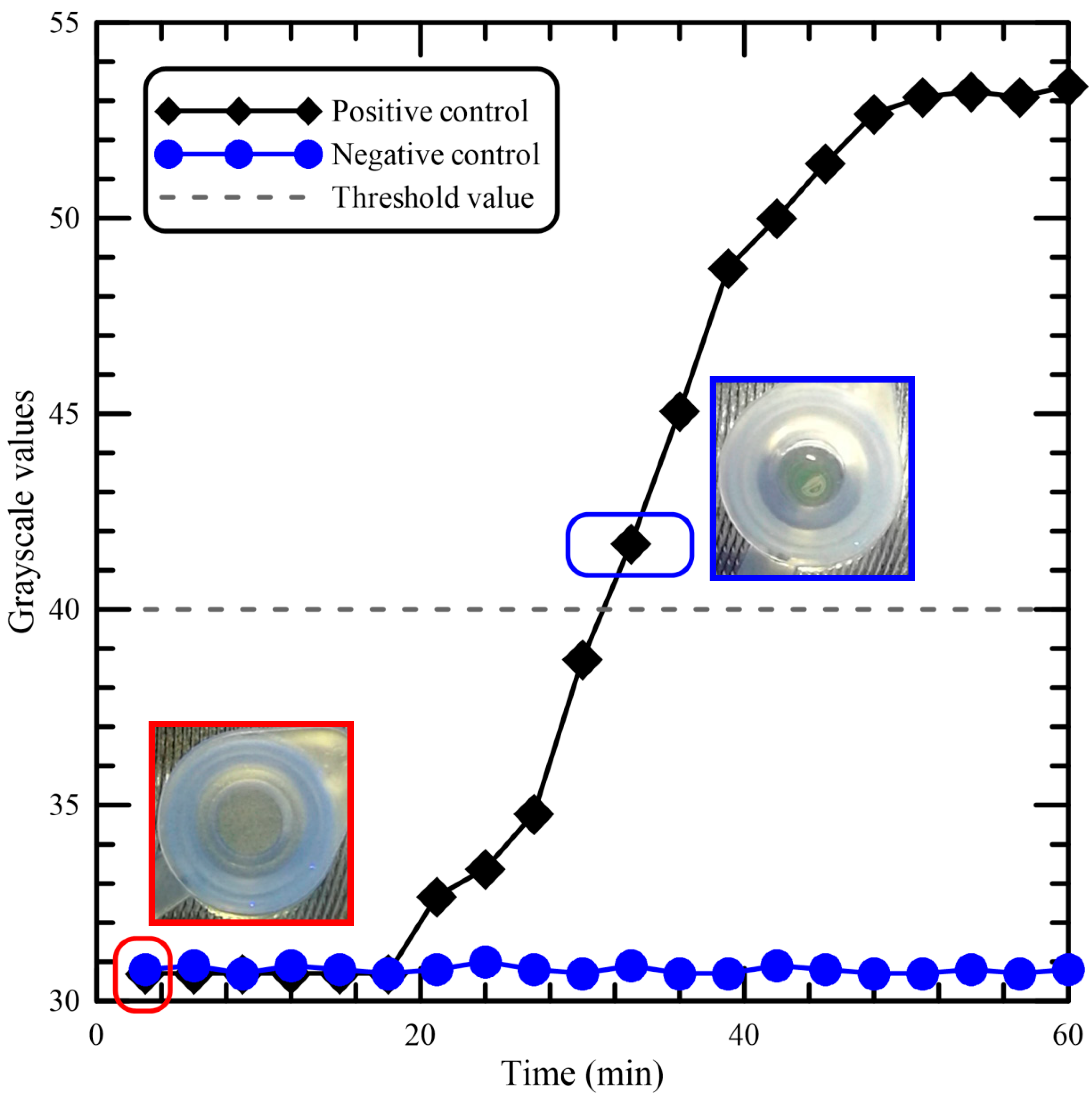
Figure 5 shows the results for the real-time kinetics of the LAMP reaction, with or without DNA samples, at 62 °C by monitoring fluorescence intensities from the tube. The graph demonstrates the characteristic sigmoidal shape of a real-time amplified reaction, and there is a clear difference between the amplification and the negative control. The result using the negative control is presented, and the grayscale values get fixed at around 31 for the negative control having no DNA template. For the positive control, the results indicate that the time required for initiation of amplification was about 18 min. The picture marked by a red rectangle has been taken at the time when the LAMP process begins, and the grayscale value is about 30.7. The picture marked by a blue rectangle shows that the fluorescence light was visible from the top of the tube. There was no water condensation on the tube lid. The influence of sample condensation during amplification on both amplification efficiency and fluorescence readout for the developed device was negligible in our device. The reduction of fluorescence readouts from the sample condensation has been described in the previous work [
31]. For the determination of the detection limit of the portable device, the minimum grayscale value that could be detected by the naked eye was used as the threshold value. The threshold grayscale value, set as the fluorescence light can be seen from the tube, is equal to 40. The assay required at least 32 min for detection of
Asini Corii Colla from the beginning of the LAMP process.
To evaluate the performance of the portable device for the quantification of DNA mixtures, several serially diluted DNA samples were utilized. The LAMP assays using fluorescence detection reagent were compared with regard to the detection of 10-fold serially diluted DNA. The amplification curves for DNA samples are expressed in
Figure 6 and were analyzed for the sensitivity of the device. The times to reach the threshold value of 40 at the concentrations of 10
−1, 10
−2, 10
−3, and 10
−4 ng/μL were about 30, 37, 43, and 46 min, respectively. At the concentration of 10
−5 ng/μL, the fluorescence signals were almost similar to the signals emitted from the negative sample. In terms of the analytical sensitivity of LAMP in 60 min, a lower limit of detection of the concentration of 10
−4 ng/μL was achieved.
As illustrated in
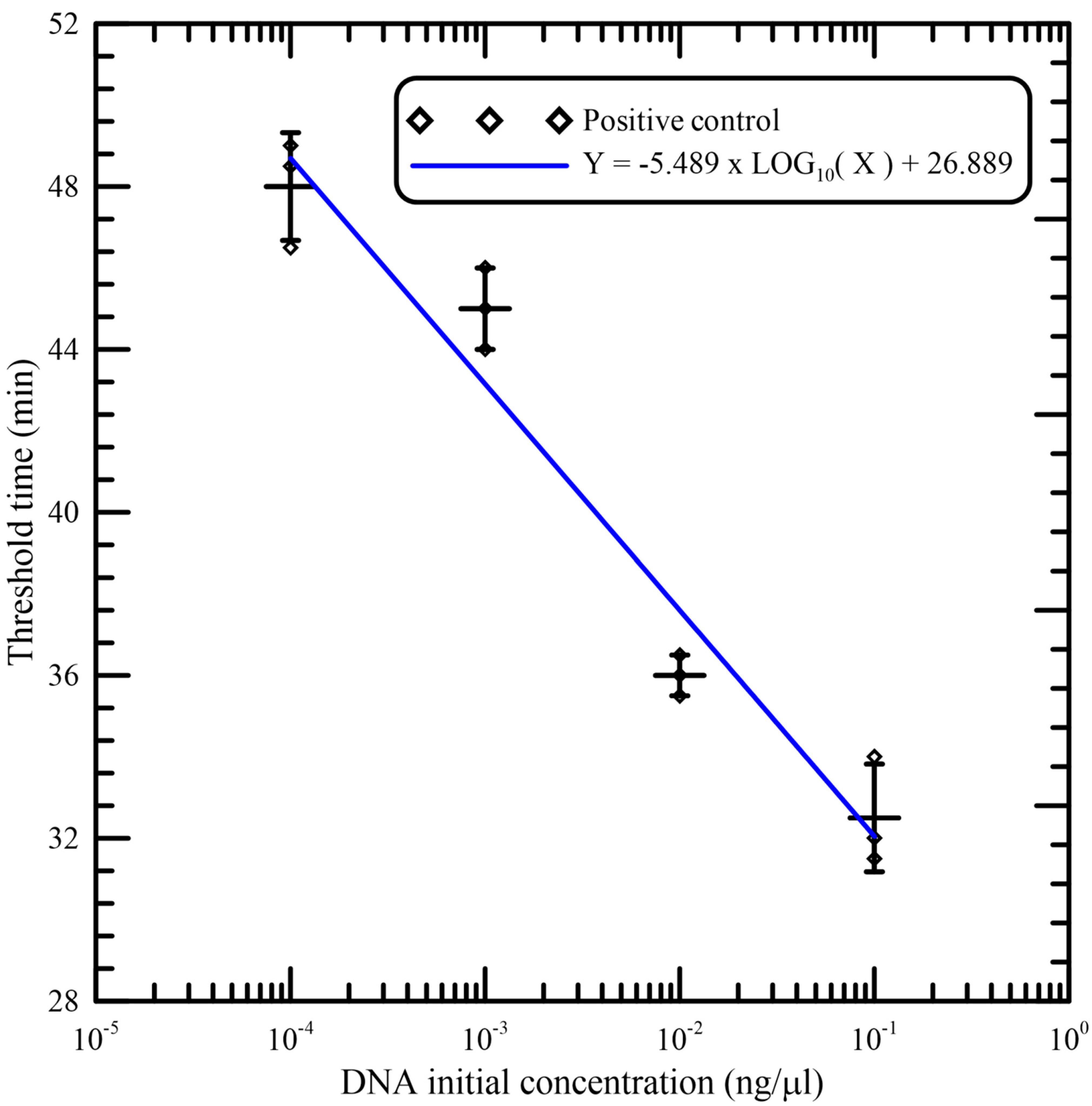
Figure 7, good linearity was observed between the threshold time and logarithm of the initial concentration of DNA samples per reaction. The data (shown in
Table 1) from independent triplicates were able to generate confident linear regression (goodness-of-fit measurement, R
2 = 0.959) for quantitative detection of a template with Y = −5.489 × LOG
10(X) + 26.889, where Y is the threshold time and X is the DNA initial concentration. The standard deviations (SD) and the coefficients of variation (CV) of independent triplicates are also shown in
Table 1. This verifies that amplification was reliable and that the portable device could be utilized for quantification.
