
The Design and Development of a Foldable Wheelchair Stretcher


Abstract
1. Introduction
2. Literature Review
- Simple stretcher: A basic type of stretcher carried by two or more people with no other feature or function besides moving a patient [12].
- Folding stretcher: A foldable stretcher consisting of two hinged bars, two poles and a cloth-like platform for improved portability and storage reduction [13].
- Litter (Rescue basket): A stretcher that firmly secures the patient while being transported through unsafe or uneven terrain (e.g., on a mountain) [14].
- Wheeled stretcher: A one-man operated stretcher where the medical person pushes and manoeuvres the stretcher with the help of the wheels [15].
2.1. Wheels
2.2. Steel
2.3. Aluminium
2.4. Wood
3. Materials and Methods
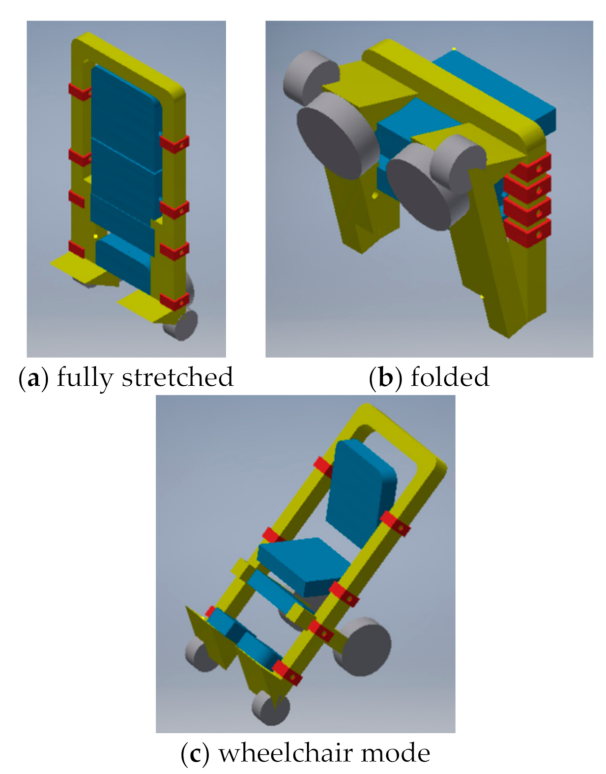
3.1. Stretcher Concept
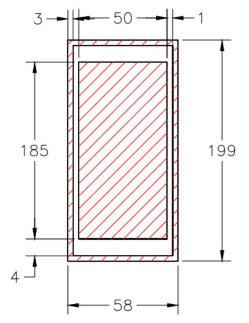
3.2. Stretcher Dimensions
3.3. Component Selection: Wheels
- 0: Unacceptable fulfilment of criteria.
- 1: Extremely poor fulfilment of criteria.
- 2: Very poor fulfilment of criteria.
- 3: Poor fulfilment of criteria.
- 4: Somewhat poor fulfilment of criteria.
- 5: Satisfactory fulfilment of criteria.
- 6: Somewhat good fulfilment of criteria.
- 7: Good fulfilment of criteria.
- 8: Very good fulfilment of criteria.
- 9: Extremely good fulfilment of criteria.
- 10: Exceptional fulfilment of criteria.
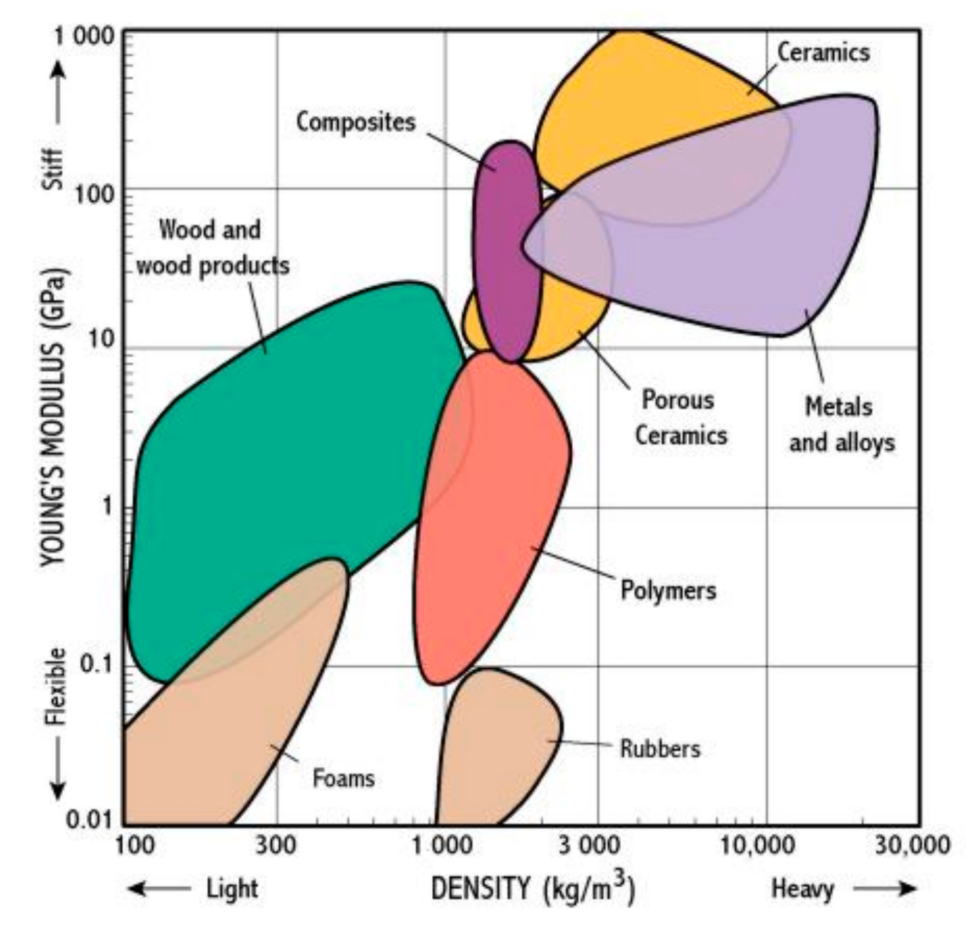
3.4. Material Selection: Frame
3.5. Material Selection: Platform
3.6. Simulation and Analysis
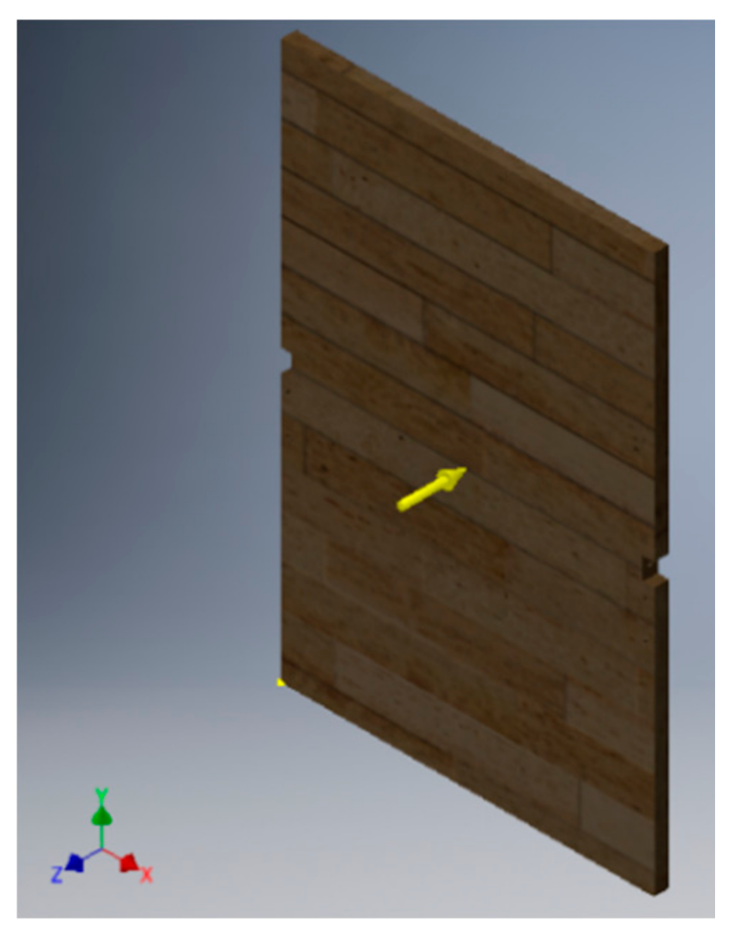
3.6.1. Platform Simulation
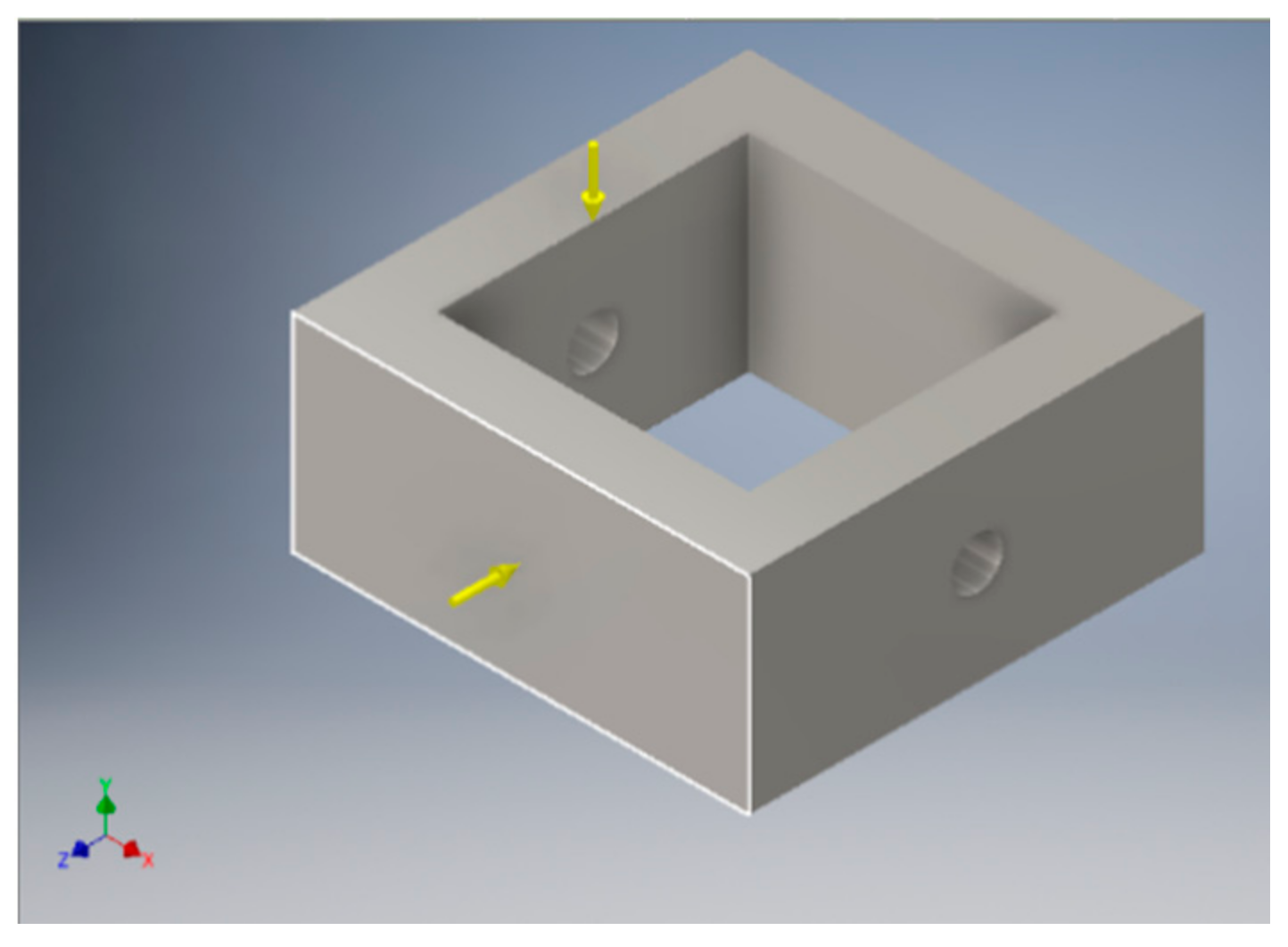
3.6.2. Slider Simulation
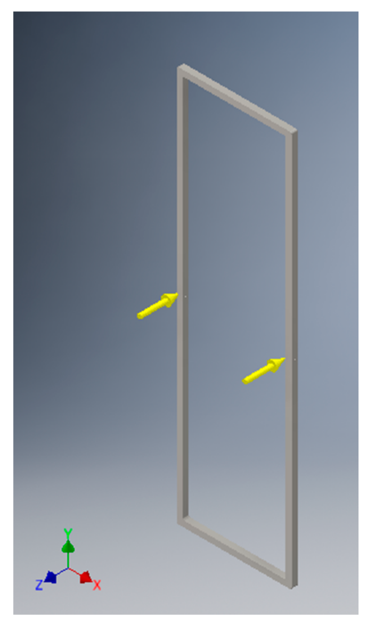
3.6.3. Frame Simulation
3.6.4. Bending Analysis
3.6.5. Maximum Load Analysis
3.7. Usability Test Plan
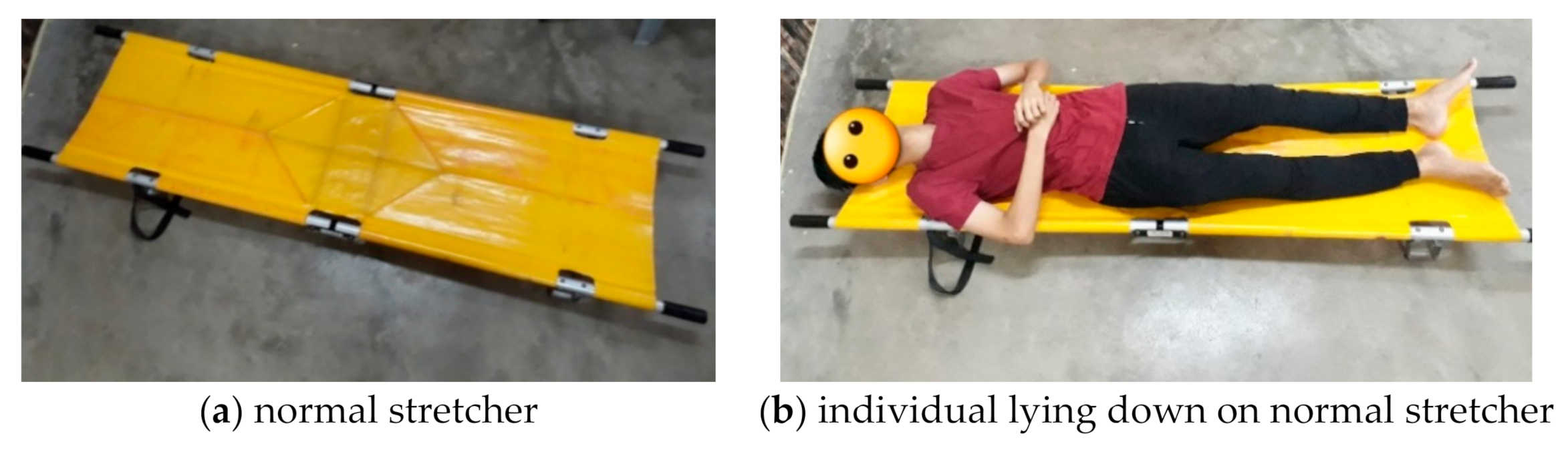
3.7.1. Test 1: Normal Stretcher Use
- Six (6) people are assigned to act on behalf of the medical person, while one (1) person is assigned to act on behalf of the patient. Since they are not actual medical workers and patients, they will be known throughout the experiment as transporting users (the medical workers) and the transported user (the patient). The users are indicated as A, B, C, D, E and F.
- Two transporting users are to form a group with one of them carrying the front handle and the other carrying the back handle of the stretcher. The groupings are shown in Table 10.
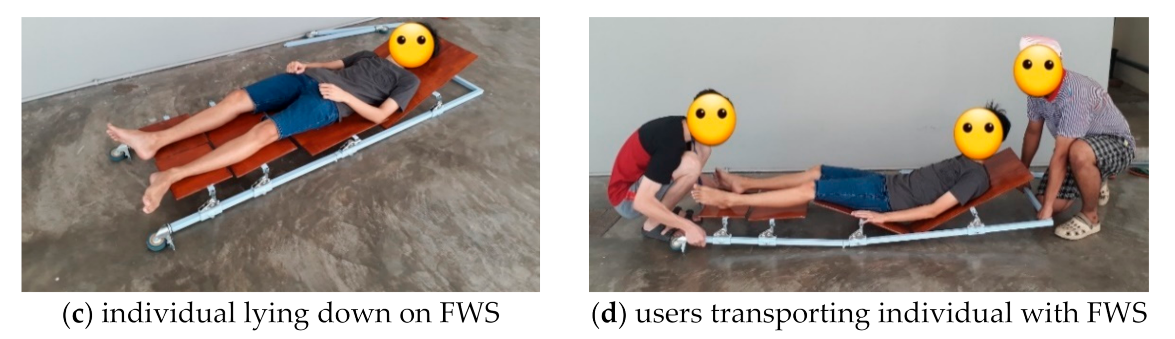
- The normal stretcher is placed on the floor, and the transported user lies down on the stretcher. The group formed in step 2 has to standby beside the transported user.
- When the timer starts, both members of the transporting user group are to lift the stretcher up at their assigned positions.
- Upon lifting the stretcher, both transporting users are to travel through a distance of 10 m at the fastest speed possible without dropping the patient.
- The stretcher is placed down and the timer stopped. The total duration is recorded.
- If at any point in steps 4, 5 and 6, an error occurs, the test is to be repeated from steps 3 to 6.
- Steps 3 to 7 are repeated with groups 2 to 30.
- Steps 3 to 8 are repeated using the FWS.
3.7.2. Test 2: Folding Stretcher
- The normal stretcher is placed on the floor in a fully stretched mode.
- When the timer starts, person A commences folding the stretcher.
- The timer stops when the stretcher is completely folded. The total duration is then recorded (See Table 11).
- When the timer starts again, person A begins to unfold the stretcher.
- The timer is stopped when the stretcher is fully stretched. The total duration is recorded again.
- Steps 1 to 5 are repeated for person B, C, D, E and F.
- Steps 1 to 6 are repeated 5 times.
- Steps 1 to 7 are repeated using the FWS.
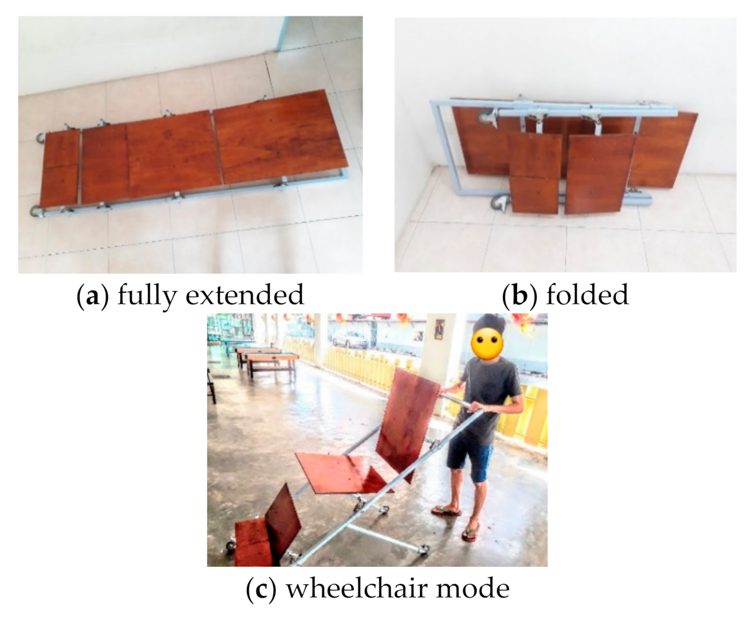
3.7.3. Test 3: Alternate Function
- The stretcher is folded into a wheelchair. The platform of the seat is adjusted to be parallel to the ground (45° to the frame).
- Person A sits on the wheelchair and slowly adjusts the angle of the platform just before he/she begins to slide off the seat. The increment of the angle is recorded (See Table 12 for the data collection method).
- Steps 1 and 2 are repeated for persons B, C, D, E and F.
- The platform of the seat is adjusted back to be parallel to the ground and the transported user sits on it before the subsequent tasks are carried out.
- All transporting members then try to complete the following tasks:
- (a)
- Push the transported user on the wheelchair to move a distance of 10 m
- (b)
- Zero radius left turn
- (c)
- Zero radius right turn
- If the task is able to be completed, a checkmark is granted (✓). If not, a cross mark is given (✕) (See Table 13 for the data collection method).
3.8. Analysis Planning
3.8.1. Analysis Planning for Test 1 and 2
3.8.2. Analyses Planning for Test 3
4. Results and Discussion
4.1. Final Product
4.2. Results for Test 1
4.3. Results for Test 2
4.4. Results for Test 3
4.5. Key Findings and Discussion
4.5.1. The Weight of the FWS Very Much Affects Its Performance
4.5.2. Simple Designs Are More User Friendly
4.5.3. The Design of the Prototype Should Be Flexible
4.6. Cost Analysis
5. Conclusions
5.1. Limitations of Study
5.2. Directions for Future Research
Author Contributions
Funding
Institutional Review Board Statement
Informed Consent Statement
Data Availability Statement
Acknowledgments
Conflicts of Interest
References
- Hoare, S.; Kelly, M.P.; Prothero, L.; Barclay, S. Ambulance staff and end-of-life hospital admissions: A qualitative interview study. Palliat. Med. 2018, 32, 1465–1473. [Google Scholar] [CrossRef] [PubMed]
- Varghese, T. Innovation: The simple stretchers. Med. J. Armed Forces India 2003, 59, 42–43. [Google Scholar] [CrossRef]
- Armstrong, D.P.; Ferron, R.; Taylor, C.; McLeod, B.; Fletcher, S.; MacPhee, R.S.; Fischer, S.L. Implementing powered stretcher and load systems was a cost effective intervention to reduce the incidence rates of stretcher related injuries in a paramedic service. Appl. Ergon. 2017, 62, 34–42. [Google Scholar] [CrossRef] [PubMed]
- Ham, S.H.; Song, W.S.; Yoon, M.O. A study on the problems and improvement solutions for the ambulance stretcher. Fire Sci. Eng. 2014, 28, 72–79. [Google Scholar] [CrossRef][Green Version]
- Prairie, J.; Plamondon, A.; Larouche, D.; Hegg-Deloye, S.; Corbeil, P. Paramedics’ working strategies while loading a stretcher into an ambulance. Appl. Ergon. 2017, 65, 112–122. [Google Scholar] [CrossRef]
- Studnek, J.R.; MacCrawford, J.; Fernandez, A.R. Evaluation of occupational injuries in an urban emergency medical services system before and after implementation of electrically powered stretchers. Appl. Ergon. 2012, 43, 198–202. [Google Scholar] [CrossRef]
- Wang, H.E.; Weaver, M.D.; Abo, B.N.; Kaliappan, R.; Fairbanks, R.J. Ambulance stretcher adverse events. Qual. Saf. Health Care 2009, 18, 213–216. [Google Scholar] [CrossRef]
- Dimentmen, N. Compact Foldable Stretcher. U.S. Patent US20050210589A1, 16 May 2006. [Google Scholar]
- Pezzetti, H. Stretcher. U.S. Patent US1275734A, 13 August 1918. [Google Scholar]
- Hughes, R.C. Stretcher. U.S. Patent US2675564A, 20 April 1954. [Google Scholar]
- Lim, S.H.; Ng, P.K. Synthesisation of design features for multifunctional stretcher concepts. J. Med. Eng. Technol. 2021, 45, 145–157. [Google Scholar] [CrossRef]
- Hulldin, M.; Kängström, J.; Hagiwara, M.A.; Claesson, A. Perceived exertion using two different ems stretcher systems. Am. J. Emerg. Med. 2018, 36, 1040–1044. [Google Scholar] [CrossRef]
- Vignesh, V.; Prakash, R.; Stephen, S.M.; Kumar, S.A. Design and development of two in one foldable stretcher cum wheel chair. Int. Res. J. Eng. Technol. 2017, 4, 2739–2745. [Google Scholar]
- Frye, S.Z. Helicopter Rescue Basket. U.S. Patent US4564161, 14 January 1986. [Google Scholar]
- Mapari, V.P.; Mashakhetri, A.S.; Kumar, L.; Bag, S.S.; Hande, A.S. A review on design and fabrication of multiutility wheel chair. Int. J. Innov. Res. Sci. Technol. 2017, 3, 178–181. [Google Scholar]
- Katoch, S. Introduction of modern stretchers in armed forces for improving casualty evacuation in field with special reference to casualty evacuation in mountains. Med. J. Armed Forces India 2005, 61, 157–162. [Google Scholar] [CrossRef][Green Version]
- AZ Medical. Plastic Scoop Stretcher. 2020. Available online: https://emslifes.com/product/scoop-stretcher/ (accessed on 3 November 2020).
- Krell, J.M.; McCoy, M.S.; Sparto, P.J.; Fisher, G.L.; Stoy, W.A.; Hostler, D.P. Comparison of the ferno scoop stretcher with the long backboard for spinal immobilization. Prehospital Emerg. Care 2009, 10, 46–51. [Google Scholar] [CrossRef]
- Ridden, P. Scoop Stretcher Can Transform to a Lightweight Stretcehr in Seconds. 2019. Available online: https://newatlas.com/multi-scoop-pro-wheelchair-stretcher/59835/ (accessed on 3 November 2020).
- Del Rossi, G.; Rechtine, G.R.; Conrad, B.P.; Horodyski, M. Are scoop stretchers suitable for use on spine-injured patients? Am. J. Emerg. Med. 2009, 28, 751–756. [Google Scholar] [CrossRef]
- Bag, S.S.; Lohe, P.D.; Hajare, H.K.; Madne, A.N.; Hande, A.S. Design and fabrication of multiutility wheelchair. Int. J. Innov. Res. Sci. Technol. 2017, 3, 182–188. [Google Scholar]
- Waghmare, S.N.; Sawant, N.; Dhumal, S.; Patil, N.K.P.; Dambe, P.R. Design and analysis of compact stretcher with rubber shock absorbers. Int. J. Eng. Res. Sci. Technol. 2015, 4, 130–134. [Google Scholar]
- Lothschuetz, F.X. Stretcher. U.S. Patent US3343180A, 26 September 1967. [Google Scholar]
- Panton, G.S. Thermoplastic Spine Board with Ergonomic Features. U.S. Patent US7303705B2, 4 December 2007. [Google Scholar]
- Bauer, R.; Leung, W.; Barfoot, T. Experimental and simulation results of wheel-soil interaction for planetary rovers. In Proceedings of the IEEE/RSJ International Conference on Intelligent Robots and Systems, Edmonton, AB, Canada, 2–6 August 2005. [Google Scholar]
- Ding, L.; Gao, H.; Deng, Z.; Nagatani, K.; Yoshida, K. Experimental study and analysis on planetary exploration rovers. Terramechanics 2011, 48, 27–45. [Google Scholar] [CrossRef]
- Sutoh, M.; Yusa, J.; Ito, T.; Nagatani, K.; Yoshida, K. Traveling performance evaluation of planetary rovers on loose soil. Field Robot. 2012, 29, 648–662. [Google Scholar] [CrossRef]
- Le, M.; Jun, J.; Kim, J.; Lee, J. Non-destructive testing of train wheels using differential-type integrated hall sensor matrixes embedded in train rail. NDT E Int. 2013, 55, 28–35. [Google Scholar] [CrossRef]
- Zheng, B.; Shu, G.; Wang, J.; Gu, Y.; Jiang, Q. Predictions of material properties in cold-rolled austenitic stainless steel tubular sections. J. Constr. Steel Res. 2019, 164, 105–131. [Google Scholar] [CrossRef]
- Krishnan, P.K.; Christy, J.V.; Arunachalam, R.; Mourad, A.H.I.; Muraliraja, R.; Al-Maharbi, M.; Murali, V.; Chandra, M.M. Production of aluminum alloy based metal matrix composites. J. Alloy. Compd. 2019, 784, 1047–1061. [Google Scholar] [CrossRef]
- Cui, J.; Roven, H.J. Recycling of automotive aluminum. Trans. Nonferrous Met. Soc. China 2010, 20, 2057–2063. [Google Scholar] [CrossRef]
- Yano, H.; Hirose, A.; Inaba, S. High-strength wood-based materials. J. Mater. Sci. Lett. 1997, 16, 1906–1909. [Google Scholar] [CrossRef]
- Wei, J.; Rao, F.; Zhang, Y.; Yu, W.; Hse, C.; Shupe, T. Laminating wood fiber mats into a densified material with high performance. Mater. Lett. 2019, 253, 358–361. [Google Scholar] [CrossRef]
- Li, Y.F.; Liu, Y.X.; Wang, X.M.; Wu, Q.L.; Yu, H.P.; Li, J. Wood–polymer composites prepared by the in situ polymerization of monomers within wood. J. Appl. Polym. Sci. 2011, 119, 3207–3216. [Google Scholar] [CrossRef]
- Fryar, C.D.; Gu, Q.; Ogden, C.L.; Flegal, K.M. Anthropometric Reference Data for Children and Adults: United States, 2011–2014; National Center for Health Statistics, Vital and Health Statistics: Washington, DC, USA, 2016; Volume 3, pp. 1–38. [Google Scholar]
- Lim, T.O.; Ding, L.M.; Zaki, M.; Suleiman, A.B.; Fatimah, S.; Siti, S.; Tahir, A.; Maimunah, A.H. Distribution of body weight, height and body mass index in a national sample of malaysian adults. Med. J. Malays. 2000, 55, 108–128. [Google Scholar]
- Dore. Industrial Caster Series. 2019. Available online: https://www.dorecaster.com/Products/Industrial-Caster-Series (accessed on 19 August 2019).
- Tente. Diversity with a System: Our Castors. 2019. Available online: https://www.tente.com/en-my/product-families (accessed on 1 August 2019).
- Ugural, A.C.; Fenster, S.K. Advanced Strength and Applied Elasticity, 6th ed.; Pearson: London, UK, 2019. [Google Scholar]
- Shercliff, H.; Lovatt, A.; Withers, P. The Physical Basis of Selection Charts: A Teacher’s Guide to Teaching Material Properties. 2021. Available online: http://www-materials.eng.cam.ac.uk/mpsite/physics/str-tough_article/default.html (accessed on 16 January 2021).
- So, T.-Y.; Farrington, E.; Absher, R.K. Evaluation of the accuracy of different methods used to estimate weights in the pediatric population. Pediatrics 2009, 123, 1045–1051. [Google Scholar] [CrossRef]
- Indian Healthcare Company. Four Fold Stretcher. 2017. Available online: http://www.indianhealthcarecompany.in/four-fold-stretcher.htm (accessed on 19 February 2020).
- Caligiuri, M.P.; Tripp, R.M. A portable hand-held device for quantifying and standardizing tremor assessment. J. Med. Eng. Technol. 2004, 28, 254–262. [Google Scholar] [CrossRef]
- Gold, R.G. Evaluation of portable electrocardiographs. J. Med. Eng. Technol. 1977, 1, 324–327. [Google Scholar] [CrossRef]
- Manson, G.; Read, J. A low cost portable enuresis alarm. J. Med. Eng. Technol. 1979, 3, 83–84. [Google Scholar] [CrossRef]
- Sintotskiy, G.; Hinrichs, H. In-ear-EEG—A portable platform for home monitoring. J. Med. Eng. Technol. 2020, 44, 26–37. [Google Scholar] [CrossRef] [PubMed]
- Tasalloti, H.; Eskelinen, H.; Kah, P.; Martikainen, J. An integrated DFMA–PDM model for the design and analysis of challenging similar and dissimilar welds. Mater. Des. 2016, 89, 421–431. [Google Scholar] [CrossRef]
- Volotinen, J.; Lohtander, M. The re-design of the ventilation unit with DFMA aspects: Case study in finnish industry. Procedia Manuf. 2018, 25, 557–564. [Google Scholar] [CrossRef]
- Wu, Y.; Zhou, F.; Kong, J. Innovative design approach for product design based on TRIZ, AD, fuzzy and grey relational analysis. Comput. Ind. Eng. 2020, 140, 106276. [Google Scholar] [CrossRef]


| Stretchers | Sources | Features | Pros | Cons |
|---|---|---|---|---|
| Four-fold stretcher | [16] | able to fold to four (4) segments | stretcher size is reduced once folded | none |
| platform is soft | compressible or foldable for size reduction purpose | the user could still sink into the platform | ||
| Scoop stretcher | [17,18,19,20] | splits vertically | omits the need of carrying and placing the user onto the stretcher by scooping him/her up | none |
| platform is hard | reduces possibility of undesirable movement | non-foldable | ||
| Multiutility wheelchair | [15,21] | transforms from stretcher to wheelchair and vice versa | user has the choice of sitting instead of lying down | size reduction not possible |
| only one person needed to push wheelchair | ||||
| Rubber shock absorbers | [22] | reduces vibrations and shock | avoids damages to internal organs | only needed when user is critically injured |
| function only applies with soft platforms | ||||
| Compact foldable stretcher | [8] | able to be folded into a bag | portable | complicated process of assembly |
| Foldable handle | [9] | foldable handle | a small amount of space is saved | small space-saving benefit seems inconspicuous with heavy manufacturing effort |
| Portable stretcher | [10] | able to be folded into a luggage | portable | challenging to manufacture due to its complex parts |
| Rigid head and neck support | [23] | supports the neck and head | good for users with head and neck injuries | only needed when users have head or neck injuries |
| supporting mechanisms reduce flexibility | ||||
| Thermoplastic spine board | [24] | lightweight thermoplastic | portable | costly |
| Brand | Model | Dimensions (L × W × H) cm | Weight (kg) |
|---|---|---|---|
| Dragon | DW-F002 | 205 × 52 × 14 | 4.0 |
| Medisave | Code Red | 206 × 52 × 14 | n/a |
| FirstAid4Sport | A901 | 220 × 54 × 13 | n/a |
| PatrolQuip | WSX-D1C-P | 205 × 53.5 × 13.5 | 7.6 |
| IB BASICS | IB-3243 | 210 × 60 × 11 | 6.0 |
| Selection Criteria | Weight (%) | Wheel | |||||||
|---|---|---|---|---|---|---|---|---|---|
| A | B | C | D | ||||||
| R | WS | R | WS | R | WS | R | WS | ||
| Smooth rolling | 5 | 6 | 0.30 | 9 | 0.45 | 8 | 0.40 | 6 | 0.30 |
| Adapting to uneven surfaces | 10 | 8 | 0.80 | 6 | 0.60 | 6 | 0.60 | 9 | 0.90 |
| Durability | 15 | 7 | 1.05 | 8 | 1.20 | 5 | 0.75 | 8 | 1.20 |
| Stability | 15 | 8 | 1.20 | 5 | 0.75 | 4 | 0.60 | 4 | 0.60 |
| Cost | 15 | 5 | 0.75 | 4 | 0.60 | 8 | 1.20 | 8 | 1.20 |
| Suitability of size | 20 | 2 | 0.40 | 10 | 2.00 | 10 | 2.00 | 6 | 1.20 |
| Load capacity | 20 | 2 | 0.40 | 10 | 2.00 | 6 | 1.20 | 3 | 0.60 |
| Total score | 4.90 | 7.60 | 6.75 | 6.00 | |||||
| Rank | 4 | 1 | 2 | 3 | |||||
| Material | Yield Strength (MPa) | Tensile Strength (MPa) | Density (g/cm3) | Durability |
|---|---|---|---|---|
| Steel | 580 | 830 | 7.90 | durable |
| Aluminium | 55 | 120 | 2.70 | not durable |
| Brass | 135 | 345 | 8.73 | moderate |
| Type | Tensile Strength (MPa) | Density (kg/m3) | Durability Ratio (×10−3) | Common Usage | Advantages |
|---|---|---|---|---|---|
| Cedar | 1.50 | 335 | 4.48 | outdoor projects | resistant to moisture |
| Fir | 2.30 | 530 | 4.34 | buildings | common, easy to purchase |
| Pine | 2.10 | 410 | 5.12 | furniture | easy to be carved |
| Redwood | 1.70 | 450 | 3.78 | outdoor projects | resistant to moisture |
| Maple | 4.00 | 675 | 5.93 | decorations, baseball bats, charcoal | stable (consistent) due to fine, straight grain |
| Oak | 5.50 | 750 | 7.33 | outdoor furniture | strong, easy to work on |
| Selection Criteria | Weight (%) | Wood | |||||||||||
|---|---|---|---|---|---|---|---|---|---|---|---|---|---|
| Cedar | Fir | Pine | Redwood | Maple | Oak | ||||||||
| R | WS | R | WS | R | WS | R | WS | R | WS | R | WS | ||
| Weight | 15 | 9 | 1.35 | 6 | 0.90 | 8 | 1.20 | 7 | 1.05 | 5 | 0.75 | 3 | 0.45 |
| Durability | 20 | 5 | 1.00 | 5 | 1.00 | 6 | 1.20 | 4 | 0.80 | 7 | 1.40 | 8 | 1.60 |
| Moist Resistance | 25 | 8 | 2.00 | 3 | 0.75 | 3 | 0.75 | 7 | 1.75 | 3 | 0.75 | 7 | 1.75 |
| Cost | 10 | 5 | 0.50 | 8 | 0.80 | 7 | 0.70 | 5 | 0.50 | 7 | 0.70 | 6 | 0.60 |
| Ease of purchase | 10 | 7 | 0.70 | 8 | 0.80 | 6 | 0.60 | 7 | 0.70 | 5 | 0.50 | 6 | 0.60 |
| Ease of fabrication | 10 | 7 | 0.70 | 4 | 0.40 | 9 | 0.90 | 6 | 0.60 | 8 | 0.80 | 6 | 0.60 |
| Comfortability | 10 | 7 | 0.70 | 8 | 0.80 | 7 | 0.70 | 6 | 0.60 | 7 | 0.70 | 4 | 0.40 |
| Total score | 6.95 | 5.45 | 6.05 | 6.00 | 5.60 | 6.00 | |||||||
| Rank | 1 | 6 | 2 | 3 | 5 | 3 | |||||||
| F (N) | Von Mises Stress | Displacement | Safety Factor |
|---|---|---|---|
| (a) |  |  |  |
| (b) |  |  |  |
| (c) |  |  |  |
| (d) |  |  |  |
| F (N) | Von Mises Stress | Displacement | Safety Factor |
|---|---|---|---|
| (a) |  |  |  |
| (b) |  |  |  |
| (c) |  |  |  |
| (d) |  |  |  |
| F (N) | Von Mises Stress | Displacement | Safety Factor |
|---|---|---|---|
| (a) |  |  |  |
| (b) |  |  |  |
| (c) |  |  |  |
| (d) |  |  |  |
| Group | Position of User | Time Taken to Complete the Test (s) | ||
|---|---|---|---|---|
| Front | Back | Normal Stretcher | FWS | |
| 1 | A | B | ||
| 2 | A | C | ||
| 3 | A | D | ||
| 4 | A | E | ||
| 5 | A | F | ||
| 6 | B | A | ||
| 7 | B | C | ||
| 8 | B | D | ||
| 9 | B | E | ||
| 10 | B | F | ||
| 11 | C | A | ||
| 12 | C | B | ||
| 13 | C | D | ||
| 14 | C | E | ||
| 15 | C | F | ||
| 16 | D | A | ||
| 17 | D | B | ||
| 18 | D | C | ||
| 19 | D | E | ||
| 20 | D | F | ||
| 21 | E | A | ||
| 22 | E | B | ||
| 23 | E | C | ||
| 24 | E | D | ||
| 25 | E | F | ||
| 26 | F | A | ||
| 27 | F | B | ||
| 28 | F | C | ||
| 29 | F | D | ||
| 30 | F | E | ||
| Person | Attempt (5 Attempts per Person) | Total Time Taken to Complete the Test (s) | |||
|---|---|---|---|---|---|
| Normal Stretcher | FWS | ||||
| Fold | Unfold | Fold | Unfold | ||
| A | |||||
| B | |||||
| C | |||||
| D | |||||
| E | |||||
| F | |||||
| Person | Angle Increment (°) |
|---|---|
| A | |
| B | |
| C | |
| D | |
| E | |
| F |
| Person | Task Checklist (✓/✕) | ||
|---|---|---|---|
| a | b | c | |
| A | |||
| B | |||
| C | |||
| D | |||
| E | |||
| F | |||
| Stretcher | Mean | SD | t | df | p-Value |
|---|---|---|---|---|---|
| Normal (N) | 29.41 | 3.499 | −2.128 | 29 | 0.04196 |
| Foldable Wheelchair Stretcher (FWS) | 31.25 | 3.193 |
| Stretcher | Mean | SD | t | df | p-Value |
|---|---|---|---|---|---|
| Normal (N) | 88.97 | 31.124 | 6.669 | 29 | 0.00001 |
| Foldable Wheelchair Stretcher (FWS) | 49.92 | 7.762 |
| Person | Task Checklist (✓/✕) | ||
|---|---|---|---|
| a | b | c | |
| A | ✓ | ✓ | ✓ |
| B | ✓ | ✓ | ✓ |
| C | ✓ | ✓ | ✓ |
| D | ✓ | ✓ | ✓ |
| E | ✓ | ✓ | ✓ |
| F | ✓ | ✓ | ✓ |
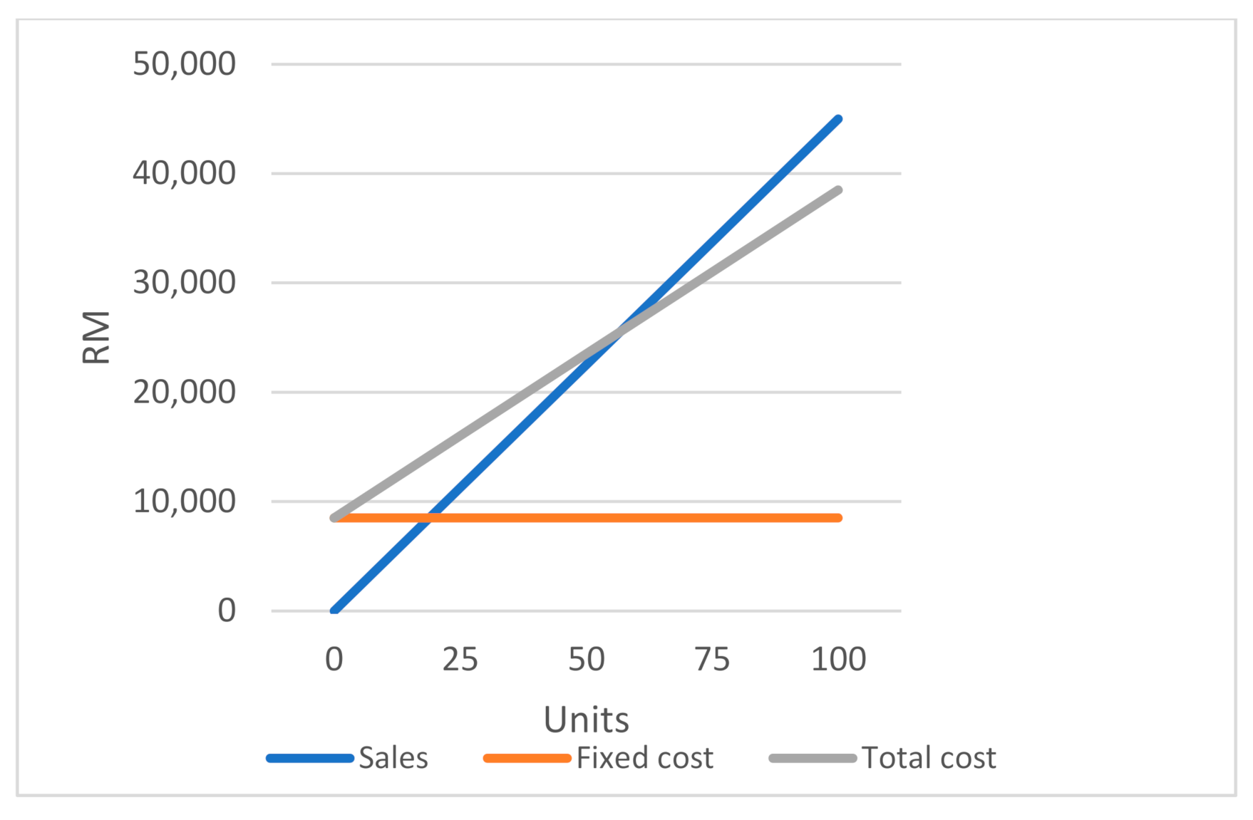
| Variable Cost Per Unit (Malaysian Ringgit, MYR) | |
|---|---|
| Wood | 80 |
| Steel | 115 |
| Slider | 50 |
| Hinge | 45 |
| Consumables (screws, lubricants, paint) | 10 |
| Total | 300 |
| Fixed Cost Per Month (Malaysian Ringgit, MYR) | |
|---|---|
| Labour (3 technicians with wage of 2500 MYR per month) | 7500 |
| Maintenance of tools and equipment per month | 1000 |
| Total | 8500 |
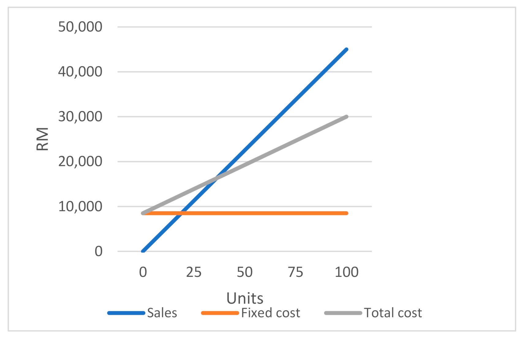
| Variable Cost Per Unit (Malaysian Ringgit, MYR) | |
|---|---|
| Wood | 60 |
| Steel | 85 |
| Slider | 35 |
| Hinge | 30 |
| Consumables (screws, lubricants, paint) | 5 |
| Total | 215 |
| Fixed Cost Per Month (Malaysian Ringgit, MYR) | |
|---|---|
| Labour (3 technicians with wage of 2500 MYR per month) | 7500 |
| Maintenance of tools and equipment per month | 1000 |
| Advertisements | 2000 |
| Total | 10,500 |
Publisher’s Note: MDPI stays neutral with regard to jurisdictional claims in published maps and institutional affiliations. |
© 2021 by the authors. Licensee MDPI, Basel, Switzerland. This article is an open access article distributed under the terms and conditions of the Creative Commons Attribution (CC BY) license (https://creativecommons.org/licenses/by/4.0/).
Share and Cite
Lim, S.H.; Ng, P.K. The Design and Development of a Foldable Wheelchair Stretcher. Inventions 2021, 6, 35. https://doi.org/10.3390/inventions6020035
Lim SH, Ng PK. The Design and Development of a Foldable Wheelchair Stretcher. Inventions. 2021; 6(2):35. https://doi.org/10.3390/inventions6020035
Chicago/Turabian StyleLim, Shao Hng, and Poh Kiat Ng. 2021. "The Design and Development of a Foldable Wheelchair Stretcher" Inventions 6, no. 2: 35. https://doi.org/10.3390/inventions6020035
APA StyleLim, S. H., & Ng, P. K. (2021). The Design and Development of a Foldable Wheelchair Stretcher. Inventions, 6(2), 35. https://doi.org/10.3390/inventions6020035