Tidal Supplementary Control Schemes-Based Load Frequency Regulation of a Fully Sustainable Marine Microgrid


Abstract
:1. Introduction
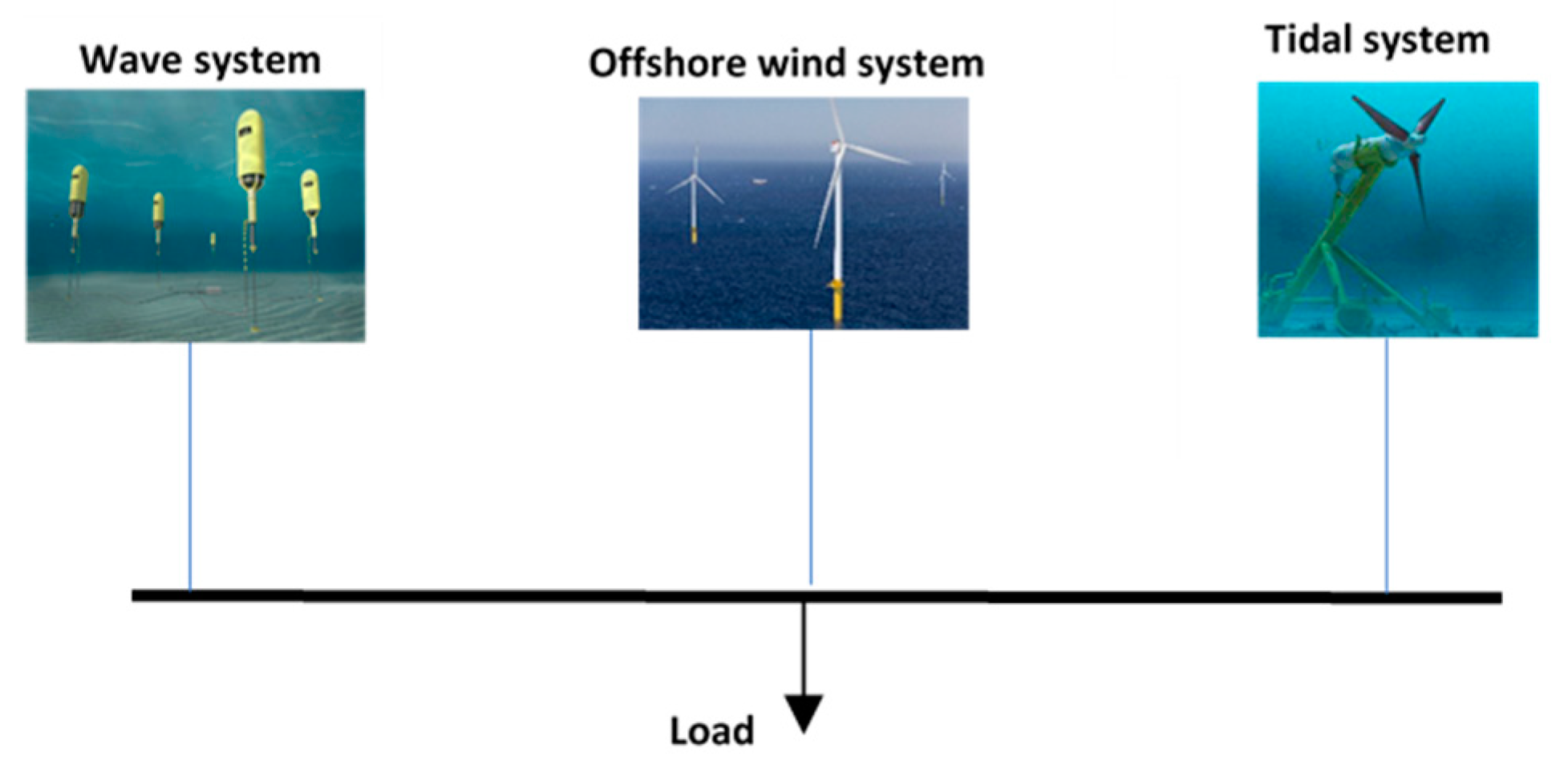
- Simulation and control of a 100% renewable energy microgrid including tidal, wave and offshore wind hybrid generation system.
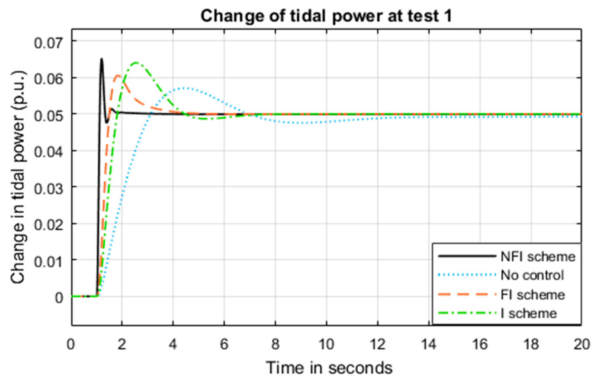
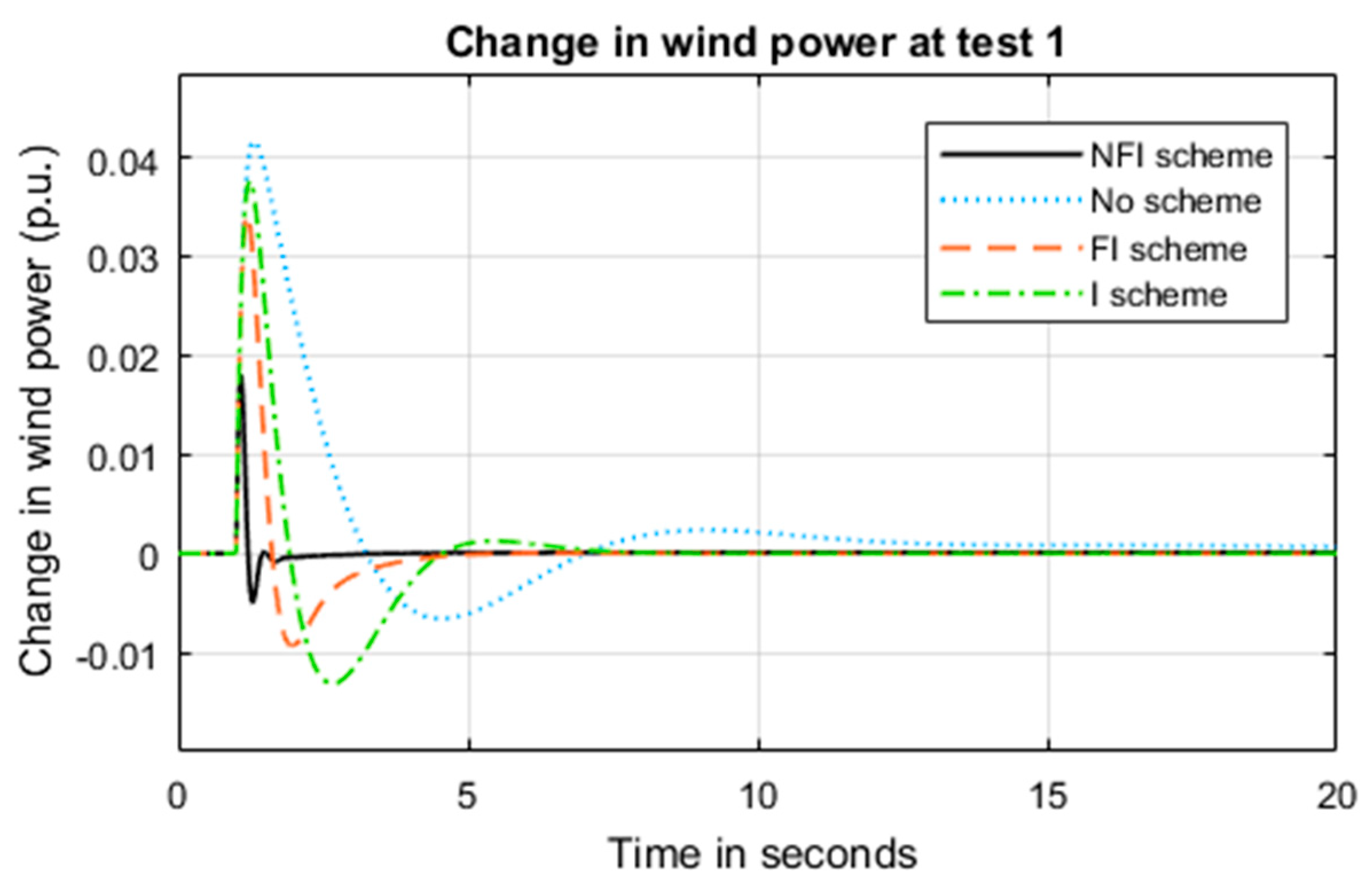
- The effect of different supplementary control schemes in terms of the integrator, fractional integrator, and non-linear fractional integrator on the dynamic performance of load frequency control (LFC) is examined.
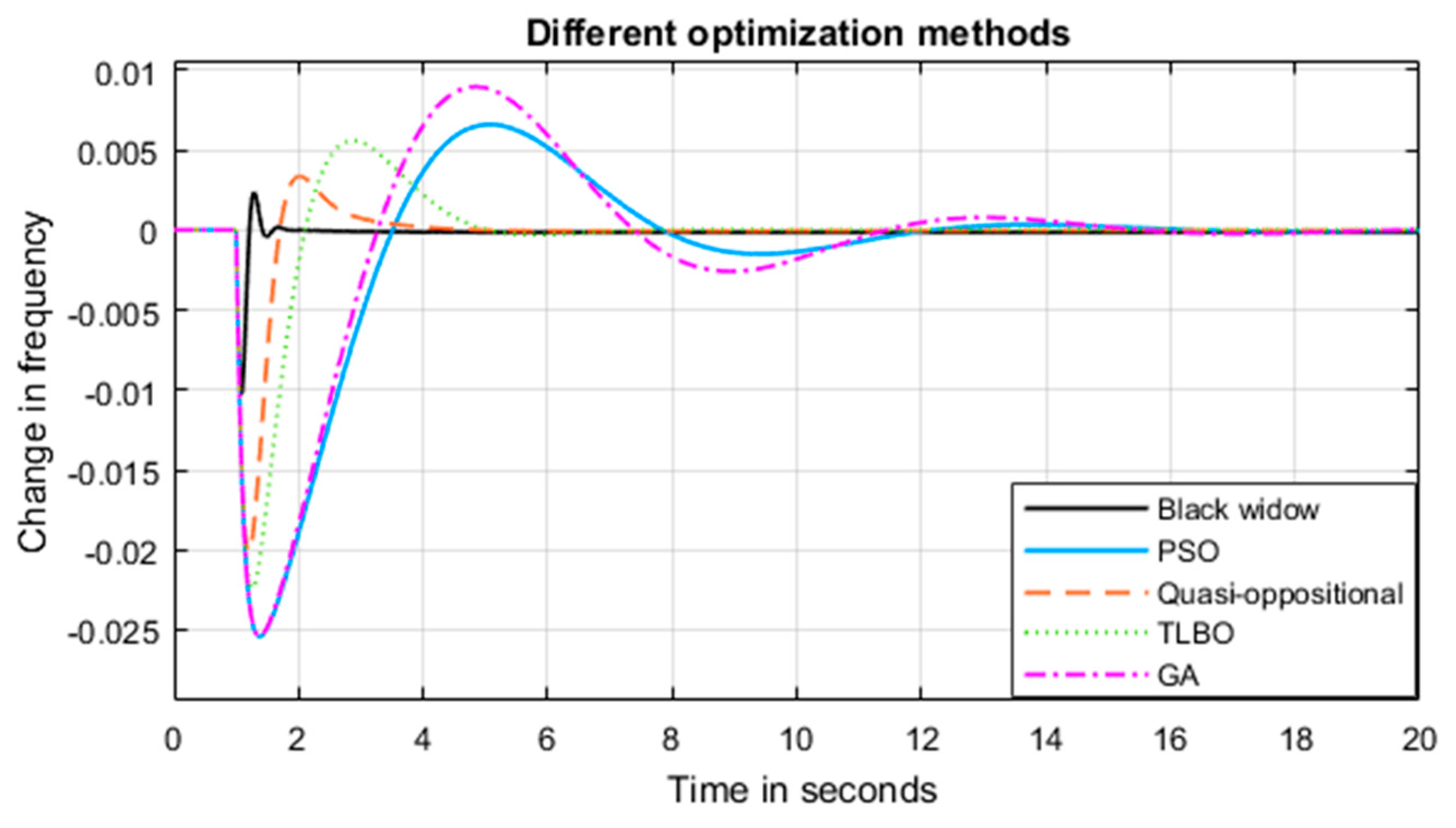
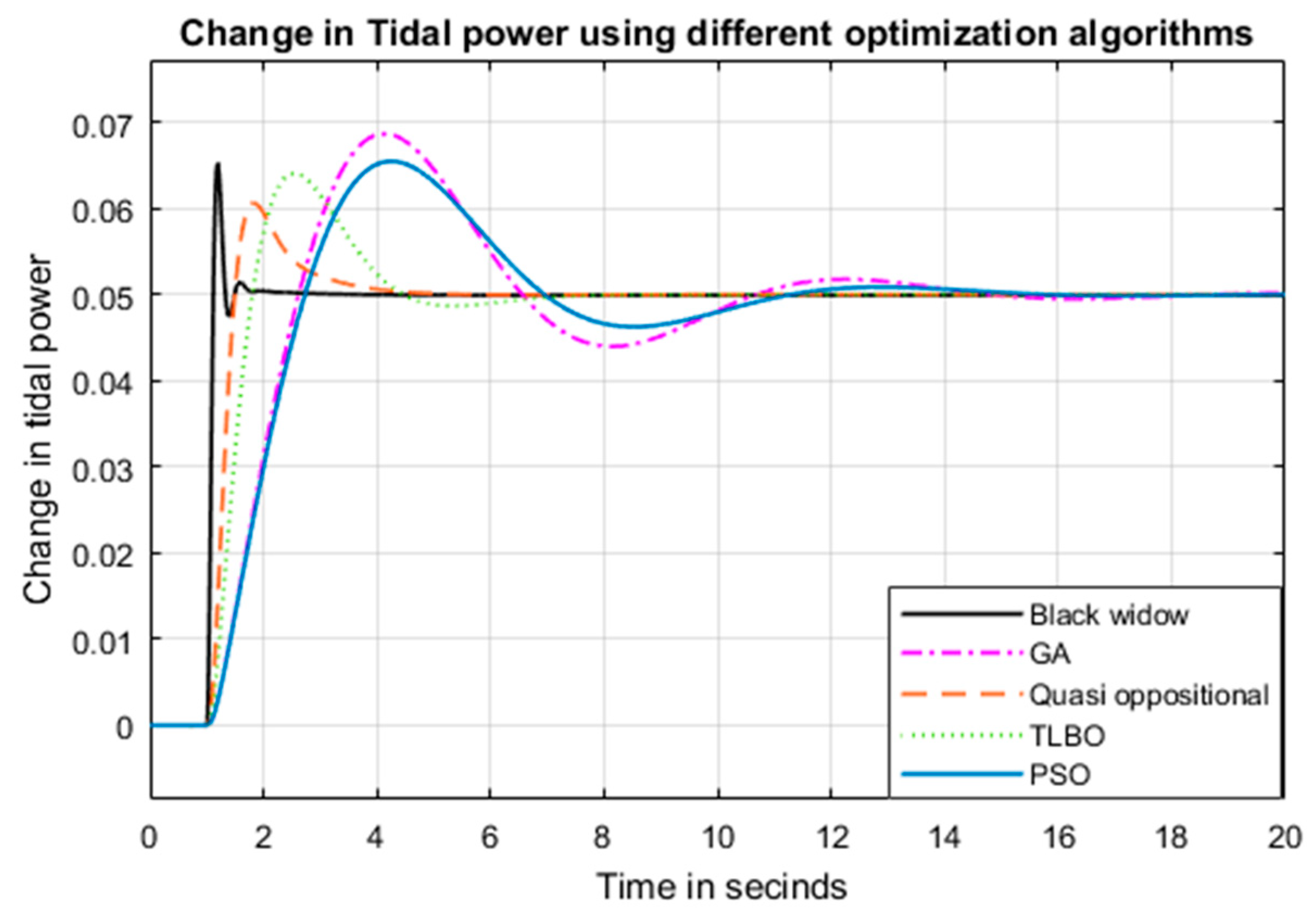
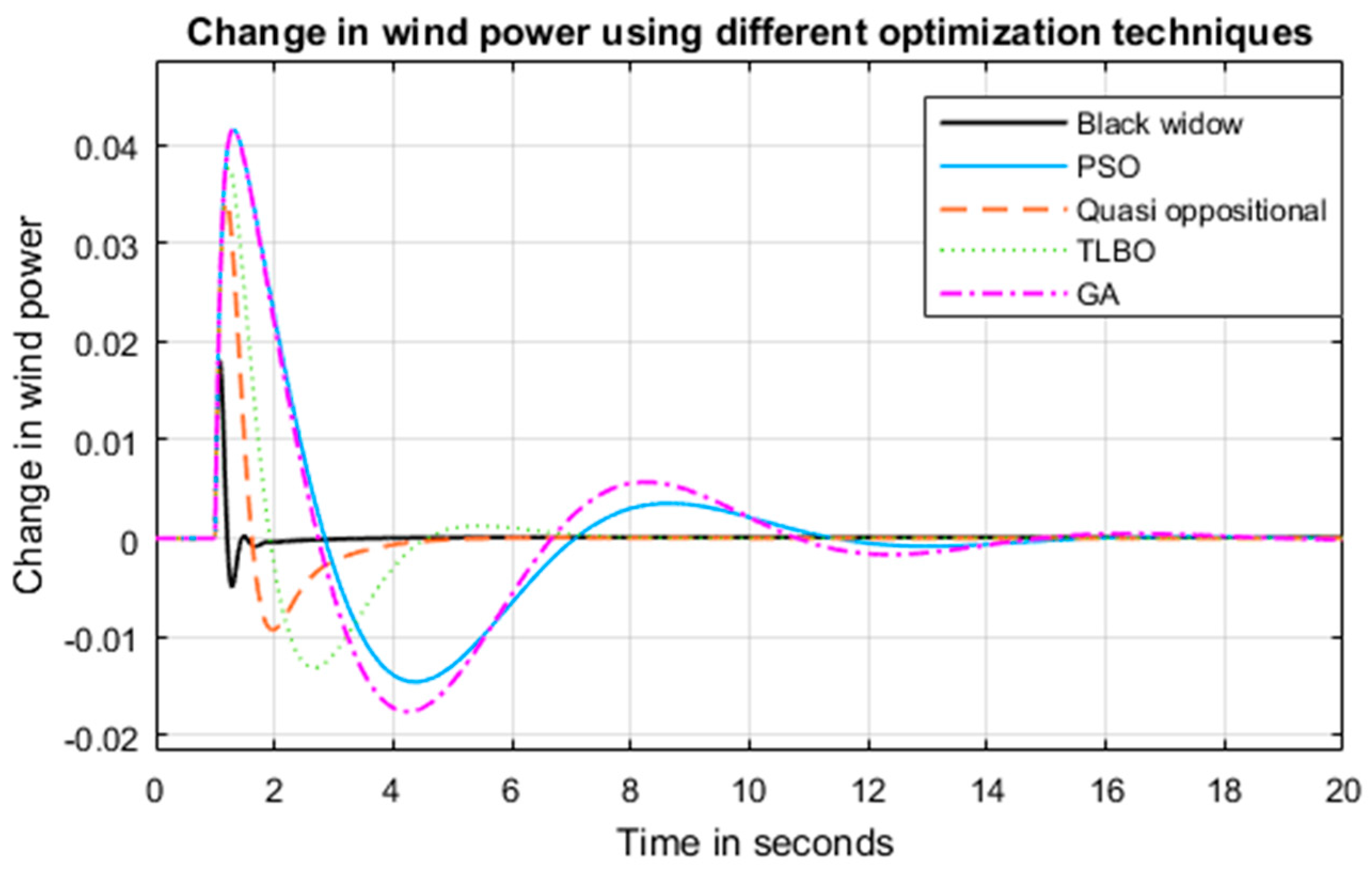
- Design of hybrid system controllers and tidal supplementary controller by using a novel black widow optimization technique and comparing it with other state-of-art optimization techniques.
2. Microgrid Modelling
2.1. Modeling of the Tidal Generating System
2.2. Modeling of Wave Generating System
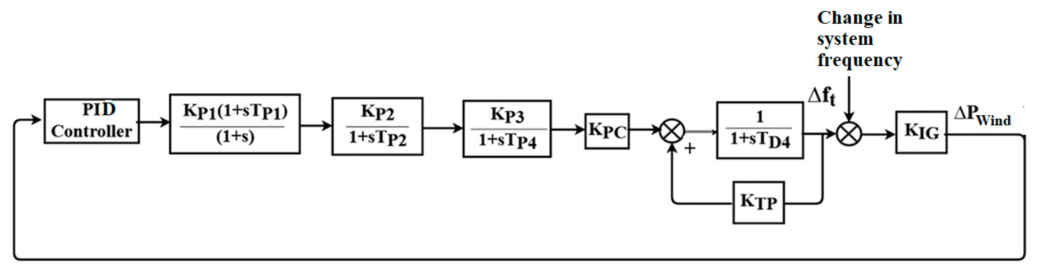
2.3. Modeling of Wind Generating System
2.4. Modeling of Microgrid
3. Controllers
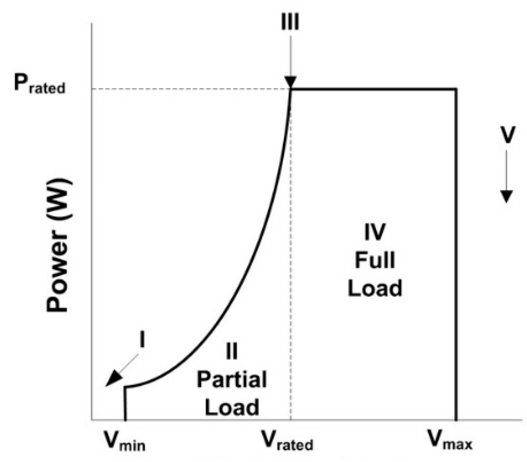
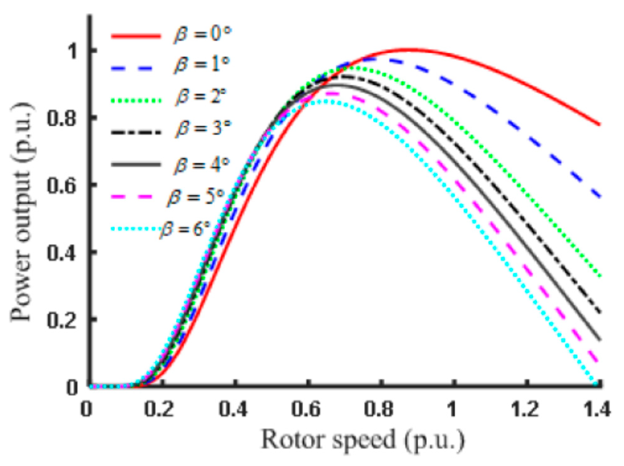
3.1. Blade Pitch Controllers
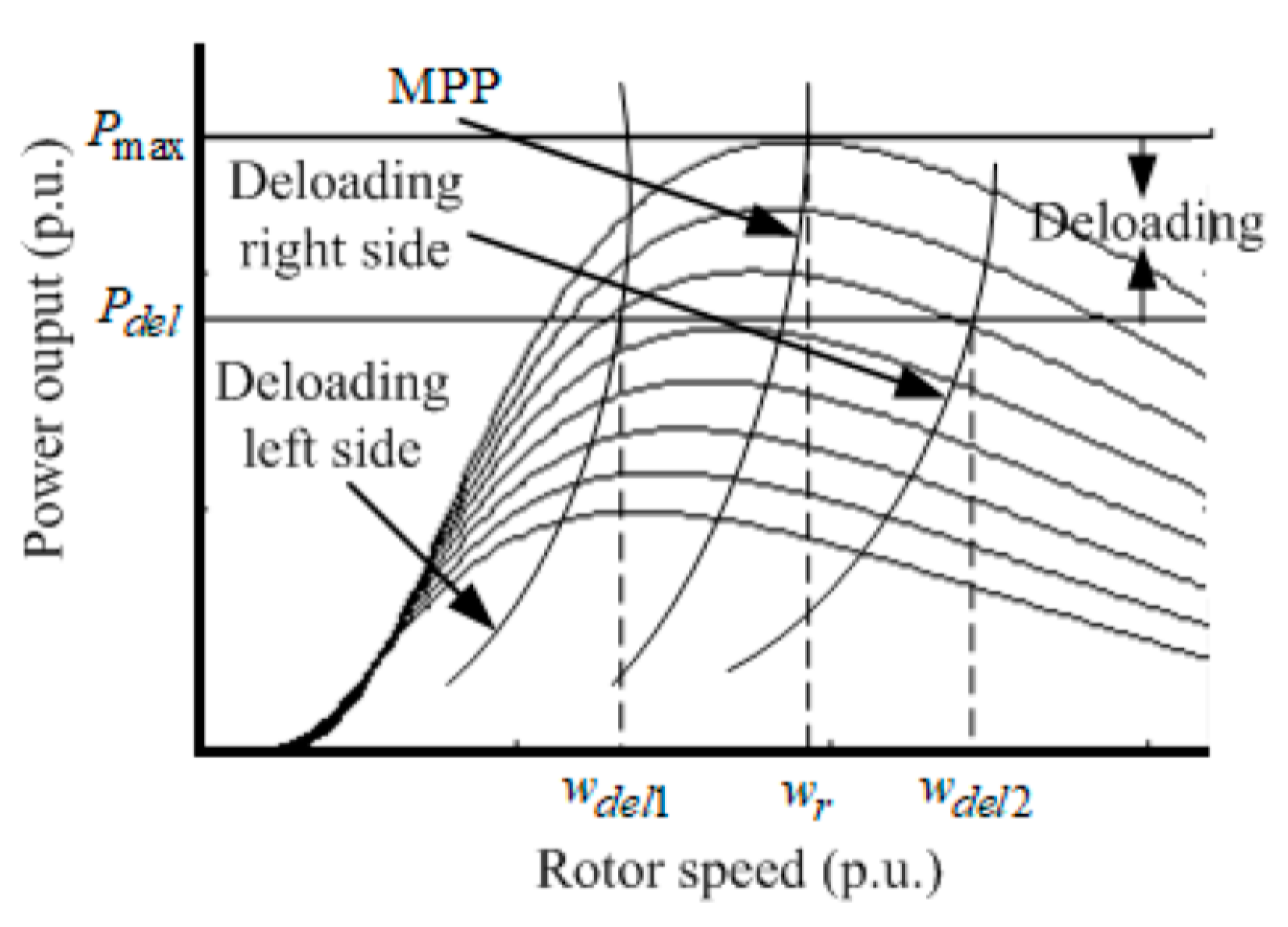
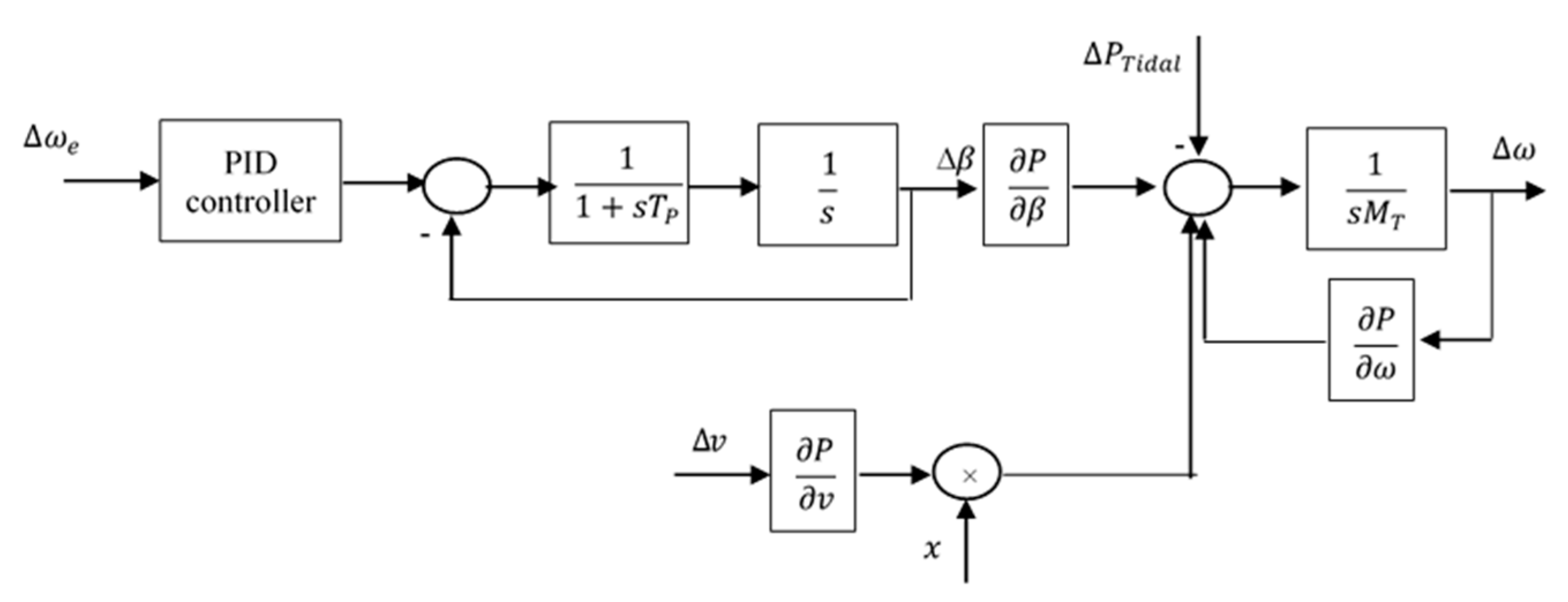
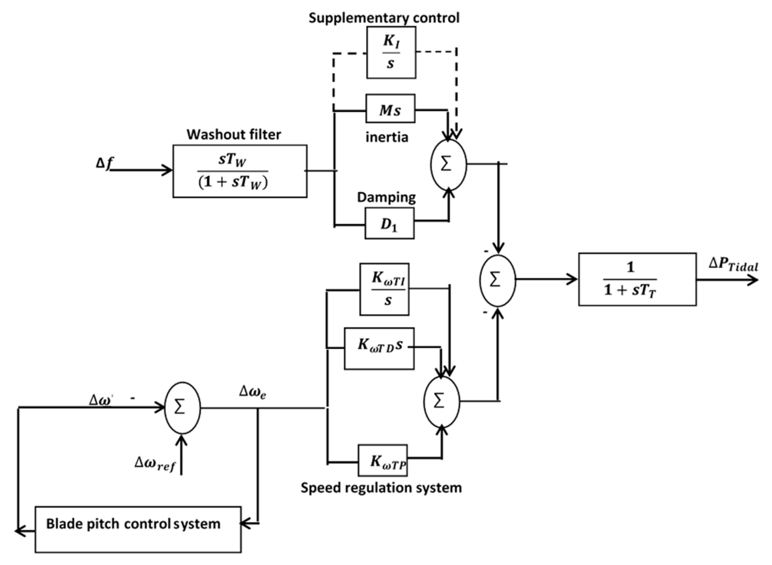
3.2. Tidal Speed Controller
3.3. Tidal Supplementary Control Schemes
- (i)
- Integrators (I scheme), which have the transfer function
- (ii)
- Fractional integrators (FI scheme), which have the transfer function =
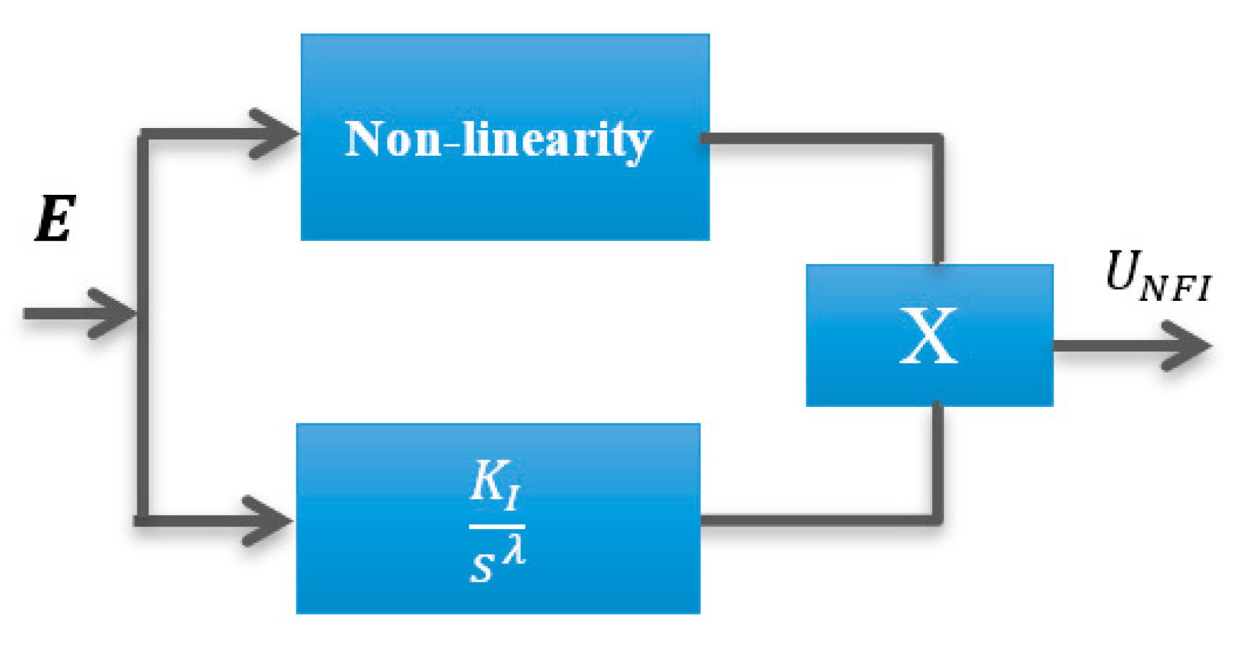
- (iii)
- Non-linear fractional integrators (NFI), which have the output
4. Control Design
4.1. Optimization Problem Definition
- i.
- Black widow
- ii.
- Quasi oppositional harmony search
- iii.
- Teaching and learning-based optimization
- iv.
- Particle swarm optimization
- v.
- Genetic algorithm
- Objective Function (): Minimization of integral absolute error (IAE) () and minimization of integral time absolute error (ITAE) ():
- Variables: PID control parameters, tidal additional damping, and inertia, in addition to tidal supplementary control schemes parameters.
- Constraints: G and λ.
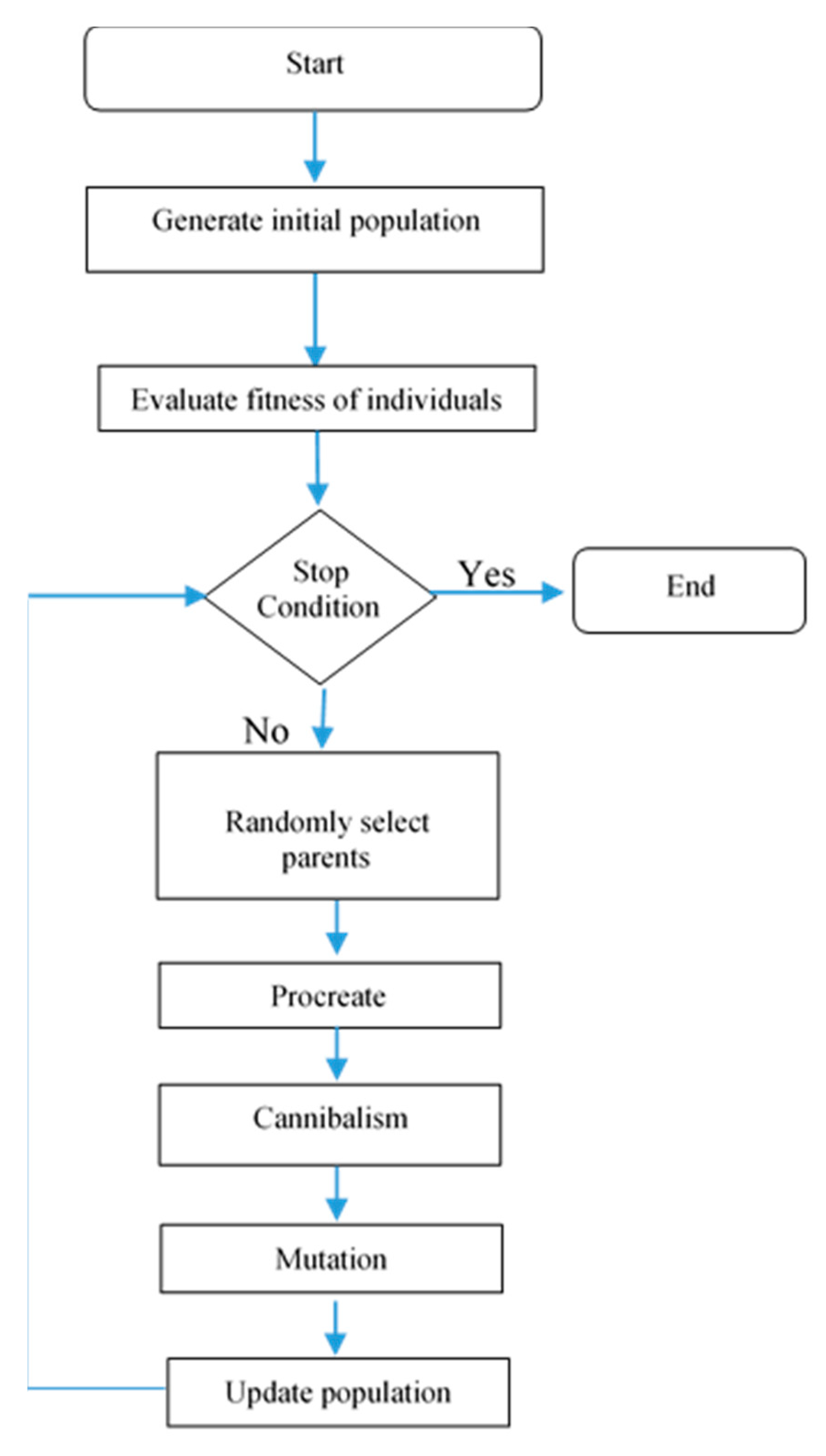
4.2. Black Widow Optimization
- Initial population: This is used in each optimization technique; it has other names, like chromosomes in the genetic algorithm and particle position in the particle swarm algorithm. In the black window, it has the name widow. To start the optimization, a candidate widow matrix with size Npop × Nvar is generated, where Nvar represents the solution of the problem array while Npop represents the number of populations.
- Procreate: In this step, an array called α is created such that the offspring is produced through (20) and (21):where and are parents, while and are offspring. The process repeated every .
- Cannibalism: There are three kinds of cannibalism: (a) sexual cannibalism, where the female black widow eats her husband; in the algorithm, we can identify male and female through their fitness function; (b) sibling cannibalism, where the strong spider siblings eat their weaker siblings; in the algorithm, the cannibalism rating is set according to the determined number of survivors; and (c) baby cannibalism, where baby spiders eat their mother; in the algorithm, strong and weak spider siblings are recognized through fitness value.
- Mutation: Random selection of Mutepop number of individuals. Mutepop is calculated according to the mutation rate.
- Convergence: The same concept of many algorithms comes in the proposed algorithm; three stop conditions may be used: (a) a predefined number of iterations; (b) the fitness value is almost constant for several iterations; and (c) the desired accuracy is reached.
5. Simulation Results
- Test 1: A step increase in the demand;
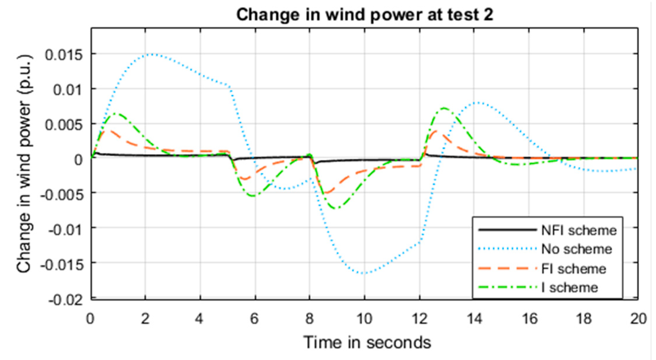
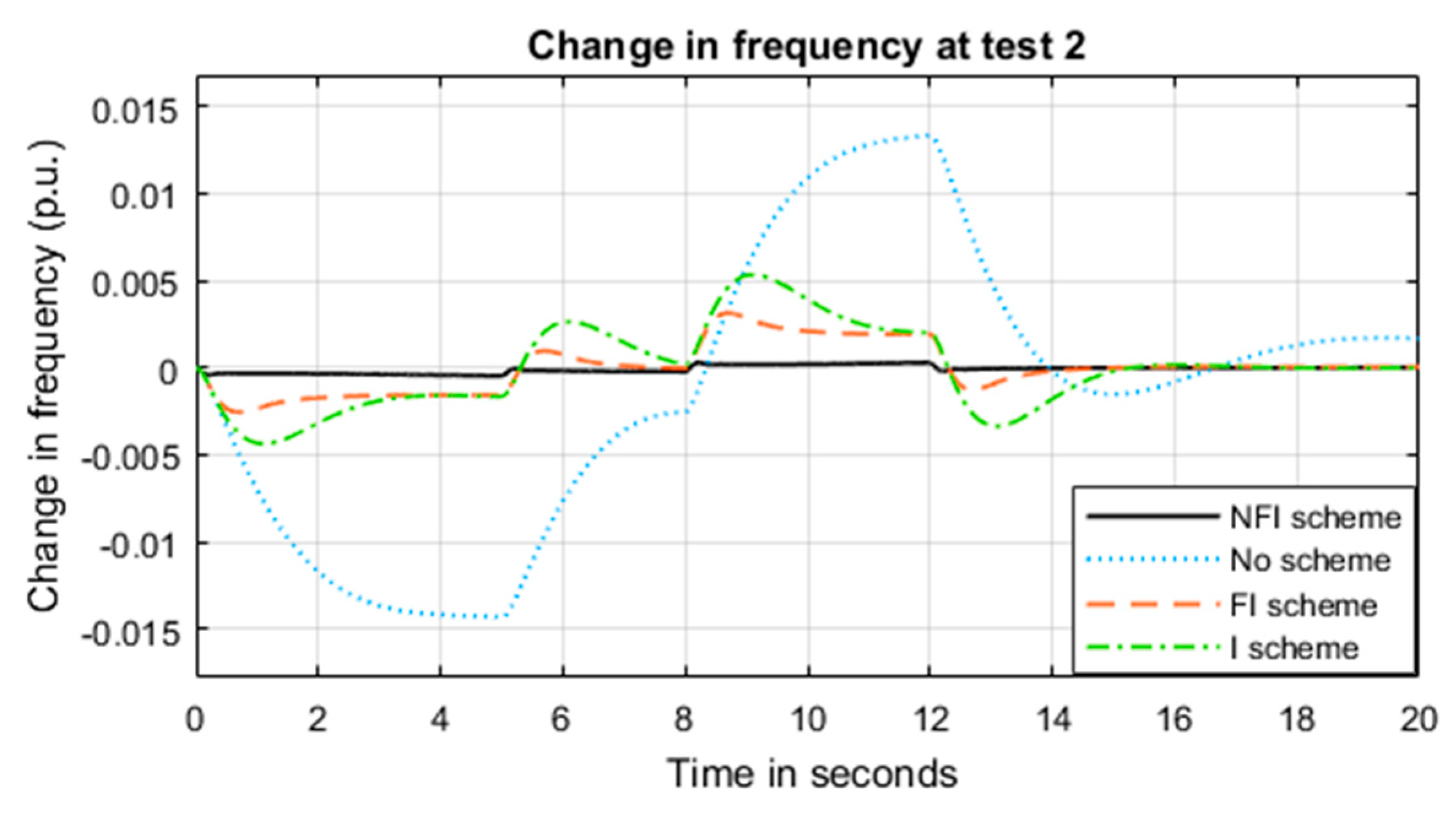
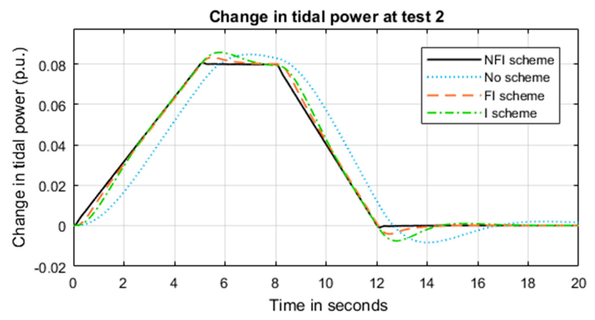
- Test 2: Real demand variation at a certain day;
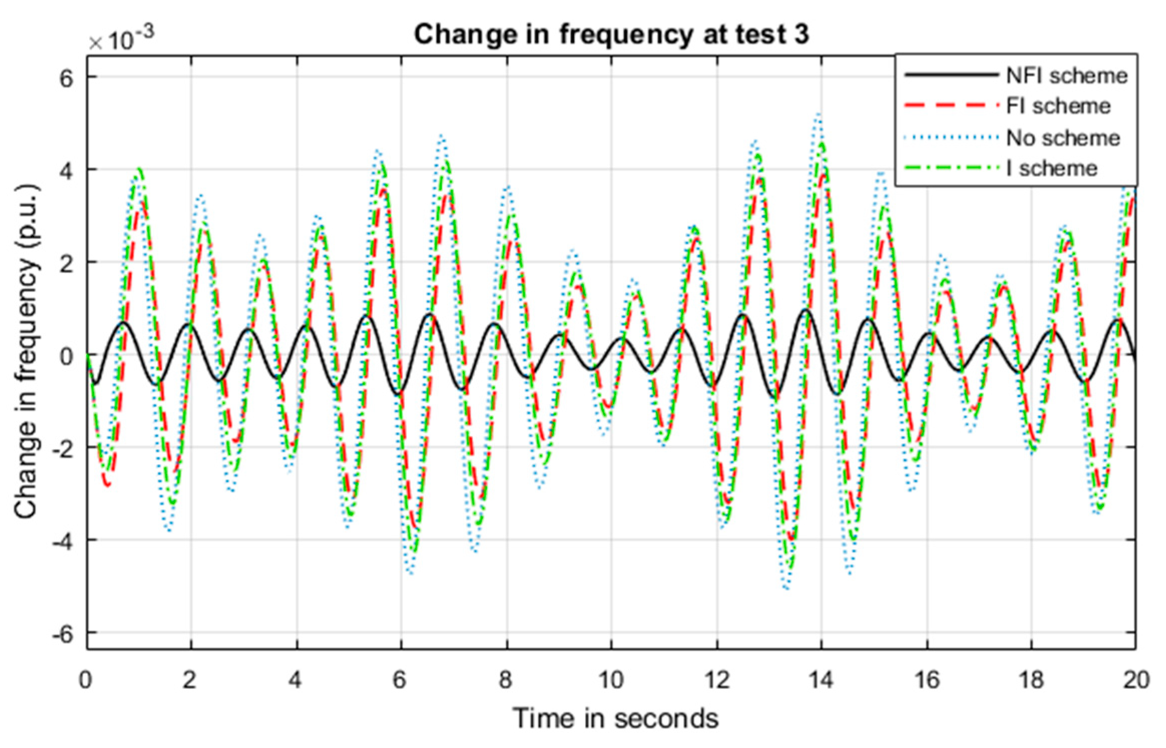
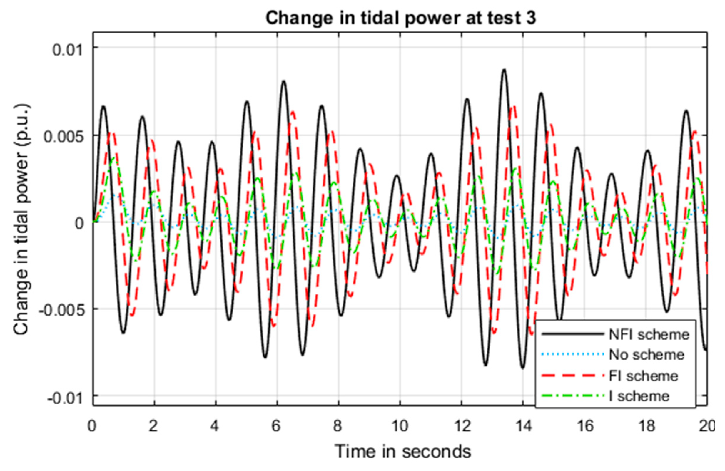
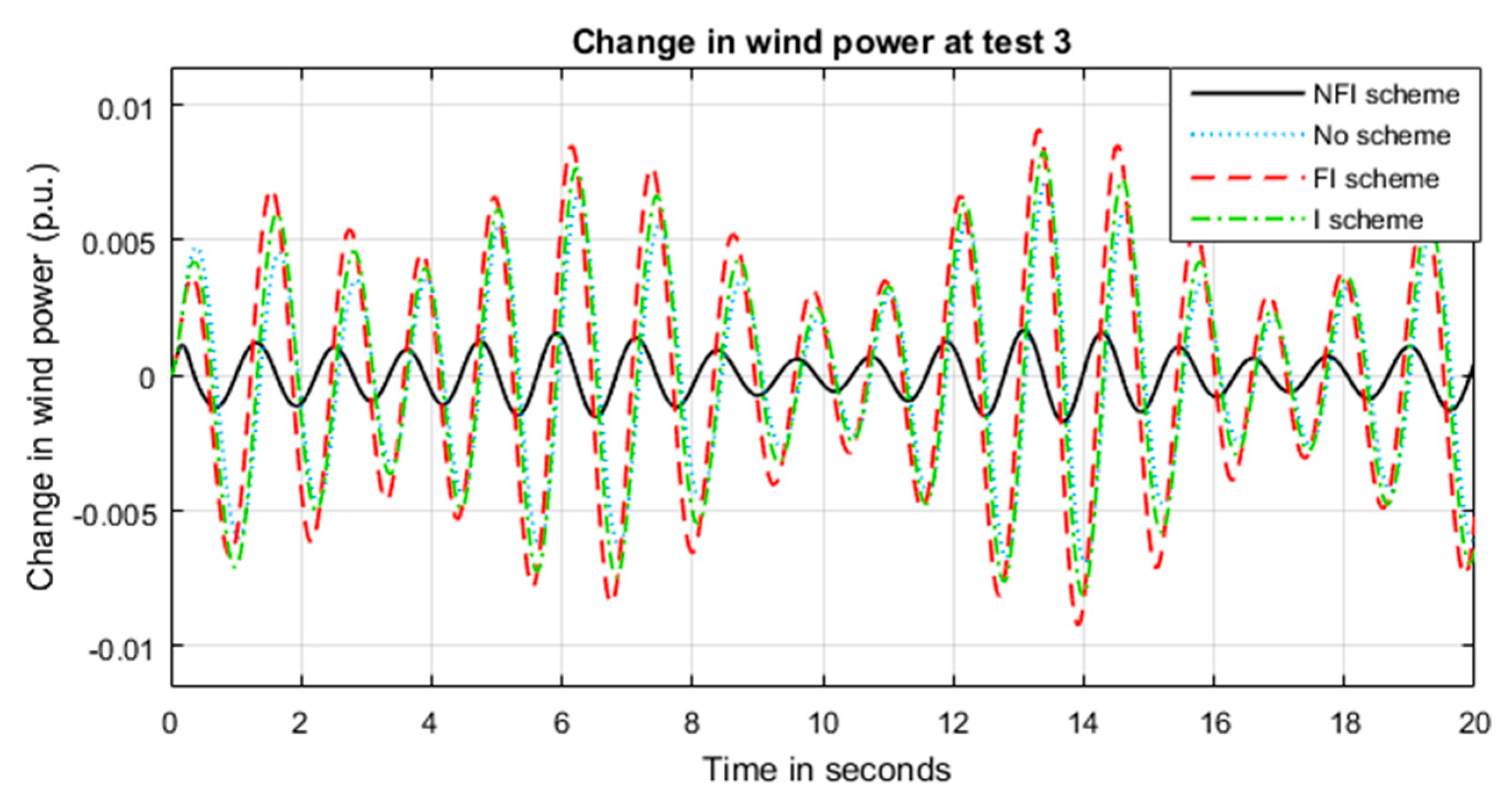
- Test 3: Sinewave variation of the wave generation system;
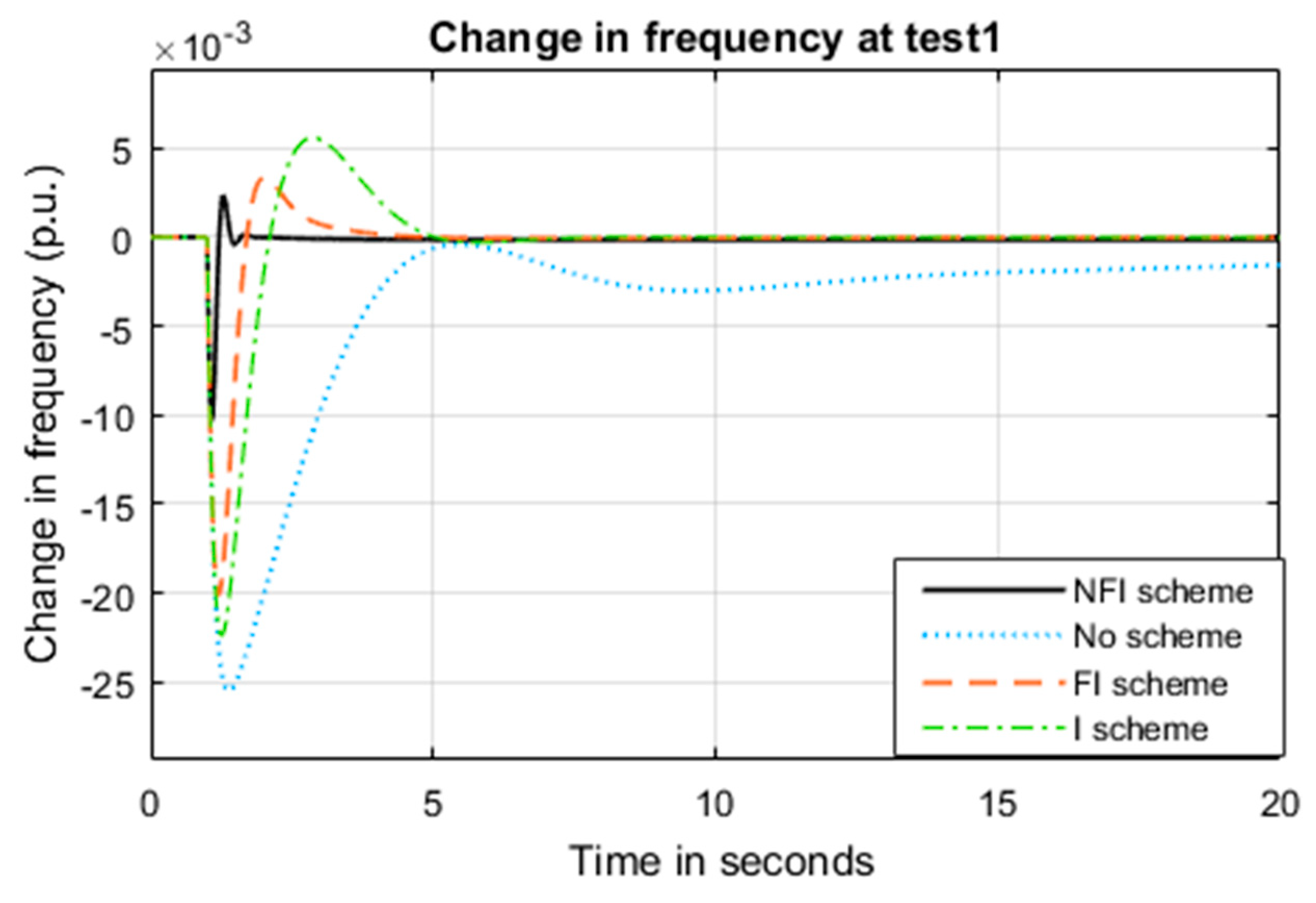
5.1. System Performance under Test 1
- Strategy a: System without supplementary control
- Strategy b: System with integrator supplementary control
- Strategy c: System with fractional integrator supplementary control
- Strategy d: System with non-linear fractional integrator supplementary control.
5.2. System Performance under Test 2
5.3. System Performance under Test 3
6. Conclusions
Author Contributions
Funding
Conflicts of Interest
Appendix A

| System | Parameters |
|---|---|
| Tidal | Capacity: 1 MW, rated rotor speed (ωr) = 13 rpm, tidal speed (V) = 2.4 m/s, TSR = 6.1, rotor radius (r) = 11.5 m, rotor blades = 3, blade length = 10.6 m, rotor position = upstream, MT = 0.3878 s, TP = 0.01 s, TT = 0.08 s, Tw = 6 s, angle limits: minimum = 0° and maximum = 90°, d1 = 0.18, d2 = 85, d3 = 0.38, d4 = 10.2, d5 = 6.2, d6 = 0.025, d7 = −0.043 |
| Wave | Capacity: 1 MW, Kwave = 1, Twave = 0.3 s, Tinv = Tconv = 0.01 s |
| Offshore wind | Capacity: 1 MW, Kp1 = 1.250, Kp2 = 1.000, Kp3 = 1.400, KTP = 0.0033, KIG = 0.9969, KPC = 0.0800, Tp1 = 0.6000 s, Tp2 = 0.0410, Tp3 = 1.000, TW = 4.000. |
| Microgrid | H = 5, D = 0.8, f = 50 Hz |
References
- Abdalla, O.H.; Fayek, H.H.; Abdel Ghany, A.M. Secondary Voltage Control Application in a Smart Grid with 100% Renewables. Inventions 2020, 5, 37. [Google Scholar] [CrossRef]
- Fayek, H.H. Voltage and Reactive Power Control of Smart Grid. Ph.D. Thesis, Helwan University, Helwan, Egypt, February 2019. [Google Scholar]
- Fayek, H.H. Load Frequency Control of a Power System with 100% Renewables. In Proceedings of the 2019 54th International Universities Power Engineering Conference (UPEC), Bucharest, Romania, 3–6 September 2019; pp. 1–6. [Google Scholar]
- Rourke, F.; Boyle, F.; Reynolds, A. Tidal energy update 2009. Appl. Energy 2010, 87, 398–409. [Google Scholar] [CrossRef]
- De Almeida, R.G.; Lopes, J.A.P. Participation of Doubly Fed Induction Wind Generators in System Frequency Regulation. IEEE Trans. Power Syst. 2007, 22, 944–950. [Google Scholar] [CrossRef] [Green Version]
- Zaheeruddin; Singh, K. Primary frequency regulation of a microgrid by deloaded tidal turbines. Soft Comput. 2020, 24, 14667. [Google Scholar] [CrossRef]
- Whitby, B.; Ugalde-Loo, C.E. Performance of Pitch and Stall Regulated Tidal Stream Turbines. IEEE Trans. Sustain. Energy 2013, 5, 64–72. [Google Scholar] [CrossRef]
- Bryans, A.; Fox, B.; Crossley, P.; O’Malley, M. Impact of Tidal Generation on Power System Operation in Ireland. IEEE Trans. Power Syst. 2005, 20, 2034–2040. [Google Scholar] [CrossRef]
- Mauricio, J.M.; Marano, A.; Gomez-Exposito, A.; Ramos, J.L.M. Frequency Regulation Contribution through Variable-Speed Wind Energy Conversion Systems. IEEE Trans. Power Syst. 2009, 24, 173–180. [Google Scholar] [CrossRef]
- Da, Y.; Khaligh, A. Hybrid offshore wind and tidal turbine energy harvesting system with independently controlled rectifiers. In Proceedings of the 2009 35th Annual Conference of IEEE Industrial Electronics, Porto, Portugal, 3–5 November 2009; pp. 4577–4582. [Google Scholar]
- Rahman, M.L.; Shirai, Y. Hybrid offshore-wind and tidal turbine (HOTT) energy conversion I (6-pulse GTO rectifier and inverter). In Proceedings of the 2008 IEEE International Conference on Sustainable Energy Technologies, Singapore, 24–27 November 2008; pp. 650–655. [Google Scholar]
- Huang, J.; Yang, J.; Xie, D.; Wu, D. Optimal Sliding Mode Chaos Control of Direct-Drive Wave Power Converter. IEEE Access 2019, 7, 90922–90930. [Google Scholar] [CrossRef]
- Hasanien, H.M. Transient Stability Augmentation of a Wave Energy Conversion System Using a Water Cycle Algorithm-Based Multiobjective Optimal Control Strategy. IEEE Trans. Ind. Inform. 2018, 15, 3411–3419. [Google Scholar] [CrossRef]
- Ghoshal, S. Optimizations of PID gains by particle swarm optimizations in fuzzy based automatic generation control. Electr. Power Syst. Res. 2004, 72, 203–212. [Google Scholar] [CrossRef]
- Das, D.C.; Roy, A.; Sinha, N. GA based frequency controller for solar thermal–diesel–wind hybrid energy generation/energy storage system. Int. J. Electr. Power Energy Syst. 2012, 43, 262–279. [Google Scholar] [CrossRef]
- Rao, R.V.; Savsani, V.J.; Vakharia, D.P. Teaching–learning-based optimization: A novel method for constrained mechanical design optimization problems. Comput. Des. 2011, 43, 303–315. [Google Scholar] [CrossRef]
- Pan, Q.-K.; Suganthan, P.; Tasgetiren, M.F.; Liang, J. A self-adaptive global best harmony search algorithm for continuous optimization problems. Appl. Math. Comput. 2010, 216, 830–884. [Google Scholar] [CrossRef]
- Hayyolalam, V.; Kazem, A.A.P. Black Widow Optimization Algorithm: A novel meta-heuristic approach for solving engineering optimization problems. Eng. Appl. Artif. Intell. 2020, 87, 103249. [Google Scholar] [CrossRef]
- Rawat, S.; Singh, S.; Gaur, K. Load frequency control of a hybrid renewable power system with fuel cell system. In Proceedings of the 2014 6th IEEE Power India International Conference (PIICON), Delhi, India, 5–7 December 2014; pp. 1–6. [Google Scholar] [CrossRef]
- Das, D.C.; Sinha, N.; Roy, A.K. Automatic Generation Control of an Organic Rankine Cycle Solar-Thermal/Wind-Diesel Hybrid Energy System. Energy Technol. 2014, 2, 721–731. [Google Scholar] [CrossRef]
- Fayek, H.H.; El-Zoghby, H.M.; Ghany, A.A. Design of Robust PID Controllers Using H∞ Technique to Control the Frequency of Wind-Diesel-Hydro Hybrid Power System. In Proceedings of the International Conference on Electrical Engineering, San Francisco, CA, USA, 22–24 October 2014. [Google Scholar]
- Fayek, H.H. Robust Controllers Design of Hybrid System Load Frequency Control. Master’s Thesis, Helwan University, Helwan, Egypt, 2014. [Google Scholar]
- Fayek, H.H.; Shenouda, A. Design and Frequency Control of Small Scale Photovoltaic Hydro Pumped Storage System. In Proceedings of the 2019 IEEE 2nd International Conference on Renewable Energy and Power Engineering (REPE), Toronto, ON, Canada, 2–4 November 2019; pp. 32–37. [Google Scholar]
- Kumar, A.; Shankar, G. Quasi-oppositional harmony search algorithm based optimal dynamic load frequency control of a hybrid tidal–diesel power generation system. IET Gener. Transm. Distrib. 2018, 12, 1099–1108. [Google Scholar] [CrossRef]
- Veronica, A.J.; Kumar, N.S.; Gonzalez-Longatt, F. Design of Load Frequency Control for a Microgrid Using D-partition Method. Int. J. Emerg. Electr. Power Syst. 2020, 21, 20190175. [Google Scholar] [CrossRef]
- Chen, M.-R.; Zeng, G.-Q.; Dai, Y.-X.; Lu, K.-D.; Bi, D.-Q. Fractional-Order Model Predictive Frequency Control of an Islanded Microgrid. Energies 2019, 12, 84. [Google Scholar] [CrossRef] [Green Version]
- Hefiri, K.; Garrido, A.J.; Rusu, E.; Bouallègue, S.; Haggège, J.; Garrido, I. Fuzzy Supervision Based-Pitch Angle Control of a Tidal Stream Generator for a Disturbed Tidal Input. Energies 2018, 11, 2989. [Google Scholar] [CrossRef] [Green Version]


| Mode No. | Condition | Operation |
|---|---|---|
| I | V ≤ Vmin | No power generation with pitch angle setting 90 degrees. |
| II | Vmin < V ≤ Vrated | Optimum power extraction from the turbine to reach optimum efficiency, Blade pitch angle is set at 4 degrees in this work |
| III | Vrated < V ≤ Vmax | Constant power operation turbine, blade pitch angle is varied from 4 degrees to 90 degrees to avoid overload. |
| IV | V > Vmax | No power output and blade pitch angle is set at 90 degrees. |
| Method | ITAE | IAE | Number of Iterations | |||||
|---|---|---|---|---|---|---|---|---|
| Ush | Osh | ts | tp | |||||
| Black widow | 0.0059 | 0.0011 | 0.39 | 15 | −0.01 | 0.0025 | 1.75 | 1.5 |
| Quasi-oppositional | 0.0064 | 0.0016 | 0.42 | 21 | −0.02 | 0.003 | 3.5 | 2 |
| TLBO | 0.0071 | 0.0019 | 0.48 | 18 | −0.022 | 0.006 | 4.5 | 2.8 |
| PSO | 0.0085 | 0.0026 | 0.61 | 25 | −0.025 | 0.007 | 15 | 4 |
| GA | 0.0089 | 0.0027 | 0.64 | 23 | −0.025 | 0.009 | 15 | 4 |
| Control Scheme | Supplementary Control | Tidal Blade Pitch Controller | Tidal Speed Regulator | Wind Blade Pitch Controller | ||||||||||
|---|---|---|---|---|---|---|---|---|---|---|---|---|---|---|
| No scheme | 150 | 147 | none | none | none | 10 | 3 | 0.4 | 50 | 17 | 12 | 16 | 5 | 0.3 |
| I scheme | 122 | 85 | 10 | none | none | 17 | 14 | 11 | 14 | 5 | 4 | 17 | 1 | 0.2 |
| FI scheme | 146 | 75 | 7 | 0.43 | none | 11 | 9 | 0.16 | 6 | 4 | 1.4 | 8 | 5 | 2 |
| NFI scheme | 98 | 56 | 13 | 0.64 | 0.72 | 14 | 7 | 1.14 | 8 | 3 | 0.57 | 21 | 17 | 8 |
| Control Scheme | = 0.8 | = 1 | = 1.2 | = 1.4 | ||||||||
|---|---|---|---|---|---|---|---|---|---|---|---|---|
| ITAE | IAE | ts | ITAE | IAE | ts | ITAE | IAE | ts | ITAE | IAE | ts | |
| No scheme | 0.087 | 0.061 | 17 | 0.079 | 0.050 | 15 | 0.071 | 0.038 | 12 | 0.059 | 0.032 | 11 |
| I scheme | 0.064 | 0.052 | 5 | 0.058 | 0.043 | 4.3 | 0.049 | 0.035 | 3.7 | 0.041 | 0.026 | 3.4 |
| FI scheme | 0.053 | 0.039 | 4.2 | 0.041 | 0.031 | 3.9 | 0.036 | 0.024 | 3.1 | 0.023 | 0.017 | 2.8 |
| NFI scheme | 0.031 | 0.022 | 1.8 | 0.029 | 0.018 | 1.7 | 0.024 | 0.014 | 1.6 | 0.018 | 0.009 | 1.5 |
Publisher’s Note: MDPI stays neutral with regard to jurisdictional claims in published maps and institutional affiliations. |
© 2020 by the authors. Licensee MDPI, Basel, Switzerland. This article is an open access article distributed under the terms and conditions of the Creative Commons Attribution (CC BY) license (http://creativecommons.org/licenses/by/4.0/).
Share and Cite
Fayek, H.H.; Mohammadi-Ivatloo, B. Tidal Supplementary Control Schemes-Based Load Frequency Regulation of a Fully Sustainable Marine Microgrid. Inventions 2020, 5, 53. https://doi.org/10.3390/inventions5040053
Fayek HH, Mohammadi-Ivatloo B. Tidal Supplementary Control Schemes-Based Load Frequency Regulation of a Fully Sustainable Marine Microgrid. Inventions. 2020; 5(4):53. https://doi.org/10.3390/inventions5040053
Chicago/Turabian StyleFayek, Hady H., and Behnam Mohammadi-Ivatloo. 2020. "Tidal Supplementary Control Schemes-Based Load Frequency Regulation of a Fully Sustainable Marine Microgrid" Inventions 5, no. 4: 53. https://doi.org/10.3390/inventions5040053
APA StyleFayek, H. H., & Mohammadi-Ivatloo, B. (2020). Tidal Supplementary Control Schemes-Based Load Frequency Regulation of a Fully Sustainable Marine Microgrid. Inventions, 5(4), 53. https://doi.org/10.3390/inventions5040053