Article

A Topology of DC-DC Converter Based on Multi-Winding Transformer for Grid Integration of Multiple Renewable Energy Resources

by
Mohammad Jafari
* and
Zahra Malekjamshidi
School of Electrical and Data Engineering, University of Technology Sydney, 15 Broadway, Sydney 2007, NSW, Australia
*
Author to whom correspondence should be addressed.
Inventions 2020, 5(3), 31; https://doi.org/10.3390/inventions5030031
Submission received: 7 June 2020 / Revised: 4 July 2020 / Accepted: 7 July 2020 / Published: 9 July 2020
(This article belongs to the Special Issue Advances in Grid Integration of Renewable Energy Systems)

Abstract

:
This paper presents a topology of a multi-port phase shift converter for integration with a photovoltaic (PV) system, a wind turbine generator, and a battery to supply a grid-connected domestic load. The main advantage of the topology is using a multi-winding high-frequency transformer (MWHFT) to integrate the input and outputs of the system. In contrast with the case of using a common electrical bus, using MWHFT presents several advantages, such as isolating the converter ports, the easier matching of different voltage levels of the converter ports by adjusting turns ratio, simpler power flow control between the converter ports by applying leading or lagging phase shift angles, and eliminating the leakage current flow through the PV panels from the utility grid. A detailed analysis of the proposed topology and the control system is presented. A numerical simulation of the proposed system is carried out to confirm the system operation and control technique. The experimental tests have been conducted on a prototype converter to approve the proposed system performance.

1. Introduction

Multiport converters have been an attractive research topic over the past decade, due to their application in the integration of several renewable energy sources into a single power processing unit. Therefore, a large number of multi-port converter topologies has been introduced in the literature so far [1,2,3,4,5,6,7,8,9]. The proposed topologies can be classified, as the topologies operate based on the series or parallel connection of small conversion cells [10], a time-sharing concept [11,12,13] and magnetic flux additivity [14]. Furthermore, some of them have the property of bidirectional power flow between the connected ports, while others are unidirectional only [15]. Among the proposed topologies, those that are based on a magnetic-coupling through a multi-winding transformer have attracted more attention, due to their excellent features in terms of flexibility, safety and isolation, as well as their operational power range. This provides an isolation between the ports, and facilitates the connecting of several sources with substantially different operating voltages, thanks to the transformer turns ratio [16]. On the other hand, a simpler power flow control can be achieved by using a phase shift control technique [17,18,19]. A complete study on the magnetically coupled multi-port converters has been presented in [16,17,18,19,20]. It should be noted that the system operation and design of the multi-winding high-frequency transformer become very complex in the case of a large number of windings [21,22,23,24]. A magnetically coupled converter with two inputs and one output is presented in [25], where instead of combining input DC sources in electric form, they are combined in magnetic form by adding the produced magnetic fluxes together using the magnetic core of the multi-winding transformer. The power flow in the proposed converter has been drawn from two different DC sources, and delivered to the load individually and simultaneously [16]. The converter is able to accommodate the voltage variations of the sources by using the current-fed H-bridge converters. However, the topology is not able to maintain a bidirectional power flow, and the current stress of the switching devices is high [16]. A three-port converter was proposed in [26] to couple a fuel cell and a battery system, and the topology was also recommended in [27] for application in an uninterruptible power supply (UPS). Using batteries along with the renewable energy sources increases the energy management flexibility [27,28]. However, many technical points need to be considered when using batteries for energy storage [29]. As another application, a three-port converter is introduced using two current-fed ports to interface several energy storage elements, such as batteries and super capacitors [30]. As a recent application, the magnetically coupled multi-port converter is used in a hybrid energy system for a residential house [17,19]. The proposed topology enables the system to operate based on the different control techniques and energy management scenarios [16].
The common technique of coupling converter ports to the multi-winding transformer employs the H-bridge DC-AC converters to generate a high-frequency rectangular waveform from the input DC voltage, as discussed in more detail in [16,31,32]. The power flow control can then be realized by applying leading or lagging phase shift between the generated waveforms. The topology is suitable for medium-power applications (a few kilowatts), and the main advantages are a simultaneous bidirectional power transfer between any input to any output, the possibility of soft-switched operation for all coupled H-bridges, galvanic isolation between the input and outputs, and the capability of matching different voltage levels using transformer turns ratio and centralized control [16]. However, there are some disadvantages, such as the large number of switching devices, a limited soft-switched region when operating with wide input voltage ranges, and the complexity of the transformer design [16,17]. The problem of soft-switching range in the case of using variable DC sources as the input source can be reduced by applying duty cycle control to the generated waveforms, or using current-fed H-bridge converters instead of simple H-bridges [33]. In [34], the authors studied some other bridge converters with possible applicability in the phase shift converters. To analyze the multi-port phase shift converters, the multi-port topology can be decomposed into the simple dual active bridge (DAB) converter topologies, as is discussed in [6,16,35]. The DAB converter was proposed by Kheraluwala and Divan in [36], and more detailed analysis was provided in [37]. The topology has been widely studied in the literature, and modified considerably over the last decade. The improvement in the switching conditions of the bridge converter are studied in [38,39], and the problem of circulating reactive power and the possible solutions have been studied [40,41].
In this paper, a multi-port phase shift converter topology, based on a multi-winding high-frequency transformer, for integrating a PV system, a wind turbine generator and a battery, is introduced to supply a set of grid-connected domestic loads. The system is designed to transfer the power from the renewable energy sources to the battery, load and grid in the form of magnetic flux, using a multi-winding transformer. In contrast to the DC and AC electrical bus, using a multi-winding transformer presents several advantages. It isolates the converter ports, and consequently the sources, loads and the utility grid, which improves the system safety. Besides, the difference in the voltage levels of the converter ports is matched by adjusting the turns ratio of the transformer. Therefore, the low-voltage DC at the renewable energy ports can be stepped up easily by proper selection of the transformer turns ratio, instead of using voltage boost switching circuits with high-voltage stress and switching losses. In addition, it provides a simple power flow path between the converter ports, which can be easily controlled by applying leading or lagging phase shift angles. Furthermore, using a transformer in the PV port eliminates the possibility of flowing leakage DC or AC currents through the panels from the utility grid, which reduces the system safety and also degrades the solar panel efficiency over time. The power also can be supplied from the grid to the battery in the reverse direction when it is required, which increases the system’s flexibility compared to the other proposed multi-port converter topologies. The system operation principle is discussed in detail and the control technique is also studied. A numerical simulation of the proposed topology and control technique is carried out using PSIM software, and the experimental tests are conducted to show the validity of the system operation and the proposed control techniques.

2. Materials and Methods

The topology of the proposed Multi-port converter is presented in Figure 1. As illustrated in the figure, the converter topology contains four current-fed H-bridge DC-AC converters linked to a multi-winding transformer at one side, and to a DC source at the other side. The H-bridge converter in port one is connected to a PV generation system, port two to a wind turbine generator, port three to a battery and port four to a high-voltage DC bus, followed by a single-phase inverter. In this structure, the transformer core is used as a magnetic coupling bus to transfer the power between the converter ports in a magnetic form [20,21]. The main advantage of the system is that the power ports having different operating voltages is easily matched by the transformer turns ratios, and also they are electrically isolated and their relation is only in the magnetic form [16]. As presented in the figure by the arrows on the magnetic core, the power flows mainly from the PV system and wind turbine to the battery and inverter ports; however, it is a bidirectional, and power flow can also be realized between the battery and inverter port. The power flow in this system can be controlled by a phase shift technique, as studied in detail in [16,42].
The H-bridge converter in port four is connected to a high-voltage DC link, as the DC voltage is going to be changed to a single-phase AC voltage by the single-phase inverter (220 Vrms, f = 50 Hz). The generated AC voltage then can be supplied to the domestic loads or transferred to the grid as a parallel link. The power can also be supplied by the power to the battery when the inverter is operating as a rectifier, if the system is designed to operate as an uninterruptable power supply (UPS). To analyze the power flow in the system, the system can be simplified by using the cantilever model of the multi-winding transformer. The multi-port converter with N-port system can be decomposed into N (N—1)/2 two-port converter as illustrated in Figure 2 [15,16]. The DC sources and the H-bridge converters are combined and presented as the voltage source with a rectangular high-frequency waveform for the sake of simplicity. The structure can be simplified further, as presented in Figure 2, where all the parameters at the transformer windings in ports two, three and four are referred to the winding in port one, and the magnetizing inductance is neglected as it has no influence on the power flow. As can be seen, the resultant structure shows that the four-port converter topology can be decomposed into several dual active bridge converters. Therefore, the total power flow from each converter port can be obtained by summation of the power flows to each individual port, referring to the simplified model in Figure 2. The power flow equations in the proposed converter can be written as:
{ P 1 + P 2 + P 3 + P 4 = 0 P 1 = P 12 + P 13 + P 14 P 2 = P 21 + P 23 + P 24 P 3 = P 31 + P 32 + P 34 P i j = P j i   f o r   i , j = 1 , 2 , 3 , 4
To control the amount and direction of power flow, the generated rectangular waveforms are phase shifted from each other by controlled angles, as presented in Figure 3 for the waveforms of the PV and inverter ports. The angles are named δ14 (for controlling the power flows from PV to the inverter port), δ24 (for that from wind turbine to the inverter port), δ13 (PV to the battery), δ23 (from wind turbine to the battery port) and δ34 (for battery to the inverter port). The phase shift δij is positive when the voltage in port i lags behind the reference voltage in port j, and negative when it leads the reference.
The voltage of the inverter-linked winding is presented as v4 does not have any duty cycle control, and is selected as the reference due to its constant amplitude, for convenience, and the other generated waveforms have their duty cycles and phase shift angles defined with respect to v4. The power flows from port i to port j, presented as Pij, where i represents the waveform in port i related to the PV, battery or wind turbine. The voltage waveforms are duty cycle controlled at these ports. The index j represents port four, where the waveform’s duty cycle is constant and equal to one (D = 1). The transferred power, Pij, can then can determined as [16]:
P i j = { V i V j ω L i j D δ i j | δ i j | π 2 ( 1 D ) V i V j ω L i j [ δ i j ( 1 δ i j / π ) S i g n ( δ i j ) π 4 ( 1 D ) 2 ] π 2 ( 1 D ) < | δ i j | π 2
where Vi is the DC voltage in port i, Vj the DC voltage in port j, ω the frequency of waveforms, Lij the summation of leakage inductance in windings i and j, and D the duty cycle in the waveform of port i, as presented in Figure 3a. On the other hand, the power flow between the two ports, such as the PV or wind turbine to the battery port, where both waveforms are duty cycle controlled, can be presented as [16]:
P i j = { V i V j D i D j ω n L i j ( max ( D i , D j ) ) δ i j | δ i j | π 2 | D i D j | V i V j D j ω n L i j [ S i g n ( δ i j ) π 2 ( D i D j ) + δ i j + 1 D j [ S i g n ( δ i j ) ( π 4 ) ( D i 2 D j 2 ) + D i δ i j S i g n ( δ i j ) δ i j 2 π ] ] π 2 | ( D i D j ) | < | δ i j | π 2 ( 2 D i D j ) V i V j ω n L i j [ δ i j ( 1 δ i j π ) S i g n ( δ i j ) π 4 ( 1 D i ) 2 S i g n ( δ i j ) ( 1 D j ) 2 ] π 2 ( 2 D i D j ) < | δ i j | π 2
where Di and Dj are the duty ratio of vi and vj, and vi/Di = vj/nDj and n = Nj/Ni. The waveforms frequency is kept constant and the leakage inductances of the transformer windings are utilized as the main energy transfer elements [16,42]. A DC conversion ratio can be defined between the converter ports as
d = V i n V j
where n = Nj/Ni is the transformer turns ratio, and Ni and Nj are the numbers of turns of the transformer windings in ports i and j, respectively. Therefore, to analyze the four-port converter, the DAB converter topology should be considered as a basic step. In this topology, a full range of soft switching operation is achievable when d = 1, which means an equal volt-second product of the voltage waveforms applied to all the transformer windings [24,33]. In a lossless idealized circuit, the maximum power flow between the ports can be determined from P i j / δ i j = 0 , which results a maximum power at Pij = π/2. However, the phase shift angles greater than π/2 result in an excessive reactive power, and therefore, the phase shift is practically limited to less than π/2 [42].

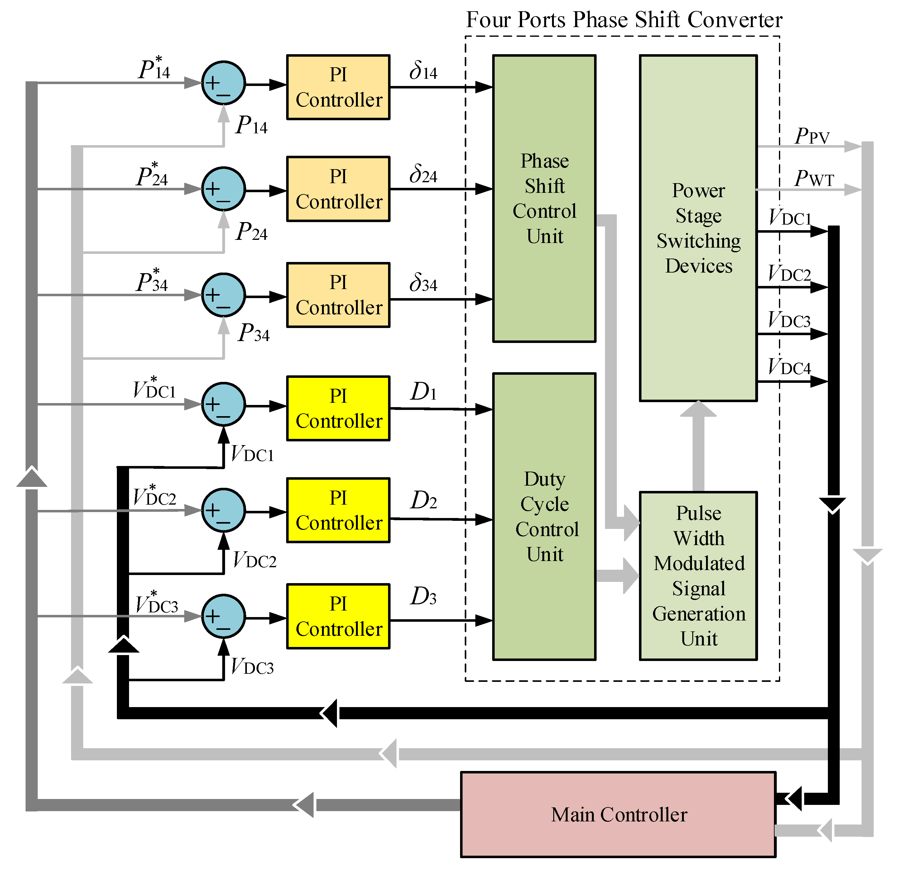
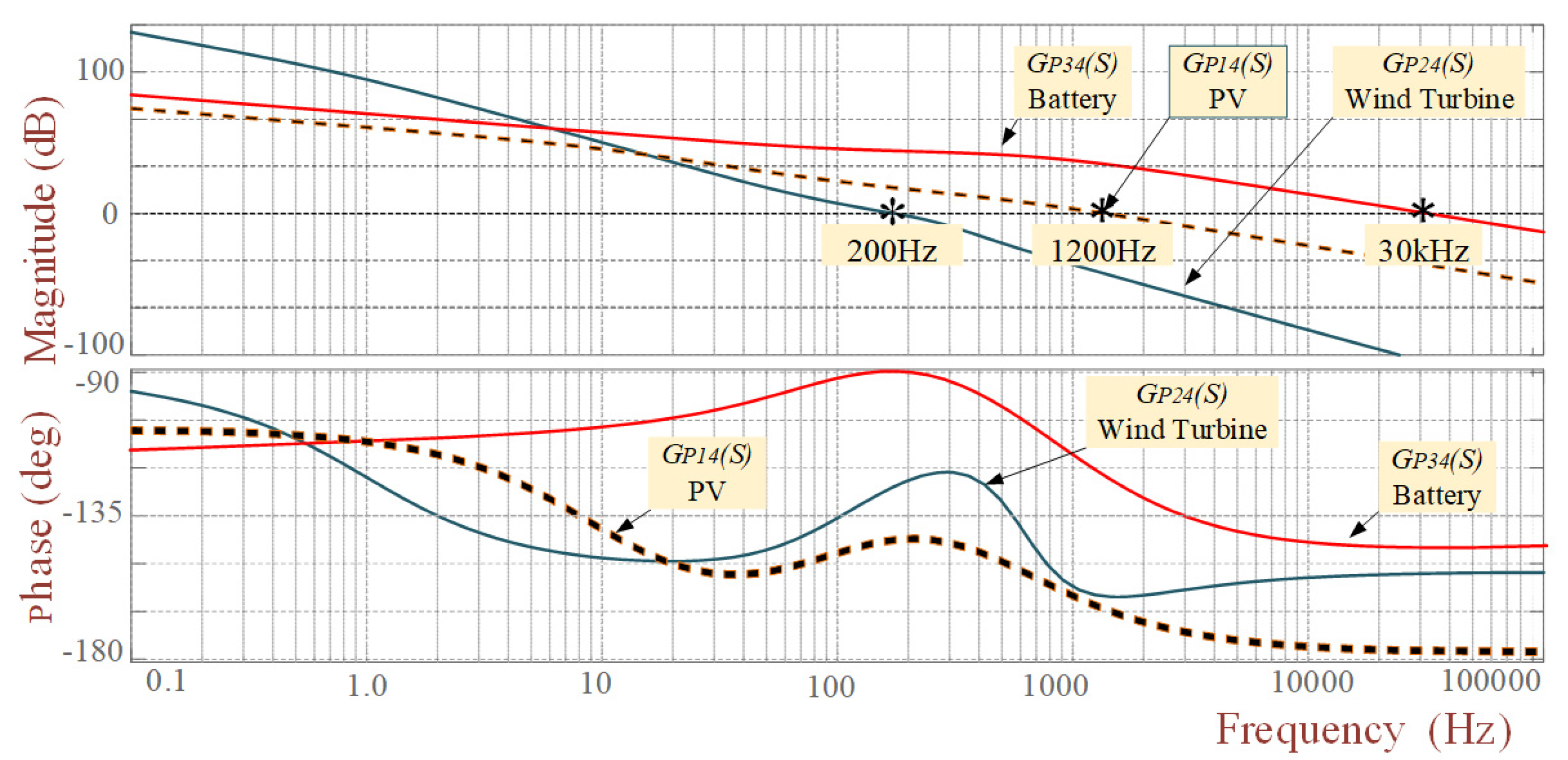
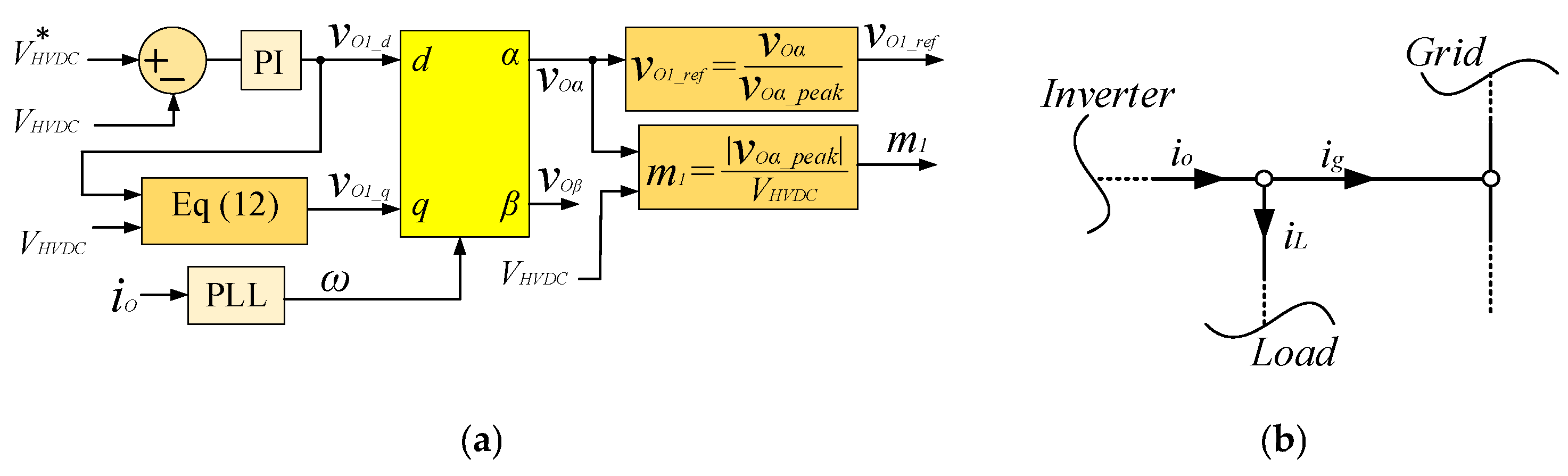
3. Analysis of Control System

The power flow equations in (2) and (3) show that the duty cycle and phase shift angle are the main elements that can be used as control variables. To discuss the control technique of the proposed converter, the simplified model of the phase shift converter facilitates the analysis.
A main issue related to the PV and wind turbine generator as renewable energy sources is the inherent intermittency and uncertainty in their energy generation. Therefore, the generated electrical energy is variable, and there is not a constant operation point to set the converter ports. As a result, the converter operating point in the PV and wind turbine ports needs to be adjusted according to the maximum available energy at any time. The process is known as maximum power point tracking (MPPT) in the PV and wind turbine converter ports. On the other hand, the extracted electrical power from the renewable energy sources should be controlled constantly, and follows the load demand and the grid conditions and standards. In this paper, to realize the MPPT, the duty cycle of the switching devices in the H-bridge converters has been used as the control variable. On the other hand, the phase shift angle between the generated AC voltages at the converter ports is used to control the power flow between the converter ports. Therefore, the duty cycle control system should be designed to operate independently of the phase shift controller. In theory, arbitrary power flow in the system can be realized by a unique set of phase shifts [16]. In the system proposed in this paper, there are multiple control objectives. The power flow control scheme aims to control the power flow between the ports while regulating the DC bus voltage of the port. Figure 4 illustrates the designed control system containing the control variables, reference signals provided by the master controller, and the control loops. The proportional integral (PI) controllers have been used in the control loops to regulate the DC voltage and realize the MPPT operation. The PI controller transfer function is presented as
G C ( S ) = K p + K i S
where Kp and Ki are the proportional and integral control coefficients, and in this paper are set as 0.01 and 0.56, respectively. The power flow control in each converter port can be designed to regulate the voltage according to the provided reference signal. As voltage-type energy sources like wind turbine and PVs have a variable operating voltage, a power control strategy can be used as an equivalent to current control, due to the slow change of the operating voltage of the source compared to the control bandwidth [16], and the dynamics of the power control loop is mainly determined by the port current. Therefore, the dynamics of the voltage control loop can be ignored in the control design process, and it is regarded as a relatively constant value, represented by a gain in the control loop. Following this strategy, the power flow between the ports can be controlled by a proper selection of the phase shifts of the high-frequency voltages linked to the transformer windings. To reduce the control conflicts between the two variables (duty cycle and the phase shift), the dynamic response of the power flow control loop is designed to operate faster than the voltage control loop by designing proper controllers, and adjusting kp and ki. The proportional and integral control coefficients are determined based on the required crossover frequency (ωc) and the phase margin (φm) of the voltage and power control loops [17,19,28]. Considering the PI controller transfer function as
C ( j ω ) = K P + K I j ω = K P j K I ω | C ( j ω ) | θ = | C ( j ω ) | [ ( cos ( θ ) + j sin ( θ ) ]
then the design problem is to find KP and KI for a chosen crossover frequency (ωc) and phase margin (φm), such that
C ( j ω c ) G ( j ω c ) = 1 ( 180 + ϕ m )
From (7), we can find the following equations
| C ( j ω c ) | = 1 | G ( j ω c ) | ,   C ( j ω c ) = θ = 180 + ϕ m G ( j ω c )  
Finally, from (6) and (8), the values of controller coefficient can be determined as [19]:
K P = | C ( j ω c ) | cos ( θ ) = cos ( θ ) | G ( j ω c ) | K I ω c = | C ( j ω c ) | sin ( θ ) = 1 | G ( j ω c ) | sin ( θ )
K I = ω c sin ( θ ) | G ( j ω c ) |
θ = 180 + ϕ m G ( j ω c )
and G(c) is the open-loop transfer function of the voltage or power control loops. On the other hand, to reduce the conflict between the control loops in different converter ports, the dynamic responses of the power control loops have been designed to operate in different speeds according to the nature and characteristics of the connected source, as presented in Figure 5. As can be seen, the crossing frequency of the wind turbine control loop is about 200 Hz as the slowest source, the PV equals 1.2 kHz, and the battery has 30 kHz as the fastest source. The duty cycle control loops have bandwidths less than 30 Hz for all three converter ports.
At the inverter side, the control section should be designed to provide proper values of the active and reactive power to the utility grid. Figure 6a shows the control system designed for the grid-connected inverter. By using this control system, the inverter output current compensates for the leading or lagging current of the load (reactive element of the load power) to have a unity power factor at the grid connected point. This is possible in reference to the current reference, presented in Figure 6b, which shows that the grid current basically depends on the load and inverter currents (ig = ioiL). To control the output voltage of the inverter, the grid voltage is transformed into the equivalent direct-quadrature (d-q) synchronous reference frame, with respect to the required output current angular speed. Therefore, the voltage elements aligned with the d-axis and q-axis determine the active and the reactive power injected by the inverter, respectively. The active power in is almost equal to the power generated by the input sources, or that received from the battery. Therefore, to control the active power extracted from the sources, the difference between the DC high-voltage at the inverter input (VHVS) and the reference value (V*HVS) is translated to the d component of the output voltage, as presented in Figure 6a. On the other hand, the reactive power is determined continuously by the instant value of the active power, considering the maximum available capacity of the inverter (determined based on output filter capacitors). The reason is that increasing reactive power may lead to an overmodulation and distortion of the output current due to the constant value of VHVS. Therefore, the available reactive component of the output voltage ( V O q * ) is determined from
V O q * = V H V S 2 V O d 2
where V O d is the d component of the output voltage. The energy management in the system uses the recorded data from previous operation times, the real-time values of the system parameters, including voltage and current, and energy cost as the main factors to determine the best operation scenario for the system, as illustrated in Figure 7 in brief. So, the operation scenarios and power flow directions in each scenario are selected to satisfy the objective function in the best way. Details of the energy management are beyond the scope of this paper, and will be covered in future reports.

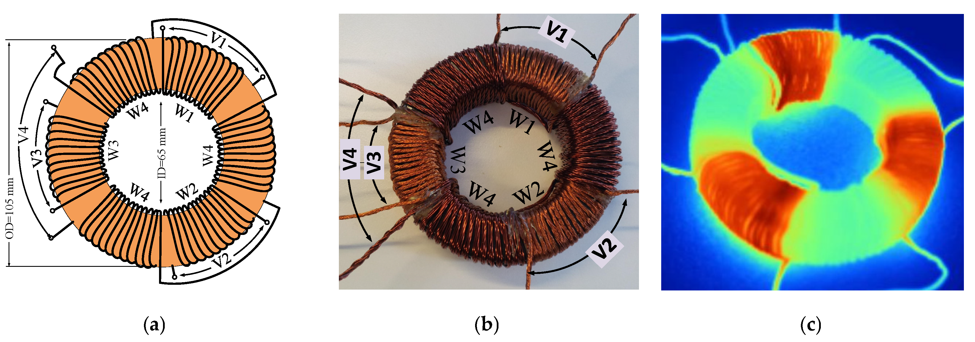
4. High-Frequency Transformer Design

As discussed in the previous sections, the multi-window high-frequency transformer plays an important role in the system performance and needs to be designed precisely. For the magnetic core, a toroidal core made from amorphous alloy 2605SA1 has been selected in this paper. To find the proper dimensions of the transformer, reluctance network modeling (RNM) is used for field analysis, as is explained in [18,21,24]. As a result, the number of turns for the windings and the core dimension were determined based on the required inductances, considering maximum flux density in the core. Figure 8 shows the dimension of the designed and experimentally developed transformer using Amorphous materials. The Litz wires have been used to reduce the skin and proximity effects due to the high-frequency currents. As illustrated in the figure, winding four (W4) is divided into three sections distributed around the magnetic core symmetrically. The windings linked to the PV panels, wind turbine and the battery, known as W1, W2 and W3, have a similar number of turns, winding length and physical situation, with respect to W4. The designed transformer was then tested for thermal limits as presented in Figure 8, considering the thermal limits with the maximum temperature rise of ∆T = 40 °C and with an ambient temperature (Tamb = 30 °C).

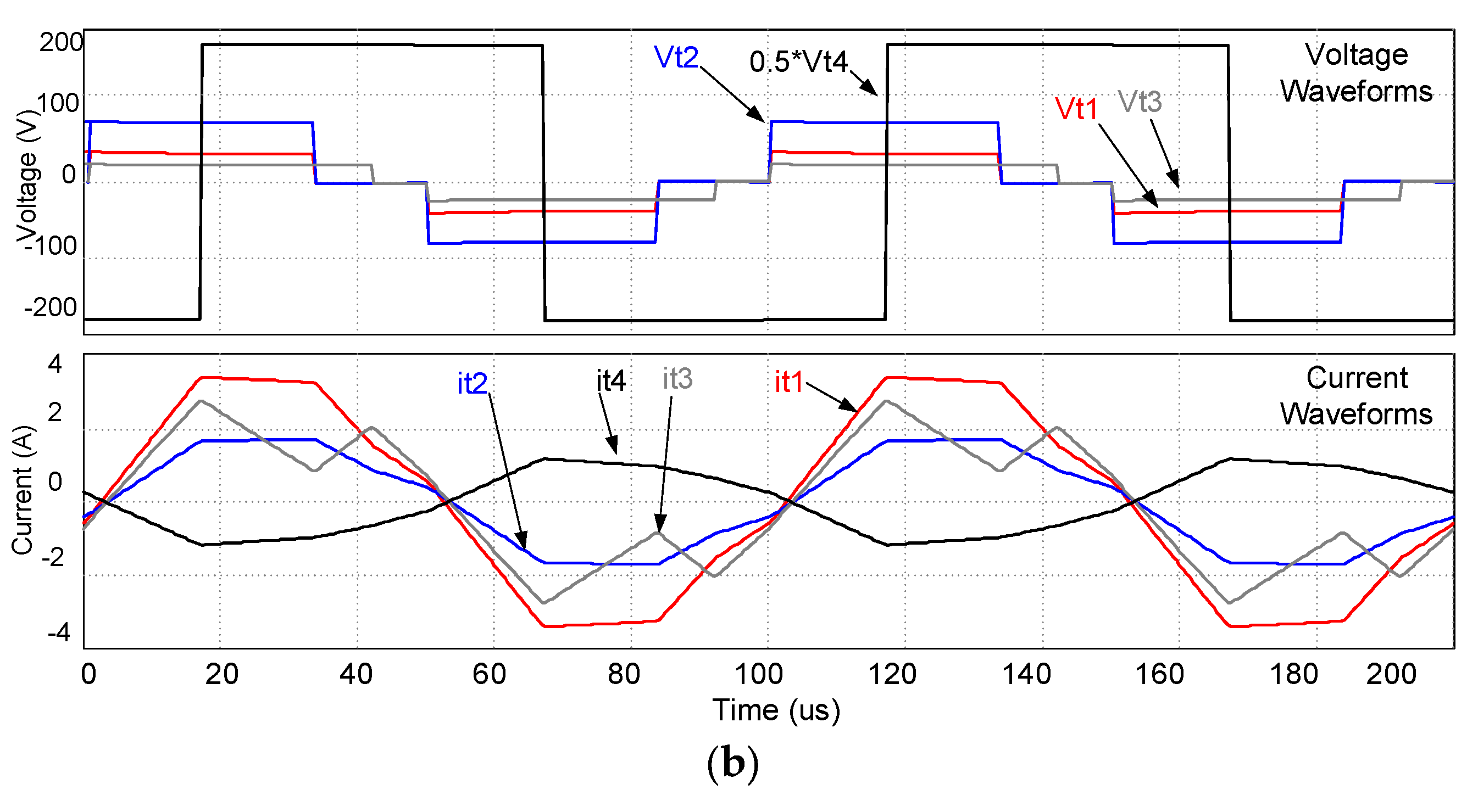
5. Numerical Simulations

The proposed system has been simulated using PSIM, and the proposed control technique is implemented to control the power flow between the ports. The system can operate in different operation modes, and the power can flow between the converter ports in different ways. A proper selection of the operation modes during a time frame is known as an energy management scenario, and different energy management scenarios, considering various effective factors, have been presented in the literature [17,25]. This paper is mainly focused on the operation principle and control technique of the proposed system, and the energy management discussion is out of the scope of this paper, and will be presented in detail in future publications. To provide a better understanding of the converter operation, some of the simulated waveforms of voltages and currents in the converter and grid-connected inverter have been presented and studied in this section. The system parameters that have been selected in the numerical simulation are illustrated in Table 1. The waveforms of the voltage and current of each converter port have been presented in Figure 9 for two different cases of the phase shift angles and duty cycles. As can be seen, the high-frequency voltage generated in the inverter port is not duty cycle controlled, but the waveforms in the PV (Vt1), wind turbine (Vt2) and the battery (Vt3) ports are duty cycle controlled. The power is transferred from the PV, wind turbine and the battery to the inverter port. The currents in the windings of the transformer have also been presented. In the second case, the power flows from the PV and wind turbine ports to the battery and inverter ports at the same time. As can be seen, the voltage in the PV and wind turbine ports is leading, compared to that of the battery and inverter. The duty cycle of the voltage in the battery port is different compared to the previous case. Figure 10 shows the inverter output waveform. The main objective for the inverter is to supply the load, and possibly the grid, from the renewable energy sources, or transfer the energy in the reverse direction from the grid to the battery, in order to charge the battery when is required. However, any energy transfer to/from the grid should be under the unity power factor, as the main condition for the grid-connected residential renewable energy systems. Therefore, the inverter output is controlled to provide the required output current with a proper phase shift angle, to satisfy the mandatory conditions. This was already discussed in the controller design section.
As presented in Figure 10a, the inverter is supplying the load and the grid. As the load current is slightly lagging behind the voltage, the inverter output is compensating the difference to force the grid current toward a unity power factor, as ig = ioiL, considering io as the inverter output current, iL as the load current and ig as the current injected into the utility grid. In the second case, as presented in Figure 10b, the power flows in the opposite direction from the grid to the load and inverter (charging the battery). In this case, the inverter is operating as a rectifier in the reverse direction, and the received current is adjusted properly to compensate for the slight phase shift in the load current due to the inductive load effect.
To study the dynamic response of the power flow control, two different cases of power flow control have been presented in Figure 11. As can be seen, in the first case, the response of the system to a step change in the load, while the output power is extracted from the PV and the wind turbine, is almost constant. The difference between the load demand and the renewable power is compensated for by the battery. However, it can also be supplied by the utility grid, depending on the availability of the battery energy and the cost of the grid energy compared to the battery at the presented time. The load demand variation is simulated by adding/removing a resistor in parallel with the output filter capacitor. In the second case, the load is supplied by the battery, grid and the wind turbine. When the load demand is increased, the demand is covered by the grid at the first stage. However, after a transient time, the battery port is activated to undertake the demand supply, and therefore the grid power is reduced to the previous value. The command for changing the operation condition is normally provided by the main control energy management section, and the details of energy management will be provided in the future publications.

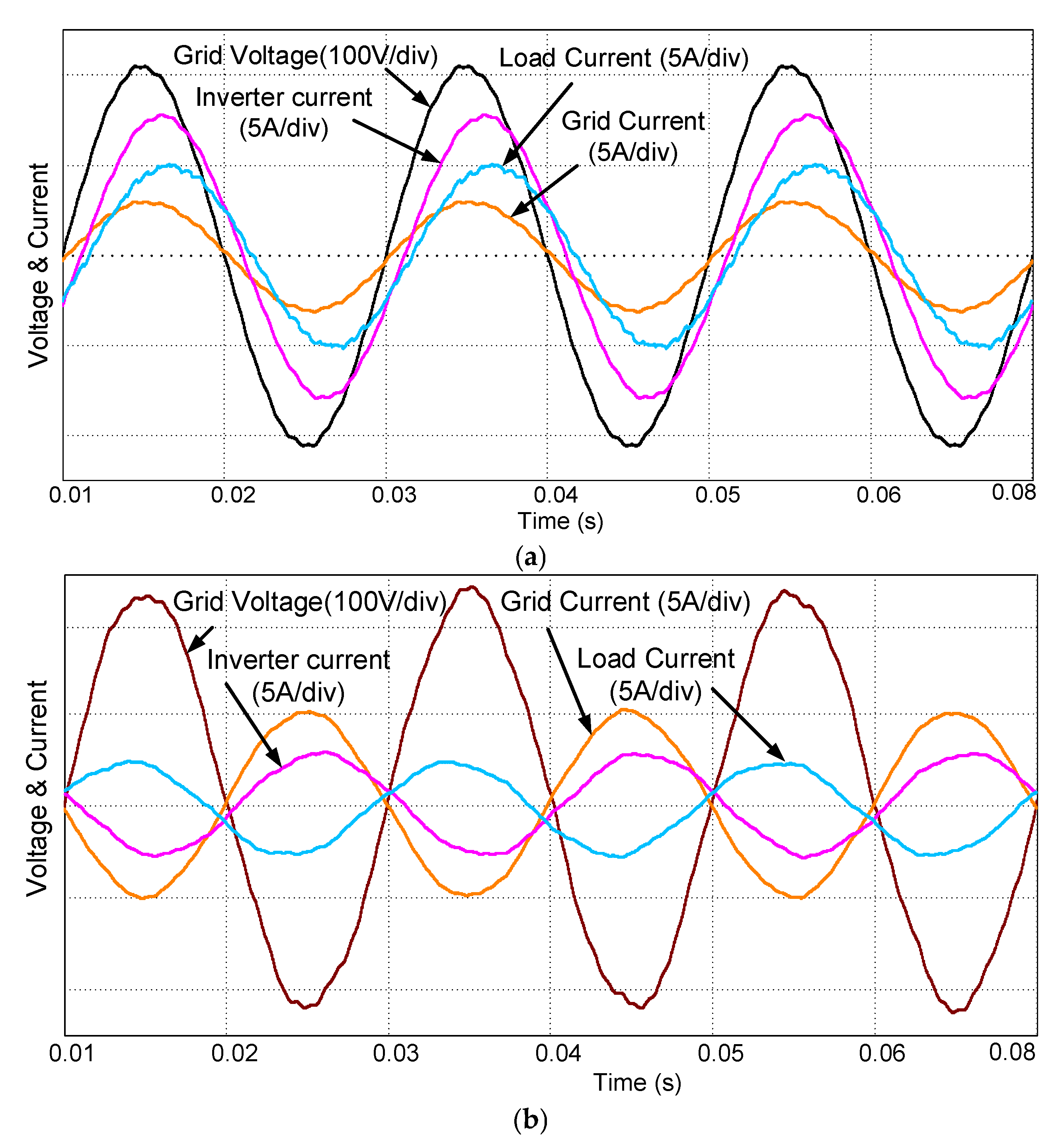
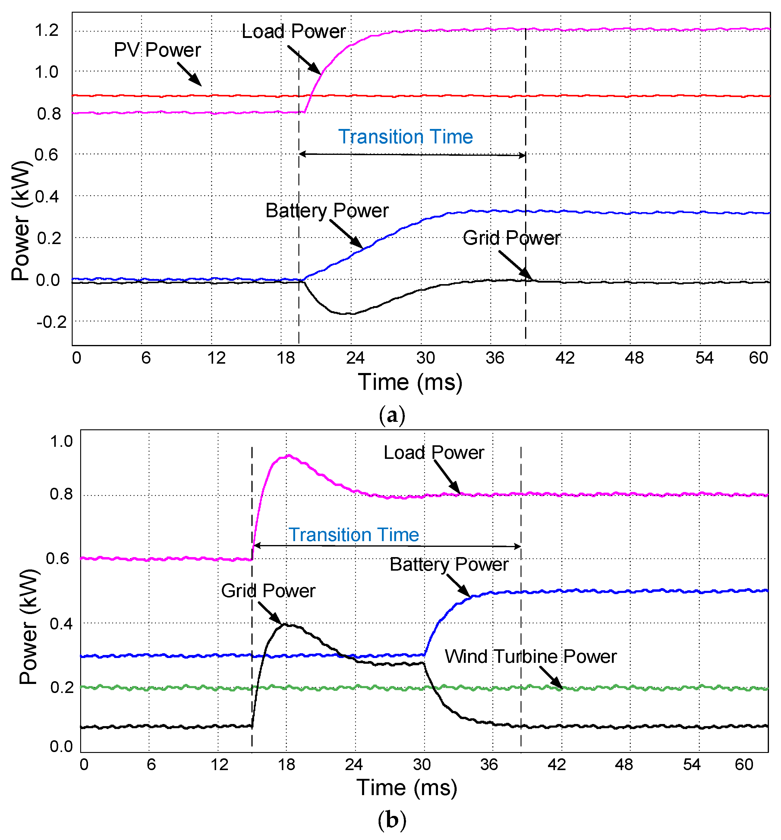
6. Experimental Tests

To validate the designed converter, a prototype of the proposed converter was developed in the lab as can be seen in the Figure 12. Two DSP controllers (C2000/TMS320F28335) made by Texas Instrument are used as local controllers to control the multi-port phase shift DC-DC converter and the single-phase inverter. A laptop (Asus, FK003QM, CPU: Intel-core i7, 2.6GHz, 12GB RAM) has been used as the master or global controller for energy management and data record and analysis. The Hall effect voltage (LV 25-P) and current (LTSR25-NP) sensors are used to measure the voltage and currents. The voltage and current of a bridge converter linked to the PV panel and the transformer voltage and current have been presented in Figure 13. As can be seen in Figure 13a, the interleaved inductors currents are almost the same, and the frequency ripple in the total PV current is twice the inductor currents. Figure 13b shows the voltage and current of the transformer winding in the PV linked port. The output voltage and currents of the single-phase inverter in different active and reactive power conditions is presented in the following figures. As can be seen in Figure 14a, the reactive power has been changed from 1.5 kVAR to 2.25 kVAR, and is of inductive type. However, the active power remained almost constant during the step change. The control system presented an acceptable performance to follow the applied step change. In Figure 14b, the reactive power injected into the utility grid by the inverter has been changed from inductive (2.55 kVAR) to capacitive (2.54 kVAR), with an almost constant active power (≈0.12 kW). This shows the ability of the proposed converter in reactive power compensation, and the improvement of the utility grid parameters, such as voltage and frequency in a limited range. To show the power flow to/from the utility grid, the power flow from the inverter to the grid has been sharply changed to an opposite direction, from the grid to the converter, to charge the battery as illustrated in Figure 14c. In this case, the inverter is operated in the reverse direction as a rectifier, and the energy is transferred from the grid to the battery. This shows the ability of the proposed converter to be used as a virtual power plant and operate as an assistance to the utility grid, and also provides benefits for the consumer. As can be seen, the inverter is supplying 1.83 kW to the load and utility grid, and then the active power is changed to 1.73 kW in the reverse direction to charge the battery. The experimental test results show that the proposed system can be used successfully not only to supply the load, but also to improve the utility grid performance.

7. Conclusions

A multiport converter topology for integrating a PV system, a wind turbine generator and a battery is presented in the paper to supply a grid-connected domestic load. Using a multi-winding transformer, we isolated the converter ports and improved the system safety, matched the voltage levels of the converter ports, and provided a simple power flow path between the converter ports. The operation principle and control technique of the proposed system are presented in detail. It was seen that the proposed control system and the topology are able to operate in the four quadrant mode by providing inductive and capacitive reactive power to the grid. To validate the system topology and control technique, numerical simulations have been performed using PSIM software. The waveforms of the voltage and currents of a single H-bridge unit in the multi-port converter, the single-phase inverter and the dynamic response of the system under a step change in the load, have been presented and analyzed. To validate the designed converter and the control system, experimental tests were conducted using a laboratory set prototype.

Author Contributions

Conceptualization, M.J.; methodology, M.J.; software, Z.M.; validation, Z.M.; formal analysis, M.J.; investigation, M.J.; resources, Z.M.; data curation, Z.M.; writing—original draft preparation, M.J.; writing—review and editing, M.J. and, Z.M.; visualization, Z.M.; supervision, M.J.; project administration, M.J.; funding acquisition, M.J. All authors have read and agreed to the published version of the manuscript.

Funding

This research received no external funding.

Conflicts of Interest

The authors confirm that there is not any conflict of interest related to this manuscript.

Nomenclature

DABDual Active BridgeδijPhase shift angle port i to j
DSPDigital Signal ProcessorfsSwitching frequency
PIProportional IntegralPijPower flow from port i to j
PVPhotovoltaicLijSummation of leakage inductances of windings in ports i and j
MPPTMaximum Power Point TrackingDiDuty cycle in port i
RNMReluctance Network ModelingKp, KiProportional and integral controller coefficients
UPSUninterruptible Power Supplyφm, GmPhase margin, gain margin

References

  1. Tao, H.; Duarte, J.L.; Hendrix, M. Three-port triple-half-bridge bidirectional converter with zero-voltage switching. IEEE Trans. Power Electron. 2008, 23, 782–792. [Google Scholar] [CrossRef]
  2. Jafari, M.; Malekjamshidi, Z.; Zhu, J. Design, analysis and control of a magnetically-coupled multi-port multi-operation-mode residential micro-grid. In Proceedings of the 2017 20th International Conference on Electrical Machines and Systems (ICEMS), Sydney, NSW, Australia, 11–14 August 2017; pp. 1–6. [Google Scholar] [CrossRef] [Green Version]
  3. Zhao, C.; Round, S.; Kolar, J.W. Buck and boost start-up operation of a three-port power supply for hybrid vehicle applications. In Proceedings of the IEEE 36th Conference on Power Electronics Specialists Conference, Recife, Brazil, 16 June 2005; pp. 1851–1857. [Google Scholar]
  4. Malekjamshidi, Z.; Jafari, M.; Imanieh, M. Implementation of a full bridge series-parallel resonant DC-DC converter using ANN and SSM controllers. In Proceedings of the 2011 IEEE National Aerospace and Electronics Conference (NAECON), Dayton, OH, USA, 20–22 July 2011; pp. 203–210. [Google Scholar]
  5. Jafari, M.; Malekjamshidi, Z.; Zhu, J.; Jafari, M. Design, simulation and implementation of an intelligent MPPT using a ZVCS resonant DCDC converter. In Proceedings of the 2012 IEEE International Conference on Power and Energy (PECon), Kota Kinabalu, Malaysia, 2–5 December 2012; pp. 280–285. [Google Scholar]
  6. Jafari, M.; Malekjamshidi, Z.; Islam, M.R.; Zhu, J. Comparison of singular and modular structures of multiport converters for residential applications in smart grids. In Proceedings of the 2014 IEEE Innovative Smart Grid Technologies-Asia (ISGT ASIA), Kuala Lumpur, Malaysia, 20–23 May 2014; pp. 606–611. [Google Scholar] [CrossRef]
  7. Jafari, M.; Malekjamshidi, Z. Design, Simulation and implementation of an adaptive controller on base of artificial neural networks for a resonant DC-DC converter. In Proceedings of the 2011 IEEE Ninth International Conference on Power Electronics and Drive Systems, Singapore, 5–8 December 2011; pp. 1043–1046. [Google Scholar] [CrossRef]
  8. Malekjamshidi, Z.; Jafari, M.; Islam, R.; Zhu, J. A comparative study on characteristics of major topologies of voltage source multilevel inverters. In Proceedings of the 2014 IEEE Innovative Smart Grid Technologies—Asia (ISGT ASIA), Kuala Lumpur, Malaysia, 20–23 May 2014; pp. 612–617. [Google Scholar] [CrossRef]
  9. Savitha, K.P.; Kanakasabapathy, P. Multi-port DC-DC converter for DC microgrid applications. In Proceedings of the 2016 IEEE 6th International Conference on Power Systems (ICPS), New Delhi, India, 4–6 March 2016; pp. 1–6. [Google Scholar] [CrossRef]
  10. Liu, Y.-C.; Chen, Y.-M. A systematic approach to synthesizing multi-input DC–DC converters. IEEE Trans. Power Electron. 2009, 24, 116–127. [Google Scholar] [CrossRef]
  11. Benavides, N.; Chapman, P. Power budgeting of a multiple-input buck-boost converter. IEEE Trans. Power Electron. 2005, 20, 1303–1309. [Google Scholar] [CrossRef]
  12. Jafari, M.; Hunter, G.; Zhu, J.; Jafari, M. A new topology of multi-input multi-output Buck-Boost DC-DC Converter for microgrid applications. In Proceedings of the 2012 IEEE International Conference on Power and Energy (PECon), Kota Kinabalu, Malaysia, 2–5 December 2012; pp. 286–291. [Google Scholar]
  13. Jafari, M.; Malekjamshidi, Z. Optimal energy management of a residential-based hybrid renewable energy system using rule-based real-time control and 2D dynamic programming optimization method. Renew. Energy 2020, 146, 254–266. [Google Scholar] [CrossRef]
  14. Duarte, J.L.; Hendrix, M.; Simões, M.G. Three-port bidirectional converter for hybrid fuel cell systems. IEEE Trans. Power Electron. 2007, 22, 480–487. [Google Scholar] [CrossRef] [Green Version]
  15. Tao, H.; Kotsopoulos, A.; Duarte, J.; Hendrix, M. Family of multiport bidirectional DC–DC converters. IEE Proc. Electr. Power Appl. 2006, 153, 451. [Google Scholar] [CrossRef] [Green Version]
  16. Tao, H. Integration of Sustainable Energy Sources through Power Electronic Converters in Small Distributed Electricity Generation Systems. Ph.D. Thesis, Technische Universiteit Eindhoven, Eindhoven, The Netherlands, 2008. [Google Scholar]
  17. Jafari, M.; Malekjamshidi, Z.; Zhu, J. Accurate copper loss analysis of a multi-winding high-frequency transformer for a magnetically-coupled residential micro-grid. In Proceedings of the 2017 20th International Conference on Electrical Machines and Systems (ICEMS), Sydney, NSW, Australia, 11–14 August 2017; pp. 1–6. [Google Scholar] [CrossRef] [Green Version]
  18. Jafari, M.; Malekjamshidi, Z.; Islam, R.; Zhu, J.; Mohammad, J. Modeling of magnetic flux in multi-winding toroidal core high frequency transformers using 3D reluctance network model. In Proceedings of the 2015 IEEE 11th International Conference on Power Electronics and Drive Systems, Sydney, NSW, Australia, 9–12 June 2015; pp. 413–418. [Google Scholar] [CrossRef]
  19. Jafari, M.; Malekjamshidi, Z.; Zhu, J.; Khooban, M.H. A novel predictive fuzzy logic-based energy management system for grid-connected and off-grid operation of residential smart microgrids. IEEE J. Emerg. Sel. Top. Power Electron. 2020, 8, 1391–1404. [Google Scholar] [CrossRef]
  20. Tao, H.; Kotsopoulos, A.; Duarte, J.L.; Hendrix, M.A.M. Transformer-coupled multiport ZVS bidirectional DC–DC converter with wide input range. IEEE Trans. Power Electron. 2008, 23, 771–781. [Google Scholar] [CrossRef] [Green Version]
  21. Jafari, M.; Malekjamshidi, Z.; Zhu, J. Copper loss analysis of a multiwinding high-frequency transformer for a magnetically-coupled residential microgrid. IEEE Trans. Ind. Appl. 2018, 55, 283–297. [Google Scholar] [CrossRef]
  22. Jafari, M.; Malekjamshidi, Z.; Zhu, J. A magnetically coupled multi-port, multi-operation-mode micro-grid with a predictive dynamic programming-based energy management for residential applications. Int. J. Electr. Power Energy Syst. 2019, 104, 784–796. [Google Scholar] [CrossRef]
  23. Jafari, M.; Malekjamshidi, Z.; Lei, G.; Wang, T.; Platt, G.; Zhu, J. Design and implementation of an amorphous high-frequency transformer coupling multiple converters in a smart Microgrid. IEEE Trans. Ind. Electron. 2016, 64, 1028–1037. [Google Scholar] [CrossRef] [Green Version]
  24. Jafari, M.; Malekjamshidi, Z.; Zhu, J. Design and development of a multi-winding high-frequency magnetic link for grid integration of residential renewable energy systems. Appl. Energy 2019, 242, 1209–1225. [Google Scholar] [CrossRef]
  25. Chen, Y.-M.; Liu, Y.-C.; Wu, F.-Y. Multi-input DC/DC converter based on the multiwinding transformer for renewable energy applications. IEEE Trans. Ind. Appl. 2002, 38, 1096–1104. [Google Scholar] [CrossRef]
  26. Michon, M.; Duarte, J.; Hendrix, M.; Simoes, M. A three-port bi-directional converter for hybrid fuel cell systems. In Proceedings of the 2004 IEEE 35th Annual Power Electronics Specialists Conference, Aachen, Germany, 20–25 June 2004; pp. 4736–4742. [Google Scholar] [CrossRef]
  27. Zhao, C.; Kolar, J. A novel three-phase three-port UPS employing a single high-frequency isolation transformer. In Proceedings of the 2004 IEEE 35th Annual Power Electronics Specialists Conference, Aachen, Germany, 20–25 June 2004; pp. 4135–4141. [Google Scholar] [CrossRef]
  28. Jafari, M.; Malekjamshidi, Z.; Lu, D.D.C.; Zhu, J. Development of a fuzzy-logic-based energy management system for a multiport multioperation mode residential smart microgrid. IEEE Trans. Power Electron. 2018, 34, 3283–3301. [Google Scholar] [CrossRef]
  29. Jafari, M.; Platt, G.; Malekjamshidi, Z.; Zhu, J. Technical issues of sizing Lead-Acid batteries for application in residential renewable energy systems. In Proceedings of the 2015 4th International Conference on Electric Power and Energy Conversion Systems (EPECS), Sharjah, UAE, 24–26 November 2015; pp. 1–6. [Google Scholar] [CrossRef]
  30. Liu, D.; Li, H. A ZVS Bi-directional DC–DC converter for multiple energy storage elements. IEEE Trans. Power Electron. 2006, 21, 1513–1517. [Google Scholar] [CrossRef]
  31. Jafari, M.; Malekjamshidi, Z.; Li, L.; Zhu, J.; Jafari, M. Performance analysis of full bridge, boost half bridge and half bridge topologies for application in phase shift converters. In Proceedings of the 2013 International Conference on Electrical Machines and Systems (ICEMS), Busan, Korea, 26–29 October 2013; pp. 1589–1595. [Google Scholar]
  32. Jafari, M.; Malekjamshidi, Z.; Platt, G.; Zhu, J.; Dorrell, D.G. A multi-port converter based renewable energy system for residential consumers of smart grid. In Proceedings of the IECON 2015—41st Annual Conference of the IEEE Industrial Electronics Society, Yokohama, Japan, 9–12 November 2015; pp. 5168–5173. [Google Scholar] [CrossRef]
  33. Shi, Y.; Li, R.; Xue, Y.; Li, H. High-frequency-link based grid-tied PV system with small DC-link capacitor and low-frequency ripple-free maximum power point tracking. IEEE Trans. Power Electron. 2015, 31, 1. [Google Scholar] [CrossRef]
  34. Chen, G.; Xu, D.; Wang, Y.; Lee, Y.-S. A new family of soft-switching phase-shift bidirectional DC-DC converters. In Proceedings of the 2001 IEEE 32nd Annual Power Electronics Specialists Conference, Vancouver, BC, Canada, 12–21 June 2002; pp. 859–865. [Google Scholar]
  35. Jafari, M.; Islam, R.; Malekjamshidi, Z.; Zhu, J. Modeling of multi-winding high-frequency transformers as a common magnetic-link in smart micro-grids. In Proceedings of the 2015 International Conference on Electrical & Electronic Engineering (ICEEE), Rajshahi, Bangladesh, 4–6 November 2015; pp. 249–252. [Google Scholar] [CrossRef]
  36. Kheraluwala, M.H.; Gascoigne, R.W.; Divan, D.M.; Baumann, E.D. Performance characterization of a high-power dual active bridge DC-to-DC converter. IEEE Trans. Ind. Appl. 1992, 28, 1294–1301. [Google Scholar] [CrossRef]
  37. Vangen, K.; Melaa, T.; Bergsmark, S.; Nilsén, R. Efficient high-frequency soft-switched power converter with signal processor control. In Proceedings of the Thirteenth International Telecommunications Energy Conference—INTELEC 91, Kyoto, Japan, 5–8 November 1991; pp. 631–639. [Google Scholar]
  38. Vangen, K.; Melaa, T.; Adnanes, A. Soft-switched high-frequency, high power DC/AC converter with IGBT. In Proceedings of the PESC’92 Record. 23rd Annual IEEE Power Electronics Specialists Conference, Toledo, Spain, 29 June–3 July 1992; pp. 26–33. [Google Scholar]
  39. Vangen, K.; Melaa, T.; Adnanes, A.K.; Kristiansen, P.E. Dual active bridge converter with large soft-switching range. In Proceedings of the Fifth European Conference on Power Electronics and Applications (EPE’93), Brighton, UK, 13–16 September 1993; pp. 328–333. [Google Scholar] [CrossRef]
  40. Zhang, J.; Xu, D.M.; Qian, Z. An improved dual active bridge DC/DC converter. In Proceedings of the 2001 IEEE 32nd Annual Power Electronics Specialists Conference, Vancouver, BC, Canada, 17–21 June 2001; pp. 232–236. [Google Scholar] [CrossRef]
  41. Zhang, J.; Zhang, F.; Xie, X.; Jiao, D.; Qian, Z. A novel ZVS DC/DC converter for high power applications. IEEE Trans. Power Electron. 2004, 19, 420–429. [Google Scholar] [CrossRef]
  42. Jafari, M.; Malekjamshidi, Z.; Zhu, J.; Mohammad, J. Analysis of operation modes and limitations of dual active bridge phase shift converter. In Proceedings of the 2015 IEEE 11th International Conference on Power Electronics and Drive Systems, Sydney, NSW, Australia, 9–12 June 2015; pp. 393–398. [Google Scholar]
Figure 1. Topology of the proposed hybrid renewable energy system, including the multi-port phase shift converter and grid-connected inverter.
Inventions 05 00031 g001
Figure 2. Simplified model of the four-port converter by simplifying the multi-winding transformer using cantilever model.
Inventions 05 00031 g002
Figure 3. The waveforms of voltage and current of port one and four in the transformer winding for three cases wherein (a) v1 is lagging v4, (b) v1 and v2 are in phase and (c) v1 is leading v2, where duty cycle of v1 (D1) and phase shift angle are presented.
Inventions 05 00031 g003
Figure 4. The control system for multi-port converter in the proposed system.
Inventions 05 00031 g004
Figure 5. The magnitude and phase Bode diagrams of the power control closed loop transfer functions.
Inventions 05 00031 g005
Figure 6. (a) The control system for the grid-connected inverter and (b) current direction reference in the inverter output.
Inventions 05 00031 g006
Figure 7. Energy management block diagram in brief.
Inventions 05 00031 g007
Figure 8. (a) Dimension of designed transformer, (b) the experimentally developed transformer and (c), the transformer under the thermal test using thermal camera.
Inventions 05 00031 g008
Figure 9. The waveforms of the voltage and current in the multi-winding transformer (a) for δ14 = π/2, δ24 = π/2, δ34 = π/2, D1 = 0.6, D2 = 0.6, D3 = 0.4, δ14 = π/2 and (b) δ14 = π/2, δ24 = π/2, δ34 = π/2, D1 = 0.6, D2 = 0.6, D3 = 0.8.
Inventions 05 00031 g009aInventions 05 00031 g009b
Figure 10. The inverter output, load and the grid currents (a) when power is transferred from the inverter to the grid and the load, and (b) when inverter is operating as rectifier and power is transferred in the opposite direction, from grid to the load and battery, reduced back to the previous value.
Inventions 05 00031 g010
Figure 11. Step response in the load demand and operation of the proposed system in compensation of load demand (a) when the load demand is compensated for by the battery during transition time, and (b) when the load demand is compensated for by the utility grid during the transition time.
Inventions 05 00031 g011
Figure 12. The experimentally developed multi-port converter.
Inventions 05 00031 g012
Figure 13. (a) the current in the interleaved boost converter and the PV output current and (b), the current and voltage waveforms in winding one and two of the transformer.
Inventions 05 00031 g013
Figure 14. The experimental test results for power flow control, (a) the reactive power has been changed from 1.5 kVAR to 2.25 kVAR and is of inductive type, (b) the reactive power injected into the utility grid by the inverter has been changed from inductive (2.55 kVAR) to capacitive (2.54 kVAR), and (c) the inverter is supplying 1.83 kW to the load and utility grid, and then the active power is changed to 1.73 kW in the reverse direction to charge the battery.
Inventions 05 00031 g014
Table 1. System parameters for numerical simulations.
ParametersValuesParametersValues
Leakage inductance of transformer windingsL1 = 0.012 mH, L2 = 0.01 mH, L3 = 0.008 mH,
L4 = 0.02 mH
Switching frequency of multi-port converterfsc = 15 kHz
Number of turns of each winding of the transformerN1 = 18, N2 = 18, N3 = 18, N4 = 54DC bus voltageV1 = 110 V, V2 = 110 V, V3 = 110 V,
V4 = 300 V
Magnetizing inductance LmLm = 1.12 mHSwitching frequency of Inverterfsi = 10 kHz
Rated power in each input of the converter PPV = 800 W, PBT = 600 W
PWT = 800 W
Utility grid parametersf = 50 Hz,
V(rms) = 150 V
PV characteristics (Totally 4 Panels)Each panel: Vo = 35 V,
Imax = 6 A Pmax = 200 W
Wind turbine characteristicsV = 100 V DC, P = 800 W, Imax = 9 A

