Article

Heat Transfer and Thermal Management of Interior Permanent Magnet Synchronous Electric Motor

1
Department of Mechanical and Automation Engineering, Da-Yeh University, No. 168, University Road, Dacun Changhua 51591, Taiwan
2
Department of Electrical Engineering, National Cheng Kung University 70101, Tainan City, Taiwan
3
Department of System and Naval Mechatronic Engineering, National Cheng Kung University, No. 1, University Road, Tainan City 70101, Taiwan
4
Electronic Motor Technology Research Center, National Cheng Kung University, No. 1, University Road, Tainan City 70101, Taiwan
*
Author to whom correspondence should be addressed.
Inventions 2019, 4(4), 69; https://doi.org/10.3390/inventions4040069
Submission received: 7 November 2019 / Revised: 19 November 2019 / Accepted: 21 November 2019 / Published: 28 November 2019
(This article belongs to the Special Issue Heat transfer and Thermal Managements of Innovative Systems)

Abstract

:
Geometric complexities and multi-physical phenomena add difficulties for predicting the thermal field and hence thermal management of an electric motor. A numerical design model that combined electromagnetic and thermal-fluid analysis was proposed for disclosing the detailed temperature distributions of each component in an electric motor. The thermal fluid analysis implemented ANSYS-Fluent code to unravel the thermal field of the interior permanent magnet synchronous electric motor fitted with a smooth or novel spirally twisted channel in the cooling water jacket of a stator with and without shaft cooling. In accordance with the thermal powers converted from the various electromagnetic losses of the electric motor, the complex heat conduction model with realistic thermal boundary conditions was formulated. Initially, the turbulent flow structures and channel averaged Nusselt numbers of the spiral channels without and with the sectional twist were comparatively examined for acquiring the convective thermal boundary conditions in the water jacket. With the high thermal conductivity of the aluminum water jacket, the heat-transfer improvements from the smooth-spiral-channel conditions by using the twisted spiral channel were effective for reducing the average temperatures by about 10% but less effective for altering the characteristic thermal field in the water jacket. At 1290 < Dn < 6455 or 5000 < Re < 25,000 for the spiral channel flows, the channel average Nusselt numbers ratios between the smooth and twisted spiral channels were elevated to 1.18–1.09 but decreased with the increase of Dn or Re. A set of heat-transfer correlations for estimating the Nusselt numbers of Taylor flow in the rotor-to-stator air gap was newly devised from the data available in the literature. While the cooling effectiveness of the water jacket and shaft was boosted by the sectional twists along the spiral channel of the water jacket, the presence of Taylor flow in the annual air gap prohibited the effective rotor-to-stator heat transmission, leading to hot spots in the rotor. By way of airflow cooling through the rotating hollow shaft, the high temperatures in the rotor were considerably moderated. As the development of Taylor flow between the rotor and stator was inevitable, the development of active or passive rotor cooling schemes was necessary for extending the power density of an electric motor. Unlike the previous thermal circuit or lumped-parameter thermal model that predicted the overall temperatures of motor components, the present coupled electromagnetic and thermal-fluid model can reveal the detailed temperature distributions in an electric motor to probe the local hot spots of each component in order to avoid overheating at the early design stage.

1. Introduction

A permanent magnet electric motor is popular as the prime mover of the powertrain for an electric vehicle. With such powertrain applications, the high torque output necessitated high current density with the accompanying temperature rises. In particular, the demagnetization of the magnets attributed to the thermal impacts [1,2] considerably undermined the motor performances. An adequate cooling scheme is essential to ensure the efficiency and power density of a permanent magnet electric motor. The thermal sources in an electric motor were mainly converted from the power losses generated by the active components such as the electromagnetic loss, the core power loss, the permanent magnet power loss and the mechanical loss [3]. Depending on the comparative significances of these various types of power loss and the operation condition, the single or hybrid motor cooling schemes were deployed accordingly. In addition to the endurance of the electromagnetic performance assured by the cooling scheme, the robust cooling configurations with low manufacturing complexity and operating cost were preferable for meeting the thermal characteristics requested by an electric motor with the demands for minimization, large torque and high power density.
The current cooling technologies for the automotive traction motors, including the natural convection, the forced convection and the phase-change cooling methods, were comparatively reviewed with the key factors for heat-transfer improvements as well as the pros and cons of each cooling method discussed [4]. The heat flux generated by an electric motor was transferred to the free and/or the forced convective coolant flows via the various internal heat-transfer pathways in the motor. As the thermal conductivity of the laminated agent for the winding coils was extremely low, the associated high conductive thermal resistances considerably undermined the effectiveness of the motor cooling system. While it remains a difficult task to evaluate the effective thermal conductivity of the compound copper coils in the laminations, several previous attempts reviewed in [4] treated the laminated coils as a homogeneous material with an effective thermal conductivity. The present study proposed a simple model to disclose the non-homogeneous heat conduction properties of the laminated coils which will be illustrated later. Nevertheless, with low power density and small torque output, the free convective fins were usually deployed around motor casing. A common practice to enhance the cooling effectiveness of a free convective cooling scheme was the extension of fin area that simultaneously increased the airflow resistance to offset the gaining factor. In [5], the semi-empirical method was proposed to optimize the cooling effectiveness of such fin-flow by appropriately selecting the fin height-to-pitch ratios at different Grashof numbers and tilted angles of fins. To cope with the high power density, the forced convective cooling scheme was employed at the expense of external power consumption. In this respect, the thermal performances for the air-cooled [6,7,8,9,10,11,12,13,14], water-cooled [15,16,17] and oil-cooled [18] electric motors were numerically and, or, experimentally studied. In addition to the relative low cooling capacity of the forced convective airflow, the emission of acoustic noise from the fan was a major problem. Several attempts for mitigating the fan noise, especially at high speeds, were proposed by using the forward-swept blades [19], the aero-foil shaped blades [20], the bell-mouth fan entry, the irregular-pitch-blade fan and/or reducing the blade number [21]. With the forced convective liquid cooling schemes, the housing jackets embedded with a variety of coolant channels were commonly adopted. But the jacket cooling was generally less effective for cooling the end regions. The heat sources generated in an electric motor were transferred through the various types of internal thermal resistances to the liquid flow in the jacket. Thus, the convective coolant flow characteristics, the geometric and material properties that formulated the internal conductive thermal resistances, as well as the Taylor vortices developed in the annual air gap between the stator and the rotating rotor, were influential to the thermal field of an electrical motor. To reduce the conductive thermal resistance of a housing jacket, the forced convective coolant passages were directly machined into the stator laminations at the stator yoke [22] or the winding slots [23,24]; whilst the prevention of the coolant passages from interfering with the magnetic flux was also required [4].
Recently, electric motor cooling research utilized the phase change activities that facilitated the internal and, or, the external heat transmissions [25,26,27,28,29] with extremely high effective thermal conductivities and no pumping power consumption. In [25], eight pair of L-shaped heat pipes were installed to transfer the heat flux emitted from the rotor to the stator coolant circuit [25]. With the combined stator water (air) cooling scheme and the L-shaped heat pipes, the casing temperature of the electric motor was reduced to 68.4 °C from 102.2 °C at the thermal load of 150 W [25]. For transmitting the heat flux generated by the magnets of the rotor to the shaft, the rotating closed-loop heat pipes and thermosiphons [28,29] were fabricated into the pad shape to take the advantages of centrifugal forces that assisted the vapor-liquid circulations. The boiling number, centrifuge and condenser thermal resistance were influential for the overall thermal resistances of such rotating pads [28,29]. Another form of phase-change cooling method for electric motor cooling utilized liquid sprays to cool the end coil-turns of stator and rotor and/or the rotor [30]. The evaporation of coolant upon impingement transferred the heat flux at very high rate without reducing magnetic field fluctuation or creating electric noise; but suffered from high pressure drops across the nozzles [31]. The review for the mechanisms of heat generation due to the various losses in an electric motor and the corresponding cooling solutions [32] concluded that the increased thermal conductivity of the lamination agent in rotor and stator was effective for boosting the overall cooling performance. The integration of spray, air and liquid cooling units, along with the materials with high thermal emissivity further enhanced the cooling effectiveness [32].
Along with the cooling technology development [4,5,6,7,8,9,10,11,12,13,14,15,16,17,18,19,20,21,22,23,24,25,26,27,28,29,30,31,32], the optimal thermal managements at the component and powertrain levels were simultaneously pursued [33,34,35,36,37,38,39,40]. The early attempts in this respect adopted the lumped-parameter thermal models that simplified the components into discrete units of thermal resistor, thermal capacitor and heat sources in the emulated thermal circuits [33,34,35]. But the permissibility for such lumped assumptions was not universal; and the appropriate thermal parameters for the associated motor configurations and their responses to the variations in cooling conditions were difficult to identify using the lumped-parameter thermal models [36]. The advancement in this field has been directed toward the electromagnetic-thermal coupled analysis [37,38,39] that started from an electromagnetic simulation to disclose the torque, losses, flux linkage and density as well as field intensity at the predefined motor power, structure and speed. The electromagnetic losses were converted into the various thermal resistor, capacitor and sources in the thermal network for estimating the temperatures of the components. A variety of iterative schemes were developed to cope with the temperature-dependent material properties which were influential to the electromagnetic-thermal analysis. The simplified model aimed at estimating the temperature rise in the components of the permanent magnetic motors considered the losses in the thermal circuit with the aid of finite element simulation to unravel the potential demagnetizing of the magnets due to the additional losses generated by power supplied with the Pulse Width Modulation (PWM) waveform [40]. To enhance the practical significance, the detailed temperature distributions in the components that constructed an electric motor for avoiding the demagnetizing of the magnets and the overheated spots need to be unraveled at the early design stage.
Within the scope of electromagnetic-thermal coupled analysis but converting the lumped-parameter thermal model to the realistic convection–conduction thermal model, the present numerical scheme is proposed to predict the detailed temperature distributions in each component of an electric motor for the subsequent applications. Initially, the aim and considerations for the present electromagnetic design are briefly described. The selective results from the electromagnetic analysis mainly demonstrate the reduced loss density in the rotor for allowing high speed operations with reduced thermal loads. Having acquired a set of electromagnetic losses at the prescribed geometric and operating conditions of the electric motor for emulating the thermal boundary conditions, the flow and heat transfer of the spiral coolant channels with and without the twisted sections in the water jacket of the stator, along with the detailed material temperatures of the motor, were simulated by ANSYS-Fluent and Steady-State Thermal codes, respectively. The attempt for exploring the heat-transfer properties of the spiral coolant channel with the twisted sections along with its implementation to cylindrical jacket cooling was not previously reported in the open literature. In the present study, the turbulent flow and heat convection of the spiral channels with and without the sectional twist were initially studied for constructing the convective thermal boundary conditions of the water-cooling jacket. The material temperatures of all the motor components subjected to the water-jacket stator cooling without and with rotor cooling scheme were subsequently analyzed. The thermal impacts of the Taylor vortices between the stator and rotor, which prohibited effective heat transmission from the rotor to the stator, was inclusive in the present numerical scheme using the newly devised heat-transfer correlation based on the reported heat-transfer data. The comparative thermal performances for the electric motors without and with rotor cooling; and cooled by the spiral coolant channels with and without the twisted sections in the water jacket of the stator for the permanent magnet synchronous electric motor were finally analyzed.

2. Electromagnetic Analysis

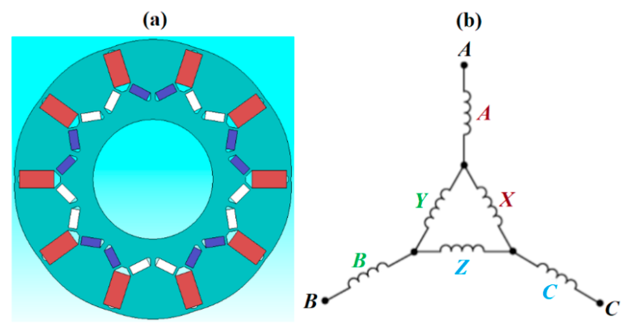
2.1. Design Considerations

Electromagnetic analysis of the proposed electric motor was carried out using the JMAG finite element-based commercial code. The proposed design concept of the electric motor considered the recent development trend that directed toward the high torque density, high efficiency and high fault-tolerant capability. The multiphase fault tolerant permanent-magnet (PM) motor has received wide applications for electric vehicles (EVs) and aircraft [41,42]. Among the various types of PM, the fractional-slot concentrated windings (FSCWs) motors were employed due to the comparative advantages over the motors with conventional overlapped wingdings, such as short end windings, high slot-filling factor, high winding factor, low cogging torque, and good flux-weakening capability [43]. Particularly, a FSCW motor possesses relatively high inductance which can effectively restrain terminal short-circuit current and enhance the flux-weakening ability. However, a FSCW motor is generally limited by the excessive space harmonics in stator magnetomotive force (MMF). The large content of stator MMF harmonics produced high eddy loss in the PMs, which in turn reduced the efficiency, increased the rotor temperature, and raised the risk of irreversible demagnetization [44]. Thus, one of the electromagnetic design incentives for the present study was directed toward the reduction of the harmonic MMFs in FSCW machines. The most direct method was to segment the PMs [45]. However, the manufacturing cost and the maintenance difficulty were increased. Some other techniques with different winding arrangements are also proposed. Alternatively, the choose of an appropriate pole and slot combination [46,47,48] was commonly adopted, but with only marginal effectiveness for improvements. Thus, some complicated winding topologies were attempted for reducing the harmonics in the MMF. In this regard, the multilayer winding [49] which owned more than two-layer windings in one slot and the windings with different numbers of turns per coil side was proposed [50]. However, such winding topologies not only complicated the manufacturing process but also introduced an adverse impact to the machine. In [51], an 18-slot/8-pole six-phase PM machine, which was obtained by doubling the slot number of a conventional 9-slot/8-pole three-phase machine and adding another three-phase winding, was studied. The results showed that the flux distribution produced by the stator currents was improved with the six-phase winding designed as two sets of independent three-phase windings. However, the most harmful harmonics were not eliminated completely. For the present work, the electric motor of 12-slot/10-pole triple layer winding delta-star connection with segmented magnets was designed with the attempt to reduce the rotor eddy current losses of the FSCW motor. The winding layout presented exhibited the best MMF harmonic cancellation effects by eliminating the sub-harmonics and some of higher order harmonics. With regard to the segmented magnets, the arrangement and the segmentation reduced the eddy currents, consequently, reducing the thermal power generation in the rotor. While many types of winding connections could be used, such as the typical Y connection, it was noticed that the FSCW motor configuration could incur high rotor iron loss due to its rich spatial magneto-motive force (MMF) harmonics. In [52], it was reported that the Y + Delta connection was effective to reduce the harmonics and rotor loss. Thus, the present electromagnetic study examined the various power losses in association with the two types of winding connections, namely 2Y and Y + Delta connections. The electromagnetic design specifications for the proposed FSCW motor are itemized in Table 1.

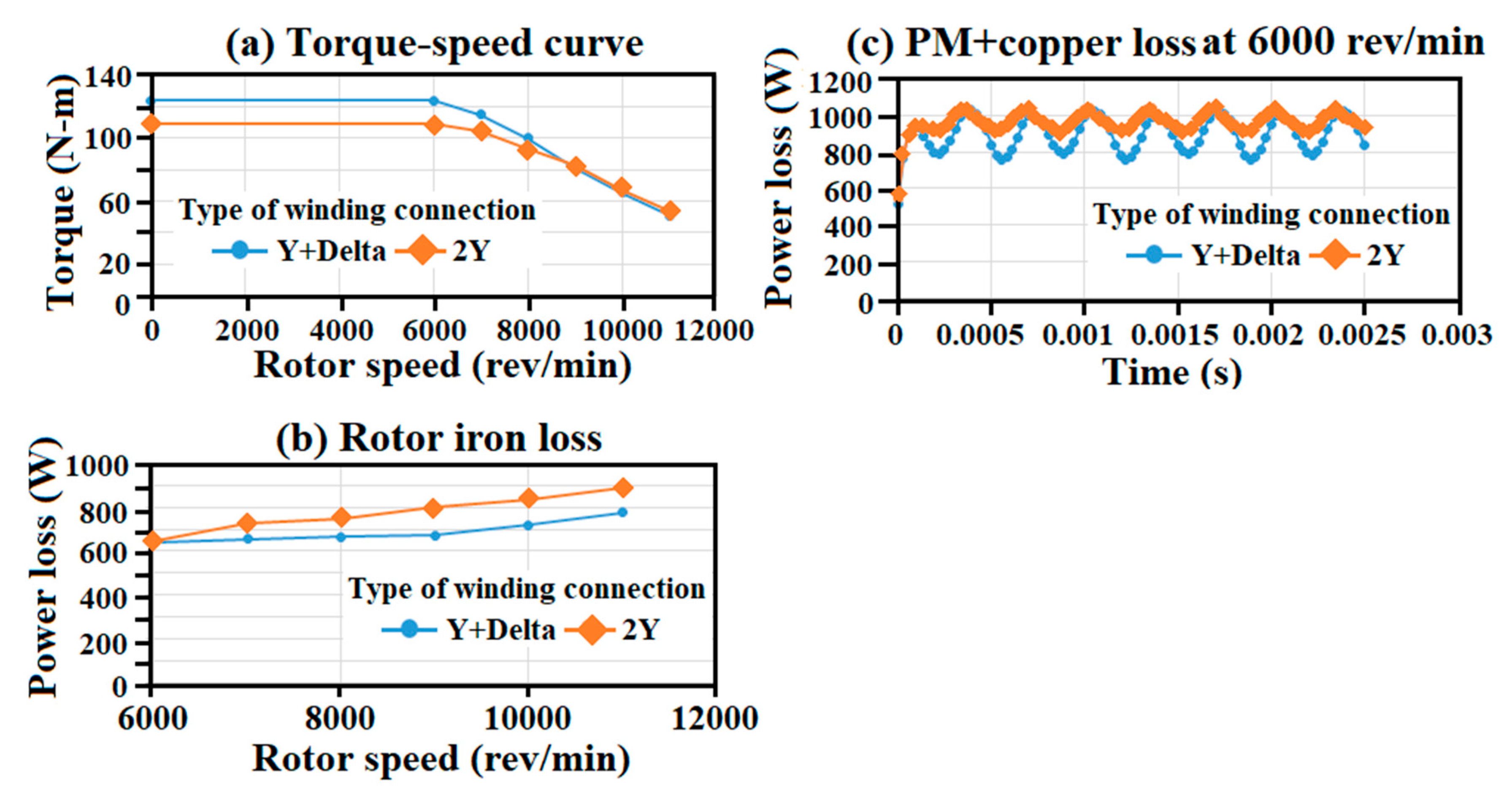
2.2. Results of Electromagnetic Analysis with the Thermal Powers Generated

The rotor and winding connection of the present FSCW motor were designed in order to minimize the rotor iron loss, increase the efficiency during high-speed operation, and achieve high constant power speed ratio (CPSR). The detailed geometric configurations for the motor are provided in the later section illustrating the thermal analysis. Figure 1a presents the proposed rotor topology, which the permanent magnets are arranged to achieve high air-gap flux density, high-speed, and high-demagnetization capability. The spoke magnet arrangement and the V type arrangement were respectively designed to improve the air-gap flux density and reduce the flux leakage produced in the shaft with the improvement of structural integrity for high-speed operation.
The winding connection shown in Figure 1b was designed to eliminate sub-harmonics and higher order harmonics that produced extra losses on the rotor and permanent magnets. In order to minimize the eddy current losses in the permanent magnets, the permanent magnets were divided into 9 pieces as shown in Figure 2. As compared by Figure 2 for the magnet loss density of (a) non-segmented magnet (b) segmented magnet with the harmonics at 1000 Hz, the power loss density is reduced significantly after dividing the magnet. The maximum local loss density was reduced from 2.3 × 10⁶ to 1.47 × 10⁶ Wm−3. Acting by the loss reduction in the rotor, the thermal power generated in the rotor was decreased accordingly.
In view of the electromagnetic impacts caused by the present spoke-V type magnet arrangement, the comparative differences in the distribution of the magnetic flux and the various performance factors against those generated by the conventional flat-type arrangement are, respectively, compared in Figure 3 and Table 2. With such comparative study, the stator, winding configuration, material and magnet volume are identical for the present spoke + V and the conventional flat-type rotor topologies. Table 2 summarizes the simulation conditions and results for the electric motors with the spoke + V and the flat-type magnet arrangements.
As compared by Figure 3 for the magnetic flux distributions of the electric motors with (a) flat (b) spoke + V magnet arrangements, the conditions of magnetic flux saturation are similarly kept for the fair iron loss, power and torque comparisons. The more detailed comparisons of the flat and spoke + V designs shown in Table 2 indicate that the present spoke + V design can achieve higher torque than the flat-type topology with the same amount of magnet. In addition, due to the present spoke + V magnet arrangement, the rotor loss was considerably reduced from that with the conventional flat-type design, leading to the consequent reduction in the thermal power generation within the motor.
Another factor worth noting that affected the electromagnetic performances was the type of winding connection. Figure 4 compares (a) torque-speed curve (b) rotor iron loss (c) PM + copper loss for the spoke + V design with the Y + Delta and 2Y winding connection. As compared by Figure 4a, the higher torque outputs at the rated speeds less than 9000 rev/min are found for the Y + Delta winding connection. With the higher power output at the same electrical power supply, the motor efficiency is higher for the Y + Delta winding connection. Consequently, as compared by Figure 4b,c, the rotor iron loss and the PM + copper loss for the spoke + V design with the Y + Delta winding connection are consistently less than the 2Y counterparts.
Justified by the results of the present electromagnetic analysis, the segmented magnets arranged as spoke + V pattern with the Y-delta winding connection were adopted for the following thermal analysis. The various losses required for the thermal analysis at the rated and maximum loading conditions predicted by the electromagnetic analysis are summarized in Table 3.

3. Thermal Analysis Methods

3.1. Heat Convection of Spiral Coolant Channels with and without Sectional Twist

The turbulent flow and heat transfer of the spiral channels with and without the sectional twist were simulated using the ANSYS-Fluent code to acquire the channel-averaged convective heat-transfer coefficients as the thermal boundary conditions for the present water jacket around the motor stator. In the water jacket of the electric motor shown by Figure 5a, the two types of spiral channel were both square sectioned with the channel hydraulic diameter, d, of 20 mm, which was selected as the characteristic length for evaluating Reynolds, Re, and Nusselt, Nu, numbers. For both the spiral coolant channels without and with the sectional twist, the axial pitch and mean radius of each spiral channel were 26 mm and 128 mm, respectively. For the spiral channel with the sectional twist, the twist ratio was 3.9 d. The configurations of the spiral channels without and with the sectional twist are shown by Figure 5b. The zoom-in plots in Figure 5b depict the near-wall grid structures for the two spiral channels. With the present fine grids, the enhanced wall treatment (EWT) that combined two-layer enhanced wall functions was adopted for calculating the viscosity-affected fluid velocities and temperatures in the near wall region and resolving the turbulence behavior down to the viscous sublayer.
The flow continuity, momentum, energy and turbulence equations were solved iteratively using the Semi-Implicit Method for Pressure Linked Equations (SIMPLE) algorithm. The uniform fluid velocities at channel Reynolds numbers of 5000, 10,000, 15,000, 20,000 and 25,000 were specified at the flow entry plane with the fixed pressure outlet condition at the channel exit. Such pressure outlet condition provided the better convergence and accuracy than specifying the outflow boundary condition as the swirling flows with noticeable velocity gradients were expected for the spiral channel flows. The turbulent intensity level at flow entrance was set as 5%. The uniform heat fluxes were imposed on the four channel walls of the two spiral channels with turbulent water flows. Thus, the streamwise variations of fluid bulk temperature (Tb) were assumed to be linearly increased in the streamwise direction along each spiral channel. Local fluid bulk temperatures were calculated by the enthalpy balance method with the water flow rates determined from the predefined Reynolds numbers for calculating Nu using the Tw field generated by the ANSYS-Fluent code. Residuals of iterations were set to 1 × 10⁻6 for energy equation and 1 × 10⁻4 for all other flow equations as the convergence criteria.
The spiral channels with and without the sectional twist were meshed with the multi grid elements. The Green-Gauss node based spatial discretization scheme was used in the present numerical scheme. The body-size control parameter was adopted to control the element size. Ten prism layers with growth rate of 1.2 and transition ratio of 0.272 were generated normal to the heated wall to resolve the large near-wall fluid temperature and velocity gradients. The grid independency test using the Re-Normalization Group k-ε (RNG k-ε) turbulence model at Reynolds number of 10,000 was carried out by comparing the mean exit axial flow velocity calculated from the present numerical model with different grids as shown as compared by Figure 6a. For satisfying the grid independency requirement of each spiral channel with the discrepancies in the mean streamwise flow velocities less than 0.1% between two successive grid structures as shown by Figure 6a, the minimum numbers of element required were 1.21 and 4.06 million for the spiral channels without and with the sectional twist respectively. Thus, the grid structures with 1.21 and 4.06 million of elements were adopted for the present Computational Fluid Dynamics (CFD) simulations using the spiral channels without and with the sectional twist. With both the grid structures, the corresponding averaged y+ values over the channel walls were less than unity.
For disclosing the streamwise length required to reach the developed flow region, the streamwise variations of the sectional averaged fluid temperatures for the turbulent flows through the spiral channels without and with sectional twist are compared with the streamwise gradient of fluid bulk temperature evaluated from the enthalpy rise along the spiral channel. With the prescribed uniform heat flux over the inner walls of each spiral channel, the streamwise gradients of local or averaged fluid temperature are identical with the streamwise gradient of fluid bulk temperature at the developed flow region. Using the grid structures satisfied the grid independency criterion, the streamwise variations of the sectional averaged fluid temperatures along the spiral channels without and with the sectional twist were calculated by using the RNG k-ε turbulence model. As typified by Figure 6b at Re = 10,000, the disparities between the streamwise gradients of the sectional average fluid temperature and the fluid bulk temperature evaluated from the streamwise enthalpy rise became negligible after two spiral turns for both channels. Thus, the flow in each of the present spiral channel was treated as the developed flow after two spiral turns.
The selection of suitable turbulence model to unravel the thermal fluid phenomena in the two spiral channels was based on the comparative validation results. From the converged solutions of the various turbulence models, namely standard k-ε, RNG k-ε and k-Ω models, the calculated averaged Nusselt numbers at the developed flow region were compared with the empirical correlations generated from the experimental data detected from the smooth spiral channel [53]. For also depicting the effectiveness of heat-transfer enhancement generated by the smooth spiral channel, the numerical and experimental heat-transfer results were normalized with the Dittus-Boelter reference levels that correlated with the Nusselt number, Nu0, of turbulent developed flow through smooth straight pipe. As compared in Figure 7, the channel averaged Nusselt number ratios obtained from the RNG k-ε model exhibit the smallest discrepancies of 7% at Re = 5000 and 2.3% at Re = 20,000 from the experimental data among the results predicted by the various turbulence models; whilst the results evaluated from the k-Ω model showed the largest deviations. In general, the better validation results of RNG k-ε model over standard k-ε model for the present spiral channel were mainly associated with the improved ε equation in the RNG k-ε model that was suitable for rapidly strained flows and inclusion of swirling effect. As shown by Figure 7, the numerically predicted channel averaged Nusselt number ratios decrease with the increase of Dean or Reynolds number. But the predicted Nusselt numbers kept increasing with the increase of Dean or Reynolds number. Such Nu/Nu0 reductions driven by increasing Dean or Reynolds number reflected the lower power exponent of Re in the Nu equation of present smooth spiral channel less than that in the Dittus-Boelter correlation of 0.8. With 5000 ≤ Re < 20,000, the ratios of Nu/Nu0 for the present smooth spiral channel fall between 2.2–1.5.

3.2. Heat-Conduction Model

The motor configurations and the thermal powers converted from the electromagnetic losses were specified in Section 2. With the present numerical investigation, four cooling configurations, namely the two water jackets of smooth and twisted spiral coolant channels with and without cooling airflow through the shaft, were adopted for the motors with the identical electromagnetic designs.
Figure 8 depicts (a) grid structures of the simulation models with the four cooling scenarios (b) thermal network for evaluating the non-homogeneous effective thermal conductivities of stator winding. As shown by Figure 8a, the axial lengths for the motor components were 370 mm for the shaft, 153 mm for the rotor, 211 mm for the stator, and 330 mm for the water jacket. The annual air gap between the rotor with outer diameter of 128.68 mm and the stator with the inner diameter of 130 mm was 0.66 mm. With the outer diameter of the stator as 198 mm, the nominal thickness of the stator was 34 mm. The entire rotor assembly was driven by the shaft with the diameter of 44 mm. For the electric motor with shaft cooling using the forced convective air flow through the rotor, the diameter of inner bore in the shaft was 24 mm. The cylindrical water jacket fitted with the smooth or twisted spiral square channel encapsulated the outer surface of the stator. With the outer diameter of 270 mm, the radial span of the aluminum water jacket was 36 mm. The height and width of the spiral coolant channel in the cooling jacket was 20 mm. Similar to the aforementioned routine for the grid independency test using the temperature between the rotor and shaft at mid-location as the index, the mesh numbers required for satisfying the grid independency conditions for the cooling configurations of smooth and twisted spiral channels in the water jackets without and with shaft cooling were 5,043,524, 5,029,489, 4,921,293 and 4,904,494 respectively, resulting in the largest grid lengths in the range of 2.4–3.4 mm.
The thermal conductivities of the steel plates that constructed stator and rotor, the permeant magnetic steel plate in the rotor and the aluminum cooling jacket were 6.9, 20 and 237 Wm−1K−1 respectively. As listed in Table 3, the copper loss in the stator windings was 2200 W at the worst design scenarios. With the copper coils immersed in laminations at each winding slot of the stator at the volumetric filling ratio of 61%, the thermal conductivity of the laminated coils became non-homogeneous. Figure 8b illustrates the heat conduction network developed by present study for evaluating the non-homogeneous effective thermal conductivities in axial, radial and span-wise directions. As shown by Figure 8b, the lamination and copper wire were thermally connected in series for the span-wise and radial conductions; whereas the axial conduction was coupled in parallel. With the thermal conductivities of 400 and 2 Wm−1K−1 for the copper wire and the present lamination, the effective axial thermal conductivity of the winding coil was similar to the thermal conductivity of copper. But the low thermal conductivity of lamination significantly affected the effective span-wise and radial thermal conductivities of the laminated copper coils. Following the conceptual thermal conductive network shown by Figure 8b, the span-wise or radial effective thermal conductivity, keff, for the laminated copper coils in each stator winding slot was evaluated using Equation (1).
L k e f f = L C o p p e r k C o p p e r + L L a m i n a t i o n k L a m i n a t i o n
In Equation (1), L, LCopper and LLamination are the total radial or span-wise length of the coil; and the length scales for copper wires and lamination layers, respectively. The corresponding thermal conductivities for compound windings, copper and lamination were keff, kCopper and kLamination. With the identical axial length for the copper wire and the lamination, the length ratio between the copper wire and the lamination layer was reduced to the square root of the volumetric slot filling ratio. For the present slot filling ratio of 61% and the thermal conductivity of the lamination layer as 2 Wm−1K−1, the effective spanwise, radial and axial thermal conductivities of the stator winding were 36.53, 36.53 and 400 Wm−1K−1, respectively.
Instead of prescribing the heat flux over the contact boundaries of all the components that composed the electric motor, the thermal boundary conditions for the rotor and stator were emulated more realistically by treating the copper coils in the stator and the magnets in the rotor as heat-generation components. The rotor iron loss of 571 W, stator iron loss of 953 W, stator copper loss of 2200 W and rotor magnet loss of 934 W were converted into the volumetric thermal powers generated by these components in the present thermal model as 455,371, 345,220, 4,099,895, and 3,138,633 Wm−3, respectively. As shown by Figure 8a, a number of tiny axial air gaps were scattering within the rotor. The airflows in these axial gaps were assumed as stagnant with the heat transmissions to be dominated by the heat conduction. On the outer surface of the cylindrical casing in contact with the atmosphere, the free convective thermal boundary conditions were assumed with the electric motor orientated horizontally. With the environment temperature set at 40 °C, the fluid temperatures for the air gap between the rotor and stator and over the two axial flat endwalls of the electric motor were determined as averaged film temperatures. The film temperature of the Taylor vertical flow was set as the average of the rotor outer wall, stator inner wall and the environment temperatures.
For establishing the convective thermal boundary condition inside the spiral coolant channel of the water jacket around the stator, the turbulent flow and heat transfer were individually analyzed to acquire the channel averaged convective heat-transfer coefficient. The thermal boundary conditions over all the solid–fluid interfaces were defined by Equation (2):
k w T w n = h ( T w T f )
where kw and Tw stand for the thermal conductivity and temperature of the component; n, h and Tf are the coordinate normal to the solid–fluid interface, the convective heat-transfer coefficient over the solid–fluid interface and the referenced fluid temperature which is the local fluid bulk temperature along the spiral channel or the film temperatures of Taylor flow and rotating disc type airflow over two axial ends of the rotor. The environmental temperature and the water flow entry temperature were set as 40 °C.
Regarding the various h values for different flow regimes in Equation (2), the h values of the coolant flow through the spiral channels without and with the sectional twist in the water jacket were predefined by the aforementioned CFD simulation. The heat convection taking place between the cylindrical rotating rotor and the static stator was governed by the well-known Taylor vortical flow. Whereas the Couette-type airflow driven by the circular endwall of the rotating rotor governed the heat convection prevailing over the two axial ends of the rotor. The convective heat tarsier rate from the outer surface of the rotating cylinder to the surrounding fluid was prescribed for the thermal boundary condition over a portion of the shaft that extended outside of the rotor. For the design scenario with airflow cooling through the hollow shaft, the h value was affected by the through-flow rate and rotor speed. In order to acquire the convective heat-transfer coefficient of the Taylor flow in the rotor-to-stator annual air gap for defining the thermal boundary condition specified by Equation (2), the experimental heat-transfer data collected from the literature for Taylor flows [53] were displayed in Figure 9.
As shown by Figure 9, the Nusselt numbers of Taylor flows, NuTaylor, generated by the various research groups converge into a unique data trend that is well correlated by Taylor number, Ta, defined as:
Ta = [ω2R1(R2 − R1)3]/υ2
In Equation (3), R2 and R1 are the radii of inner stator and outer rotor; R2 − R1 is the rotor-to-stator radial clearance; ω stands for the angular speed of the inner rotating cylinder and the kinetic viscosity, υ, was evaluated at the reference fluid of the Taylor flow. It is noticed that the characteristic length for the NuTaylor data collected in Figure 9 was the hydraulic diameter of the annual flow, Dh, defined as (R2 − R1). With the knowledge of NuTaylor, the convective heat-transfer coefficient of the Taylor flow, hTaylor, in a motor was calculated by Equation (4).
hTaylor = NuTaylor × kf/(R2 − R1)
After removing the data set deviated from the converged overall data trend reviewed in [53], the NuTaylor correlation was devised as Equation (5).
NuTaylor = 0.1548 × Ta0.3039
With the present simulation conditions of R1 = 64.34 mm, R2 = 65 mm at the rotor speed of 6000 rpm, the Taylor number was determined as 4.64 × 10⁷. Using Equation (5), NuTaylor was found to be 33.09 to provide the hTaylor of 100.1 Wm−2K−1. With such low hTaylor, a convective thermal barrier was formulated between the rotor and stator to limit the heat flux transmission from the rotor to the stator. Thus, the present study also examined the rotor cooling effects on the thermal field of the electric motor by using the hollow shaft with the through airflow.
For the electric motor with the forced convective cooling airflow through the shaft, the heat-transfer correlation for an axially rotating hollow shaft was previously reported [54] as:
NuShaft = 0.019Re0.93 + 8.51 × 10⁻⁶Rer1.45 when 1.6 × 10³ < Rer < 2.77 × 10⁵;
or NuShaft = 2.85 × 10⁻⁴Rer1.19 when Rer > 2.77 × 10⁵
In Equation (6), the characteristic length selected to define the through flow Reynolds number, Re, and the rotational Reynolds number, Rer, were the inner diameter of the hollow shaft, d. At the shaft angular velocity of ω with the kinetic viscosity of the coolant, υ, evaluated at the entry airflow temperature, the rotating Reynolds number, Rer, was calculated by Equation (7).
Rer = ωd2/2υ
For the Couette-type airflow driven by the circular endwall of the rotating rotor, the heat convection prevailing over the two axial ends of the rotor was emulating as the flow between static and rotating circular disc with the Nusselt number, NuEndwall, evaluated from the empirical correlation [55] as Equation (8):
NuEndwall = hEndwallDd/kf = 0.36(ωDd2/υ)0.5 when Re = ωDd2/υ < 106
In Equation (8), hEndwall is the convective heat transfer rate of rotating endwall; Dd is the outer diameter of the rotating disc at angular velocity of ω. For defining the thermal convective boundary condition over the outer surface of the shaft that extended out of the rotor, the empirical correlation [56] that evaluated the Nusselt number over the outer surface of a heated rotating cylinder with the outer diameter Dc was adopted as Equation (9):
NuRotating cyl. = hRotating cyl.Dc/kf = 0.11(0.5Reω2 + GrDcPr)0.35
where hRotating cyl. was the convective heat transfer rate of rotating cylinder. The Grashof number, GrDc, and the other form of rotating Reynolds number, Reω, [56] were defined as Equations (10) and (11).
GrDc = ρ2βg(TwTf)Dc3/μ2
Reω =ρπωDc2/μ
Having determined the NuShaft of the internal coolant flow through the rotating hollow shaft and the Nuendwall for the Couette-type airflow driven by the circular endwall of the rotating rotor, the NuRotating cyl. of the rotating cylinder, and the heat-transfer coefficients around the inner surface of the hollow shaft, hShaft, on the two axial endwalls of the rotating rotor, hEndwall, and over the outer surface of the extended rotating shaft, hRotating cyl., were fed into Equation (2) as the prescribed thermal boundary conditions over the inner surface of the rotating hollow shaft, the two axial endwalls of the rotor and the outer surface of the extended rotating shaft.
For the conduction–convection model presented in the section of thermal analysis methods, the key factors that affected the numerical accuracies were the various convective thermal boundary conditions specified on the solid-fluid interfaces. Having assured that the present conduction model was satisfied with the grid independency criterion, the various convective boundary conditions deployed for the present conduction–convection model required the adequate verifications. As reported in this section, the convective boundary conditions on the inner surface of the rotating hollow shaft, over the rotating axial end of the rotor and on the outer surface of the shaft that extended out of the rotor were converted from the empirical correlations reported in [54,55,56] respectively. The Nusselt numbers of Taylor flows between the rotor and stator were based on the present correlation generated from the experimental data available in the literature. For the convective heat-transfer coefficients in the smooth spiral channel, the present predictions were satisfactorily validated by the experimental data [53]. Nevertheless, with the newly invented twisted spiral coolant channel proposed by the present study, there is no heat-transfer data available in the literature. Future validations for the turbulent heat transfer of twisted spiral channel are recommended once the relevant experimental results are available.

4. Results and Discussion

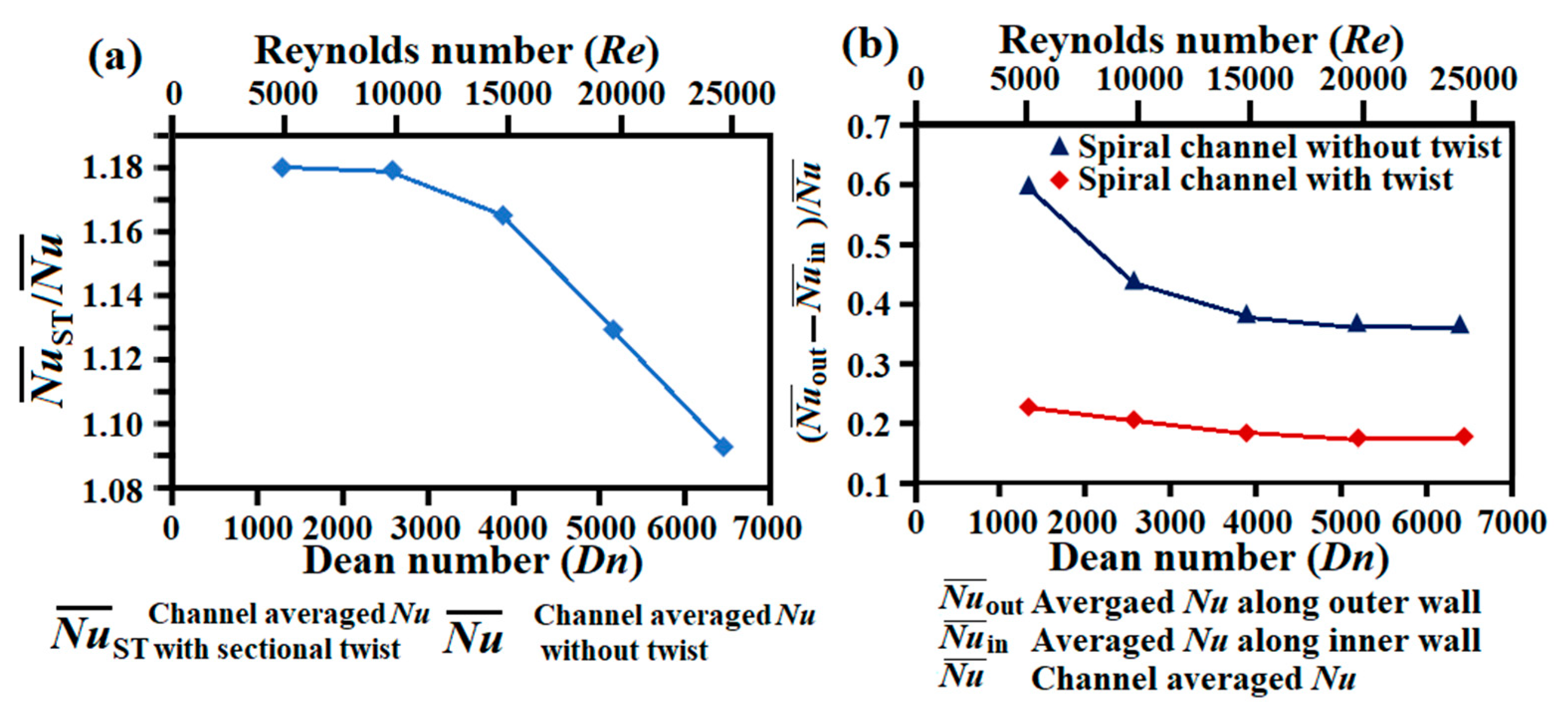
4.1. Convective Flow and Heat Transfer in Spiral Channels with and without Sectional Twist

In view of the forced convective heat-transfer performance for the present spiral water channel without or with the sectional twist, the flows reached the developed flow region after two turns as demonstrated in previous section. The following flow and heat-transfer results are focused on the developed flow region. Figure 10 compares the distributions of (a) streamwise velocity (b) circumferential velocity (c) turbulent kinetic energy, and (d) vorticity over the sectional plane at the third turn of the two spiral channels. For clear depictions of the distribution patterns of the streamwise and circumferential velocities, turbulent kinetic energy and vorticity, the scales selected in each set of plots of Figure 10a–d for the spiral channels without and with the sectional twist are different. Acting by the centrifugal forces directing radially outward that was oriented toward the outer wall of each plot collected in Figure 10, the streamwise velocities were skewed toward the channel outer wall, leading to the high streamwise velocities on the outer wall region as shown by Figure 10a. However, with the sectional twists to induce the torsional forces along the spiral channel, the distribution of streamwise velocities for the spiral channel with sectional twist is distorted in a counterclockwise direction as shown by Figure 10a. Nevertheless, as indicated in Figure 10a, the order of magnitudes for the streamwise velocities in both the spiral channels without and with the sectional twist is similar. In view of the sectional distributions of the circumferential velocity for the spiral channels without and with the sectional twist as compared by Figure 10b, the negative velocity components at the corners adjacent to the inner wall reflect the development of counter-rotating vortices against the main vortical flows occupying the channel core. In particular, the ranges of circumferential velocities induced on the sectional plane of the spiral channels without and with the sectional twist are −0.015–0.05 ms−1 and −0.14–0.189 ms−1, respectively. The magnitudes of the circumferential velocity, or the strengths of the sectional vortical flow, developed in the spiral channel with the sectional twist were about 5–10 times of those induced in the smooth spiral channel. Owing to the stronger sectional vortical flows and the distorted streamwise velocity profiles, which combined synergistically to augment the turbulences induced by the shear layers, the range of turbulent kinetic energy of 0–0.0072 m2s−2 for the spiral channel with the sectional twist was noticeably boosted from the range of 0–0.0036 m2s−2 in the smooth spiral channel as compared by Figure 10c. The turbulence augmentation caused by twisting the spiral coolant channel was about two times of that generated in the smooth spiral channel. Moreover, while the narrow bands of the high turbulent kinetic energy only developed along the outer and the two sidewalls along the smooth spiral channel, the flow structure developed in the twisted spiral channel considerably augmented the turbulent kinetic energy along the inner wall from the smooth-channel counterpart as compared by Figure 10c. Conjunction with the comparative results shown by Figure 10a, the moderated streamwise velocity gradients normal to the channel inner wall along with the suppressed turbulent kinetic energy seen in Figure 10c for the smooth spiral channel attributed to the lower regional drags on the inner wall with the accompanying lower regional heat-transfer rates. In comparison with the flow scenarios depicted in Figure 10a,c for the spiral channels with and without the sectional twist, sectional twist considerably augmented the momentum and heat-transport properties on the channel inner wall. The heat-transfer differences between the outer and inner walls of the spiral channel with the sectional twist were, accordingly, reduced from those with the smooth spiral channel, which will be illustrated later.
Another flow mechanism with great relevance to the heat-transfer performances of the present two spiral coolant channels is the magnitude and distribution of vorticity. As shown by Figure 10d, the high vorticity regions generally develop along the four channel walls for both the spiral channels without and with the sectional twist. The vorticity distribution for the smooth spiral channel is basically symmetrical about the x/d = 0.5 axis as shown by Figure 10d. With the sectional twist, the vorticity contours are distorted in clockwise direction in respect to the x-wise centerline as indicated in Figure 10d. Similar to the comparative results depicted by Figure 10a with the moderate fluid velocity gradients on the inner wall of the smooth spiral channel, the sectional twist considerably elevates the vorticity levels along the channel inner wall as compared by Figure 10d. Thus, the heat-transfer elevations from the smooth channel references caused by twisting the cross section of the present square spiral channel are most evident for the inner wall.
Based on the aforementioned comparative flow differences between the spiral channels without and with the section twist as typified by Figure 10, the corresponding heat-transfer variations caused by twisting the square sectioned spiral channel are indexed as N u S T ¯ / N u ¯ in which N u S T ¯ and N u ¯ stand for the channel averaged Nusselt numbers of the developed flows in the spiral channels with and without the sectional twist. As shown by Figure 11a where the variations of N u S T ¯ / N u ¯ ratios are plotted against Dean (Dn) or Reynolds (Re) number, the levels of N u S T ¯ are consistently higher than the N u ¯ counterparts over the range of 1290 ≤ Dn ≤ 6455 or 5000 ≤ Re ≤ 5000 for the present spiral channels. Within the present parametric conditions simulated, the ratios of N u S T ¯ / N u ¯ in the range of 1.18–1.09 decreased with the increase of Dn or Re. The other salient flow disparities between the spiral channels without and with the sectional twist emerged along the channel inner wall. As demonstrated by the flow results collected in Figure 10, the streamwise flow structure, the circumferential velocities, the turbulence intensity and the vorticity adjacent to the channel inner wall are prone to augmenting the inner-wall heat-transfer properties from those without the sectional twist. Thus, the outer-to-inner heat-transfer differences were accordingly reduced to offer the more uniform heat-transfer distributions along the periphery of the twisted spiral channel. As the non-uniformity of the peripheral heat-transfer variation for a spiral channel is mainly attributed to the outer-to-inner heat-transfer difference, the index to quantify the degree of heat-transfer uniformity is defined as ( N u o u t ¯ / N u i n ¯ ) / N u ¯ in which N u o u t ¯ , N u i n ¯ and N u ¯ represent the averaged Nusselt numbers along outer wall, inner wall and the four channel walls over the developed flow region.
Figure 11b compares the variations of normalized ( N u o u t ¯ / N u i n ¯ ) / N u ¯ values against Dean (Dn) or Reynolds (Re) number for the present spiral channels without and with the sectional twist. Bearing in mind that all the channel averaged N u S T ¯ / N u ¯ ratios are above than unity when the results compared in Figure 11b are examined. The ( N u o u t ¯ / N u i n ¯ ) / N u ¯ values of 0.6–0.38 for the smooth spiral channel are reduced to 0.22–0.18 as Dn increases from 1290–6455 or Re increases from 5000–25,000. As demonstrated by Figure 11, not only are the channel averaged Nusselt numbers elevated from the smooth spiral channel levels, the sectional twist can also significantly reduce the outer-to-inner Nusselt number differences to considerably improve the heat-transfer uniformity along the periphery of the square spiral channel in the water jacket of the electric motor.

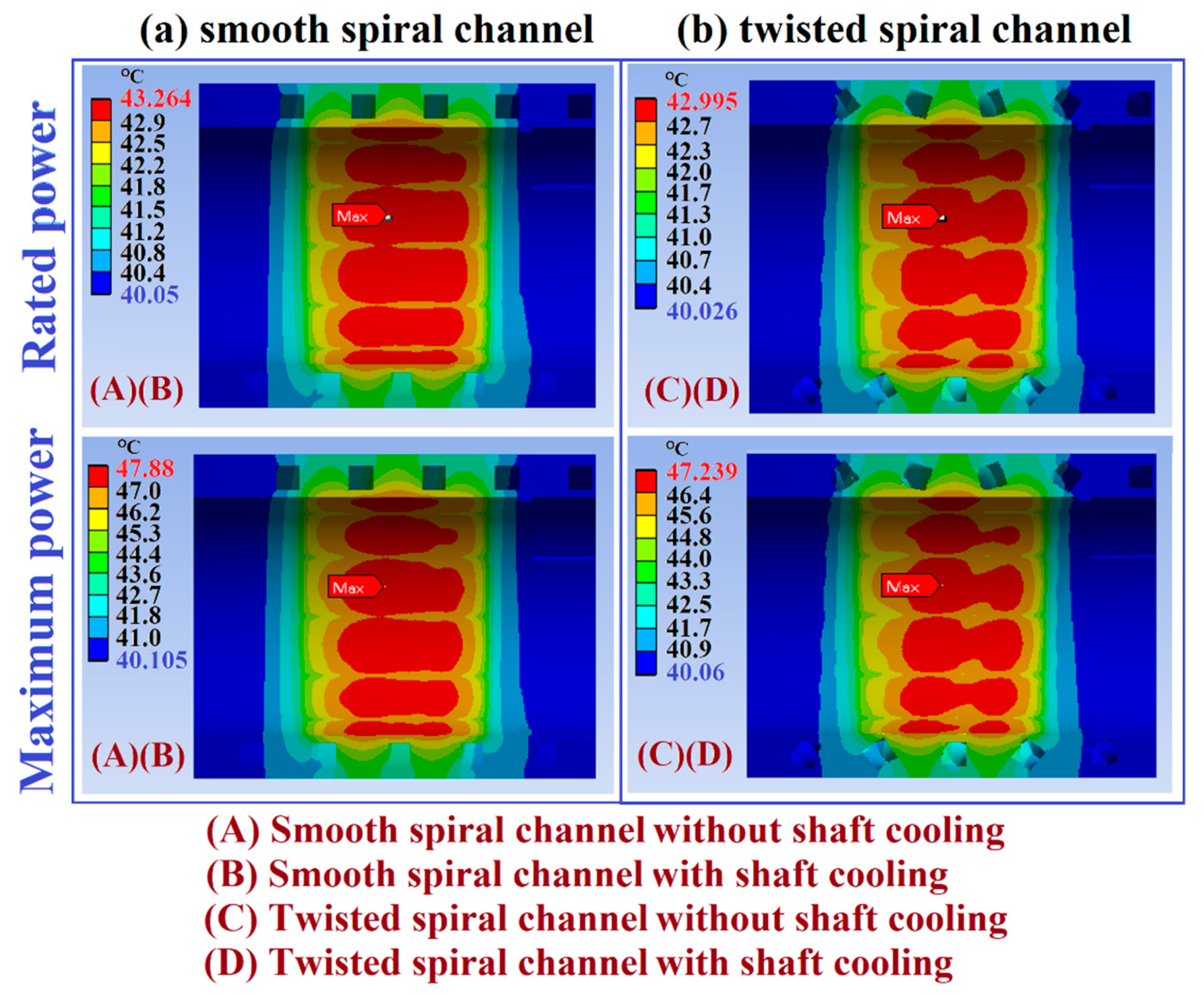
4.2. Temperature Fields of Electric Motors with and without Rotor Cooling

Having disclosed the heat-transfer characteristics of the present spiral channels without and with the sectional twist, the detailed material temperature fields of each component in the electric motor equipped with the four types of cooling configurations were examined. The overall temperature fields of the electric motor at the rated and the maximum power outputs with the accompanying power losses listed in Table 3 for the smooth spiral channel in the water jacket (A) without (B) with shaft cooling and for the twisted spiral channel in the water jacket (C) without (D) with shaft cooling are collected in Figure 12a,b respectively. In order to highlight the different temperature levels between the water jacket, stator, rotor and shaft, the range of color scales for the three-dimensional temperature plots compared by Figure 12 at the rated or maximum power conditions is identical for the cooling schemes of (A)(C) or (B)(D).
As seen in Figure 12, the characteristic patterns of the temperature distribution in the motors are almost identical disregarding the cooling scheme and the power rating. The Couette-type airflows developed at the rotating circular endwalls of the rotor and the rotation-driven heat convection over the outer surface of the extended rotating shaft have caused the evident temperature drops at the two ends of the rotor, disregarding the type of cooling scheme. The hottest temperature zone emerges along each axial magnet on the outer ring of the rotor even if the power losses of the stator were about 2.18 and 2.09 times of the rotor power losses at the rated and maximum loading conditions. While the temperatures on the sectional planes of the steel plates between the axial magnets in the rotor are noticeably less than the magnet counterparts, the rotor temperatures along the axial magnets and the steel plates are both considerably higher than the temperatures of the coil windings installed in the stator. Clearly, the Taylor vortices generated between the rotor and stator have formed a thermal barrier to prohibit the heat flux transmission from the rotor to the water jacket around the outer surface of the stator. Thus, with the smooth and twisted spiral channels in the water jackets, the maximum motor temperatures at the rated power were both 108.2 °C in the rotor for the cooling schemes (A) and (C) without airflow through the shaft. For the cooling schemes (B) and (D) equipped with the shaft cooling at Reynolds number of 10,000, the maximum temperature in the rotor at the rated power was reduced to 102.15 °C, irrespective to the different heat-transfer rates between the smooth and twisted spiral channels in the water jacket surrounding the motor casing. At the maximum loading conditions, the hottest spots in the motor reached 191.13 °C and 179.02 °C for the (A)(C) conditions without shaft cooling and (B)(D) conditions with airflow through the hollow shaft respectively. The shaft cooling was effective for reducing the rotor temperatures. But the thermal impact of the stator water jacket cooling on the temperatures of the rotor was diminished due to the thermal insulation layer formulated by the Taylor vortices in the rotor-to-stator annual air gap.
In order to discern the thermal impacts caused by the different cooling schemes, the temperature distributions are subsequently compared at the component level using the different temperature scales for presenting the thermal fields in the various motor components. The sectioned 3-D thermal fields and the corresponding temperature profiles with the (A)(B)(C)(D) cooling schemes for shaft, rotor, stator and water jacket at the maximum load are depicted in Figure 13, Figure 14, Figure 15 and Figure 16 respectively. Following the results demonstrated by Figure 12, the patterns of temperature distributions in all the motor components were similar at the rated and the maximum loads. With the thermal barrier of Taylor vortical flows in the rotor-to-stator air gap, the different spiral channels in the water jacket of the stator exhibited diminished influence on the thermal fields in the shaft and rotor as compared by Figure 13 and Figure 14. Figure 13 compared the surface and sectioned temperature distributions for the solid and hollow shafts at rated power (a) without (b) with shaft cooling and at maximum power (c) without (d) with shaft cooling for water jackets with smooth or twisted spiral channel.
As shown by Figure 13, the thermal fields of the solid shaft were governed by the conductive heat transfer. The maximum temperature developed at the inner core of the solid shaft. For the hollow shaft cooled by the forced convective airflow, the hot spots emerged along the outer surface of the shaft. In addition to the different hot spot locations, the maximum shaft temperature of 80.1 and 131.57 °C in the solid shaft at the rated and maximum loads were respectively reduced to 70.535 and 109.72 °C on the outer surface of the hollow shaft. Nevertheless, as the temperature imprints of the shaft mainly reflected the regional heat fluxes conducted from the iron and the segmental magnets in the rotor, the patterns of the surface temperature distribution for the solid and hollow shafts were similar. With the conduction dominant scenarios for the solid and hollow shafts shown by Figure 13, the sectional temperature plots exhibited the typical linear axial decays from the hot cores toward both axial ends. As disclosed by the surface temperature distributions for the solid and hollow shafts shown by Figure 13, the presence of the slot for inserting the square-sectioned pin that connected shaft and rotor incurred the three-dimensional conduction effect to distort the regional temperature field and increase the local temperature gradients and hence the thermal stresses along the pin slot.
As mentioned, the presence of Taylor vortices in the stator-to-rotor air gap annihilated the stator cooling impact on the thermal fields of the rotor and stator. This is reconfirmed by the almost identical rotor temperature distribution with the water jacket of smooth or twisted spiral channel. Thus, the characteristic thermal fields for the cooling conditions (A)(C) without shaft cooling and for the conditions (B)(D) with shaft cooling are typified in Figure 14 at the rated load (a) without (b) with shaft cooling and at the maximum load (c) without (d) with shaft cooling. As compared by Figure 14a,b or Figure 14c,d, the shaft cooling remained effective to reduce the maximum rotor temperature from 107.52 to 102.2 °C at the rated power and from 190.46 to 177.32 °C at the maximum power. Cross-examining the surface temperature contours between Figure 14a,b, and between Figure 14c,d, the presence of shaft cooling extended the axial span of the high temperature band on the outer surface of the rotor from the scenarios without shaft cooling. By way of motor load increase from the rated to the maximum loads, the hot spot on the rotor seen in Figure 14a,b became localized as shown by Figure 14c,d. Due to the forced convective airflows developed at the two axial ends of the rotating rotor and over the outer surface of the extended rotating shaft, the temperature contours decayed axially toward the two axial ends of the rotor. After reviewing all the temperature contours sectioned through the rotor, the hottest spot in the rotor consistently emerged at the axial mid-span central in each magnet irrespective to the cooling and loading conditions.
While the thermal barrier formulated by the Taylor vertical flows has blocked the shaft-cooling effect on the thermal field of the stator, the high thermal conductivity of the aluminum cooling jacket has smoothed out the temperature distributions around the smooth or twisted spiral coolant channel, leading to the negligible thermal impact in association with the different cooling conditions (A)(B)(C)(D); even if the differential convective heat-transfer rates and near-channel geometries have caused different temperature fields in the present two types of water jackets as demonstrated later. Thus, the typified surface temperatures and the temperature distributions on the mid-plane section of the stator with the cooling conditions (A)(B)(C)(D) at (a) rated (b) maximum loads are collected in Figure 15. Referring to the general arrangement of each cooling configuration shown by Figure 8a, the interconnected coil bends at the two axial ends of the stator are not permissible to be in direct contact with the inner annual surface of the cooling water jacket. As shown by Figure 15, two hot annual rings corresponding to the interconnected coil bends at the two axial ends are generated. The axial conduction of the cooling jacket and the airflow surrounding the two axial ends of the stator played dominant roles for cooling of the interconnected coil bends at the two axial ends of the stator. At the rated load, the hottest spot of the stator emerged in the hot rings at the two axial ends of the stator. However, as indicated in the sectional temperature plots shown by Figure 15a,b, the maximum temperature spots in these two annual rings at the rated load shifted axially inward at the maximum lead due to the elevated concentrate heat flux emitted from the coil windings in the stator. By increasing the rated load to the maximum load, the maximum temperature in the stator was raised from 79.27 °C to 122.69 °C for all the cooling configurations.
The differential heat-transfer impacts on the thermal field of the water jacket owing to the various convective performances in the smooth and twisted spiral channels are illustrated by comparing the sectional temperature distributions through the central axial plane at the rated and maximum loads for (a) smooth (b) twisted spiral channel without and with shaft cooling in Figure 16. Once again, the shaft cooling exhibited a diminished thermal impact on the temperature field in each water jacket due to the thermal barrier formulated by the Taylor vertical flows.
The characteristic temperature distributions with and without shaft cooling, namely the cooling schemes (A)(B) and (C)(D), were almost identical, which is typified by the plot collected in Figure 16. A common feature shown by the temperature distributions seen in Figure 16 for both water jackets is the zebrine pattern with higher temperature bands at the locations corresponding to the coil windings. The temperatures at the two axial ends of each water jacket were considerably less than those in the middle core as the axial extensions of the water jacket were not in contact with the heat source of the stator. The maximum temperatures in the water jackets fitted with the smooth and twisted spiral channels were 43.264 and 42.995 °C at the rated power; which were raised to 47.88 and 47.239 °C at the maximum loading condition, respectively. The high thermal conductivity of the aluminum cooling jacket was beneficial to moderate the temperature peaks. While the maximum temperatures in the water jacket, which were less significant for motor applications, remained similar for both smooth and twisted spiral channels, the low temperature zones in the water jacket with the twisted spiral channel were considerably extended from those found in the water jacket with the smooth spiral channel as compared by Figure 16. Such extension of the low temperature regions caused by the twisted spiral channel has led to reductions of the average temperature by about 10% from those with the smooth spiral coolant channel. In view of the relevant engineering applications such as the cooling systems of the cylinder liner and cylinder head in a heavy duty reciprocating engine, the thermal performance improvements using the twisted spiral coolant channel is worthy of future study.

5. Conclusions

An electromagnetic-thermal coupled analysis using the convection–conduction thermal model that permitted the prediction of the detailed temperature distributions in each component of an electric motor was proposed as a design tool for the thermal management of an electric motor. The present thermal analysis method adopted the non-homogeneous effective thermal conductivity model for coil winding with the full definitions of the convective thermal boundary conditions for disclosing the detailed temperature distributions in all the motor components subjected to the various cooling configurations. Based on the results obtained from the 80 kW interior permanent magnet synchronous electric motor with power density of 3.6 kW/kg using four different cooling schemes, the following salient points for heat transfer and thermal management of the electric motor were concluded.
  • The present invention of the segmental spoke + V type magnet arrangement in the rotor along with the Y + Delta connection for the stator windings improved the electromagnetic efficiency and hence reduced the various power losses to moderate the thermal loads of the motor-cooling systems.
  • With the sectional twists to induce the torsional forces along the newly devised twisted spiral channel, the circumferential velocity, turbulence kinetic energy and vorticity were boosted to be in favor of heat-transfer augmentations from those developed along the smooth spiral channel. At the parametric conditions of 1290 ≤ Dn ≤ 6455 or 5000 ≤ Re ≤ 25,000, the N u S T ¯ / N u ¯ ratios were elevated to 1.18–1.09 but decreased with the increase of Dn or Re. As the flow mechanisms adjacent to the channel inner wall were modified by the sectional twist that improved the inner-wall heat-transfer properties from those in the smooth spiral channel, the outer-to-inner heat-transfer differences were considerably reduced to offer the more uniform heat-transfer distributions along the periphery of the twisted spiral channel.
  • Acting with the conduction effect of the aluminum water jacket, the increase of heat-convective coefficients from the smooth spiral channel levels using the present twisted spiral channel was effective for reducing the average temperatures about 10% but less effective to alter the characteristic thermal field in the water jacket of the motor.
  • With the airflow through the hollow shaft, the hot spots shifted from the inner core of the solid shaft to the outer surface of the hollow shaft with the considerable temperature reductions from those developed in the solid shafts at both rated and maximum loads.
  • While the Taylor vortical flows in the rotor-to-stator air gap are inevitable, the thermal barrier formulated by the Taylor flow prohibited effective heat transmission from the rotor to stator, leading to the diminished effect of the stator cooling condition on the thermal fields in rotor and shaft and the necessities for future developments of rotor cooling in order to increase the power density of an electric motor.

Author Contributions

Conceptualization, S.W.C., P.-S.W. and M.-F.H.; methodology, S.W.C. and P.-S.W.; software, W.L.C., J.-H.L., Y.-T.H., and J.F.C.; validation, W.L.C., and J.-H.L.; formal analysis, S.W.C., P.-S.W.; investigation, S.W.C., P.-S.W., M.-F.H. and J.F.C.; resources, S.W.C., P.-S.W. and M.-F.H.; Writing—Original draft preparation, S.W.C. and J.F.C.; Writing—Review and editing, S.W.C.; visualization, S.W.C., P.-S.W.; supervision, S.W.C., P.-S.W., M.-F.H.; project administration, S.W.C., P.-S.W., M.-F.H.; funding acquisition, S.W.C. and M.-F.H.

Funding

This research was funded by Ministry of Science and Technology, Taiwan, grant number MOST 108-2622-8-006-014.

Acknowledgments

The research work was supported by Ministry of Science and Technology, Taiwan, under MOST 108-2622-8-006-014 projects.

Conflicts of Interest

The authors declare no conflict of interest.

References

  1. Hita, Y.; Kesamaru, K.; Yoshida, K. Eddy-current loss analysis in PM of surface-mounted-PM SM for electric vehicles. IEEE Trans. Magn. 2000, 36, 1941–1944. [Google Scholar]
  2. Atallah, K.; Howe, D.; Mellor, P.H.; Stone, D.A. Rotor loss in permanent magnet brushless AC machines. IEEE Trans. Ind. Appl. 2000, 36, 1612–1618. [Google Scholar]
  3. Wrobel, R.; Mellor, P.; Popescu, M.; Staton, D. Power loss analysis in thermal design of permanent magnet machines: A review. IEEE Trans. Ind. Appl. 2016, 52, 1359–1368. [Google Scholar] [CrossRef]
  4. Yaohui, G.; Mohammad, K.; Yew, C.C.; James, D.W.; Xu, D.; Mircea, P.; James, G.; Dave, S.; Andrew, S. Cooling of automotive traction motors: Schemes, examples and computation methods—A review. IEEE Trans. Ind. Electron. 2019, 66, 1681–1692. [Google Scholar]
  5. Chang, S.W.; Chiou, S.F.; Su, L.M.; Yang, T.L. Free Convective Heat Transfer in Tilted Longitudinal Open Cavity. Heat Transf. Eng. 2005, 26, 46–64. [Google Scholar] [CrossRef]
  6. Farsane, K.; Desevaux, P.; Panday, P. Experimental study of the cooling of a closed type electric motor. Appl. Therm. Eng. 2000, 20, 1321–1334. [Google Scholar] [CrossRef]
  7. Trigeol, J.F.; Bertin, Y.; Lagonotte, P. Thermal Modeling of an Induction Machine Through the Association of Two Numerical Approaches. IEEE Trans. Energy Convers. 2006, 21, 314–323. [Google Scholar] [CrossRef]
  8. Nakahama, T.; Suzuki, K.; Hashidume, S.; Ishibashi, F.; Hirata, M. Cooling Airflow in Unidirectional Ventilated Open-Type Motor for Electric Vehicles. IEEE Trans. Energy Convers. 2006, 21, 645–651. [Google Scholar] [CrossRef]
  9. Kim, M.S.; Lee, K.S.; Um, S. Numerical investigation and optimization of the thermal performance of a brushless DC motor. Int. J. Heat Mass Transf. 2009, 52, 1589–1599. [Google Scholar] [CrossRef]
  10. Lim, C.; Airoldi, G.; Bumby, J.; Dominy, R.; Ingram, G.; Mahkamov, K.; Brown, N.; Mebarki, A.; Shanel, M. Experimental and CFD investigation of a lumped parameter thermal model of a single-sided, slotted axial flux generator. Int. J. Therm. Sci. 2010, 49, 1732–1741. [Google Scholar] [CrossRef]
  11. Li, H. Cooling of a permanent magnet electric motor with a centrifugal impeller. Int. J. Heat Mass Transf. 2010, 53, 797–810. [Google Scholar] [CrossRef]
  12. Lu, Y.; Liu, L.; Zhang, D. Simulation and Analysis of Thermal Fields of Rotor Multislots for Nonsalient-Pole Motor. IEEE Trans. Ind. Electron. 2015, 62, 7678–7686. [Google Scholar] [CrossRef]
  13. Chai, F.; Tang, Y.; Pei, Y.; Liang, P.; Gao, H. Temperature Field Accurate Modeling and Cooling Performance Evaluation of Direct-Drive Outer-Rotor Air-Cooling In-Wheel Motor. Energies 2016, 9, 818. [Google Scholar] [CrossRef]
  14. Chiu, H.C.; Jang, J.H.; Yan, W.M.; Shiao, R.B. Thermal performance analysis of a 30 kW switched reluctance motor. Int. J. Heat Mass Transf. 2017, 114, 145–154. [Google Scholar] [CrossRef]
  15. Arbab, N.; Wang, W.; Lin, C.; Hearron, J.; Fahimi, B. Thermal Modeling and Analysis of a Double-Stator Switched Reluctance Motor. IEEE Trans. Energy Convers. 2015, 30, 1209–1217. [Google Scholar] [CrossRef]
  16. Bianchi, N.; Bolognani, S.; Luise, F. Analysis and design of a brushless motor for high speed operation. In Proceedings of the IEEE International Electric Machines and Drives Conference IEMDC’03, Madison, WI, USA, 1–4 June 2003; Volume 1, pp. 44–51. [Google Scholar]
  17. Rehman, Z.; Seong, K. Three-D Numerical Thermal Analysis of Electric Motor with Cooling Jacket. Energies 2018, 11, 92. [Google Scholar] [CrossRef]
  18. Davin, T.; Pellé, J.; Harmand, S.; Yu, R. Experimental study of oil cooling systems for electric motors. Appl. Therm. Eng. 2015, 75, 1–13. [Google Scholar] [CrossRef]
  19. Nakahama, T.; Ishibashi, F.; Sato, K.; Kawano, K. Effects of Fan Blade Forward-Swept and Inclined Amounts in Electric Motors. IEEE Trans. Energy Convers. 2010, 25, 457–464. [Google Scholar] [CrossRef]
  20. Seshagiri-rao, G.V.R.; Subba-rao, V.V. Design of cooling fan for noise reduction using CFD. Int. J. Sci. Eng. Res. 2011, 2, 1–5. [Google Scholar]
  21. Krishna, S.R.; Krishna, A.R.; Ramji, K. An experimental study on the reduction of motor-fan noise by modification of the blade and shroud configuration. Mech. Eng. Sci. 2009, 224, 315–320. [Google Scholar] [CrossRef]
  22. Lu, Q.; Zhang, X.; Chen, Y.; Huang, X.; Ye, Y.; Zhu, Z.Q. Modeling and investigation of thermal characteristics of a water-cooled permanent-magnet linear motor. IEEE Trans. Ind. Appl. 2015, 51, 2086–2096. [Google Scholar] [CrossRef]
  23. Semidey, S.A.; Mayor, J.R. Experimentation of an Electric Machine Technology Demonstrator Incorporating Direct Winding Heat Exchangers. IEEE Trans. Ind. Electron. 2014, 61, 5771–5778. [Google Scholar] [CrossRef]
  24. Lindh, P.; Petrov, I.; Jaatinen-Varri, A.; Gronman, A.; Martinez-Iturralde, M.; Satrustegui, M.; Pyrhonen, J. Direct Liquid Cooling Method Verified with an Axial-Flux Permanent-Magnet Traction Machine Prototype. IEEE Trans. Ind. Electron. 2017, 64, 6086–6095. [Google Scholar] [CrossRef]
  25. Putra, N.; Ariantara, B. Electric motor thermal management system using L-shaped flat heat pipes. Appl. Therm. Eng. 2017, 126, 1156–1163. [Google Scholar] [CrossRef]
  26. Niti, K.L.; Kritsada, O.A.; Phrut, S.; Pradit, T. Thermal characteristics of a rotating closed-loop pulsating heat pipe affected by centrifugal accelerations and numbers of turns. J. Mech. Eng. 2017, 4, 35–50. [Google Scholar]
  27. Dehshali, M.E.; Nazari, M.; Shafii, M. Thermal performance of rotating closed-loop pulsating heat pipes: Experimental investigation and semi-empirical correlation. Int. J. Therm. Sci. 2018, 123, 14–26. [Google Scholar] [CrossRef]
  28. Chang, S.; Cai, W. Thermal performance of two-phase thermosyphon loop in rotating thin pad. Int. J. Therm. Sci. 2017, 112, 270–288. [Google Scholar] [CrossRef]
  29. Liou, T.M.; Chang, S.W.; Cai, W.L.; Lan, I.A. Thermal fluid characteristics of pulsating heat pipe in radially rotating thin pad. Int. J. Heat Mass Transf. 2019, 131, 273–290. [Google Scholar] [CrossRef]
  30. Zhenguo, L.; Lin, R. Optimization design of the spray evaporative-cooling large electrical machine. In Proceedings of the 19th International Conference on Electrical Machines and Systems (ICEMS), Chiba, Japan, 13–16 November 2016; pp. 1–4. [Google Scholar]
  31. Shedd, T.A. Next Generation Spray Cooling: High Heat Flux Management in Compact Spaces. Heat Transf. Eng. 2007, 28, 87–92. [Google Scholar] [CrossRef]
  32. Huang, Z. Thermal Design of Electrical Machines. Ph.D Thesis, Department of Measurement Technology and Industrial Electrical Engineering, Lund University, Lund, Sweden, 2013. [Google Scholar]
  33. Mellor, P.; Roberts, D.; Turner, D. Lumped parameter thermal model for electrical machines of TEFC design. IEE Proc. B Electr. Power Appl. 1991, 138, 205. [Google Scholar] [CrossRef]
  34. El-Refaie, A.; Harris, N.; Jahns, T.; Rahman, K. Thermal Analysis of Multibarrier Interior PM Synchronous Machine Using Lumped Parameter Model. IEEE Trans. Energy Convers. 2004, 19, 303–309. [Google Scholar] [CrossRef]
  35. Nategh, S.; Huang, Z.; Krings, A.; Wallmark, O.; Leksell, M. Thermal Modeling of Directly Cooled Electric Machines Using Lumped Parameter and Limited CFD Analysis. IEEE Trans. Energy Convers. 2013, 28, 979–990. [Google Scholar] [CrossRef]
  36. Zhang, P.; Du, Y.; Habetler, T.; Lu, B. A survey of condition monitoring and protection methods for medium-voltage induction motors. IEEE Trans. Ind. Appl. 2011, 47, 34–46. [Google Scholar] [CrossRef]
  37. Kolondzovski, Z.; Belahcen, A.; Arkkio, A. Comparative thermal analysis of different rotor types for a high-speed permanent-magnet electrical machine. IET Electr. Power Appl. 2009, 3, 279. [Google Scholar] [CrossRef]
  38. Ishak, D.; Zhu, Z.; Howe, D. Eddy-current loss in the rotor magnets of permanent-magnet brushless machines having a fractional number of slots per pole. IEEE Trans. Magn. 2005, 41, 2462–2469. [Google Scholar] [CrossRef]
  39. Nakano, M.; Kometani, H.; Kawamura, M. A study on eddy-current losses in rotors of surface permanent-magnet synchronous machines. IEEE Trans. Ind. Appl. 2006, 42, 429–435. [Google Scholar] [CrossRef]
  40. Ding, X.; Bhattacharya, M.; Mi, C. Simplified Thermal Model of PM Motors in Hybrid Vehicle Applications Taking into Account Eddy Current Loss in Magnets. J. Asian Electr. Veh. 2010, 8, 1337–1343. [Google Scholar] [CrossRef] [Green Version]
  41. Cao, W.; Mecrow, B.C.; Atkinson, G.J.; Bennett, J.W.; Atkinson, D.J. Overview of Electric Motor Technologies Used for More Electric Aircraft (MEA). IEEE Trans. Ind. Electron. 2011, 59, 3523–3531. [Google Scholar]
  42. Levi, E. Multiphase Electric Machines for Variable-Speed Applications. IEEE Trans. Ind. Electron. 2008, 55, 1893–1909. [Google Scholar] [CrossRef]
  43. Reddy, P.B.; El-Refaie, A.M.; Huh, K.K. Effect of Number of Layers on Performance of Fractional-Slot Concentrated-Windings Interior Permanent Magnet Machines. IEEE Trans. Power Electron. 2014, 30, 2205–2218. [Google Scholar] [CrossRef]
  44. Barrero, F.; Duran, M.J. Recent Advances in the Design, Modeling, and Control of Multiphase Machines—Part I. IEEE Trans. Ind. Electron. 2015, 63, 449–458. [Google Scholar] [CrossRef]
  45. Mirzaei, M.; Binder, A.; Funieru, B.; Susic, M. Analytical Calculations of Induced Eddy Currents Losses in the Magnets of Surface Mounted PM Machines with Consideration of Circumferential and Axial Segmentation Effects. IEEE Trans. Magn. 2012, 48, 4831–4841. [Google Scholar] [CrossRef]
  46. Parsa, L.; Toliyat, H.A.; Goodarzi, A. Five-Phase Interior Permanent-Magnet Motors with Low Torque Pulsation. IEEE Trans. Ind. Appl. 2007, 43, 40–46. [Google Scholar] [CrossRef]
  47. Fornasiero, E.; Bianchi, N.; Bolognani, S. Slot harmonic impact on rotor losses in fractional-slot permanent-magnet machines. IEEE Trans. Ind. Electron. 2012, 59, 2557–2564. [Google Scholar] [CrossRef]
  48. Aslan, B.; Semail, E.; Legranger, J. General analytical model of magnet average eddy-current volume losses for comparison of multiphase PM machines with concentrated winding. IEEE Trans. Energy Convers. 2014, 29, 72–83. [Google Scholar] [CrossRef] [Green Version]
  49. Alberti, L.; Bianchi, N. Theory and Design of Fractional-Slot Multilayer Windings. IEEE Trans. Ind. Appl. 2013, 49, 841–849. [Google Scholar] [CrossRef]
  50. Dajaku, G.; Gerling, D. Eddy current loss minimization in rotor magnets of PM machines using high-efficiency 12-teeth/10-slots winding topology. In Proceedings of the 2011 International Conference on Electrical Machines and Systems, Beijing, China, 20–23 August 2011; pp. 1–6. [Google Scholar]
  51. Patel, V.I.; Wang, J.; Wang, W.; Chen, X. Six-Phase Fractional-Slot-per-Pole-per-Phase Permanent-Magnet Machines with Low Space Harmonics for Electric Vehicle Application. IEEE Trans. Ind. Appl. 2014, 50, 2554–2563. [Google Scholar] [CrossRef] [Green Version]
  52. Vansompel, H.; Sergeant, P.; Dupre, L.; Bossche, A. A Combined Wye-Delta Connection to Increase the Performance of Axial-Flux PM Machines with Concentrated Windings. IEEE Trans. Energy Convers. 2012, 27, 403–410. [Google Scholar] [CrossRef]
  53. Guo, L.; Chen, X.; Feng, Z.; Bai, B. Transient convective heat transfer in a helical coiled tube with pulsatile fully developed turbulent flow. Int. J. Heat Mass Transf. 1998, 41, 2867–2875. [Google Scholar] [CrossRef]
  54. Fenot, M.; Bertin, Y.; Dorignac, E.; Lalizel, G. A review of heat transfer between concentric rotating cylinders with or without axial flow. Int. J. Therm. Sci. 2011, 50, 1138–1155. [Google Scholar] [CrossRef]
  55. Cobb, E.C.; Saunders, O.A. Heat transfer from a rotating disc. Proc. R. Soc. Lond. Ser. A 1956, 220, 343–351. [Google Scholar]
  56. Kays, W.M.; Bjorklund, I.S. Heat transfer from a rotating cylinder with and without cross flow. Trans. ASME Ser. C 1958, 80, 70–78. [Google Scholar]
Figure 1. (a) Rotor topology (b) Y + Delta winding connection.
Inventions 04 00069 g001
Figure 2. Magnet loss density of (a) non-segmented magnet (b) segmented magnet at harmonics of 1500 Hz.
Inventions 04 00069 g002
Figure 3. Magnetic flux distribution with (a) flat (b) spoke + V type magnet arrangement.
Inventions 04 00069 g003
Figure 4. Comparisons of (a) torque-speed curve (b) rotor iron loss (c) permanent-magnet (PM) + copper loss for spoke + V design with Y + Delta and 2Y winding connection.
Inventions 04 00069 g004
Figure 5. (a) water jacket with spiral coolant channel (b) grid structures of spiral channels without and with sectional twist.
Inventions 04 00069 g005
Figure 6. (a) grid independency test results (b) streamwise variations of sectional averaged fluid temperatures for turbulent flows through the spiral coolant channels without and with sectional twist at Re = 10,000.
Inventions 04 00069 g006
Figure 7. Comparisons of calculated channel averaged heat-transfer results over developed flow regime for smooth spiral channel using various turbulence models with experimental data [53] at 5000 ≤ Re ≤ 20,000.
Inventions 04 00069 g007
Figure 8. (a) grid structures grid structures of with four cooling scenarios (b) thermal network for evaluating non-homogeneous effective thermal conductivities of stator winding.
Inventions 04 00069 g008
Figure 9. Heat-transfer data of Taylor flows [53] and Nu correlation generated by the present study.
Inventions 04 00069 g009
Figure 10. Distributions of (a) streamwise velocity (b) circumferential velocity (c) turbulent kinetic energy (d) vorticity on sectional plane at 3.5 turns of spiral channels without and with sectional twist.
Inventions 04 00069 g010
Figure 11. Variations of (a) N u S T ¯ / N u ¯ against Dn or Re (b) ( N u o u t ¯ / N u i n ¯ ) / N u ¯ against Dn or Re for spiral channels without and with sectional twist.
Inventions 04 00069 g011
Figure 12. Three dimensional temperature distributions of electric motor at (a) rated (b) maximum power outputs with cooling schemes using smooth spiral channel in water jacket (A) without (B) with shaft cooling and twisted spiral channel in water jacket (C) without (D) with shaft cooling.
Inventions 04 00069 g012
Figure 13. Thermal fields of solid and hollow shafts at rated power (a) without (b) with shaft cooling and at maximum power (c) without (d) with shaft cooling for water jackets with smooth or twisted spiral channels.
Inventions 04 00069 g013
Figure 14. Characteristic thermal fields of rotor at rated load (a) without (b) with shaft cooling; at maximum load (c) without (d) with shaft cooling.
Inventions 04 00069 g014
Figure 15. Surface temperatures and temperature distributions on mid-plane section of stator at (a) rated (b) maximum loads.
Inventions 04 00069 g015
Figure 16. Sectional temperature plots through central axial plane of water jacket at rated and maximum loads with (a) smooth (b) twisted spiral channel.
Inventions 04 00069 g016
Table 1. Electromagnetic design specifications for the fractional-slot concentrated windings (FSCW) motor.
Electromagnetic Design Specifications for the FSCW Motor
Slot fill factor (%)61Max. Torque (Nm)240
Rated current density (A/mm2)12Max. Power (kW)120
Current at rated condition (A)212Rated. Power (kW)80
Current at max. condition (A)424Rated Speed (rpm)6000
Rated Toque (Nm)120Max. Speed (rpm)11,000
Power Density (kW/kg)3.6Operation at max. condition30
Table 2. Simulation conditions and results for spoke + V and flat-type magnet arrangements.
Simulation ConditionsSpoke + VFlatSimulation ResultsSpoke + VFlat
Base speed (rpm)60006240Rated Torque (Nm)124111
Voltage (V)400400Rated Power (kW)8078
Max. Current (A)600600Total Rotor Loss (W)10001500
Max. Torque (Nm)240216
Table 3. Motor losses with spoke + V segmented magnets and Y + delta winding connection at rated speed of 6000 rev/min.
Motor Losses at Rated Operation/6000 rpm/Unlimited Seconds
Rotor Iron loss (W)250Stator Iron loss (W)650
Magnet loss (W)300Copper loss (W)550
Motor Losses at Max. Operation at 6000 rpm
Rotor Iron loss (W)571Stator Iron loss (W)953
Magnet loss (W)934Copper loss (W)2200

