1. Introduction
One of the important topics in industry is the heat transfer in thermal systems and having knowledge about the thermal behavior of a system, which can help designers to design a system with high reliability and low energy consumption. Although many industrial cases have complicated geometry, we can find many simple geometries like a cavity in a variety of application like cooling of electronic devices, air conditioning, and solar systems [
1,
2,
3,
4,
5,
6,
7,
8,
9,
10]. Thus, the analysis of closed enclosures has attracted many researchers to study the flow and thermal behavior of a system for different fluids, geometries and boundary conditions such as partially heated, lid-driven, etc. The reason behind these simulations mostly was to understand the behavior of a thermal system in different conditions, deeply. For many of those applications, the flow nature is a mixture of forced convection and natural convection, which was solved by numerical methods since the numerical simulation is much cheaper compared to the experiments.
As discussed above, in many applications, the heat should be removed from devices and cool them down fast. The number of fluids that can be used for this purpose is limited by price, safety, and environmental restrictions. Due to this reason, water is a preferred coolant; it is cheap and accessible anywhere, however, the properties of water are not sufficient to remove heat from devices in specific applications. To overcome this problem, the thermal properties of water is needed to be enhanced using safe and cheap techniques. Adding another liquid to the water can improve some properties but most of the liquids have similar properties like high heat capacity and low conductivity coefficient. One of the common methods to enhance the thermal properties of fluids is to mix nano-particles with the particle size of less than 100 nm to fluids to reach the desired properties [
11]. Usually, nano-particles include particles of pure metals such as Cu, Au, Ag or metal oxides like Al
2O
3, SiO
2 or Fe
2O
3, which can enhance the thermal conductivity and heat capacity [
12,
13,
14,
15,
16,
17,
18,
19,
20,
21]. Choi et al. introduced nano-particle usage in utilizing heat transfer for the first time and showed that the usage of nanofluid could enhance thermal conductivity by 7 percent [
22].
Sherement and Pop conducted a research using Buongiorno’s mathematical model to find the most important parameter in mixed convection heat transfer in a lid-driven cavity filled with nanofluid [
23]. They studied the effect of Reynolds, Prandtl, Grashof and Lewis numbers and showed that the Richardson number, which is the driven factor, is the dominant function in flow and heat transfer characteristics. In addition, they found that the Lewis number has the least effect on the local and average Nusselt number. Das and Tiwar studied a differentially heated cavity filled with Cu water fluid to examine mixed convection and its effect on the Nusselt number [
17]. They found that the average Nusselt number was increased considerably by proliferating of the volume fraction of nanoparticles while the Richardson number is kept at unity. Mastiani et al. conducted a research on the mixed convection in a square cavity filled with water and copper nanofluid [
24]. The object of that research was to study the density maximum effect on the Nusselt number for different lid velocity. They found that at high Richardson numbers, the effect of density inversion is more important.
Alternatively, many researchers have studied the effect of different shapes of a cavity on the heat transfer parameters. Billah et al studied the unsteady mixed heat transfer in a triangle cavity for different inclinations [
25]. They used a mixture of water and copper-based nano-material with different volume fraction to study the effect of quartic temperature profile on the heat transfer coefficient of the vertical wall. They found that both temperature and flow field can be affected by the variation of solid volume fraction; the Grashof number still plays the most important role and the average heat transfer rate increases by 35% when the volume fraction increase from 0% to 25%. Nasrin and Parvin investigated the effect of water-Cu nanofluid on the buoyancy-driven flow in a trapezoidal cavity [
26]. Their research investigated the effect of different nano solid concentrations, Prandtl, Rayleigh numbers and aspect ratios of the geometry on the flow structure, isotherm lines, and Nu number. The results showed that the thermal and flow pattern are highly dependent on the Prandtl number and aspect ratio of geometry. In addition, they found that the highest heat transfer rate occurs for the case with the highest Pr and the smallest aspect ratio. Mixed convection of heat transfer in a lid-driven trapezoidal cavity was studied to find the influence of a combination of different nano-particles and water on the heat transfer rate by Kareem and Gao [
27]. Four types of nanofluid were studied for different rotational angle and Reynolds number. It was shown that the highest Nusselt number respectively occurs when we have SiO
2, Al
2O
3, TiO
2, and CuO water mixture. They also found that the Nusselt number increases as the volume fraction of nano-particles increases but it’s value decreases when the diameter of nano-particle increases.
Basak et al. analyzed the effect of uniform and non-uniform heating from the bottom of the cavity on the mixed convection in a square cavity [
28]. They used a finite element method to check the effect of Reynolds and Grashof number in laminar flow. They found that uniform heating is more effective than non-uniform heating. They also observed that uniform heating can increase the Nusselt number. Forced convection in a lid-driven three-dimensional cavity was studied by Sheikholeslami using Lattice Boltzman to find the effect of uniform Lorentz forces on the heat transfer rate and flow pattern [
29]. In addition, they considered the effect of Browninan motion on the nanofluid by Koo-Kleinstreuer-Li model, which affects the conduction coefficient and viscosity of the nanofluid. The cavity was filled with Al
2O
3 and the test case was examined for several Reynolds, Darcy, Hartman numbers and nano-particles concentrations. They found that the increase in Reynolds, Darcy number and the nanoparticle volume fraction could increase the heat transfer while the increase in the Hartman number can decrease it. Alrashed et. al studied the entropy generation and mixed convection in an open cavity that an isothermal block was placed at the center of the cavity to heat up the nanofluid [
30]. The flow could enter from the top of the cavity, pass through the domain, and leave the cavity from the bottom. They checked various Richardson numbers and block sizes and found that the nano-particles can be effective just for small block size. Their study also revealed that the entropy generation is highly dependent on the Ri number.
Recently, the flow in the 3D cavity has attracted more attention; researchers have studied the flow and heat transfer in a cubical cavity alone or with objects inside the cavity. The effect of mixed convection in a 3D double lid-driven cavity filled with water and Al
2O
3 was studied for different inclination by Hussain et al. [
31]. The most important objective of their research was to find the influence of nanoparticles volume fraction and Reynolds number on the patterns of temperature field. They realized that increasing of volume fraction to 8% could increase the local Nusselt number up to 50%. Khanafer and Aithal used a spectral element method to study the influence of a rotating cylinder on the mixed convection in a lid-driven cavity [
32]. They simulated both clockwise and counterclockwise rotation and they found that there is critical velocity at which the increase of Nusselt number stops; then the Nusselt number starts decreasing, thereafter. Mixed convection in a 3D cavity with two rotational adiabatic cylinders was analyzed to find the highest heat transfer rate for different nanoparticles [
11]. The cavity was filled with three different nanoparticles Cu, Al
2O
3 and TiO
2. It was shown that the Cu and water have the highest heat transfer rate and can enhance the heat transfer rate up to 38.1%. All these studies were conducted to analysis the heat transfer rate in different conditions that can help us find optimum design for industrial systems by optimization algorithm like genetic algorithm or artificial algorithm which is explained in detail in [
33]. Recently, researchers study the new type of nanofluid like carreau or Wilson and the application of nanofluids as phase change material [
34,
35,
36].
All these researches have studied the forced, natural or mixed convection characteristics either for 2D cavities or for a cubical cavity with different boundary conditions and nano-materials. No prior study, as much known to the author, is accessible for investigating laminar mixed convection in a 3D cylindrical cavity filled with nanofluid with isothermal boundary conditions. The cylindrical cavity can be found in many industries like turbomachinery and cold used for cooling of electronic devices. This gap that is recognized in literature has inspired authors to conduct the present work. This study will help designers to deeply understand the flow and thermal behavior of this system and it will help them to design systems that are more efficient. Hence, the present work is focused on the 3D analyses of mixed convection heat transfer in a cylindrical lid-driven cavity filled with Cu-Water nanofluid particularly the effect of Reynolds number (), Rayleigh number (), cavity aspect ratio () and for different nano-particles concentrations (). The problem definition, explanation of geometry, mathematical formulation and the numerical algorithm used in this work is presented in the following sections.
2. Problem Configuration
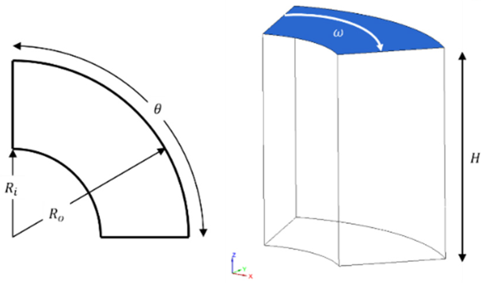
The geometry of this study includes a segment of a 3D hollow cylinder with a top moving wall which is found in many turbomachinery applications like thrust bearings. A schematic of the definition of physical domain of lid-driven cylindrical cavity is illustrated in
Figure 1 where
,
,
θ and
H, show the outer, inner radius, circumferential dimension, and height respectively.
The ratio of the inner radius to the difference of radiuses is kept fixed to unity and the ratio of height to the difference between radiuses, is studied for 3 ratios, 0.5, 1, 1.5. The circumferential dimension of the cylinder is 60 degrees for all cases. Except for the top wall of the cavity, which is a moving wall and rotates about the axis of the cylinder in the clockwise direction, all other walls are stationary and the no-slip condition is applied to all walls. In many industrial cases, the heat is entered to the domain from the top wall due to heat generation or friction and is removed from the bottom. Therefore, the top and bottom walls are assumed to be isothermal condition with temperature difference, ( and respectively, wherein ) and the vertical walls are assumed to be insulated and the adiabatic condition () is applied where is the normal to the surface of the walls. To simulate the effect of upthrust in fluid, the Boussinesq approximation is used to consider the influence of buoyancy on the heat transfer without consideration of density change in the domain. The fluid in the cavity is assumed to behave as a Newtonian fluid and all the thermos-physical properties of fluid are assumed to be independent of temperature field. The influence of radiative heat transfer from the walls and the dissipation effects are assumed to be negligible. In addition, the flow is assumed to be steady, incompressible, laminar and three-dimensional. With these assumptions, the governing PDEs (Partial Differential Equation) in the dimensional form are defined as
y-momentum with consideration buoyancy:
Energy equation:
where (
x,
y,
z), (
u,
v,
w),
p,
T, represent Cartesian coordinates, velocity in each direction, pressure, and temperature respectively. Moreover,
,
,
,
represent the thermal conductivity, viscosity, density and heat capacity of nanofluid which the calculation of these terms are presented in the next sections. To make the result more understandable, it is easier to present them with non-dimensional numbers, thus before solving the equations, they are mathematically rearranged and are presented as follows:
where
and the key parameters are defined as
,
,
. The corresponding boundary conditions for these equations in non-dimesnional form are
In convection problems, the most important parameter is heat transfer rate from the surfaces and it is determined by a non-dimensional parameter called Nusselt number. The Nusselt number is a function of Re, Pr and in nanofluid cases, the nanoparticle concentration [
37,
38]. The Nusselt number over a wall is defined as:
where
is defined as the convection coefficient over a wall. In non-dimensional form, the definition of Nusselt number is the gradient of non-dimensional temperature that for nanofluid problems is calculated as:
where
n shows the normal direction to the wall. To average the local Nusselt number, the following formula is used
where
is Nusslet number and
shows the area of each cell respectively.
3. Materials and Methods
The thermo-physical properties of materials used for this research are taken to be constant for both base fluid and nanoparticles. There are various models to calculate the effective viscosity, which can be used, but the Brinkman model (Equation (11)) is a simple model that can predict viscosity for the most combination of base fluid and nanoparticles [
39,
40]. In addition, the effective thermal conductivity of the nanofluid mixture is calculated with Wasp model (Equation (12)) [
41].
The density of the mixture is generally measured by experimental procedures but for the nanofluid, there is no experimental measurement and most researchers use the weighted averaging to calculate the effective density where the nanoparticle volume concentration is used as the weighted function. The other properties, which should be calculated to the lack of measurement, is the heat capacity and the same as density, a weighted averaging can be used to find the value of heat capacity of the mixture. However, the heat capacity can be calculated in two ways, one is that the averaging using just heat capacity,
, an the other one is averaging of
[
40]. In this work, the second method is used to find the heat capacity. Furthermore, to find the thermal expansion coefficient
, the same strategy is chosen. Equations (13)–(15) shows the equation used to calculate the nanofluid properties.
Table 1 depicts the properties of the water and copper which is used in this research.
4. The Numerical Approach
The steady-state Navier-Stokes and energy equation are discretized by Finite Volume method to yield a linear set of algebraic equations. The governing equations are solved by the in-house FORTRAN code that is built for structured orthogonal grids and it is used for simulation of laminar and turbulent regime flows [
42].
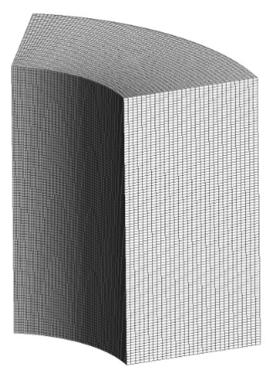
Figure 2 shows the structured grid generated for the cavity geometry with aspect ratio
. The QUICK (Quadratic Upstream Interpolation for Convective Kinematics) convection-diffusion scheme, that uses 3-point upstream weighted quadratic interpolation to calculate cell values on each cell, was used for the advective terms and for the diffusion terms, central second order term are used. The equation (16) shows QUICK interpolation for the uniform grid that is third order accurate method [
43].
where
shows all primitive variables like
and subscript shows the node index.
The rest of scheme used to solve this problem is central difference. The continuity equation is solved based on the famous Semi-Implicit Method for Pressure-Linked Equations (SIMPLE) algorithm and to increase the stability and to accelerate the convergence, the successive over-relaxation (SOR) method is utilized and the relaxation factors were set to 0.5 for momentum and energy equation and for pressure, it was set to 0.3 [
44,
45]. The linearized system for momentum and energy equations are solved using Gauss Seidel iterative methods [
46]. For more acceleration, the code is developed based on the OpenMP library to be able to run on the shared memory computer. This library allows us to divide computational tasks between threads of CPU (Central Processing Unit) without needing to divide the domain [
47]. Finally, the convergence of 3D momentum, energy and continuity are checked by the Equation (17) for all parameters to be sure that they all satisfied the convergence criteria, which is 10
−6. The
in the Equation (17) is the generic variable and it represents
in each equation. The
represents the coordinates of each node in the
xyz coordinate system (
x,
y and
z direction respectively) and the
shows the iteration numbers.
5. Verification and Validation
In every numerical study, choosing a proper size of grids is very important and it can affect the results. In addition, wise choosing of grid size can reduce the computational cost. To find the optimum case, by which the result is precise with the minimum possible grid, a grid independence study was done. Moreover, validation of numerical procedures used in the code was investigated. In the present work, the grid independence has been carried out for four different uniform grids (
). To find the most suitable number of grids, it was tried to run the case for the condition that needs the highest number of grids, thus the case for
and height ratio of 2 was selected. The geometry and grid made for this case is shown in
Figure 2.
Table 2 shows the details of grids, Nusselt number, percent of deviation relative to the G4 and computational time for each grid size. It was observed that the minimum and maximum deviation between the G1 and G5 is 5 percent and the results showed that the Nusselt number for G3 and G4 is almost similar, while the computational time was significantly different. Therefore, by comparing the important factors such as accuracy, memory space and computational time, grid size G3 (
) was chosen as the optimum grid size and have been used for the present study.
Following the grid independence test by which the inaccuracy due to mesh size can be checked, it was necessary to check the results of the code with one standard case to check the accuracy of procedures and algorithm used to solve the equations. In this study as a result of lacking data for a 3D cylindrical cavity, a 3D cubic cavity was used for the verification and results were compared to the results in similar works [
48,
49]. The references for validation included a simple cavity with top-heated wall and bottom-cooled wall and were simulated for the Reynolds number of 100, 400, 100 and Richardson number of 0.001, 1 and 10. The properties of the material were assumed to be constant and the Pr number was set as 0.71. The Nusselt number of the top wall was considered as a target to compare with other references. The results of simulation presented in
Table 3 compare the Nusselt number for each Reynolds number and Richardson number. In addition, the streamlines and isothermal lines show a quite remarkable similarity when the contours are compared with the references. The maximum deviation between the code used for this simulation and the literature are found to be 0% to 5%. Therefore, the results presented in this research are accredited enough and having gained confidence for the algorithm and procedures, we used in this code.
6. Result and Discussion
The mixed convection temperature and flow field in a top lid-driven cylindrical cavity are presented in this section. The top and bottom walls have fixed temperature and the rest of the walls are considered as isolated. Inside the cavity is filled with nanofluid (Cu and water). The numerical results are presented in terms of isothermal lines, streamlines and averaged Nusselt number, based on the variation of Reynolds number, Rayleigh number and aspect ratio. For mixed convection, the variation of Reynolds number and Rayleigh number could influence heat transfer in the cavity. Reynolds numbers were selected as changed one order of magnitude and it was varied between 100 to 1000. Furthermore, the Rayleigh numbers were selected to vary two orders of magnitude between 104 to 106. The nano-particles concentration also varied from 0% to 5% in this research. All material properties were assumed to be constant. In addition, the aspect ratios were selected between 0.5, 1 and 2 to cover all range of geometry from shallow cavity to deep cavity. In this study, the ratio of radius difference to the inner radius was kept unity and constant for all cases.
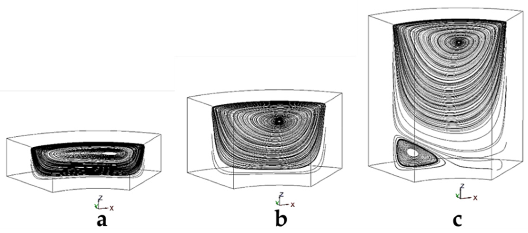
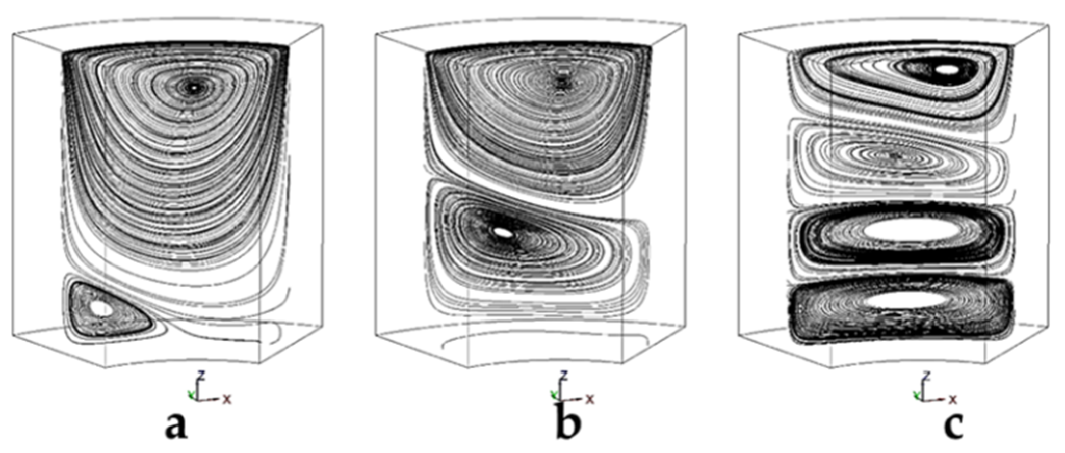
Figure 3 shows the streamlines in the cylindrical cavity for different aspect ratios.
Figure 3a shows the streamline in the cavity with a height ratio of 0.5. In this case, one vortex was made in the middle plane and the center of this vortex tends to the right side. The density of lines is higher which shows that the mass flow rate and velocity in this cavity should be higher due to the smaller size. The streamlines of the middle plane are shown for a height ratio of 1 in
Figure 3b. Still, one vortex is made in the middle plane, but the center of this vortex tends to the center of the cavity.
Figure 3c shows the streamlines of a cylindrical cavity with a height ratio of 2. This extra space allows the flow to make one large vortex and a small vortex at the left corner of the cavity. The density of lines is lower in comparison to the left figure which shows the velocity in this case is lower. It is evident that the flow in the middle plane is still two dimensional at the Reynolds 100.
Streamlines for different Rayleigh numbers are shown in
Figure 4. For all cases, the Reynolds number is equal to 100, the nanoparticle concentration is zero percent and the height ratio is 2. For the Ra = 10
4 (See
Figure 4a), there is just a large vortex in the cavity and a small vortex at the left corner. As the Rayleigh number increases to 10
5, the buoyant force can push up the large vortex and make more space for another vortex which direction of rotation is against the first vortex. By reaching to Ra = 10
6, the buoyancy force becomes more dominant and it can make a flow similar to Taylor-Couette flow. In this case, we have four vortices rotating against each other pair wisely. Increasing the Rayleigh number to more than 10
6 makes the flow turbulent and it can make many vortices in the flow.
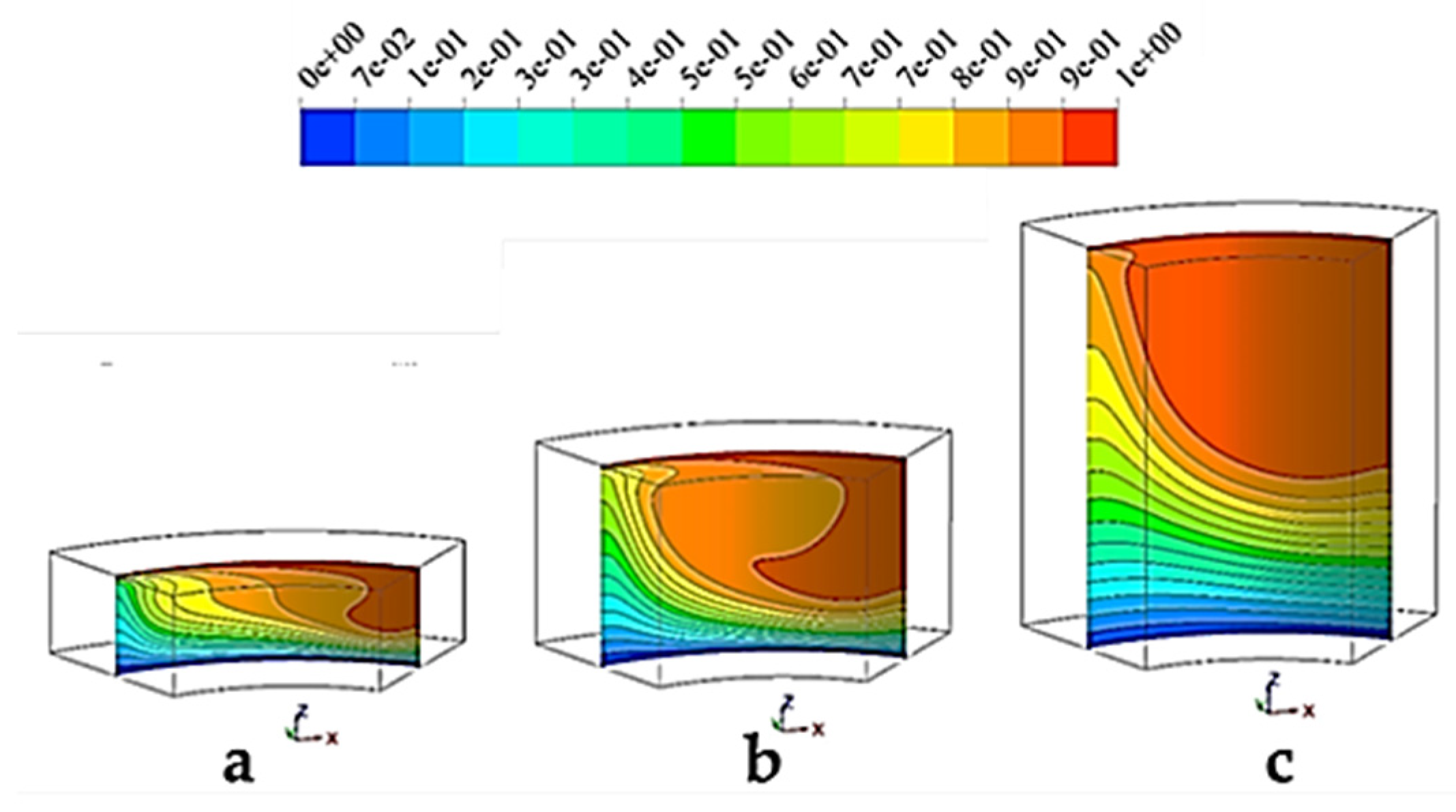
Figure 5 depicts isotherm lines in the cylindrical cavity for different height ratio. For HR = 0.5 (
Figure 5a), the temperature gradient is high, and it is made due to small vortex made in the middle of the cavity that has higher velocities. As the vortex becomes larger, the distribution changes and a hot region forms at the center of the cavity. Comparing it with streamlines in
Figure 3, reveals that this region is the core of that vortex. For HR = 2, the vortex makes a big hot region in the middle of the cavity and the temperature at the middle of the cavity is higher than the other height ratios. In addition, the temperature gradient at the bottom of the cavity is milder since the velocity at the bottom of the large cylinder is lower than other cylinders.
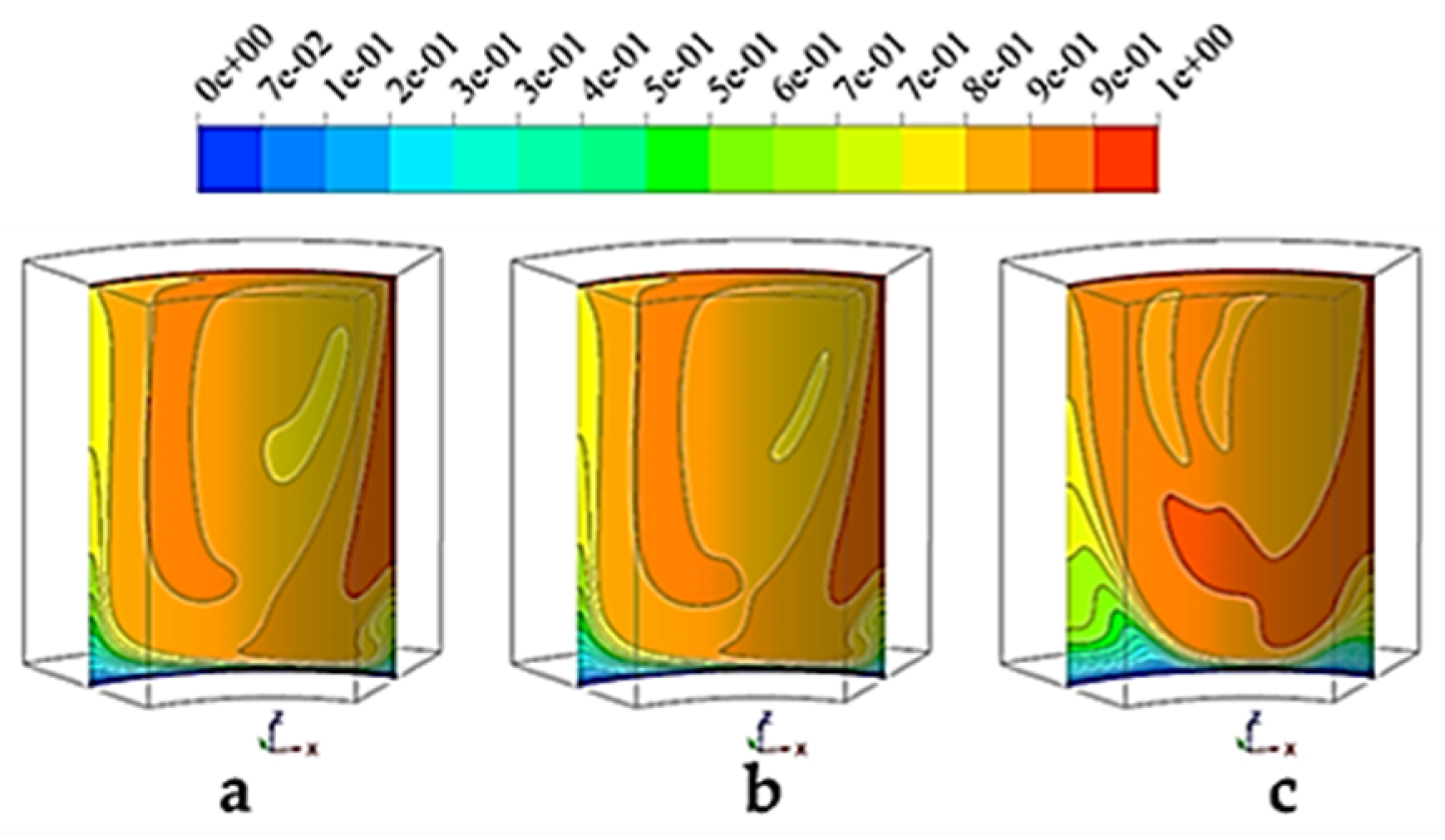
Figure 6 presents the distribution of temperature in the midplane of the cylindrical cavity. At the left and center, the cylinder contains zero and one percent of nano-particles; adding the one percent of nano-particles to the base fluid cannot influence the isotherm lines and the differences are ignorable. However, for the 5% mixture, there is a high temperature zone at the middle of the cavity which shows that the nanofluid brings more heat to the middle sections due to the change in properties.
Figure 7,
Figure 8 and
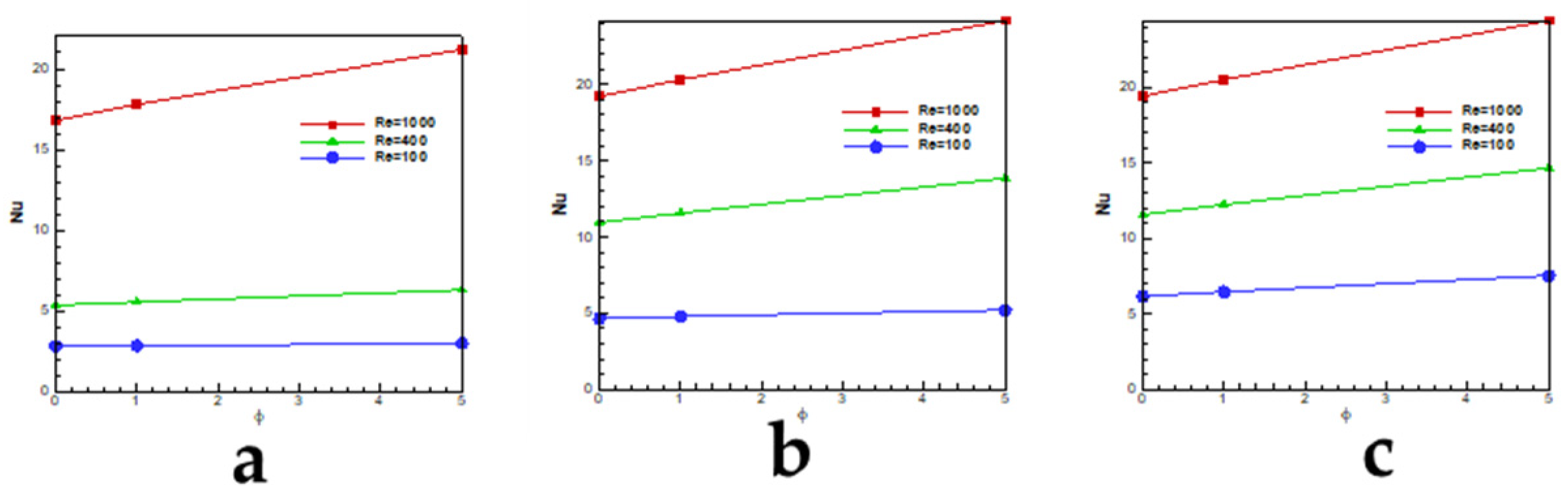
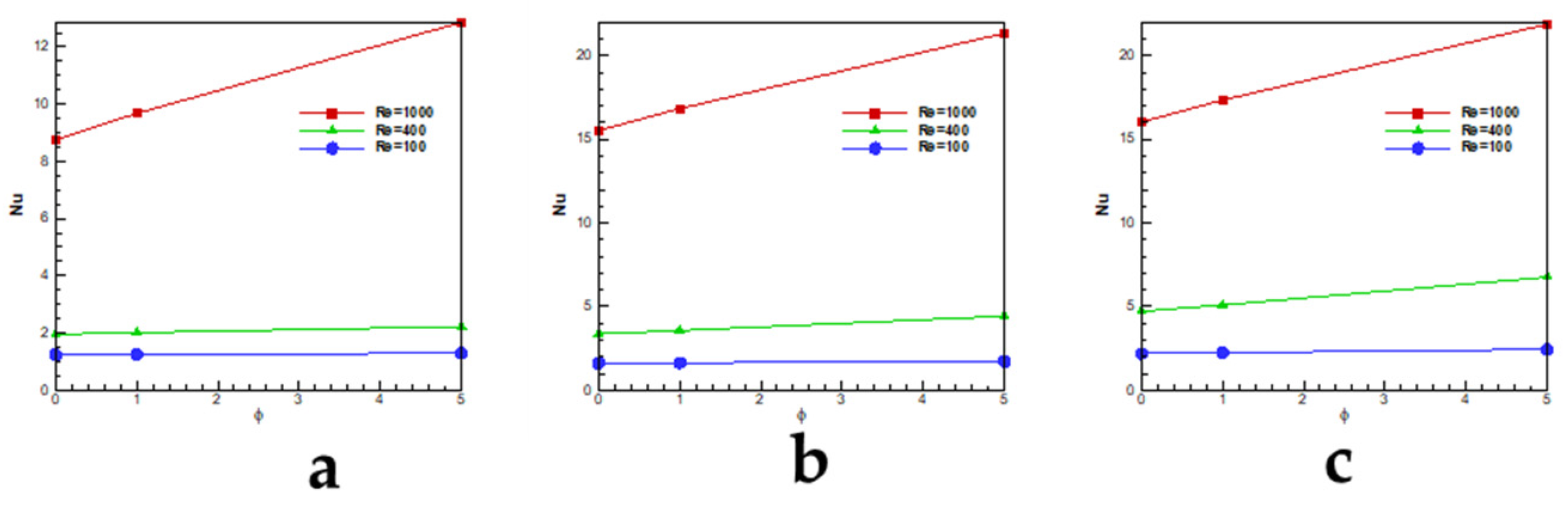
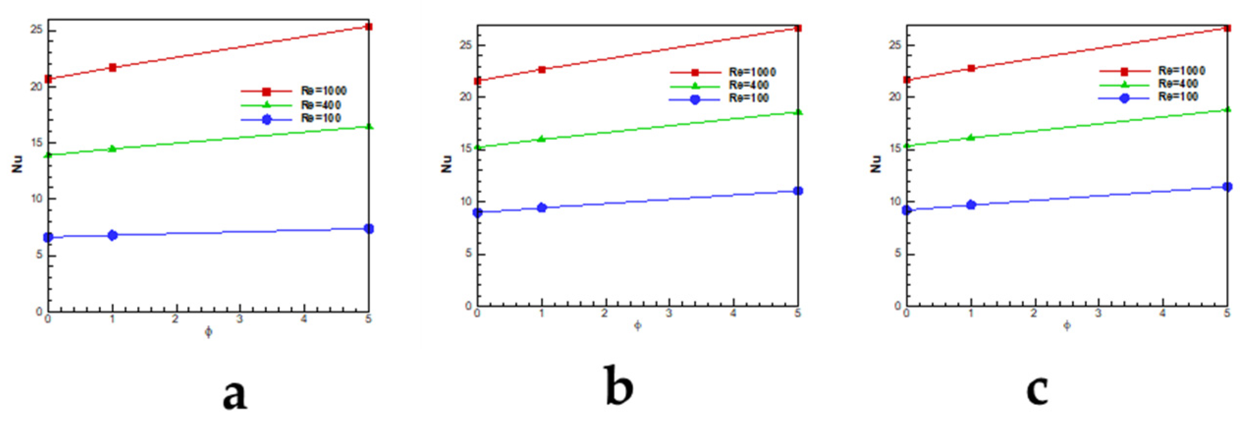
Figure 9 depicts the averaged Nusselt number on the top of the wall of lid-driven cylindrical cavity.
Figure 7 shows the Nusselt number for the aspect ratio, HR = 1. For Ra = 10
4 and low Reynolds numbers, the Nusselt number is almost a straight line but for the high Reynolds (10
3), the Nusselt number increases as the concentration of nano-particles increases in the fluid and still, the growth rate is linear. At Ra = 10
5, the Nusselt number does not increase by concentration change for Re = 100 but for Re = 400 and 1000, the increase of concentration helps to increase the Nusselt number. At Ra = 10
6, the concentration of nano-particles affects Nusselt numbers for all Reynolds numbers. For the case with HR = 0.5, as all curves show, the Nusselt number is affected by the change of nano particle concentrations. The change in Nusselt number for the Reynolds number is about 6% when the concentration changes from 0% to 5%. This value for the high Reynolds number (Re = 1000) reaches to 25%.
Figure 9 presents the values of Nusselt number for the cavity with the aspect ratio of 2. Compare to the other aspect ratios, the Nusselt values decrease due to the bigger space between the bottom and the top wall. The change of Nusselt values for the Re = 100 is about 4% although this change for higher Reynolds reaches to 46%. By comparing Nusselt values for different aspect ratios, it can be concluded that when the Rayleigh or aspect ratio increases, the nano-particles becomes more effective. The reason is that the nano-particles enhance the heat capacity of the nanofluid mixture more than other parameters like density, viscosity or conductivity and for the high Re flow, the effect of advection terms are more than diffusion terms which helps to increase heat transfer in the flow.


