Maximum Power Point Tracking for Photovoltaic System by Using Fuzzy Neural Network


 and
and 
Abstract
1. Introduction
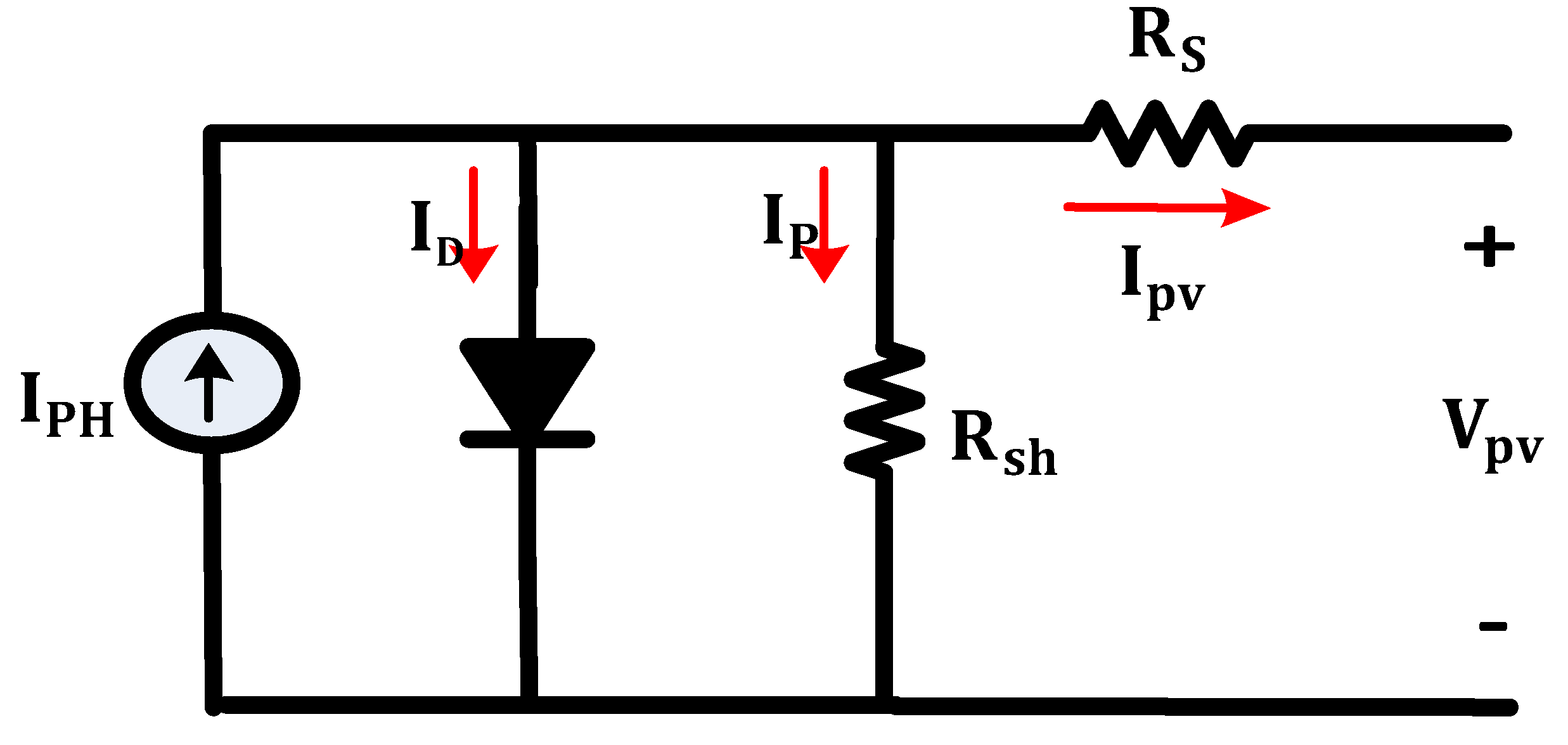
2. PV Modelling
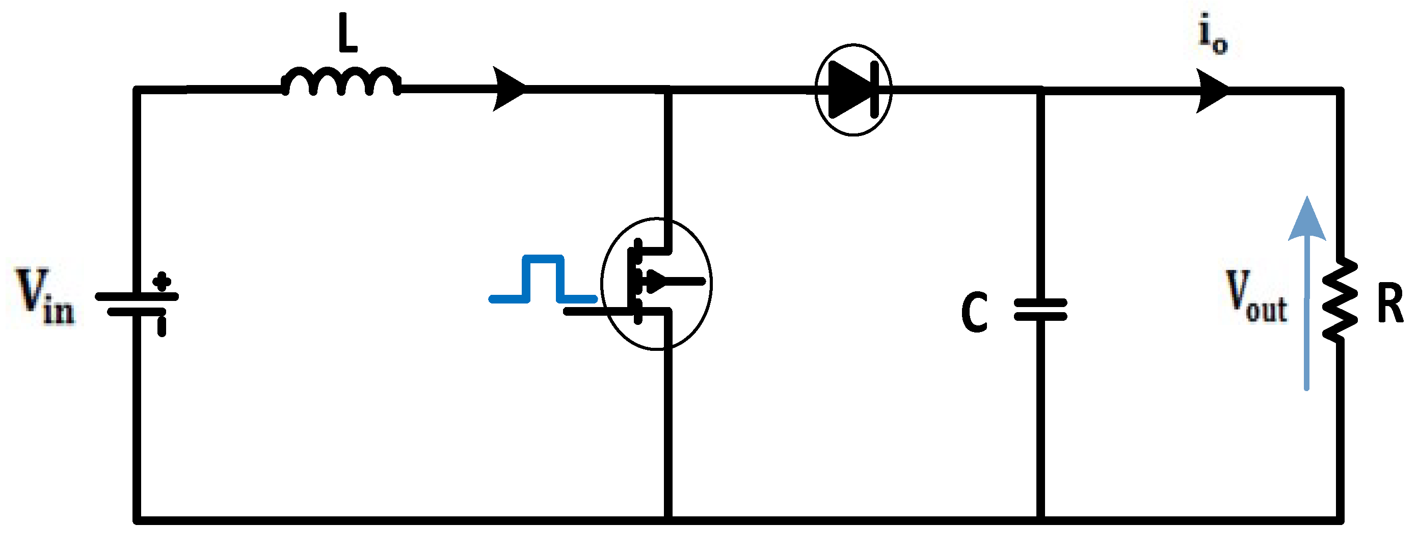
3. Boost Converter
4. MPPT Technique
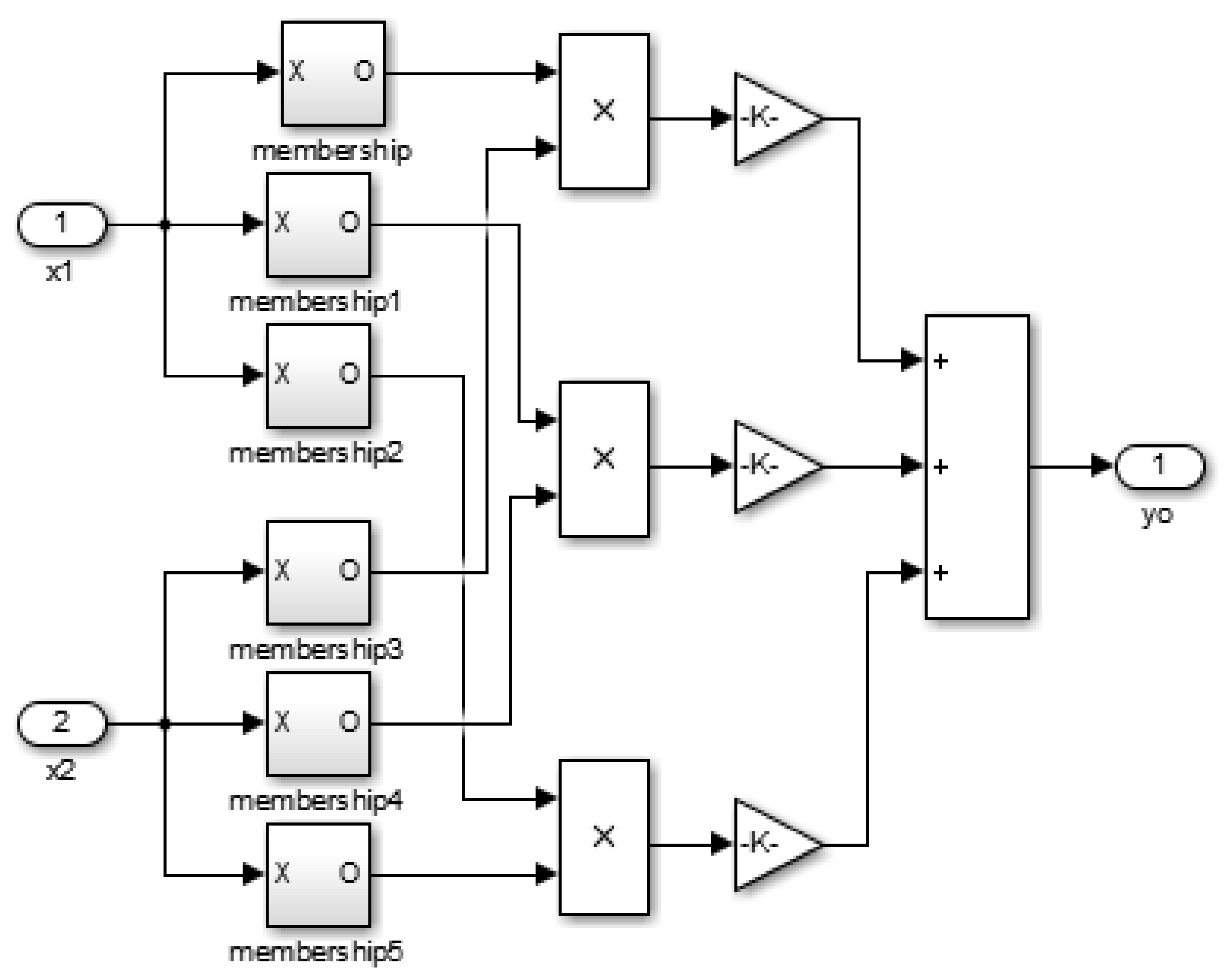
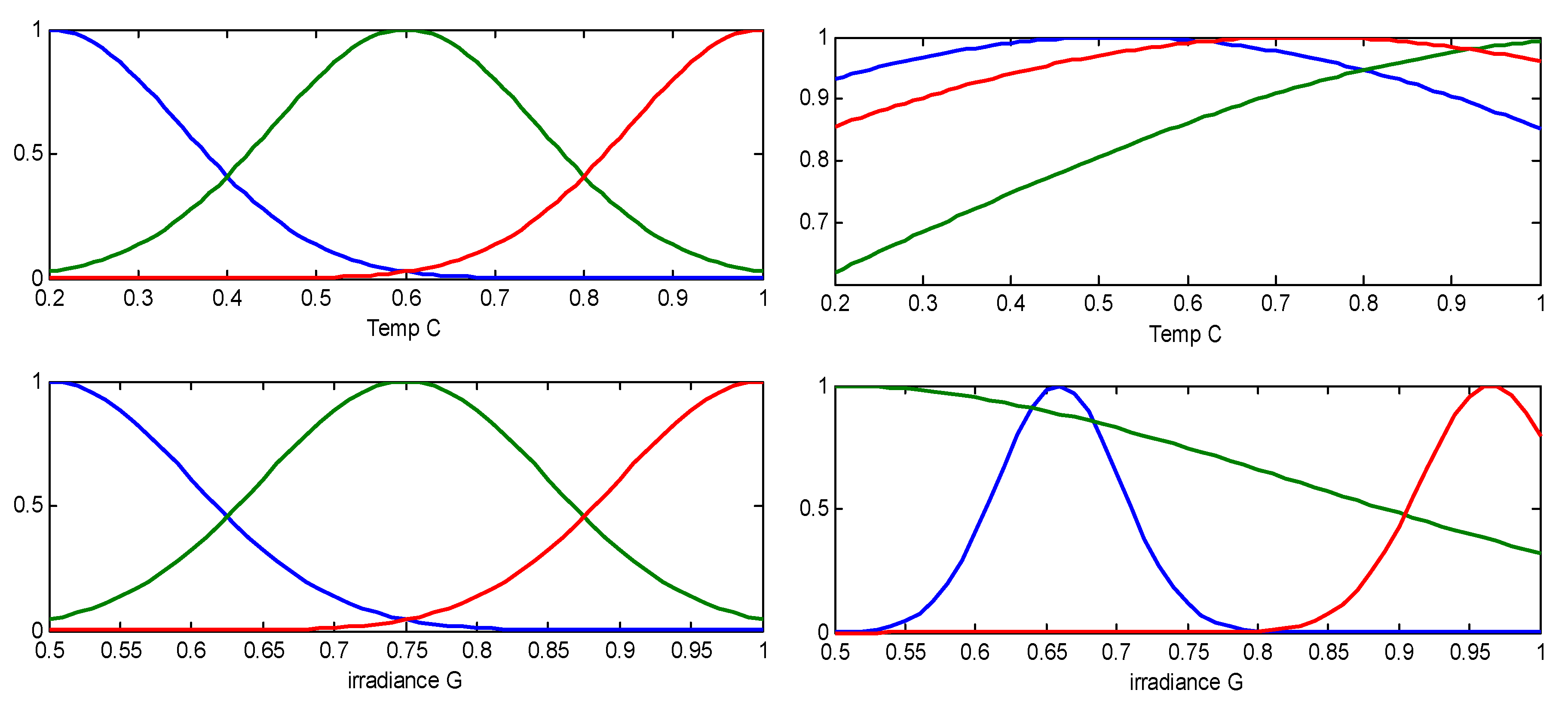
4.1. Fuzzy Neural Network (FNN) Controller
4.2. Learning Algorithm for the FNN Controller
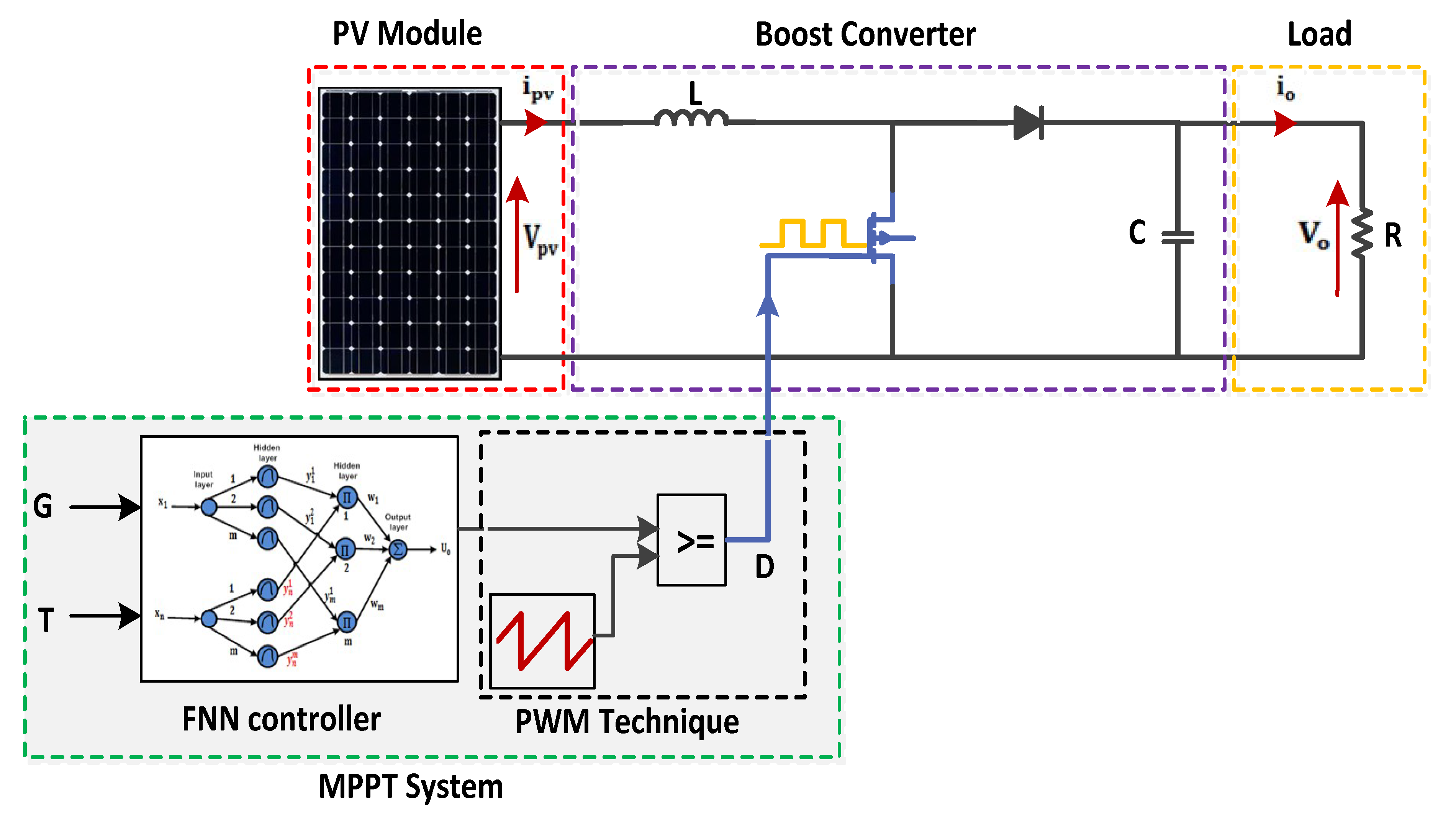
5. FNN Controller Based on Maximum Power Point Tracking (MPPT) for the Photovoltaic (PV) System
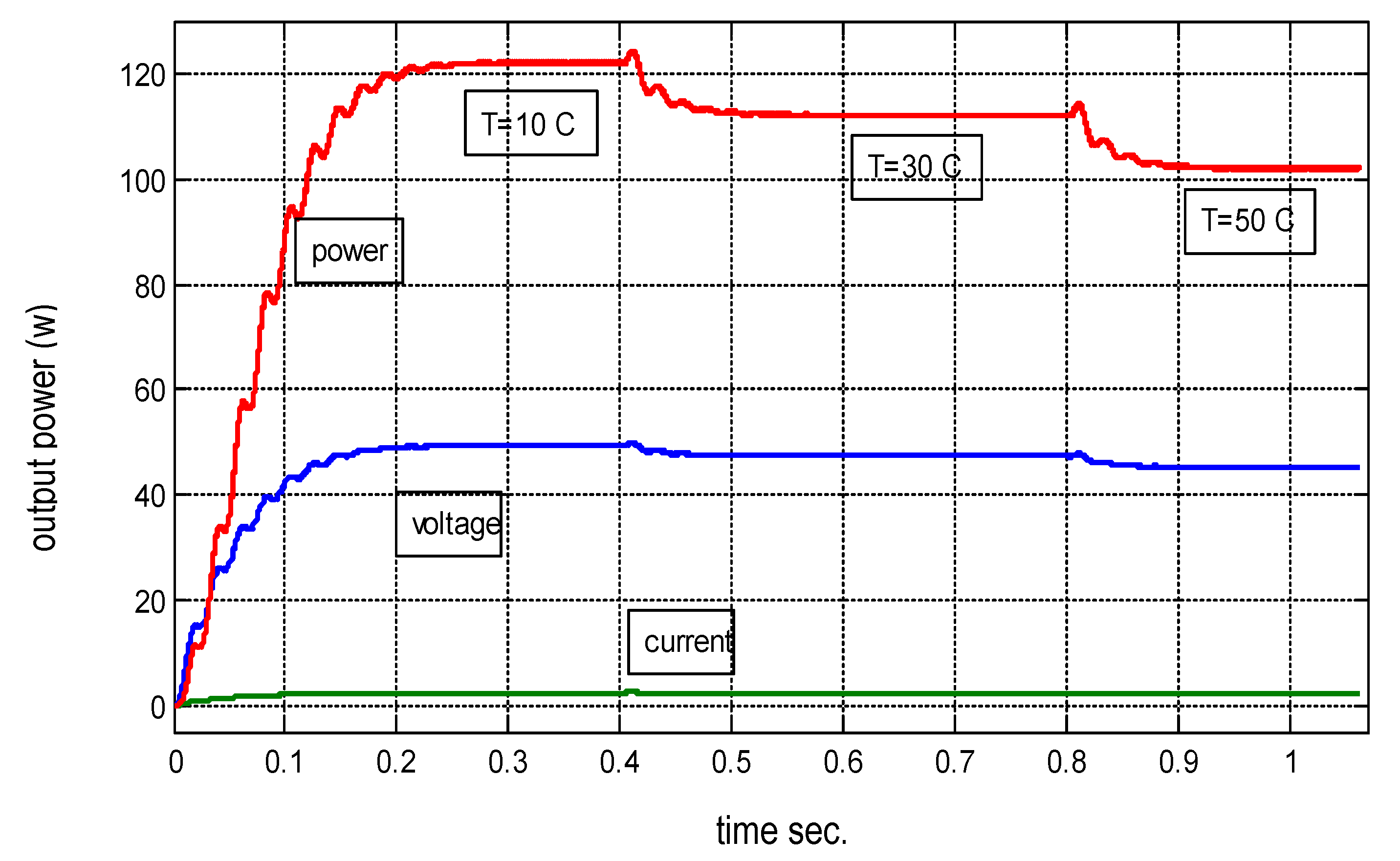
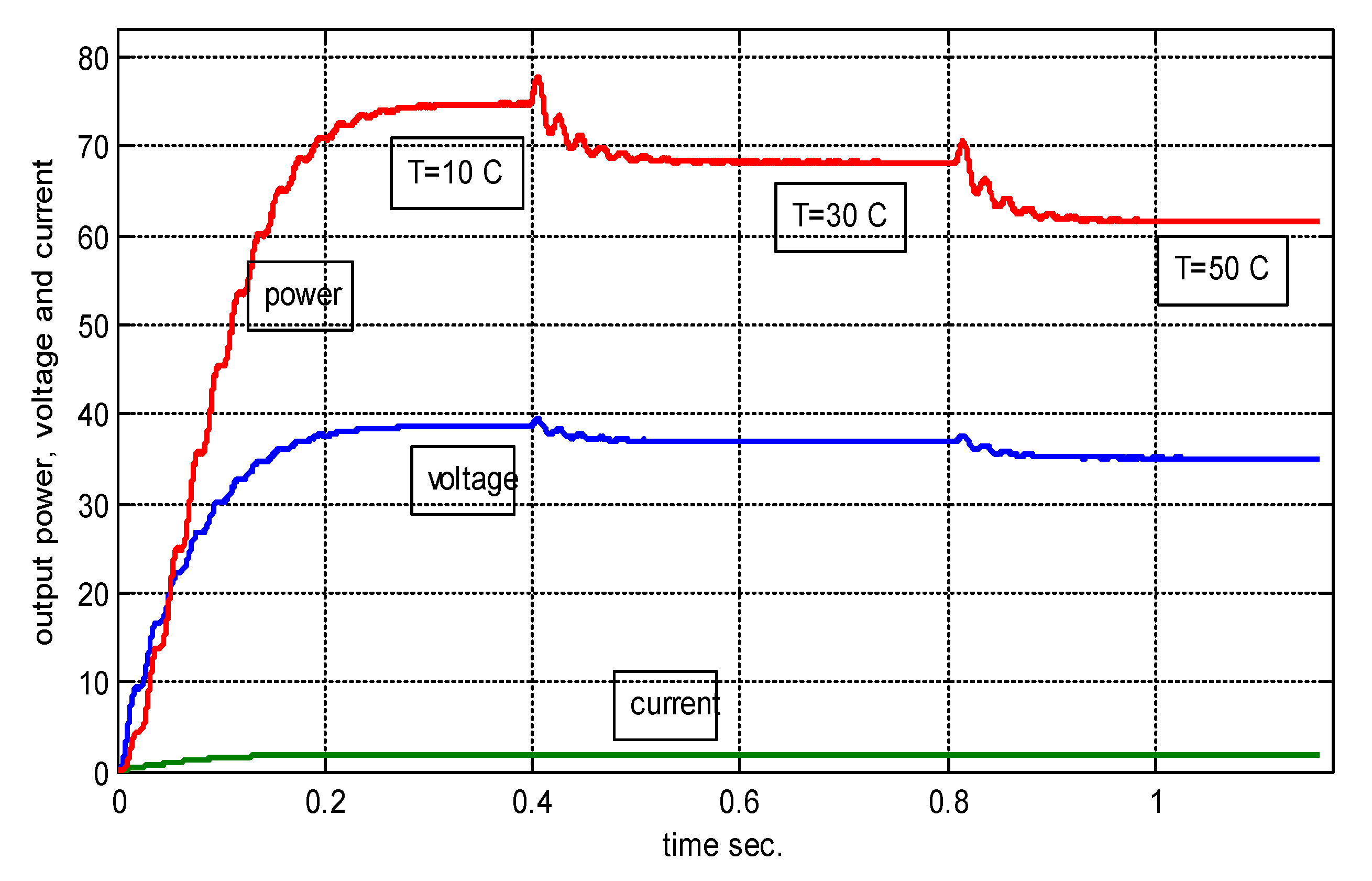
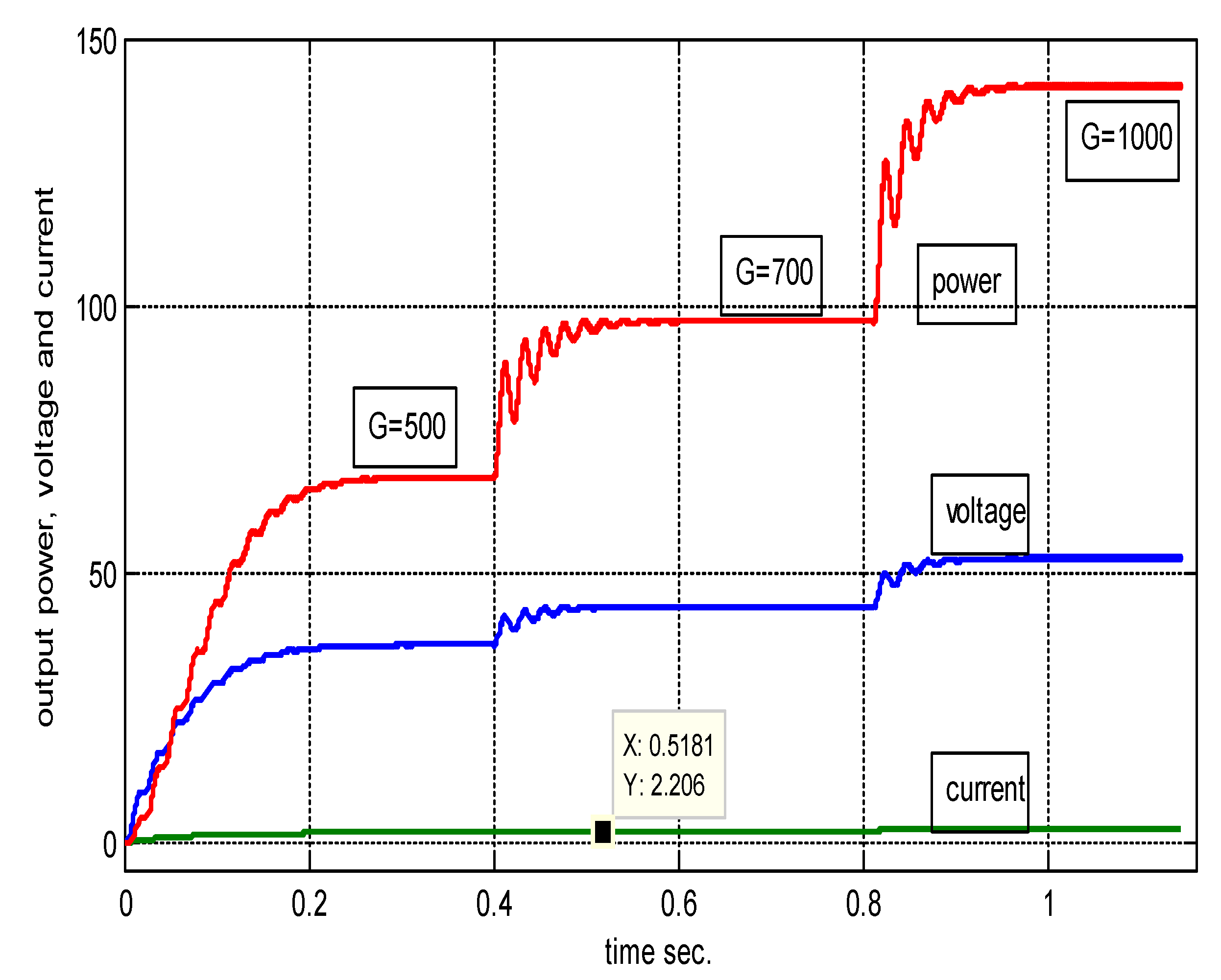
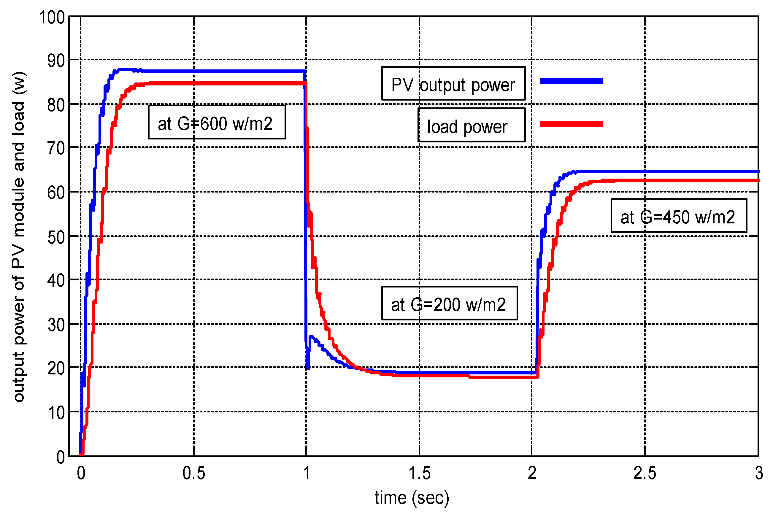
6. Simulation Results
7. Conclusions
Author Contributions
Funding
Conflicts of Interest
References
- Afef, B.; Mohamed, H.B.; Mohamed, N.M. A Comparison of Global MPPT Techniques for Partially Shaded Grid-connected Photovoltaic System. Int. J. Renew. Energy Res. 2018, 8, 1442–1452. [Google Scholar]
- Praful, R.M.; Ann, M.J. Design, Implementation and Performance Analysis of a LabVIEW based Fuzzy Logic MPPT Controller for Stand-Alone PV Systems. In Proceedings of the IEEE International Conference on Power, Control, Signals and Instrumentation Engineering (ICPCSI-2017), Chennai, India, 21–22 September 2017. [Google Scholar]
- Mohamed, A.E.; Zhengming, Z. MPPT techniques for photovoltaic applications. Renew. Sustain. Energy Rev. 2013, 25, 793–813. [Google Scholar]
- Kashif, I.; Zainal, S. A review of maximum power point tracking techniques of PV system for uniform insolation and partial shading condition. Renew. Sustain. Energy Rev 2013, 19, 475–488. [Google Scholar]
- Vinay, P.; Manju, A.M. Modelling and Analysis of Artificial Intelligence Based MPPT Techniques for PV Applications. In Proceedings of the International Conference on Advances in Green Energy (ICAGE), Trivandrum, India, 17–18 December 2014. [Google Scholar]
- Ounnas, D.; Ramdani, M.; Chenikher, S.; Bouktir, T. An Efficient Maximum Power Point Tracking Controller for Photovoltaic Systems Using Takagi–Sugeno Fuzzy Models. Arab. J. Sci. Eng. 2017, 42, 4971–4982. [Google Scholar] [CrossRef]
- Mahdi, H. Improving Efficiency of Photovoltaic System by Using Neural Network MPPT and Predictive Control of Converter. Int. J. Renew. Energy Res 2016, 6, 1524–1529. [Google Scholar]
- Mahlagha, M.; Li, L. An Adaptive Neuro-Fuzzy Controller for Maximum Power Point Tracking of Photovoltaic Systems. In Proceedings of the TENCON 2015—2015 IEEE Region 10 Conference, Macao, China, 1–4 November 2015. [Google Scholar]
- Ankit, G.; Pawan, K.; Rupendra, K.P.; Yogesh, K.C. Performance Analysis of Neural Network and Fuzzy Logic Based MPPT Techniques for Solar PV Systems. In Proceedings of the 2014 6th IEEE Power India International Conference (PIICON), Delhi, India, 5–7 December 2014. [Google Scholar]
- Mohammed, S.S.; Devaraj, D.; Ahamed, T.P. Maximum Power Point Tracking System for Stand Alone Solar PV Power System Using Adaptive Neuro-Fuzzy Inference System. Biennial International Conference on Power and Energy Systems: Towards Sustainable Energy (PESTSE). In Proceedings of the Biennial International Conference on Power and Energy Systems: Towards Sustainable Energy (PESTSE), Bangalore, India, 21–23 January 2016. [Google Scholar]
- Youssef, C.; Fatima, E.; Es-sbai, N. Design and verification of photovoltaic MPPT algorithm as an automotive based embedded software. Sol. Energy 2018, 171, 414–425. [Google Scholar]
- Doaa, M.A.; Hanaa, T.E. VHDL Based Maximum Power Point Tracking of Photovoltaic Using Fuzzy Logic Control. Int. J. Electr. Comput. Eng. (Ijece). 2017, 7, 3454–3466. [Google Scholar]
- Sadeq, D.A.; Maysam, F.A.; Hamed, S.A. A novel maximum power point tracking technique based on fuzzy logic for photovoltaic systems. Int. J. Hydrog. Energy 2018, 43, 14158–14171. [Google Scholar]
- Waleed, I.H.; Baha, A.S.; Ali, M.F. Voltage Tracking Control of DC-DC Boost Converter Using Fuzzy Neural Network. Int. J. Power Electron. Drive Syst. 2018, 9, 1657–1665. [Google Scholar]
- Su, H.; Bian, J. Maximum Power Point Tracking Algorithm Based On Fuzzy Neural Networks For Photovoltaic Generation System. In Proceedings of the International Conference on Computer Application and System Modeling (ICCASM 2010), Taiyuan, China, 22–24 October 2010. [Google Scholar]
- Hung-Ching, L.; Te-Lung, S. Design of DC/DC Boost Converter with FNN Solar Cell Maximum Power Point Tracking Controller. In Proceedings of the 5th IEEE Conference on Industrial Electronics and Applications, Taichung, Taiwan, 15–17 June 2010. [Google Scholar]
- Amara, K.; Fekik, A.; Hocine, D.; Bakir, M.L.; Bourennane, E.-B.; Malek, T.A.; Malek, A. Improved Performance of a PV Solar Panel with Adaptive Neuro Fuzzy Inference System ANFIS based MPPT. In Proceedings of the 7th International Conference on Renewable Energy Research and Applications (ICRERA), Paris, France, 14–17 October 2018. [Google Scholar]
- Hassan, S.Z.; Li, H.; Kamal, T.; Arifoğlu, U.; Mumtaz, S.; Khan, L. Neuro-Fuzzy Wavelet Based Adaptive MPPT Algorithm for Photovoltaic Systems. Energies 2017, 10, 394. [Google Scholar] [CrossRef]
- Khearia, A.M. Fuzzy Neural Controller for Multi-Machine Induction Motor Drives. Ph.D. Thesis, Electrical Engineering, Basrah University, Basra, Iraq, February 2009. [Google Scholar]


| 150 W | |
| Voltage at ( | 34.5 V |
| Current at | 4.35 A |
| Open circuit voltage () | 43.5 V |
| Short circuit current () | 4.75 A |
| Temperature coefficient of | 0.065 ± 0.015%/°C |
| Temperature coefficient of | −160 ± 20 mV%/°C |
| G(W/m2) | with MPPT | Voltage (V) | Current (A) | Efficiency with MPPT | Po(W) without MPPT | Efficiency without MPPT | T (°C) | |
|---|---|---|---|---|---|---|---|---|
| 800 | 126.3 | 122.1 | 49.4 | 2.47 | 96% | 87.7 | 69% | 10 |
| 116.2 | 112 | 47.3 | 2.36 | 96% | 76.8 | 66% | 30 | |
| 106 | 102 | 45.1 | 2.25 | 96% | 66.5 | 62% | 50 | |
| 500 | 77.15 | 74.5 | 38.6 | 1.93 | 96% | 69 | 89% | 10 |
| 70.5 | 68 | 36.8 | 1.84 | 96% | 62.5 | 88% | 30 | |
| 63.9 | 61.4 | 35 | 1.75 | 96% | 55.4 | 86% | 50 |
| G(W/m2) | Power (w) | Voltage (V) | Current (A) |
|---|---|---|---|
| 500 | 68 | 35.4 | 1.92 |
| 700 | 97 | 44 | 2.2 |
| 1000 | 141 | 52.2 | 2.7 |
© 2019 by the authors. Licensee MDPI, Basel, Switzerland. This article is an open access article distributed under the terms and conditions of the Creative Commons Attribution (CC BY) license (http://creativecommons.org/licenses/by/4.0/).
Share and Cite
Hameed, W.I.; Saleh, A.L.; Sawadi, B.A.; Al-Yasir, Y.I.A.; Abd-Alhameed, R.A. Maximum Power Point Tracking for Photovoltaic System by Using Fuzzy Neural Network. Inventions 2019, 4, 33. https://doi.org/10.3390/inventions4030033
Hameed WI, Saleh AL, Sawadi BA, Al-Yasir YIA, Abd-Alhameed RA. Maximum Power Point Tracking for Photovoltaic System by Using Fuzzy Neural Network. Inventions. 2019; 4(3):33. https://doi.org/10.3390/inventions4030033
Chicago/Turabian StyleHameed, Waleed I., Ameer L. Saleh, Baha A. Sawadi, Yasir I. A. Al-Yasir, and Raed A. Abd-Alhameed. 2019. "Maximum Power Point Tracking for Photovoltaic System by Using Fuzzy Neural Network" Inventions 4, no. 3: 33. https://doi.org/10.3390/inventions4030033
APA StyleHameed, W. I., Saleh, A. L., Sawadi, B. A., Al-Yasir, Y. I. A., & Abd-Alhameed, R. A. (2019). Maximum Power Point Tracking for Photovoltaic System by Using Fuzzy Neural Network. Inventions, 4(3), 33. https://doi.org/10.3390/inventions4030033