Article

Adaptive Control Synchronization of a Novel Memristive Chaotic System for Secure Communication Applications

by
Zain-Aldeen S. A. Rahman
1,
Hayder A. A. Al-Kashoash
1,
Saif Muneam Ramadhan
1 and
Yasir I. A. Al-Yasir
2,*
1
Technical Institute/Qurna, Southern Technical University, Basra 61016, Iraq
2
School of Electrical Engineering and Computer Science, Faculty of Engineering and Informatics, University of Bradford, Bradford BD7 1DP, UK
*
Author to whom correspondence should be addressed.
Inventions 2019, 4(2), 30; https://doi.org/10.3390/inventions4020030
Submission received: 2 May 2019 / Revised: 30 May 2019 / Accepted: 12 June 2019 / Published: 17 June 2019

Abstract

:
In this paper, a new memristive chaotic system is designed, analyzed, tested, and proposed. An adaptive control synchronization mechanism for both master and slave chaotic systems is also designed. The adaptive control law of this mechanism is derived based on the Lyapunov theory. A single parameter in the slave system has been assumed to be unknown. As the parameters of the master and slave are asymptotically matched, the unknown slave parameters will be identified according to the master’s parameters. The proposed system is used in a secure communication system. The achieved results prove a simple system implementation with a high security of data transmission.

1. Introduction

In recent years, the memristor device has been used as a fourth element in addition to the main three ones that construct electronic circuits. These three elements include the resistor, capacitor, and inductor. Chau proposed the fourth element [1,2], the memristor, which is described as an electronic element with two terminals. Williams’ group from HP laboratories realized the first memristor in 2008 [3,4].
The memristor element has a considerable effect in the characteristic of the electrical and electronic circuits; thus, it can play a significant role in the design of these circuits in the near future [5]. The memristor can be used in many applications, such as in signal processing, nonlinear oscillators design, adaptive control systems, and chaotic systems [6].
Moreover, the chaos schemes are considered as an essential topic in the research fields, as they can be used in many areas, such as in protected communication systems, intelligent systems, information processing, robotics manufacturing, control systems, and signal oscillators. In 1963, Lorenz found the first chaotic attractor [7,8]. Chaoticity occurrences can be generated by methods that include independent ordinary differential equations, which have a minimum of three variables with the term(s) producing the nonlinearity properties [9].
In chaos systems, the critical role for constructing secure communications schemes is the synchronization mechanism [10]. It can happen between two identical systems, of which one is a master and the driven one is a slave [11,12]. In the communication schemes, the master presents the transmitter side, and the slave shows the receiver side. The master derives the slave by the transmitted signals. Yamada and Fujisaka did the first study of chaotic synchronization research in 1983 [13].
Many chaos systems based on memristor schemes management have been established. Wang et al. [14] used the HP memristor model for proposing a simple chaotic signals oscillator. The proposed memristor model is designed for generating more composite pseudorandom signals depending on a flux-controlled memristive element that can create chaotic complex signals. Li et al. [15] designed and implemented a new chaotic circuit based on the HP memristor system model. The developed system produces a chaos wealth to generate a variety of complex attractors by changing only one parameter. Moreover, Buscarino et al. [16] introduced a new chaotic oscillator-based HP memristor model; they produced new chaotic signals by using the HP memristor model. Pham et al. [17] suggested an adaptive synchronization scheme for a memristor hyper-chaotic system in which an adaptive control method is used for designing an anti-synchronization scheme for the memristor system. The Arduino microcontroller has also been used to implement and develop the chaotic memristor system as in [18]. More recently, in 2016, Zhulin et al. designed and simulated chaotic circuit-based memristor circuits, as detailed in [19].
In this work, a new memristor element based on a sinusoidal function is proposed. The proposed new memristor element is used with a traditional chaotic system from the jerk systems family, confirming a new memristive chaotic scheme. By inserting the memristor, we can extend the three-dimensional chaotic system to four dimensions. The increase in the dimensionality has implications for designing better secure communication systems. A higher dimensional chaotic system has been used rather than a low-dimensional chaos system because it has more parameters and more complex attractors than a regular chaotic system, which makes the system highly secure in data transmission. There are many chaos-based communication schemes which have been proposed and studied in recent years. Chaotic masking is one of these methods and exists in the literature, as in [20,21].
The synchronization mechanism was developed between two identical chaotic schemes, one presented as the master and the other present as the slave. The control law was designed by an adaptive control method for updating the uncertain parameter on the slave side with respect to the master side. This scenario achieves an adaptive synchronization mechanism. Additionally, a secure communication scheme is suggested as an application for the proposed system and its synchronization. The achieved results were tested and determined by using Matlab Simulink.
The organization of this paper is as follows: In Section 2, the novel memristive model is proposed, and its parameters and the hysteresis loop are determined. In Section 3, we analyze the proposed new memristive chaotic system and determine its equilibrium points, eigenvalues, and its bifurcation diagram. In Section 4, the synchronization mechanism of two identical systems for the proposed memristive chaotic system is determined, the updating law of the parameter estimation is derived, and the synchronization mechanism is numerically simulated in this section. In Section 5, the suggested memristive chaotic system and the synchronization method are tested by encrypting a stream of binary numbers on the master side and decrypting this stream of binary numbers on the slave side. In Section 6, we conclude this paper.

2. Memristive Model

Generally, electronic circuit constructions contain three fundamental elements, which are the resistor, the inductor, and the capacitor [22]. In addition to that, the fourth circuit component was proposed theoretically by Chau in 1971 and was experimentally established in 2008 by HP laboratories [23]; this element is called a memristor. It has a nonlinear behavior such that it provides new functions in the electronic circuit designs [24,25]. The memristor represents the relationship between the charge and the flux, which is considered in the key variables of the model [26]. A memristive system can be described by Equation (1).
x ˙ = F ( x , u , t ) y = G ( x , u , t ) u
where y and u represent the input states of the memristive system, and x represents the output state. The functions F and G represent the vectors of the continuous n dimensions and scalar functions, respectively [27].
In this work, a novel memristive device is proposed, which is described by Equation (2).
x ˙ 1 = k x h ( x ,   x 1 ) = x x 1 ( c o s h 2 ( x 1 ) )
where x1 and x2 are the input and output states of the memristor scheme, respectively, in the memristor scheme, h(x, x1) describes the memristor output, where k is a positive parameter. Figure 1 depicts the hysteresis loop for the proposed new memristive element. This result is achieved by choosing k = 1 and the memristive deriving signal is a sinusoidal signal.

3. New Memristive Jerk System

A jerk system verifies a nonlinear function which is realized by the electronic circuit model [28]. Many scenarios in the field of engineering and physics can be described by jerk equations, such as mechanical oscillators, damped harmonic oscillators, and laser physics [29]. A simple chaotic jerk system can be obtained in a general form as a 3rd order ODE and is given in Equation (3).
d 3 z d t = J ( d 2 z d t , d z d t , z )
where J is the jerk function and is defined by a nonlinear function of the acceleration time derivation. The proposed new jerk system, based on the memristive system, is modeled by the dynamics Equation (4).
x ˙ = y y ˙ = z c h ( x ,   x 1 ) z ˙ = x b z + asinh ( y ) x ˙ 1 = k x
In Equation (4), x, x1, y, and z are the states, and a, b, and c are positive constant parameters for the system. The proposed system verifies the dynamics including the fixed (equilibrium) points, Lyapunov exponent, bifurcation, and chaoticity phenomena. For determining the equilibrium points of the proposed jerk system in Equation (4), the system is rearranged as in Equation (5).
x ˙ = y = 0 y ˙ = z c h ( x ,   x 1 ) = 0 z ˙ = x b z + asinh ( y ) = 0 x ˙ 1 = k x = 0
Therefore, this system has a single equilibrium point which is described by x = 0, x1 = 0, y = 0, and z = 0. At the equilibrium point E(0, 0, 0,0), and when the parameters a = 3.846 × 10⁻⁴, b = 0.7, c = 0.1, and k = 1, the Jacobian matrix can be obtained as in Equation (6).
J E = [ 0 1 0 0 0 0 1 0 1 a b 0 k 0 0 0 ]
Additionally, the system’s eigenvalues can be found according to Equation (7) [30].
| J e λ I | = λ 2 + b λ + ( 1 + a ) = 0
Therefore, the achieved eigenvalues of the proposed system are λ 1 = 0.35 + j 0.937 , λ 2 = 0.35 + j 0.937 ,   and   λ 3 = λ 4 = 0 , which prove that E(0, 0, 0, 0) is a saddle focus point.
The bifurcation diagrams can prove the nonlinear characteristics of the proposed system [31]. Bifurcation figures are generally used to show the behavior of chaotic systems [32]. Figure 2 illustrates the behavior of the system with respect to changes of the value of parameter b, where the parameter a = 3.846 × 10⁻⁴, c = 0.1, k = 1, and the initial conditions are (x(t0), x1(t0), y(t0), z(t0)) = (0, 0, 0.1, 0).
As seen in the bifurcation diagram, the proposed system verifies the normal chaotic performance for parameter b in the range of 0.4 ≤ b ≤ 0.9. Figure 3 shows the phase portraits in 2D and 3D forms, which were determined by Matlab Simulink. The numerical simulation results were determined by the parameters values: a = 3.846 × 10⁻⁴, b = 0.7, c = 0.1, and k = 1 with the initial conditions (x(t0), x1(t0), y(t0), z(t0)) = (0, 0.1, 0, 0).

4. Adaptive Synchronization

Using the chaos systems in communication schemes mainly depends on the synchronization between the transceivers [33]. Usually, according to the control law, a master-slave configuration is used in synchronization mechanisms in chaos systems [34]. By utilizing chaos theory in communication schemes, the master presents the transmitter side and the slave presents the receiver side. Many synchronization techniques can be used in the chaotic systems, as shown in [35,36]. Here, an adaptive synchronization technique with a single uncertain parameter was used for synchronizing two identical new memristive chaotic systems. In this section, we derive the adaptive control law for the synchronization mechanism.

4.1. Controller Design

The master and slave dynamics are presented by Equations (8) and (9), respectively:
x ˙ m = y m y ˙ m = z m c h m ( x ,   x 1 ) z ˙ m = x m b z m + a s i n h ( y m )
x ˙ s = y s + u 1 y ˙ s = z s c h s ( x ,   x 1 ) + u 2 z ˙ s = x s b z s + a s i n h ( y s ) + u 3
where ui(1,2,3) represent the feedback controllers to be designed. The synchronization errors can be assumed and given by Equation (10).
e 1 = x s x m e 2 = y s y m e 3 =   z s z m
Furthermore, the dynamic errors are determined by Equations (11)–(13).
ė 1 = y s + u 1 + y m = u 1 e 2
ė 2 = z s c h s ( x ,   x 1 ) + u 2 + z m + c h m ( x ,   x 1 ) = u 2 c h s ( x ,   x 1 ) + c h m ( x ,   x 1 ) e 3
ė 3 = x s b 2 ( t ) z s + a 1 sinh ( y s ) + u 3 + x m + b 1 z m a 1 sinh ( y m ) = e 1 b 2 ( t ) z s   +   b 1 z m + a 1 ( sinh ( y s ) sinh ( y m ) )   + u 3 = e 1 b 2 ( t ) ( e 3 + z m ) + b 1 z m + a 1 ( sinh ( y s ) sinh ( y m ) ) + u 3 =   e 1 b 2 ( t ) e 3 ( b 2 ( t ) b 1 ) z m + a 1 ( sinh ( y s ) sinh ( y m ) ) + u 3 = e 1 b 2 ( t ) e 2 e b ( t ) z m + a 1 ( sinh ( y s ) sinh ( y m ) ) + u 3
where the estimation error eb(t) of the master-slave parameters can be given by Equation (14), and b2(t) estimates parameter b1.
e b ( t ) = b 2 ( t ) b 1
Differentiating Equation (14) with respect to time leads to Equation (15).
ė b ( t ) = b ˙ 2 ( t )
For analyzing the stability of the dynamic errors, the Lyapunov function can be expressed as in Equation (16).
V ( t ) = 1 2 ( e 1 2 + e 2 2 + e 3 2 + e b 2 )
Then, by deriving Equation (16) with respect to time, Equation (17) can be expressed as:
d v d t =   ( e 1 e ˙ 1 +   e 2 e ˙ 2 +   e 3 e ˙ 3 + e b e ˙ b )
Substituting each derivative error in Equation (17) with its above value, Equation (18) can be obtained as:
d v d t = ( e 1 ( u 1 e 2 ) +   e 2 ( u 2 e 3 c h s ( x ,   x 1 ) + c h m ( x ,   x 1 ) ) +   e 3 ( e 1 b 2 ( t ) e 2 e b ( t ) z m + a 1 ( s i n h ( y s ) s i n h ( y m ) ) + u 3 ) +   ( b 2 ( t ) b 1 ) b ˙ 2 ( t ) )
Based on the Lyapunov stability theory [37,38], the feedback controllers can be obtained from Equation (18) as presented in Equation (19).
u 1 =   e 2 e 1 u 2   =   e 3   e 2 +   c h s ( x ,   x 1 ) c h m ( x ,   x 1 ) u 3 = e 1   +   b 2 ( t ) e 2     a 1 s i n h ( y s )
Furthermore, according to the Lyapunov stability theory and Equation (18), the updating law of the parameter estimation can be obtained as in Equation (20):
b ˙ 2 ( t ) = z m e 3

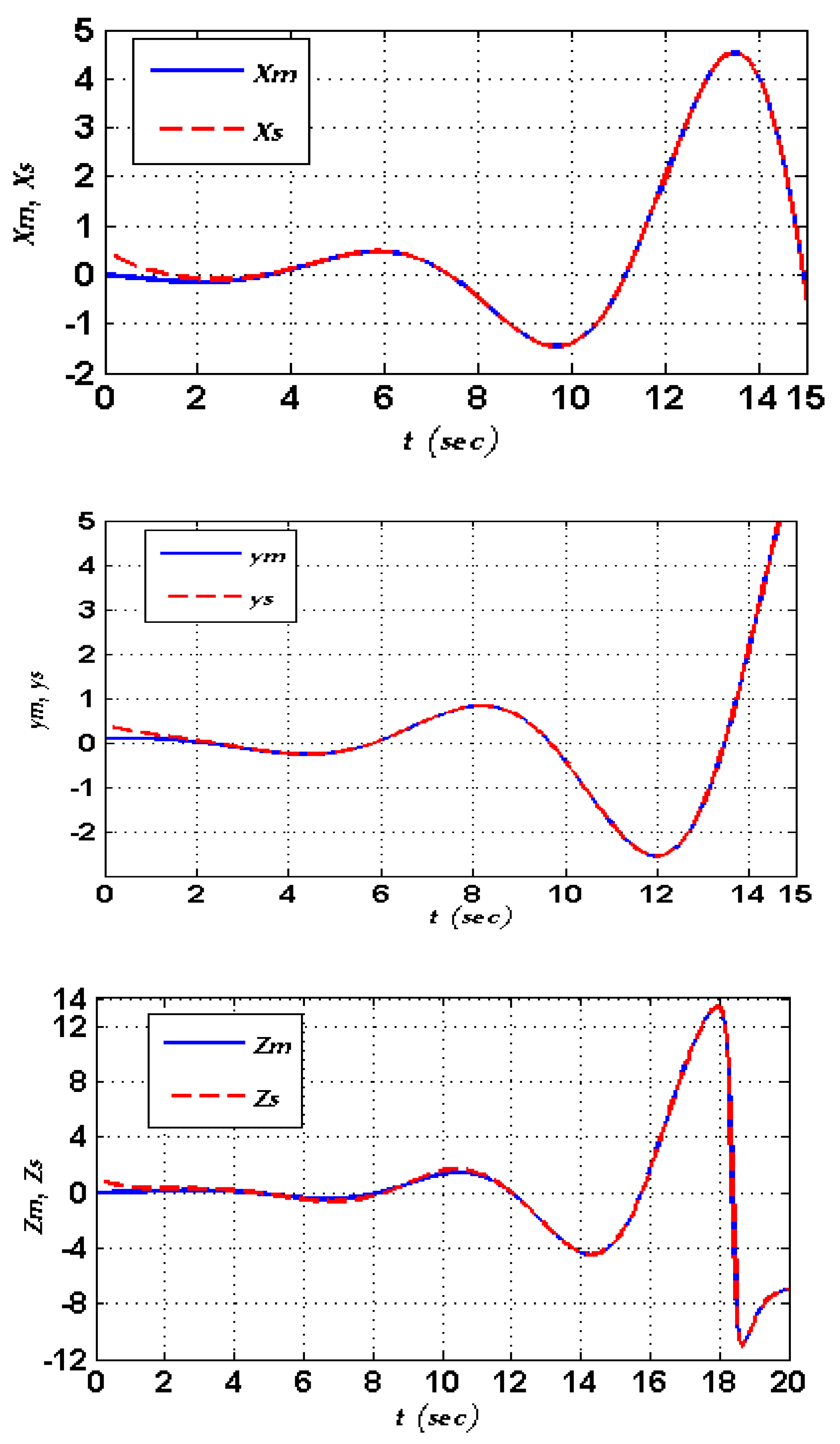
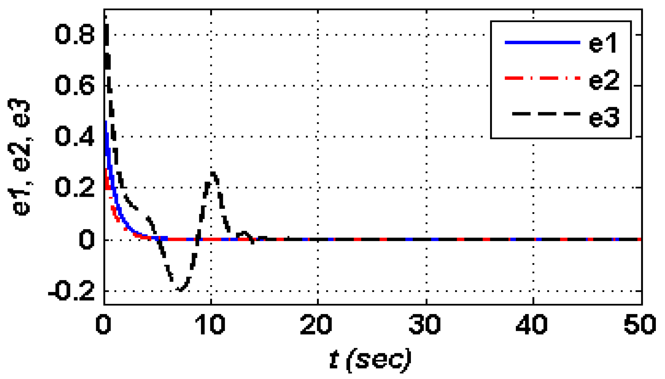
4.2. Numerical Simulation

To prove the feasibility and efficiency of the designed controller in the adaptive synchronization, Matlab software was used for simulating this synchronization mechanize. The simulation results were obtained for the master and slave parameters as shown in Table 1. The synchronization states and error of the master and slave are shown in Figure 4 and Figure 5, respectively. As seen in the above analysis for the updated law of the control design, the slave parameter b2(t) is the single uncertain parameter on the slave side. Figure 6 illustrates the convergence of the estimated slave parameter b2(t) to the master parameter value b1 = 0.7.

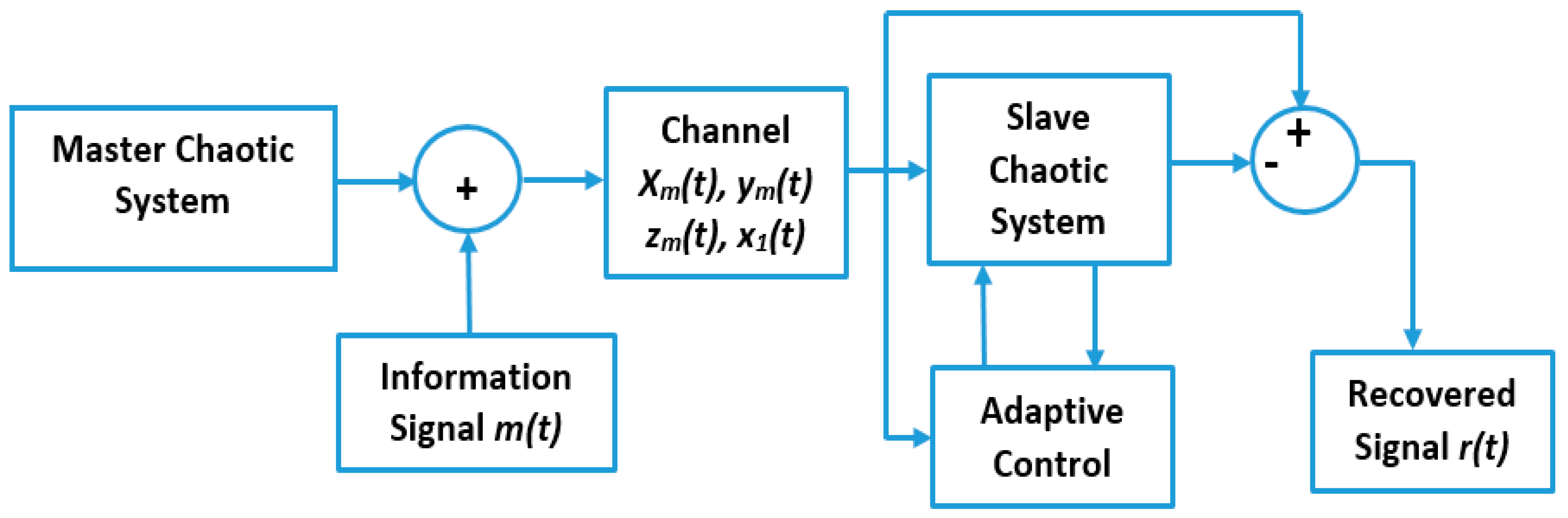
5. Application in Secure Communication

The purpose of the designed adaptive synchronization technique of the new memristive chaotic systems is to be used in secure communication schemes. The proposed communication scheme with an adaptive control synchronization mechanism is illustrated in Figure 7. On the master side, the required data signal is summed with the chaotic signals and transmitted at the same time. In this scenario, the determined data signal will be encoded by the chaotic signals. On the other hand, the receiver recovers the required data after removing the unwanted chaotic signal from the total received signal. In the simulation, the data signal m(t) is encoded by the output of chaotic signals ym on the master side as in Equation (21). Here, the data signal was a stream of binary numbers generated by a Bernoulli binary generator in Matlab Simulink as shown in Figure 8.
x ˙ = y + m ( t ) y ˙ = z c h ( x ,   x 1 ) z ˙ = x b z + a s i n h ( y )
On the transmitter side, the transmitted signal s(t) of the noiseless channel is given by Equation (22).
s ( t ) = y m ( t ) + m ( t )
On the receiver side, the required data signal r(t) can be recovered and obtained as in Equation (23). Figure 8 shows the signals of the proposed secure communication scheme.
r ( t ) = s ( t ) y s ( t )

6. Conclusions

In this work, a new memristor model was designed and tested. This memristor model was simulated and verified, and it showed a very good dynamic behavior. After proving the objective performance of that memristor model, it was integrated with a classical jerk chaotic system to produce a new memristive jerk chaotic system. Furthermore, a synchronization mechanism was designed for two identical chaotic schemes; one presents the master and the other presents the slave. An adaptive control method was used to develop the control law to synchronize and update the uncertainty parameter on the slave side according to the master side. Moreover, the proposed system was utilized to construct a secure communication system. Finally, the hysteresis loop of the proposed memristive system proved that the implementation of this model is very secure and very simple. Small margin changes of the memristive parameter led to significant effects in the output signal. The simulation results of the designed system were achieved by using Matlab-Simulink.

Author Contributions

Conceptualization, Z.-A.S.A.R.; methodology, Z.-A.S.A.R. and H.A.A.A.-K.; investigation, Z.-A.S.A.R., H.A.A.A.-K. and S.M.R.; resources, Z.-A.S.A.R., H.A.A.A.-K., S.M.R. and Y.I.A.A.-Y.; writing—original draft preparation, Z.-A.S.A.R., H.A.A.A.-K., S.M.R. and Y.I.A.A.-Y.; writing—review and editing, Y.I.A.A.-Y., H.A.A.A.-K., S.M.R. and Z.-A.S.A.R.; visualization, Y.I.A.A.-Y., Z.-A.S.A.R., S.M.R., and H.A.A.A.-K.

Funding

This research received no external funding.

Conflicts of Interest

The authors declare no conflict of interest.

References

  1. Chau, L. Memristor-The Missing Circuit Element. IEEE Trans. Circuit Theory 1971, 18, 507–519. [Google Scholar] [CrossRef]
  2. Chau, L.; Kang, S.M. Memristive Devices and Systems. Proc. IEEE 1976, 64, 209–223. [Google Scholar] [CrossRef]
  3. Strukov, D.B.; Snider, G.S.; Stewart, D.R.; Williams, R.S. The Missing Memristor Found. Nature 2008, 453, 80–83. [Google Scholar] [CrossRef] [PubMed]
  4. Ventra, M.D.; Pershin, Y.V.; Chua, L. Circuit elements with memory: Memristors, memcapacitors, and meminductors. Proc. IEEE 2009, 97, 1717–1724. [Google Scholar] [CrossRef]
  5. Bao, B.; Ma, Z.; Xu, J.; Liu, Z.; Xu, Q. A simple memristor chaotic circuit with complex dynamics. Int. J. Bifurc. Chaos 2011, 21, 2629–2645. [Google Scholar] [CrossRef]
  6. Wang, L.; Drakakis, E.; Duan, S.; He, P. Memristor model and its application for chaos generation. Int. J. Bifurc. Chaos 2012, 22, 1250205. [Google Scholar] [CrossRef]
  7. Pehlivan, I.; Glu, Y. A new chaotic attractor from general Lorenz system family and its electronic experimental implementation. Turk. J. Electr. Eng. Comp. Sci. 2010, 18, 171–184. [Google Scholar]
  8. Damei, L.; Junan, L.; Xiaoqun, W.; Guanrong, C. Estimating the ultimate bound and positively invariant set for the Lorenz system and a unified chaotic system. J. Math. Anal. Appl. 2006, 323, 844–853. [Google Scholar]
  9. Grigorenko, I.; Grigorenko, E. Chaotic Dynamics of the Fractional Lorenz System. Phys. Rev. Lett. 2003, 91, 034101. [Google Scholar] [CrossRef]
  10. Liao, T.; Tsai, S. Adaptive synchronization of chaotic systems and its application to secure communications. Chaos Solitons Fractals 2000, 11, 1387–1396. [Google Scholar] [CrossRef]
  11. L, L.Z.; Zheng, Z. Secure Communication Scheme with Hyper-Chaotic Lorenz-Stenflo System. In Proceedings of the 2011 International Conference on Electronics, Communications and Control (ICECC), Ningbo, China, 9–11 September 2011; pp. 1928–1931. [Google Scholar]
  12. Sergej, C.; Guanrong, C. Secure Synchronization of a Class of Chaotic Systems from a Nonlinear Observer Approach. IEEE Trans. Autom. Control 2005, 50, 76–82. [Google Scholar]
  13. Stefanskin, A.; Kapitaniak, T. Synchronization of two chaotic oscillators via a negative feedback mechanism. Int. J. Solids Struct. 2003, 40, 5175–5185. [Google Scholar] [CrossRef]
  14. Wang, G.; Cui, M.; Cai, M.; Wang, X.; Hu, T. A Chaotic Oscillator Based on HP Memristor Model. Math. Probl. Eng. 2015. [Google Scholar] [CrossRef]
  15. Li, H.; Wang, L.; Duan, S. A memristor-based scroll chaotic system-design, analysis and circuit implementation. Int. J. Bifurc. Chaos 2014, 24, 1–13. [Google Scholar] [CrossRef]
  16. Buscarino, A.; Fortuna, L.; Frasca, M.; Gambuzza, L. A chaotic circuit based on Hewlett-Packard memristor. Chaos Interdiscip. J. Nonlinear Sci. 2012, 22, 023136. [Google Scholar] [CrossRef] [PubMed]
  17. Pham, V.-T.; Volos, C.K.; Vaidyanathan, S.; Le, T.P.; Vu, V.Y. A Memristor Based Hyperchaotic System with Hidden Attractors: Dynamics, Synchronization and Circuital Emulating. J. Eng. Sci. Technol. Rev. 2015, 8, 205–214. [Google Scholar] [CrossRef]
  18. Yener, S.C.; Barbaros, C.; Mutlu, R.; Karakulak, E. Implementation of Microcontroller-Based Memristive Chaotic Circuit. Acta Phys. Pol. A 2017, 132, 1058–1061. [Google Scholar] [CrossRef]
  19. Zhulin, W.; Fuhong, M.; Guangya, P.; Yaoda, W.; Yi, C. Bifurcation and Chaos of the Memristor Circuit. Int. J. Comput. Inf. Eng. 2016, 10, 1976–1982. [Google Scholar]
  20. Pyvovar, O.S.; Polikarovskykh, O.I. A System of Secure Communication with Chaos Masking Based on Rucklidge Generators. In Proceedings of the 38th International Conference on Electronics and Nanotechnology (ELNANO), Kiev, Ukraine, 24–26 April 2018. [Google Scholar]
  21. Elkholy, M.M.; Hennawy, H.M.E.L.; Elkouny, A. Design and implementation of hyper chaotic masking system for secured audio transmission. In Proceedings of the 2015 Tenth International Conference on Computer Engineering & Systems (ICCES), Cairo, Egypt, 23–24 December 2015. [Google Scholar]
  22. Tahir, S.A. The synchronization of identical Memristors systems via Lyapunov direct method. Appl. Comput. Math. 2013, 2, 130–136. [Google Scholar] [CrossRef]
  23. Ma, J.; Chen, Z.; Wang, Z.; Zhang, Q. A four-wing hyper-chaotic attractor generated from a 4D memristive system with a line equilibrium. Nonlinear Dyn. 2015, 81, 1275–1288. [Google Scholar] [CrossRef]
  24. Kim, H.; Sah, M.; Yang, C.; Cho, S.; Chua, L. Memristor emulator for memristor circuit applications. IEEE Trans. Circuits Syst. I 2012, 59, 2422–2431. [Google Scholar]
  25. Corinto, F.; Forti, M. Memristor circuits: bifurcations without parameters. IEEE Trans. Circuits Syst. I 2017, 64, 1540–1551. [Google Scholar] [CrossRef]
  26. Junsangsri, P.; Lombardi, F. Design of a hybrid memory cell using memristance and ambipolarity. IEEE Trans. Nanotechnol. 2013, 12, 71–80. [Google Scholar] [CrossRef]
  27. Bao, B.; Jiang, P.; Wu, H.; Hu, F. Complex transient dynamics in periodically forced memristive Chua’s circuit. Nonlinear Dyn. 2015, 79, 2333–2343. [Google Scholar] [CrossRef]
  28. Pham, V.T.; Vaidyanathan, S.; Volos, C.K.; Jafari, S.; Kuznetsov, N.V.; Hoang, T.M. A Novel memristive time-delay chaotic system without equilibrium points. Eur. Phys. J. Spec. Top. 2016, 225, 127–136. [Google Scholar] [CrossRef]
  29. Mahmoud, G.M.; Ahmed, M.E. Chaotic and Hyperchaotic Complex Jerk Equations. Int. J. Mod. Nonlinear Theory Appl. 2012, 1, 6–13. [Google Scholar] [CrossRef] [Green Version]
  30. Sprott, J.C. Some simple chaotic jerk functions. Am. J. Phys. 1997, 65, 537–543. [Google Scholar] [CrossRef]
  31. Zhang, Y.; Wang, X.; Friedman, E.G. Memristor-Based circuit design for multilayer neural networks. IEEE Trans. Circuits Syst. I 2018, 65, 677–686. [Google Scholar] [CrossRef]
  32. Xu, J.; Cai, G.; Zheng, S. Adaptive Synchronization for an Uncertain New Hyperchaotic Lorenz System. Int. J. Nonlinear Sci. 2009, 8, 117–123. [Google Scholar]
  33. Lü, J.; Chen, G. A new chaotic attractor coined. Int. J. Bifurc. Chaos 2002, 12, 659–661. [Google Scholar] [CrossRef]
  34. Yang, T.; Chua, L. Impulsive stabilization for control and synchronization of chaotic systems: Theory and application to secure communication. IEEE Trans. Circuits Syst. I 1997, 44, 976–988. [Google Scholar] [CrossRef]
  35. Durdu, A.; Özcerit, A.T. A Novel Chaotic System for Secure Communication Applications. Inf. Technol. Control 2015, 44, 271–278. [Google Scholar] [CrossRef]
  36. Huang, T. Synchronization of Chaotic Systems with Time-Varying Coupling Delays. Discret. Contin. Dyn. Syst. Ser. B 2011, 16, 1071–1082. [Google Scholar] [CrossRef]
  37. Chen, S.; Lü, J. Synchronization of an uncertain unified chaotic system via adaptive control. Chaos. Solut. Fractals 2002, 14, 643–647. [Google Scholar] [CrossRef] [Green Version]
  38. Maheril, M.; Arifin, N.M. Application adaptive exponential synchronization of chaotic dynamical systems in secure communications. Adv. Differ. Equ. 2017. [Google Scholar] [CrossRef]
Figure 1. The memristive hysteresis loop: (a) x1(0) = 0, amplitude (A) of driven sinusoidal signal = 1, and different frequencies (f); (b) x1(0) = 0, frequency = 1, and different amplitudes. The memristive hysteresis loop (continued): (c) frequency = 1, amplitude = 1, and different initial conditions of x1(t).
Inventions 04 00030 g001
Figure 2. The bifurcation diagram of the proposed memristive chaotic systems.
Inventions 04 00030 g002
Figure 3. The phase portraits in 2D and 3D arrangements.
Inventions 04 00030 g003
Figure 4. States synchronization.
Inventions 04 00030 g004
Figure 5. Synchronization errors.
Inventions 04 00030 g005
Figure 6. Estimation of slave parameter b2(t).
Inventions 04 00030 g006
Figure 7. Proposed communication scheme.
Inventions 04 00030 g007
Figure 8. Signals of the proposed secure communication scheme.
Inventions 04 00030 g008
Table 1. Parameters of slave and master.
MasterSlave
ParameterValueParameterValue
a13.846 × 10−4a23.846 × 10−4
b10.7b2(t)uncertain
xm(t0)0xs(t0)0.5
ym(t0)0.1ys(t0)0.4
zm(t0)0zs(t0)1

