Ground-Coupled Natural Circulating Devices (Thermosiphons): A Review of Modeling, Experimental and Development Studies


Abstract
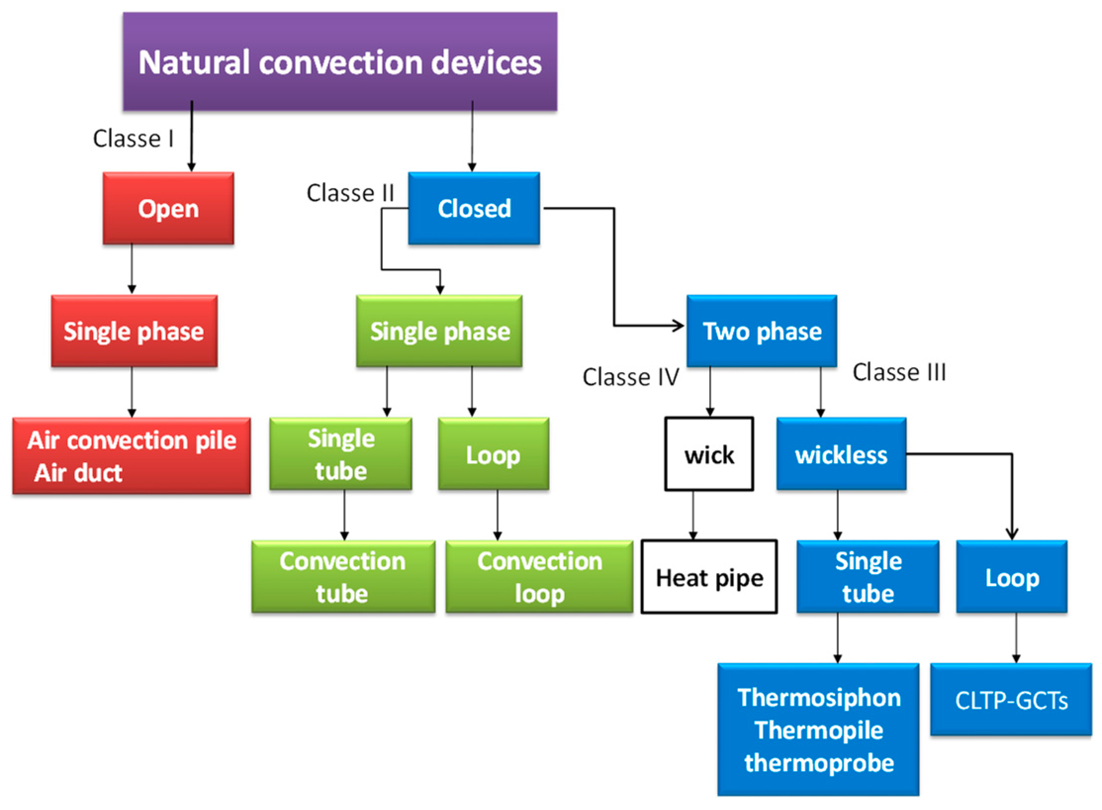
:1. Introduction
- Open, single phase, naturally circulating devices (red colour);
- Closed, single phase, naturally circulating devices (green colour);
- Wickless, closed, two-phase, naturally circulating devices (blue colour);
- Closed, two phase, devices with a Wick structure (white colour).
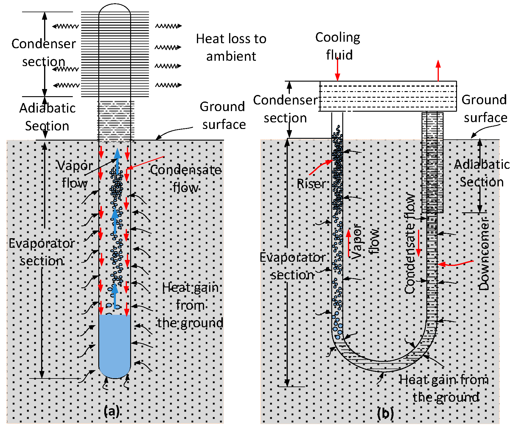
1.1. Operation of GCTs
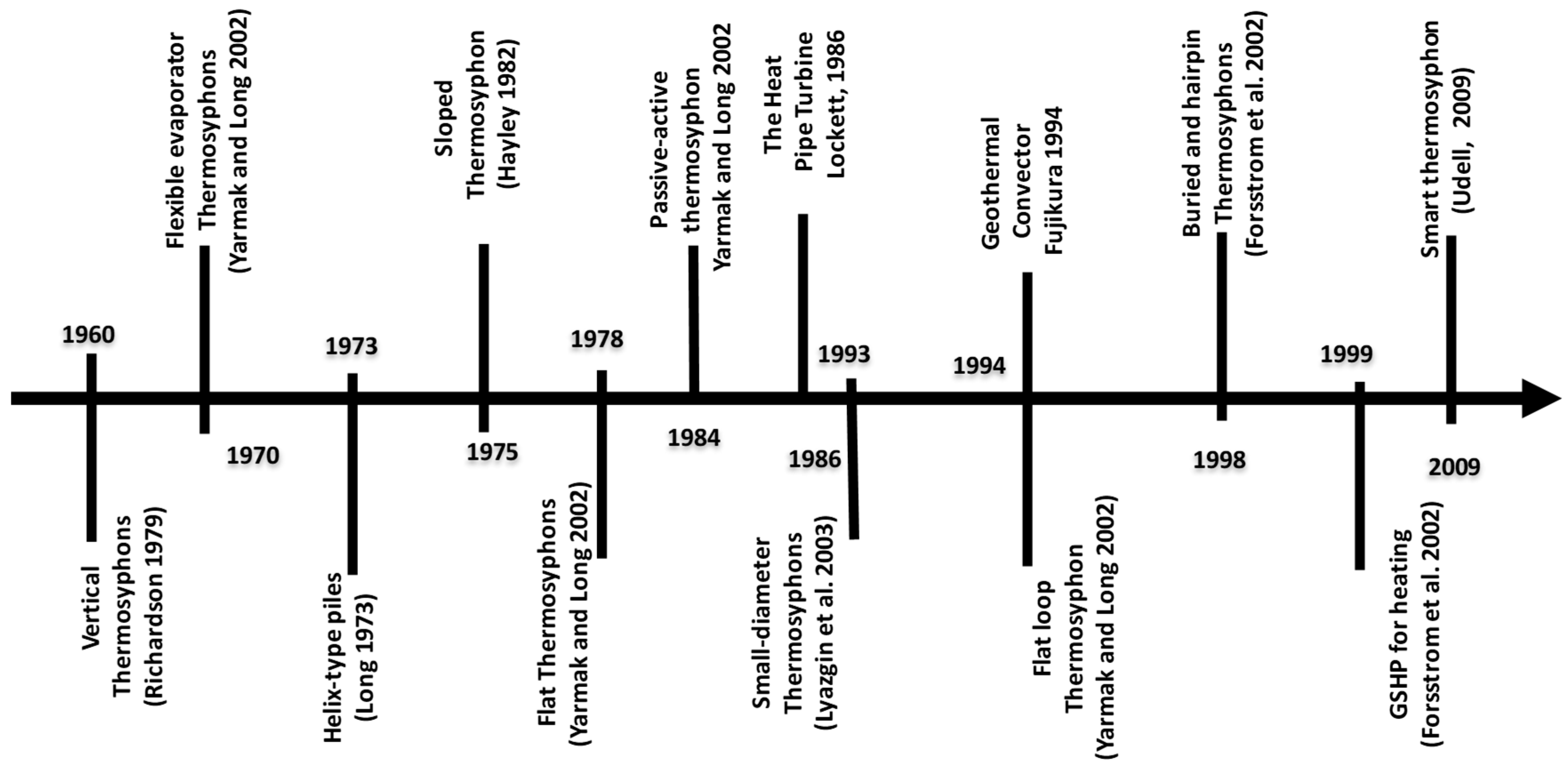
1.2. Main Stages of GCT Development
1.3. Latest Developments
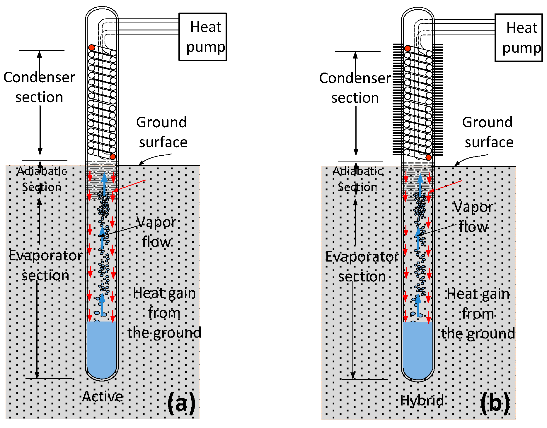
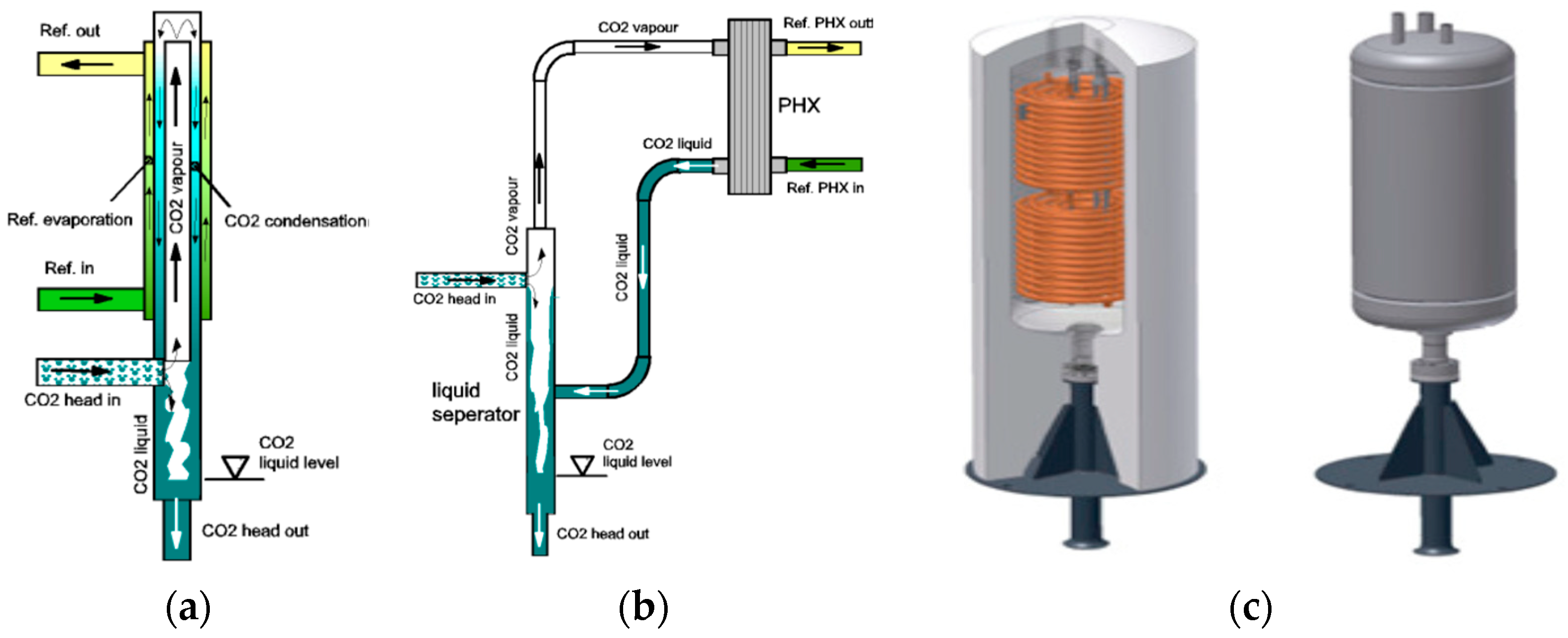
1.3.1. GCT-Assisted Heat Pump (GCT-HP)
1.3.2. Smart or Reversible GCT
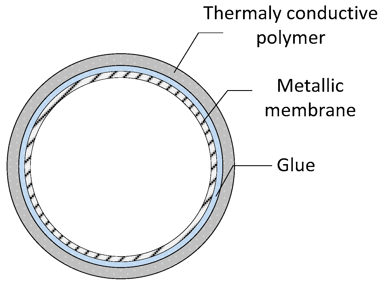
1.3.3. Polymer Thermosiphons
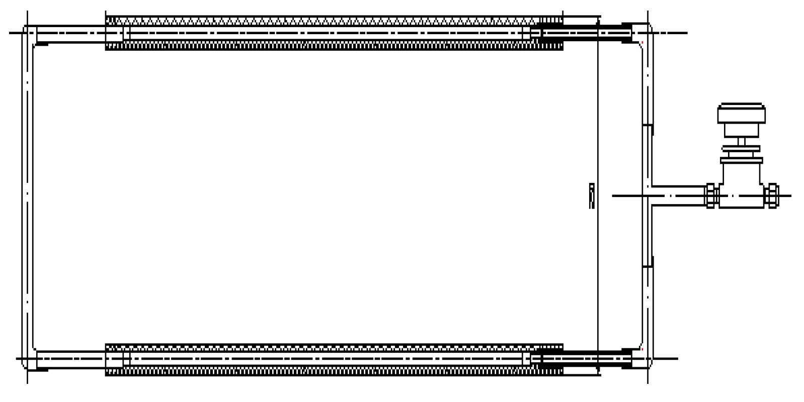
1.3.4. VapordynamicThermosiphons
1.3.5. Thermosiphon with Internal Screw Insert
1.3.6. Thermosiphon Heat Transfer Device with Bubble Driven Rotor
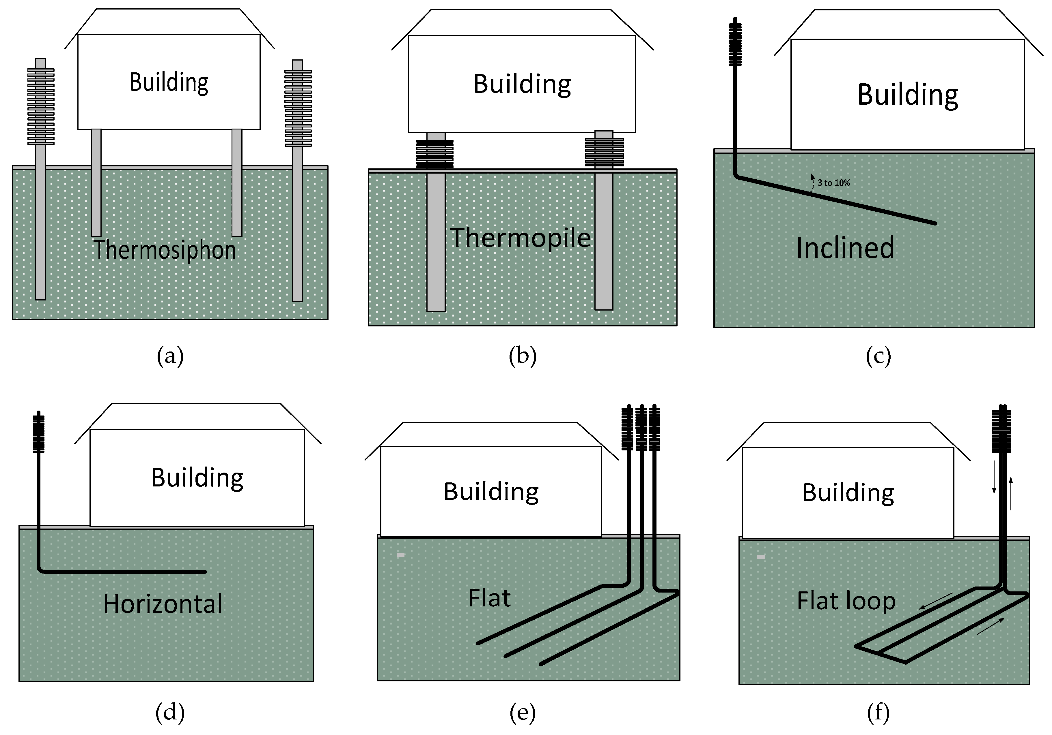
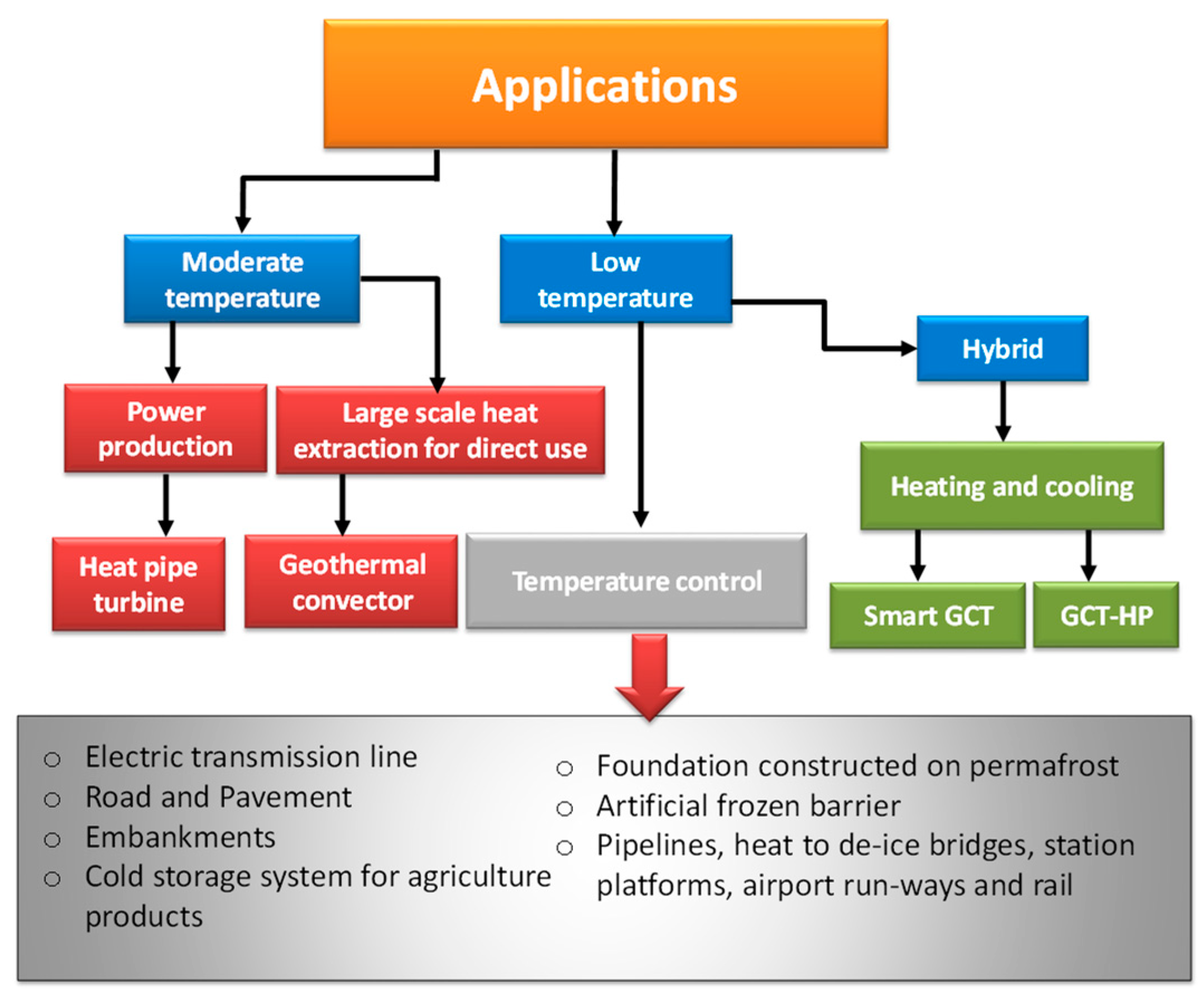
2. Thermosiphon Applications
3. Performance of GCTs
- Climatic conditions: ambient temperature, solar radiation, wind effect, rain, humidity, sky temperature, coolant flow rate and temperature, site constraints such as orientation, tilt, and surroundings;
- Thermosiphon characteristics: material properties, surface coatings, absorptance, geometry such as diameter and length of various sections (evaporator section, adiabatic, and condenser sections), working fluid properties, filling ratio, and internal working pressure;
- Ground thermal properties: temperature, thermal conductivity, and thermal diffusivity;
- Other conditions: load characteristics related to the application and climate warming.
3.1. Mathematical Modeling, Simulations, and Parametric Studies
3.1.1. Modeling and Simulation
3.1.2. Parametric Studies
3.2. Experimental Studies on GCTs
- Provide a better understanding of the heat transfer processes occurring in the different GCT types, analyze the cooling and heating mechanisms of the different engineering measures proposed, and evaluate their performance and the main controlling factors;
- Provide laboratory or field data for the validation of numerical simulation models, and the analysis and improvement of long-term performance predictions;
- Further optimize the design, functioning, monitoring, and key design parameters in different environmental settings (e.g., in permafrost regions), and identify the aspects and the methods to be improved;
- Develop new engineering measures for integrating GCTs into the construction to produce a satisfactory performance, technical feasibility, and cost-effectiveness.
3.2.1. Performance Evaluation
3.2.2. Working Fluid
3.2.3. Pipe Material
3.2.4. Condenser and Evaporator Design
3.2.5. Experimental Data
3.2.6. Optimized Design, Operation, and Monitoring
3.2.7. Remarkable Engineering Features of Thermosiphons
4. Conclusion
- The inclusion of GCT technology has been successfully demonstrated in different studies for a variety of applications. Further cases continue to be under study either because they are still at the concept stage (large scale extraction of geothermal energy and power production using GCTs) or they are part of newly undertaken research (e. g, smart thermosiphons);
- A variety of analytical and numerical models have been used to evaluate and improve the performance of GCTs. The objectives and the requirements of each development case vary from one application to another. As performance indicators of each application are different and depend significantly on specific location and application characteristics, it was difficult to compare different cases;
- The development of the GCT-HP concept appears to be very interesting not only for single-family house uses, but also for meeting the needs of high capacity urban heating systems. However, their use remains limited compared to conventional ground source heat pumps;
- Given increased concern over the impacts of global warming, the “hybrid GCT” approach may represent the best approach for designing important infrastructures in permafrost. This approach moves from passive to proactive permafrost cooling, in order to better deal with the potential consequences of global warming.
Funding
Conflicts of Interest
Abbreviations
| A | area (m2) |
| C | conductance (m/°C) |
| cp | specific heat J/(kg·°C) |
| d | diameter (m) |
| g | acceleration of gravity (m/s2) |
| R | thermal resistance (°C/m) |
| H | enthalpy per unit mass |
| h | convection heat transfer coefficient (W/m2·°C) |
| k | thermal conductivity W/(m·°C) |
| L | length of section |
| mass flow rate (kg/s) | |
| P | pressure (Pa) |
| Q | heat flow (W) |
| q | heat flux (W/m2) |
| r | radius (m) |
| T | temperature (°C) |
| t | time (s) |
| x | vapor quality (dimensionless) |
| COP | coefficient of performance |
| CL-GCT | closed loop, ground coupled thermosiphon |
| GCT-HP | GCT-assisted Heat Pump |
| GCHP | ground coupled heat pumps |
| GCT | ground coupled thermosiphons |
| GC | geothermal convector |
| HPT | heat pipe turbine |
| PA | polyamide |
| PCTFE | polychlorotrifluoroethylene |
| PP | polypropylene |
| PTFE | polytetrafluoroethylene |
| PVDF | polyvinylidene fluoride |
| ST-GCT | single tube, ground coupled thermosiphon thermosiphon |
| TMD | thermo-stabilizer with Improved Productivity |
| TRC | thermosiphon rankine cycle |
| TPCT | two-phase closed thermosiphon |
| VDT | vapordynamic thermosiphon |
| α | thermal diffusivity (m2/s) |
| Δ | gradient |
| η | heat exchange efficiency |
| µ | dynamic viscosity (Pa.s) |
| φ | diameter (m) |
| ρ | density (kg/m3) |
| atm | atmospheric |
| c | condenser section |
| conv | convection |
| e | evaporator section |
| eff | effective |
| f | fluid |
| i | inner pipe wall |
| l | liquid film |
| m | mean |
| o | outer pipe wall |
| s | soil/solid/freezing |
| sat | saturation |
| T | total |
| v | vapor |
| w | water |
References
- Julia, R. Thermosiphon Loops for Heat Extraction from the Ground. Master’s Thesis, KTH School of Industrial Engineering and Management, Stockholm, Sweden, 2008. [Google Scholar]
- Kaltschmitt, M.; Streicher, W.; Wiese, A. Renewable Energy Technology Economics and Environment; Springer Science & Business Media: Berlin/Heidelberg, Germany, 2007; p. 564. ISBN 978-3-540-70949-7. [Google Scholar]
- Franco, A.; Vaccaro, M. On the use of heat pipe principle for the exploitation of medium low temperature geothermal resources. Appl. Therm. Eng. 2013, 59, 189–199. [Google Scholar] [CrossRef]
- Aresti, L.; Christodoulides, P.; Florides, G. A review of the design aspects of ground heat exchangers. Renew. Sustain. Energy Rev. 2018, 92, 757–773. [Google Scholar] [CrossRef]
- Florides, G.; Kalogirou, S. Ground heat exchangers—A review of systems, models and applications. Renew. Energy 2007, 32, 2461–2478. [Google Scholar] [CrossRef]
- Richardson, P. Tough Alaska conditions prove new pile design’s versatility. Alaska Constr. Oil 1979, 20–28. [Google Scholar]
- Wu, J.; Ma, W.; Sun, Z.; Wen, Z. In-situ study on cooling effect of the two-phase closed thermosyphon and insulation combinational embankment of the Qinghai-Tibet Railway. Cold Reg. Sci. Technol. 2010, 60, 234–244. [Google Scholar] [CrossRef]
- Wagner, A. Review of Thermosyphon Applications. The US Army Engineer Research and Development Center: Hanover, NH, USA ERDC/CRREL-TR-14-1. , 2014. Available online: http://acwc.sdp.sirsi.net/client/default (accessed on 21 September 2018).
- Long, E.L.; Zarling, J.P. Passive Techniques for Ground Temperature Control. In Thermal Analysis, Construction, and Monitoring Methods for Frozen Ground; American Society of Civil Engineers: Reston, VA, USA, 2004; pp. 77–165. [Google Scholar]
- Mc Fadden, T. Design Manual for Stabilizing Foundations on Permafrost 2001, 181. Available online: https://www.uaf.edu/ces/energy/housing_energy/resources/Permafrost-design-manual.pdf (accessed on 21 September 2018).
- Yarmak, E.; Long, E. Recent Developments in Thermosyphon Technology. In Proceedings of the 11th International Conference on Cold Regions Engineering, Anchorage, AK, USA, 20–22 May 2002; pp. 656–662. [Google Scholar]
- McFadden, T.T.; Bennett, F.L. Construction in Cold Regions: A Guide for Planners, Engineers, Contractors, and Managers; John Wiley & Sons: Hoboken, NJ, USA, 1991; ISBN-13: 978-0471525035. [Google Scholar]
- Carotenuto, A.; Casarosa, C.; Martorano, L. The geothermal convector: Experimental and numerical results. Appl. Therm. Eng. 1999, 19, 349–374. [Google Scholar] [CrossRef]
- Bertsch, S.; Groll, E.A.; Whitacre, K. Modeling of a CO2 thermosyphon for a ground source heat pump application. In Proceedings of the 8th International Energy Agency for Heat Pump Conference, Las Vegas, NY, USA, 30 May–2 June 2005. [Google Scholar]
- Wagner, A.M.; Edward, Y., Jr. Using Frozen Barriers for Containment of Contaminants. Cold Regions Research and Engineering Laboratory, US Army Engineer Research and Development Center Hanover United States, 2017. Available online: https://apps.dtic.mil/docs/citations/AD1039597 (accessed on 21 September 2018).
- National Standard of Canada. Thermosyphon Foundations for Buildings in Permafrost Regions; National Standard of Canada: Ottawa, ON, Canada, 2014; ISBN 9781771396042. [Google Scholar]
- Wagner, A.M.; Yarmak, E. Demonstration of an Artificial Frozen Barrier Cold Regions Research Demonstration of an Artificial Frozen Barrier. 2012. Available online: https://apps.dtic.mil/docs/citations/ADA571582 (accessed on 21 January 2019).
- Gaugler, R.S. Heat Transfer Device. U.S. Patent US2,350,348A, 21 December 1942. [Google Scholar]
- Reay, D.; McGlen, R.; Kew, P. Heat Pipes Theory and Design, 5th ed.; Butterworth Heinemann: Oxford, UK, 2006; ISBN 9780750667548. [Google Scholar]
- Heuer, C.E. The Application of Heat Pipes on the Trans-Alaska Pipeline. (No. CRREL-SR-79-26). Cold Regions Research and Engineering Lab Hanover NH, 1979; p. 34. Available online: http://dtic.mil/dtic/tr/fulltext/u2/a073597.pdf (accessed on 21 September 2018).
- Nguyen, T.; Johnson, P.; Akbarzadeh, A.; Gibson, K.; Mochizuki, M. Design, manufacture and testing of a closed cycle thermosyphonrankine engine. Heat Recov. Syst. CHP 1995, 15, 333–346. [Google Scholar] [CrossRef]
- Ziapour, B.M. Performance analysis of an enhanced thermosyphon Rankine cycle using impulse turbine. Energy 2009, 34, 1636–1641. [Google Scholar] [CrossRef]
- Lockett, G. Single borehole geothermal energy extraction system for electrical power generation. In Proceedings of the Eleventh Workshop on Geothermal Reservoir Engineering, Stanford, CA, USA, 21–23 January 1986; pp. 215–216. [Google Scholar]
- Holubec, I. Flat Loop Thermosyphon Foundations in Warm Permafrost. Government of Northwest Territories Thermosyphon Foundations in Warm Permafrost—Report; 2008; p. 119. Available online: https://pievc.ca/government-northwest-territories-thermosyphon-foundations-warm-permafrost (accessed on 21 September 2018).
- Kruse, H. Terrestrial Heat Probe for Use in Heat Pump System for Heating. German Patent DE19860328A1, 24 December 1998. [Google Scholar]
- Kruse, H.; Russmann, H. The Status of Development and Research on CO2 Earth Heat Pipes for Geothermal Heat Pumps. International High Performance Buildings Conference. Paper 51. Available online: http://docs.lib.purdue.edu/ihpbc/51 (accessed on 21 September 2018).
- Ochsner, K. Carbon dioxide heat pipe in conjunction with a ground source heat pump (GSHP). Appl. Therm. Eng. 2008, 28, 2077–2082. [Google Scholar] [CrossRef]
- Kruse, H.; Russmann, H. Novel CO2-heat pipe as earth probe for heat pumps without auxiliary pumping energy. In Proceedings of the 8th International IEA Heat Pump Conference, Las Vegas, NV, USA, 30 May–2 June 2005. [Google Scholar]
- Rieberer, R. Naturally circulating probes and collectors for ground-coupled heat pumps. Int. J. Refrig. 2005, 28, 1308–1315. [Google Scholar] [CrossRef]
- Acuña, J.; Palm, B.; Khodabandeh, R.; Weber, K.; Ab, E. Distributed Temperature Measurements on a U-Pipe Thermosyphon Borehole Heat Exchanger with CO2. In Proceedings of the 9th IIR Gustav Lorentzen Conference, Sydney, Australia, 12–14 April 2010. [Google Scholar]
- Ebeling, J.C.; Kabelac, S.; Luckmann, S.; Kruse, H. Simulation and experimental validation of a 400 m vertical CO2 heat pipe for geothermal application. Heat Mass Transf. 2017, 53, 3257–3265. [Google Scholar] [CrossRef]
- Ebeling, J.C.; Luo, X.; Kabelac, S.; Luckmann, S.; Kruse, H. Dynamic simulation and experimental validation of a two-phase closed thermosyphon for geothermal application. Propuls. Power Res. 2017, 6, 107–116. [Google Scholar] [CrossRef]
- Haynes, F.D.; Zarling, P.; Quinn, F.; Sollecito, P.E.M. Passive-Active Thermosyphon. U.S. Patent US07,883,443, 15 May 1992. [Google Scholar]
- Udell, K.S.; Jankovich, P.; Kekelia, B. Seasonal underground thermal energy storage using smart thermosiphon technology. In Proceedings of the Geothermal Resources Council 2009, Annual Meeting, GRC Transactions, Reno, NV, USA, 4–7 October 2009; Volume 33, pp. 643–647. [Google Scholar]
- Kekelia, B.; Udell, K.S. Grid-Independent Air Conditioning Using Underground Thermal Energy Storage (UTES) and Reversible Thermosiphon Technology: Experimental Results. In Proceedings of the ASME 2011 5th International Conference on Energy Sustainability, Washington, DC, USA, 7–10 August 2011; pp. 1245–1254. [Google Scholar]
- Jankovich, P.M. Seasonal Underground Thermal Energy Storage Using Smart Thermosiphon Arrays. Ph.D. Thesis, The University of Utah, Salt Lake City, UT, USA, 2012. [Google Scholar]
- Rieberer, R.; Moser, H. Naturally Circulating Collector for Heat Pumps-Initial Results. In Proceedings of the 7th IIR Gustav Lorentzen Conference on Natural Working Fluids, Trondheim, Norway, 28–31 May 2006. [Google Scholar]
- Vasiliev, L.L.; Academy, N.; Vassiliev, L.L.; Academy, N.; Vassiliev, L.L. Heat Pipes and nanotechnologies. In Microscale and Nanoscale Heat Transfer: Analysis, Design, and Application Edition; CRC Press: Boca Raton, FL, USA, 2016; Chapter 8; p. 505. ISBN 9781498736312. [Google Scholar]
- Vasiliev, L.; Grakovich, L.P.; Rabetsky, M.; Vasiliev, L.J. Heat transfer enhancement in heat pipes and thermosyphons using nanotechnologies (nanofluids, nanocoatings, and nanocomposites) as an hp envelope. Heat Pipe Sci. Technol. Int. J. 2013, 4, 251–275. [Google Scholar] [CrossRef]
- Wang, X.; Fan, H.; Zhu, Y.; Zhu, M. Heat Transfer Simulation and Analysis of Ice and Snow Melting System Using Geothermy by Super-long Flexible Heat Pipes. Energy Procedia 2017, 105, 4724–4730. [Google Scholar] [CrossRef]
- Zhuravlyov, A.S.; Vasiliev, L.L.; Vasiliev, L.L., Jr. Horizontal vapordynamicthermosyphons, fundamentals and practical applications. Heat Pipe Sci. Technol. Int. J. 2013, 4, 39–52. [Google Scholar] [CrossRef]
- Vasiliev, L.L.; Kiselev, V.G.; Valery, A.; Rudnev, E.A.; Nesvit, V.A.; Dunaevsky, L.M.; Tverdokhleb, N.F.; Bogdanov, V.M.; Davis, P.E.W. Heat-Transfer Device. U.S. Patent 45,554,966, 26 November 1985. [Google Scholar]
- Vasiliev, L.; Vasiliev, L.; Zhuravlyov, A.; Shapovalov, A.; Rodin, A. Vapordynamicthermosyphon - Heat transfer two-phase device for wide applications. Arch. Thermodyn. 2015, 36, 65–76. [Google Scholar] [CrossRef]
- Vasiliev, L.L.; Grakovich, L.P.; Rabetsky, M.I.; Vassiliev, L.L.; Zhuravlyov, A.S. Thermosyphons with innovative technologies. Appl. Therm. Eng. 2017, 111, 1647–1654. [Google Scholar] [CrossRef]
- Vasiliev, L.L.; Vaaz, S.L. Freezing and Heating of Ground by Means of Cooling Devices; NaukaiTekhnika: Minsk, Belarus, 1986. (In Russian) [Google Scholar]
- Read, J.P.R.H.; Pullen, K.R.; Gordon, M. A Thermosyphon Heat Transfer Device with Bubble Driven Rotor. WO2011158008A3, 18 June 2010. [Google Scholar]
- Long, E.L. Designing friction piles for increased stability at lower installed cost in permafrost. In Proceedings of the Permafrost-The North American Contribution to the Second International Conference, Yakutsk; National Academy of Sciences: Washington, DC, USA, 1973. [Google Scholar]
- Yarmak, E. Permafrost Foundations Thermally Stabilized Using Thermosyphons. In Proceedings of the OTC Arctic Technology Conference, Copenhagen, Denmark, 23–25 March 2015; pp. 23–25. [Google Scholar]
- Acuña, J. Distributed Thermal Response Tests: New insights on U-Pipe and Coaxial Heat Exchangers in Groundwater-Filled Boreholes. Ph.D. Dissertation, KTH Royal Institute of Technology, Stockholm, Sweden, 2013. [Google Scholar]
- Mashiko, K.; Mochizuki, M.; Watanabe, Y.; Kanai, Y.; Eguchi, K.; Shiraishi, M. Development of a Large Scale Loop Type Gravity Assisted Heat Pipe Having Showering Nozzles. In Proceedings of the 4th International Heat Pipe Symposium, Tsukuba, Japan, 16–18 May 1994; pp. 264–274. [Google Scholar]
- Hayley, D.W. Application of heat pipes to design of shallow foundations on permafrost. In Proceedings of the 4th Canadian Permafrost Conference; National Research Council of Canada: Ottawa, ON, Canada, 1982; pp. 535–544. [Google Scholar]
- Wang, X.; Zhu, Y.; Zhu, M.; Zhu, Y.; Fan, H.; Wang, Y. Thermal analysis and optimization of an ice and snow melting system using geothermy by super-long flexible heat pipes. Appl. Therm. Eng. 2017, 112, 1353–1363. [Google Scholar] [CrossRef]
- Wang, X.; Wang, Y.; Wang, Z.; Liu, Y.; Zhu, Y.; Chen, H. Simulation-based analysis of a ground source heat pump system using super-long flexible heat pipes coupled borehole heat exchanger during heating season. Energy Convers. Manag. 2018, 164, 132–143. [Google Scholar] [CrossRef]
- Xu, J.; Goering, D.J. Experimental validation of passive permafrost cooling systems. Cold Reg. Sci. Technol. 2008, 53, 283–297. [Google Scholar] [CrossRef]
- Zhi, W.; Yu, S.; Wei, M.; Jilin, Q.; Wu, J. Analysis on effect of permafrost protection by two-phase closed thermosyphon and insulation jointly in permafrost regions. Cold Reg. Sci. Technol. 2005, 43, 150–163. [Google Scholar] [CrossRef]
- Chan, C.W.; Siqueiros, E.; Ling-Chin, J.; Royapoor, M.; Roskilly, A.P. Heat utilisation technologies: A critical review of heat pipes. Renew. Sustain. Energy Rev. 2015, 50, 615–627. [Google Scholar] [CrossRef]
- Vasiliev, L.L.; Vasiliev, L.L., Jr. Horizontal vapordynamic thermosyphons, fundamentals and practical applications. In Proceedings of the 16th International Heat Pipe Conference, Lyon, France, 20–24 May 2012. [Google Scholar]
- Grakovich, M.I.; Rabetsky, L.L.; Vasiliev, L.L.V.J. Polymer flat loop thermosyphons. Heat Pipe Sci. Technol. Int. J. 2014, 5, 1–4. [Google Scholar] [CrossRef]
- Nydahl, J.E.; Pell, K.; Lee, R. Bridge deck heating with ground-coupled heat pipes: Analysis and design. ASHRAE Trans. 1987, 93, 939–958. [Google Scholar]
- Zorn, R.; Steger, H.; Kölbel, T. De-Icing and Snow Melting System with Innovative Heat Pipe Technology. In Proceedings of the World Geothermal Congress, Melbourne, Australia, 19–25 April 2015; pp. 1–6. [Google Scholar]
- Vasiliev, L.L. Heat pipes for ground heating and cooling. Heat Recov. Syst. CHP 1988, 8, 125–139. [Google Scholar] [CrossRef]
- Griffin, R.G. Highway Bridge Deicing Using Passive Heat Sources. Colorado Department of Highways, 1982; p. 71. Available online: https://www.codot.gov/programs/research/pdfs/archive/passivedeicing.pdf (accessed on 21 September 2018).
- Fukuda, M.; Tsuchiya, F.; Ryokai, K.; Mochizuki, M.; Mashiko, K. Development of an artificial permafrost storage using heat pipes. In Proceedings of the 7th International Heat Pipe Conference, Moscow, Russia, 21–25 May 1990; 1990; Volume 2, pp. 305–317. [Google Scholar]
- Dussadee, N.; Kiatsiriroat, T. Performance analysis and economic evaluation of thermosyphon paddy bulk storage. Appl. Therm. Eng. 2004, 24, 401–414. [Google Scholar] [CrossRef]
- Zorn, R.; Steger, H.; Kölbel, T.; Kruse, H. Deep Borehole Heat Exchanger with a CO2 Gravitational Heat Pipe. In Proceedings of the GeoCongress 2008: Geosustainability and Geohazard Mitigation, New Orleans, LA, USA, 9–12 March 2008; pp. 899–906. [Google Scholar]
- Rieberer, R.; Mittermayr, K.; Halozan, H. CO2 Thermosyphons as Heat Source System for Heat Pumps-4 Years of Market Experience. In Proceedings of the 8th IEA Heat Pump Conference, Las Vegas, NV, USA, 30 May–2 June 2005. [Google Scholar]
- Udell, K.S.; Kekelia, B.; Jankovich, P. Net Zero Energy Air Conditioning Using Smart Thermosiphon Arrays. ASHRAE Trans. 2011, 117, 892–898. [Google Scholar]
- Kekelia, B. Heat Transfer to and from a Reversible Thermosiphon Placed in Porous Media. Ph.D. Thesis, The University of Utah, Salt Lake City, UT, USA, 2012. Available online: https://search.proquest.com/openview/d6b0c7ce0d1b891aa8a14e5d07d0e6a3/1?cbl=18750&diss=y&pq-origsite=gscholar (accessed on 21 September 2018).
- Mu, Y.; Li, G.; Yu, Q.; Ma, W.; Wang, D.; Wang, F. Numerical study of long-term cooling effects of thermosyphons around tower footings in permafrost regions along the Qinghai-Tibet Power Transmission Line. Cold Reg. Sci. Technol. 2016, 121, 237–249. [Google Scholar] [CrossRef]
- Wei, M.; Guodong, C.; Qingbai, W. Construction on permafrost foundations: Lessons learned from the Qinghai-Tibet railroad. Cold Reg. Sci. Technol. 2009, 59, 3–11. [Google Scholar] [CrossRef]
- Jin, H.; Hao, J.; Chang, X.; Zhang, J.; Yu, Q.; Qi, J.; Lü, L.; Wang, S. Zonation and assessment of frozen-ground conditions for engineering geology along the China–Russia crude oil pipeline route from Mo’he to Daqing, Northeastern China. Cold Reg. Sci. Technol. 2010, 64, 213–225. [Google Scholar] [CrossRef]
- Li, G.; Yu, Q.; Ma, W.; Chen, Z.; Mu, Y.; Guo, L.; Wang, F. Freeze–thaw properties and long-term thermal stability of the unprotected tower foundation soils in permafrost regions along the Qinghai–Tibet Power Transmission Line. Cold Reg. Sci. Technol. 2016, 121, 258–274. [Google Scholar] [CrossRef]
- Wang, H.; Zhao, J.; Chen, Z. Experimental investigation of ice and snow melting process on pavement utilizing geothermal tail water. Energy Convers. Manag. 2008, 49, 1538–1546. [Google Scholar] [CrossRef]
- Wagner, A.M. Creation of an artificial frozen barrier using hybrid thermosyphons. Cold Reg. Sci. Technol. 2013, 96, 108–116. [Google Scholar] [CrossRef]
- Lynn, S.W.; Rhodes, C. Evaluation of a vertical frozen soil barrier at oak ridge national laboratory. Remediat. J. 2000, 10, 15–33. [Google Scholar] [CrossRef]
- Eskilson, P. Thermal Analysis of Heat Extraction Boreholes. Ph.D. Thesis, Lund University, Department of Mathematical Physics, Lund, Sweden, 1987. [Google Scholar]
- Li, M.; Lai, A.C.K. Review of analytical models for heat transfer by vertical ground heat exchangers (GHEs): A perspective of time and space scales. Appl. Energy 2015, 151, 178–191. [Google Scholar] [CrossRef]
- Rees, S. Advances in Ground-Source Heat Pump Systems, 1st ed.; Woodhead Publishing: Sawston, UK, 2016; p. 482. ISBN 0081003226. [Google Scholar]
- Yang, H.; Cui, P.; Fang, Z. Vertical-borehole ground-coupled heat pumps: A review of models and systems. Appl. Energy 2010, 87, 16–27. [Google Scholar] [CrossRef]
- Carslaw, H.S.; Jaeger, J.C. Conduction of Heat in Solids, 2nd ed.; Clarendon Press: Oxford, UK, 1959. [Google Scholar]
- Ingersoll, L.R.; Zabel, O.J.; Ingersoll, A.C. Heat Conduction with Engineering, Geological, and Other Applications, 3rd ed.; Thames and Hudson: London, UK, 1955; p. 325. [Google Scholar] [CrossRef]
- Zeng, H.Y.; Diao, N.R.; Fang, Z.H. A finite line-source model for boreholes in geothermal heat exchangers. Heat Transf. Asian Res. 2002, 31, 558–567. [Google Scholar] [CrossRef]
- Zeng, H.; Diao, N.; Fang, Z. Heat transfer analysis of boreholes in vertical ground heat exchangers. Int. J. Heat Mass Transf. 2003, 46, 4467–4481. [Google Scholar] [CrossRef]
- Yavuzturk, C.; Spitler, J.D.; Rees, S.J. A Transient two-dimensional finite volume model for the simulation of vertical U-tube ground heat exchangers. ASHRAE Trans. 1999, 105, 465–474. [Google Scholar]
- Bozzoli, F.; Pagliarini, G.; Rainieri, S.; Schiavi, L. Estimation of soil and grout thermal properties through a TSPEP (two-step parameter estimation procedure) applied to TRT (thermal response test) data. Energy 2011, 36, 839–846. [Google Scholar] [CrossRef]
- Al-Khoury, R. Computational Modeling of Shallow Geothermal Systems; CRC Press: Boca Raton, FL, USA; London, UK, 2012; ISBN 0415596270. [Google Scholar]
- Beier, R.A.; Smith, M.D.; Spitler, J.D. Reference data sets for vertical borehole ground heat exchanger models and thermal response test analysis. Geothermics 2011, 40, 79–85. [Google Scholar] [CrossRef]
- Salim Shirazi, A.; Bernier, M. A small-scale experimental apparatus to study heat transfer in the vicinity of geothermal boreholes. HVAC&R Res. 2014, 20, 819–827. [Google Scholar]
- Chen, L.; Yu, W.; Lu, Y.; Liu, W. Numerical simulation on the performance of thermosyphon adopted to mitigate thaw settlement of embankment in sandy permafrost zone. Appl. Therm. Eng. 2018, 128, 1624–1633. [Google Scholar] [CrossRef]
- Paramonov, V.N.; Sakharov, I.I. Calculations of thermal stabilization of transport embankments and their bases. Procedia Eng. 2017, 189, 472–477. [Google Scholar] [CrossRef]
- Zhao, X.Y.; Wang, J.; Wang, Y.Z. The temperature control technology of bridge foundation in permafrost regions. Procedia Eng. 2017, 210, 235–239. [Google Scholar]
- Pei, W.; Zhang, M.; Li, S.; Lai, Y.; Jin, L.; Zhai, W.; Yu, F.; Lu, J. Geotemperature control performance of two-phase closed thermosyphons in the shady and sunny slopes of an embankment in a permafrost region. Appl. Therm. Eng. 2017, 112, 986–998. [Google Scholar] [CrossRef]
- Lim, H.; Kim, C.; Cho, Y.; Kim, M. Energy saving potentials from the application of heat pipes on geothermal heat pump system. Appl. Therm. Eng. 2017, 126, 1191–1198. [Google Scholar] [CrossRef]
- Yu, F.; Zhang, M.; Lai, Y.; Liu, Y.; Qi, J.; Yao, X. Crack formation of a highway embankment installed with two-phase closed thermosyphons in permafrost regions: Field experiment and geothermal modelling. Appl. Therm. Eng. 2017, 115, 670–681. [Google Scholar] [CrossRef]
- Zhang, M.; Pei, W.; Lai, Y.; Niu, F.; Li, S. Numerical study of the thermal characteristics of a shallow tunnel section with a two-phase closed thermosyphon group in a permafrost region under climate warming. Int. J. Heat Mass Transf. 2017, 104, 952–963. [Google Scholar] [CrossRef]
- Lu, Y.; Yi, X.; Yu, W.; Liu, W. Numerical analysis on the thermal regimes of thermosyphon embankment in snowy permafrost area. Sci. Cold Arid Reg. 2017, 9, 580–586. [Google Scholar] [CrossRef]
- Ozsoy, A.; Yildirim, R. Prevention of icing with ground source heat pipe: A theoretical analysis for Turkey’s climatic conditions. Cold Reg. Sci. Technol. 2016, 125, 65–71. [Google Scholar] [CrossRef]
- Mu, Y.; Wang, G.; Yu, Q.; Li, G.; Ma, W.; Zhao, S. Thermal performance of a combined cooling method of thermosyphons and insulation boards for tower foundation soils along the Qinghai–Tibet Power Transmission Line. Cold Reg. Sci. Technol. 2016, 121, 226–236. [Google Scholar] [CrossRef]
- Hartmann, F.; Behrend, R.; Hantsch, A.; Grab, T.; Gross, U. Numerical investigation of the performance of a partially wetted geothermal thermosyphon at various power demand schemes. Geothermics 2015, 55, 99–107. [Google Scholar] [CrossRef]
- Grab, D.I.T.; Storch, D.I.T.; Wagner, S.; Gross, U. Wechselwirkungen zwischen Heiz-und Kühlkreislauf bei einem geothermischen Direktverdampfer-Sondenfeld. Deutsche Kälte-und Klimatagung, DKV, Magdeburg. 2010. Available online: https://tu-freiberg.de/sites/default/files/media/professur-fuer-technische-thermodynamik-15264/Publikationen_Grab/2010-grab-dkv-magdeburg-wechselwirkungen-zw.-heiz-und-kuehlkreislauf.pdf (accessed on 20 February 2019).
- Abdalla, B.; Fan, C.; McKinnon, C.; Gaffard, V. Numerical Study of Thermosyphon Protection for Frost Heave. In Proceedings of the ASME 2015 34th International Conference on Ocean, Offshore and Arctic Engineering, St. John’s, NL, Canada, 31 May–5 June 2015. [Google Scholar]
- Mu, Y.; Li, G.; Yu, Q.; Ma, W.; Zhang, Q.; Guo, L.; Chen, Z. Numerical simulation of heat transfer processes of cone-cylinder pile and cooling effects of thermosyphon along the Qinghai–Tibet DC Interconnection project. J. Glaciol. Geocryol. 2014, 36, 106–117. [Google Scholar]
- Ma, C.; Wu, X.; Gao, S. Analysis and applications of a two-phase closed thermosyphon for improving the fluid temperature distribution in wellbores. Appl. Therm. Eng. 2013, 55, 1–6. [Google Scholar] [CrossRef]
- Filippeschi, S.; Su, Y.; Riffat, S.B.; Lucio, L. Feasibility of periodic thermosyphons for environmentally friendly ground source cooling applications. Int. J. Low-Carbon Technol. 2013, 8, 117–123. [Google Scholar] [CrossRef]
- Hantsch, A.; Gross, U. Numerical investigation of partially-wetted geothermal heat pipe performance. Geothermics 2013, 47, 97–103. [Google Scholar] [CrossRef]
- Nakaoka, J. Heat Transfer Analysis of Thermosiphons and U-Tube Ground Source Heat Pumps. Masters’s Thesis, The University of Utah, Salt Lake City, UT, USA, 2012. [Google Scholar]
- Dong, Y.; Lai, Y.; Chen, W. Cooling effect of combined L-shaped thermosyphon, crushed-rock revetment and insulation for high-grade highways in permafrost regions. Chin. J. Geotechn. Eng. 2012, 34, 1043–1049. [Google Scholar]
- Zhang, M.; Lai, Y.; Zhang, J.; Sun, Z. Numerical study on cooling characteristics of two-phase closed thermosyphon embankment in permafrost regions. Cold Reg. Sci. Technol. 2011, 65, 203–210. [Google Scholar] [CrossRef]
- Wang, Z.; Mcclure, M.W.; Horne, R.N. A single-well EGS configuration using a thermosyphon. In Proceedings of the 34th Workshop on Geothermal Reservoir Engineering, Stanford, CA, USA, 9–11 February 2009. Paper SGP-TR-187. [Google Scholar]
- Jardine, J.D.; Long, E.L.; Yarmak, E. Thermal analysis of forced-air and thermosyphon cooling systems for the Inuvik airport expansion: Discussion. Can. Geotech. J. 1992, 29, 998–1001. [Google Scholar] [CrossRef]
- Smith, L.B.; Graham, J.P.; Nixon, J.F.; Washuta, A.S. Thermal analysis of forced-air and thermosyphon cooling systems for the Inuvik airport expansion. Can. Geotech. J. 1991, 28, 399–409. [Google Scholar] [CrossRef]
- Cui, P.; Yang, H.; Fang, Z. Numerical analysis and experimental validation of heat transfer in ground heat exchangers in alternative operation modes. Energy Build. 2008, 40, 1060–1066. [Google Scholar] [CrossRef]
- Yavuzturk, C.; Spitler, J.D. Field validation of a short time step model for vertical ground-loop heat exchangers/Discussion. ASHRAE Trans. 2001, 107, 617. [Google Scholar]
- Javed, S. New Analytical and Numerical Solutions for the Short-term Analysis of Vertical Ground Heat Exchangers. ASHRAE Trans. 2011, 117, 3–12. [Google Scholar]
- Li, M.; Lai, A.C.K. Analytical model for short-time responses of ground heat exchangers with U-shaped tubes: Model development and validation. Appl. Energy 2013, 104, 510–516. [Google Scholar] [CrossRef]
- Viskanta, R. Phase change heat transfer in porous media. In Proceedings of the 3rd International Symposium on Cold Region Heat Transfer, Fairbanks, AK, USA; 1991; pp. 1–24. [Google Scholar]
- Bazri, S.; Anjum, I.; Sajad, M. A review of numerical studies on solar collectors integrated with latent heat storage systems employing fi ns or nanoparticles. Renew. Energy 2018, 118, 761–778. [Google Scholar] [CrossRef]
- Yang, W.; Kong, L.; Chen, Y. Numerical evaluation on the effects of soil freezing on underground temperature variations of soil around ground heat exchangers. Appl. Therm. Eng. 2015, 75, 259–269. [Google Scholar] [CrossRef]
- Eslami-nejad, P.; Bernier, M. Freezing of geothermal borehole surroundings: A numerical and experimental assessment with applications. Appl. Energy 2012, 98, 333–345. [Google Scholar] [CrossRef]
- Sheshukov, A.Y.; Egorov, A.G. Frozen barrier evolution in saturated porous media. Adv. Water Resour. 2002, 25, 591–599. [Google Scholar] [CrossRef]
- Zhang, G.G.; Horne, W.B.T. Applications of numerical thermal analysis in engineering designs and evaluations for northern mines. In Proceedings of the 63rd Canadian Geotechnical Conference & 6th Canadian Permafrost Conference, Calgary, AB, Canada, 12–16 September 2010; pp. 617–624. [Google Scholar]
- Yu, F.; Qi, J.; Zhang, M.; Lai, Y.; Yao, X.; Liu, Y.; Wu, G. Cooling performance of two-phase closed thermosyphons installed at a highway embankment in permafrost regions. Appl. Therm. Eng. 2016, 98, 220–227. [Google Scholar] [CrossRef]
- Ho, I.-H.; Dickson, M. Numerical modeling of heat production using geothermal energy for a snow-melting system. Geomech. Energy Environ. 2017, 10, 42–51. [Google Scholar] [CrossRef]
- Duffie, J.A.; Beckman, W.A. Solar Engineering of Thermal Processes; John Wiley & Sons: Hoboken, NJ, USA, 2013; ISBN 0470873663. [Google Scholar]
- Givoni, B.; Mostrel, M. Passive solar journal. Passive Sol. J. 1982, 1, 229–238. [Google Scholar]
- Rao, K.G. Estimation of the exchange coefficient of heat during low wind convective conditions. Bound.-Lay. Meteorol. 2004, 111, 247–273. [Google Scholar] [CrossRef]
- McAdams, W.H. Heat Transmission; McGraw-Hill: New York, NY, USA, 1954; p. 330. [Google Scholar]
- Palyvos, J.A. A survey of wind convection coefficient correlations for building envelope energy systems’ modeling. Appl. Therm. Eng. 2008, 28, 801–808. [Google Scholar] [CrossRef]
- Faghri, A. Heat Pipe Science and Technology, 2nd ed.; Global Digital Press: Kanpur, India, 1995; ISBN 1560323833. [Google Scholar]
- Jafari, D.; Franco, A.; Filippeschi, S.; Di Marco, P. Two-phase closed thermosyphons: A review of studies and solar applications. Renew. Sustain. Energy Rev. 2016, 53, 575–593. [Google Scholar] [CrossRef]
- Dobran, F. Steady-state characteristics and stability thresholds of a closed two-phase thermosyphon. Int. J. Heat Mass Transf. 1985, 28, 949–957. [Google Scholar] [CrossRef]
- Mirzaei, B.; Hadi, Z. Heat transfer characteristics of a two-phase closed thermosyphon using different working fluids. Heat Mass Transf. 2010, 46, 307–314. [Google Scholar]
- El-Genk, M.S.; Saber, H.H. Flooding limit in closed, two-phase flow thermosyphons. Int. J. Heat Mass Transf. 1997, 40, 2147–2164. [Google Scholar] [CrossRef]
- Pan, Y. Condensation heat transfer characteristics and concept of sub-flooding limit in a two-phase closed thermosyphon. Int. Commun. Heat Mass Transf. 2001, 28, 311–322. [Google Scholar] [CrossRef]
- Fadhl, B.; Wrobel, L.C.; Jouhara, H. CFD modelling of a two-phase closed thermosyphon charged with R134a and R404a. Appl. Therm. Eng. 2015, 78, 482–490. [Google Scholar] [CrossRef]
- Jouhara, H.; Fadhl, B.; Wrobel, L.C. Three-dimensional CFD simulation of geyser boiling in a two-phase closed thermosyphon. Int. J. Hydrogen Energy 2016, 41, 16463–16476. [Google Scholar] [CrossRef]
- Pan, Y.; Wu, C. Numerical investigations and engineering applications on freezing expansion of soil restrained two-phase closed thermosyphons. Int. J. Therm. Sci. 2002, 41, 341–347. [Google Scholar] [CrossRef]
- Hemmingway, P.; Tolooiyan, A.P. Numerical and finite element analysis of heat transfer in a closed loop geothermal system. Int. J. Green Energy 2013, 11, 206–223. [Google Scholar] [CrossRef]
- EBA Engineering Consultants Ltd. Frost Evolution in Tailings Final Report. The Atomic Energy Control Board. Available online: https://inis.iaea.org/collection/NCLCollectionStore/_Public/24/007/24007807.pdf (accessed on 21 January 2019).
- Greenslade, J.; Nixon, J.F.D.; Lewkowicz, A.G.; Allard, M. Design aspect of a buried oil pipeline on the Alaskan north slope. In Proceedings of the 7th International Conference on Permafrost, Yellowknife, NT, Canada, 23–27 June 1998; pp. 23–27. [Google Scholar]
- Simmakers Frost 3d Universal. Available online: http://frost3d.ru/eng/thermosyphon-technology-ground-freezing/ (accessed on 20 August 2018).
- Capterra. Thermal Analysis in Engineering. Parallel Computing. Frost 3D Universal. Available online: https://www.capterra.com/p/147397/Frost-3D-Universal/ (accessed on 10 January 2019).
- Plaxix Modelling of Thermosyphons Foundation System Using Plaxis 2D. Available online: https://www.plaxis.com/support/verifications/modelling-thermosyphons-foundation-system/ (accessed on 21 September 2018).
- Plaxix. PLAXIS 3D Manuals. Available online: https://www.plaxis.com/support/manuals/plaxis-3d-manuals (accessed on 10 January 2019).
- Ebeling, J.-C.; Kabelac, S.; Luckmann, S.; Kruse, H. Quasi-dynamic model for simulation of a 400 m vertical CO2 heat pipe for geothermal application. In Proceedings of the 9th International Symposium on Heat Transfer (ISHT9-Q0358), Beijing, China, 15–19 August 2016. [Google Scholar]
- Rohsenow, W.M.; Hartnett, J.P.; Ganic, E.N. Handbook of Heat Transfer Fundamentals, 2nd ed.; McGraw-Hill Book Co.: New York, NY, USA, 1985; p. 1440. [Google Scholar]
- Imura, H.; Kusuda, H.; Ogata, J.-I.; Miyazaki, T.; Sakamoto, N. Heat transfer in two-phase closed-type thermosyphons. JSME Trans. 1979, 45, 712–722. [Google Scholar] [CrossRef]
- Yong-ping, Y.; Shumhua, Z.; Qing-chao, W.E.I. Effect simulation of different declining angles of thermosyphons used in Qinghai-Tibet railway permafrost embankment. China Civ. Eng. J. 2006, 39, 108–113. [Google Scholar]
- Hegab, H.E.; Colwell, G.T. Thermal performance of heat pipe arrays in soil. Numer. Heat Transf. 1994, 26, 619–630. [Google Scholar] [CrossRef]
- Zarling, J.P.; Hansen, P.; Kozisekl, L. Design and performance experience of foundations stabilized with thermosyphons. In Proceedings of the Fifth Canadian Permafrost Conference, Quebec, QC, Canada, 6–8 June 1990; pp. 365–370. [Google Scholar]
- Feldman, K.T., Jr.; Munje, S. Experiments with gravity-assisted heat pipes with and without circumferential grooves. J. Energy 1979, 3, 211–216. [Google Scholar] [CrossRef]
- Zarling, J.P.; Haynes, F.D. Thermosyphon Devices and Slab-on-Grade Foundation Design. State of Alaska, Department of Transportation and Public Facilities, Research Section, 1985. Available online: https://trid.trb.org/view/273606 (accessed on 21 September 2018).
- Haynes, F.D.; Zarling, J.P. Thermosyphons and foundation design in cold regions. Cold Reg. Sci. Technol. 1988, 15, 251–259. [Google Scholar] [CrossRef]
- Haynes, F.D.; Zarling, J.P.; Gooch, G.E. Performance of a thermosyphon with a 37-m-long, horizontal evaporator. Cold Reg. Sci. Technol. 1992, 20, 261–269. [Google Scholar] [CrossRef]
- Guo, L.; Yu, Q.; You, Y.; Wang, X.; Li, X.; Yuan, C. Cooling effects of thermosyphons in tower foundation soils in permafrost regions along the Qinghai–Tibet Power Transmission Line from Golmud, Qinghai Province to Lhasa, Tibet Autonomous Region, China. Cold Reg. Sci. Technol. 2016, 121, 196–204. [Google Scholar] [CrossRef]
- Yamada, N.; Minami, T.; Anuar Mohamad, M.N. Fundamental experiment of pumpless Rankine-type cycle for low-temperature heat recovery. Energy 2011, 36, 1010–1017. [Google Scholar] [CrossRef]
- Heuer, C.E. Passive techniques for ground temperature control. Therm. Des. Consid. Frozen Ground Eng. 1985, 72–154. [Google Scholar]
- Eidan, A.A.; Najim, S.E.; Jalil, J.M. Experimental and numerical investigation of thermosyphon performance in HVAC system applications. Heat Mass Transf. 2016, 52, 2879–2893. [Google Scholar] [CrossRef]
- Nemec, P.; Čaja, A.; Malcho, M. Mathematical model for heat transfer limitations of heat pipe. Math. Comput. Model. 2013, 57, 126–136. [Google Scholar] [CrossRef]
- Qiu, B.J.L.M.; Zhang, Z.H.G.X.B. Determination of the operation range of a vertical two-phase closed thermosyphon. Heat Mass Transf. 2012, 48, 1043–1055. [Google Scholar]
- Ma, W.; Wen, Z.; Sheng, Y.; Wu, Q.; Wang, D.; Feng, W. Remedying embankment thaw settlement in a warm permafrost region with thermosyphons and crushed rock revetment. Can. Geotech. J. 2012, 49, 1005–1014. [Google Scholar] [CrossRef]
- Kusaba, S.; Suzuki, H.; Hirowatari, K.; Mochizuki, M.; Mashiko, K.; Nguyen, T.; Akbarzadeh, A. Extraction of geothermal energy and electric power generation using a large heat pipe. In Proceedings of the World Geothermal Congress, Kyushu-Tohoku, Japan, 28 May–10 June 2000; pp. 3489–3494. [Google Scholar]
- Lund, J.W. Pavement snow melting. Geo-Heat Center Q. Bull. 2000, 21, 12–19. [Google Scholar]
- Lorentzen, G. Revival of carbon dioxide as a refrigerant. Int. J. Refrig. 1994, 17, 292–301. [Google Scholar] [CrossRef]
- Storch, T.; Gross, U.; Wagner, S. Performance of geothermal heat pipe using propane. In Proceedings of the 8th Minsk International Seminar “Heat Pipes, Heat Pumps, Refrigerators, Power Sources”, Minsk, Belarus, 12–15 September 2011. [Google Scholar]
- Jouhara, H.; Chauhan, A.; Nannou, T.; Almahmoud, S.; Delpech, B.; Wrobel, L.C. Heat pipe based systems—Advances and applications. Energy 2017, 128, 729–754. [Google Scholar] [CrossRef]
- Narendra Babu, N.; Kamath, H.C. Materials used in Heat Pipe. Mater. Today Proc. 2015, 2, 1469–1478. [Google Scholar] [CrossRef]
- ACT Advanced Cooling Technologies. Available online: https://www.1-act.com/compatible-fluids-and-materials/ (accessed on 21 September 2018).
- Lyazgin, A.L.; Bayasan, R.M.; Chisnik, S.A.; Cheverev, V.G.; Pustovoit, G.P. Stabilization of pile foundations subjected to frost heave and in thawing permafrost. In Proceedings of the 8th International Conference on Permafrost, Zurich, Switzerland, 21–25 July 2003; pp. 707–711. [Google Scholar]
- Lyazgin, A.L.; Ostroborodov, S.V.; Pustovoit, G.P.; Shevtsov, K.P. Leveling of pile foundations supporting electric transmission lines by temperature control of bed soils. Soil Mech. Found. Eng. 2004, 41, 23–26. [Google Scholar] [CrossRef]
- Bayasan, R.M.; Korotchenko, A.G.; Volkov, N.G.; Pustovoit, G.P.; Lobanov, A.D. Use of two-phase heat pipes with the enlarged heat-exchange surface for thermal stabilization of permafrost soils at the bases of structures. Appl. Therm. Eng. 2008, 28, 274–277. [Google Scholar] [CrossRef]
- Bayasan, R.M.; Korotchenko, A.G.; Lobanov, A.D. Using of minor diameter thermo-stabilizers in the North construction engineering. Potential 2001, 4, 28–29. [Google Scholar]
- Bayasan, R.M.; Korotchenko, A.G.; Lobanov, A.D.; Lyazgin, A.L. Developing and testing of thermo-stabilizer with all-year-round operation. In Proceedings of the Second Conference of Geocryologists of Russia, Moscow, Russia, 6–8 June2001. [Google Scholar]
- Rieberer, R.; Mittermayr, K.; Halozan, H. CO2 heat pipe for heat pumps CO2 heat pipe for heat pumps. In Proceedings of the 5th IIR-Gustav Lorentzen Conference on Natural Working Fluids, Guangzhou, China, 17–20 September 2000; pp. 200–207. [Google Scholar]
- Lee, Y.; Bedrossian, A. The characteristics of heat exchangers using heat pipes or thermosyphons. Int. J. Heat Mass Transf. 1978, 21, 221–229. [Google Scholar] [CrossRef]
- Negishi, K.; Sawada, T. Heat transfer performance of an inclined two-phase closed thermosyphon. Int. J. Heat Mass Transf. 1983, 26, 1207–1213. [Google Scholar] [CrossRef]
- Zarling, J.P.; Haynes, F.D. Performance of a thermosyphon with an inclined evaporator and vertical condenser. In Proceedings of the Third International OMAE Symposium, New Orleans, LA, USA, 12–17 February 1984; Volume 101, pp. 64–68. [Google Scholar]
- Hartog, D.; Haynes, F.D. Thermosyphon Condensate Return Device. U.S. Patent 4,961,463, 9 October 1990. [Google Scholar]
- DenHartog, S.L. A thermosyphon for horizontal applications. Cold Reg. Sci. Technol. 1988, 15, 319–321. [Google Scholar] [CrossRef]
- Forsström, A.; Long, E.L.; Zarling, J.P.; Knutsson, S. Thermosyphon cooling of chena hot springs road. Cold Reg. Eng. 2002, 645–655. [Google Scholar]
- Holubec, I.; Jardine, J.; Watt, B. Flat loop evaporator thermosyphon foundations: Design, construction, and performance in the Canadian permafrost regions. In Proceedings of the 9th International Conference on Permafrost, Fairbanks, AK, USA, 29 June–3 July 2008; pp. 735–740. [Google Scholar]
- Wu, D.; Jin, L.; Peng, J.; Dong, Y.; Liu, Z. The thermal budget evaluation of the two-phase closed thermosyphon embankment of the Qinghai-Tibet Highway in permafrost regions. Cold Reg. Sci. Technol. 2014, 103, 115–122. [Google Scholar] [CrossRef]
- Yarmak, E.; Long, E.L. Monitoring techniques for thermosyphons. In Cold Regions Engineering; American Society of Civil Engineers: New York, NY, USA, 1986; pp. 207–219. [Google Scholar]
- McFadden, T. Using soil temperatures to monitor thermosyphon performance. J. Cold Reg. Eng. 1987, 1, 145–157. [Google Scholar] [CrossRef]
- Storch, T.; Grab, T.; Weickert, T.; Gross, U.; Kasper, M. Wetting and film behavior of propane inside geothermal heat pipes. In Proceedings of the 16th International Heat Pipe Conference, Lyon, France, 20–24 May 2012. [Google Scholar]
- Storch, T.; Grab, T.; Zieger, C.; Kupka, M.; Gross, U.; Wagner, R.M.; Geotechnik, B.L.Z.; Gmbh, S. Visual observations inside a geothermal heat pipe. In Proceedings of the VIII Minsk International Seminar “Heat Pipes, Heat Pumps, Refrigerators, Power Sources”, Minsk, Belarus, 12–15 September 2011. [Google Scholar]
- Akbarzadeh, A.; Johnson, P.; Nguyen, T.; Mochizuki, M.; Mashiko, M.; Sauciuc, I.; Kusaba, S.; Suzuki, H. Formulation and analysis of the heat pipe turbine for production of power from renewable sources. Appl. Therm. Eng. 2001, 21, 1551–1563. [Google Scholar] [CrossRef]
- Singh, R.; Mochizuki, M.; Nguyen, T.; Akbarzadeh, A. Applications of heat pipes in thermal management and energy conservation. Front. Heat Pipes 2012, 2. [Google Scholar] [CrossRef]
- Wagner, A.M.; Zarling, J.P.; Yarmak, E.; Long, E.L. Unique Thermosyphon Roadway Test Site Spanning 11 years. In Proceedings of the 6th Canadian Permafrost Conference, Calgary, AB, Canada, 12–16 September 2010; pp. 1770–1776. [Google Scholar]
- Song, Y.; Jin, L.; Zhang, J. In-situ study on cooling characteristics of two-phase closed thermosyphon embankment of Qinghai-Tibet Highway in permafrost re gions. Cold Reg. Sci. Technol. 2013, 93, 12–19. [Google Scholar] [CrossRef]
- Lai, Y.; Guo, H.; Dong, Y. Laboratory investigation on the cooling effect of the embankment with L-shaped thermosyphon and crushed-rock revetment in permafrost regions. Cold Reg. Sci. Technol. 2009, 58, 143–150. [Google Scholar] [CrossRef]
- McKenna, J.K.; Biggar, K.W. The rehabilitation of a passive-ventilated slab on grade foundation using horizontal thermosyphons. Can. Geotech. J. 1998, 35, 684–691. [Google Scholar] [CrossRef]
- Tanaka, O.; Yamakage, H.; Ogushi, T.; Murakami, M.; Tanaka, Y. Snow melting using heat pipes. In Advances in Heat Pipe Technology; Pergamon: Oxford, UK, 1982; pp. 11–23. [Google Scholar]
- Sheshpari, M. A Review on Permafrost Geotechnics, Foundation Design and New Trends. Int. J. Res. Eng. Sci. (IJRES) 2016, 4, 59–71. [Google Scholar]
- Wang, S.; Jin, L.; Peng, H.; Chen, J.; Mu, K. Damage analysis of the characteristics and development process of thermosyphon embankment along the Qinghai-Tibet Highway. Cold Reg. Sci. Technol. 2017, 142, 118–131. [Google Scholar] [CrossRef]


| Type | Application/Characteristics | Principle/Details | |
|---|---|---|---|
| Vertical | Thermosiphon |
|
|
| Thermopile |
| ||
| Double coaxial tube |
|
| |
| Helix and U-pipe loop |
| ||
| Closed loop |
|
| |
| Sloped ST |
|
| |
| Flat FT |
|
| |
| Flat loop | Slab-on-grade |
| |
| Crawl-space | |||
| Flexible evaporator |
Proposed in hybrid system using HP and a super-long flexible heat pipes [53]. |
| |
| Buried and hairpin | |||
| Type | Main Application/Principle | Finding/ Characteristics | Refrigerant |
|---|---|---|---|
| GCT-HP |
|
|
|
| Smart thermosiphon |
|
|
|
| Vapordynamic thermosiphons |
|
|
|
| heat pipe turbine |
|
|
|
| Polymer thermosiphons |
|
| |
| Screw thermosiphons |
|
|
|
| Publications/Refs. | Objectives/Purpose | Method Used | Conclusions/Special Findings |
|---|---|---|---|
| [89] | Performance simulation of thermosiphon to mitigate thaw settlement of embankment in sandy permafrost zone |
|
|
| [53] | Proposed hybrid GSHP- SFHP system |
|
|
| [90] | Calculations for thermal stabilization of transport embankments and their bases |
|
|
| [40] | Simulation of the heat transfer in pavement with polymer super-long flexible heat pipes (SFHPs) melting snow. |
|
|
| [91] | Study of six different forms of pile arrangement effect on The Temperature Control Technology of bridge foundation in permafrost regions for the next 50 years. |
|
|
| [92] | Numerical simulation of the thermal conditions of two phase codes thermosiphon embankments affected by the shady-sunny slope effect. |
|
|
| [31] | Simulation of a 400 m vertical CO2 heat pipe for geothermal application |
|
|
| [32] | Dynamic Simulation and validation of a 400 m vertical CO2 heat pipe for geothermal application |
|
|
| [93] | Application of heat pipes on geothermal heat pump system (HP-GSHP).The characteristics of vertical closed-loop ground source heat pumps were compared in a typical type, direct expansion type, and heat pipe type, respectively |
|
|
| [94] | Modelling the crack formation of a highway embankment installed with two-phase closed thermosiphons in permafrost regions |
|
|
| [95] | Control the ground temperature for a tunnel section in a permafrost region. |
|
|
| [96] | Numerical analysis on the thermal regimes of thermosiphon embankment in snowy permafrost area. |
|
|
| [69] | To study the long-term cooling effects of thermosiphons around tower footings along the QTPTL |
|
|
| [97] | Prevention of icing with ground source heat pipe |
|
|
| [98] | Simulation of the thermal performance of a combined cooling method of thermosiphons and insulation boards for tower foundation soils along the QTPTL |
|
|
| [99,100] | Examination of the influence of outer thermal resistances in the pipe, borehole filling, and surrounding sub-surface on the performance of a partially wetted geothermal thermosiphon. |
|
|
| [101] | Feasibility study for using thermosiphons with pipelines in arctic regions to reduce the potential for frost heave. |
|
|
| [102] | Numerical simulation of heat transfer processes in cone-cylinder pipe and cooling effects of thermosiphon along the Qinghai-Tibet DC Interconnection Project |
|
|
| [103] | Applications and analysis of a two-phase closed thermosiphon for improving the fluid temperature distribution in wellbores. |
|
|
| [104] | Investigation on the feasibility of periodic two phase thermosiphons for environmentally friendly ground source cooling applications |
|
|
| [105] | Investigation of partially wetted geothermal heat pipe performance |
|
|
| [106] | Analysisof heat transfer in thermosiphons and U-tube ground source heat pumps |
|
|
| [107] | Investigation of the cooling effect of combined L-shaped thermosiphon, crushed-rock revetment and insulation for high-grade highways in permafrost regions |
|
|
| [108] | Numerical investigation of the cooling characteristics of two-phase closed thermosiphon embankment in permafrost regions |
|
|
| [109] | Power generation capacity study of an EGS configuration using a thermosiphon. |
|
|
| [110,111] | Thermal performance study of heat pipe arrays In soil. Evaluated the effect of spacing, type of array, heat pipe properties, and soil properties. |
|
|
| [101] | Analysis of forced-air and thermosiphon cooling systems for the Inuvik airport expansion |
|
|
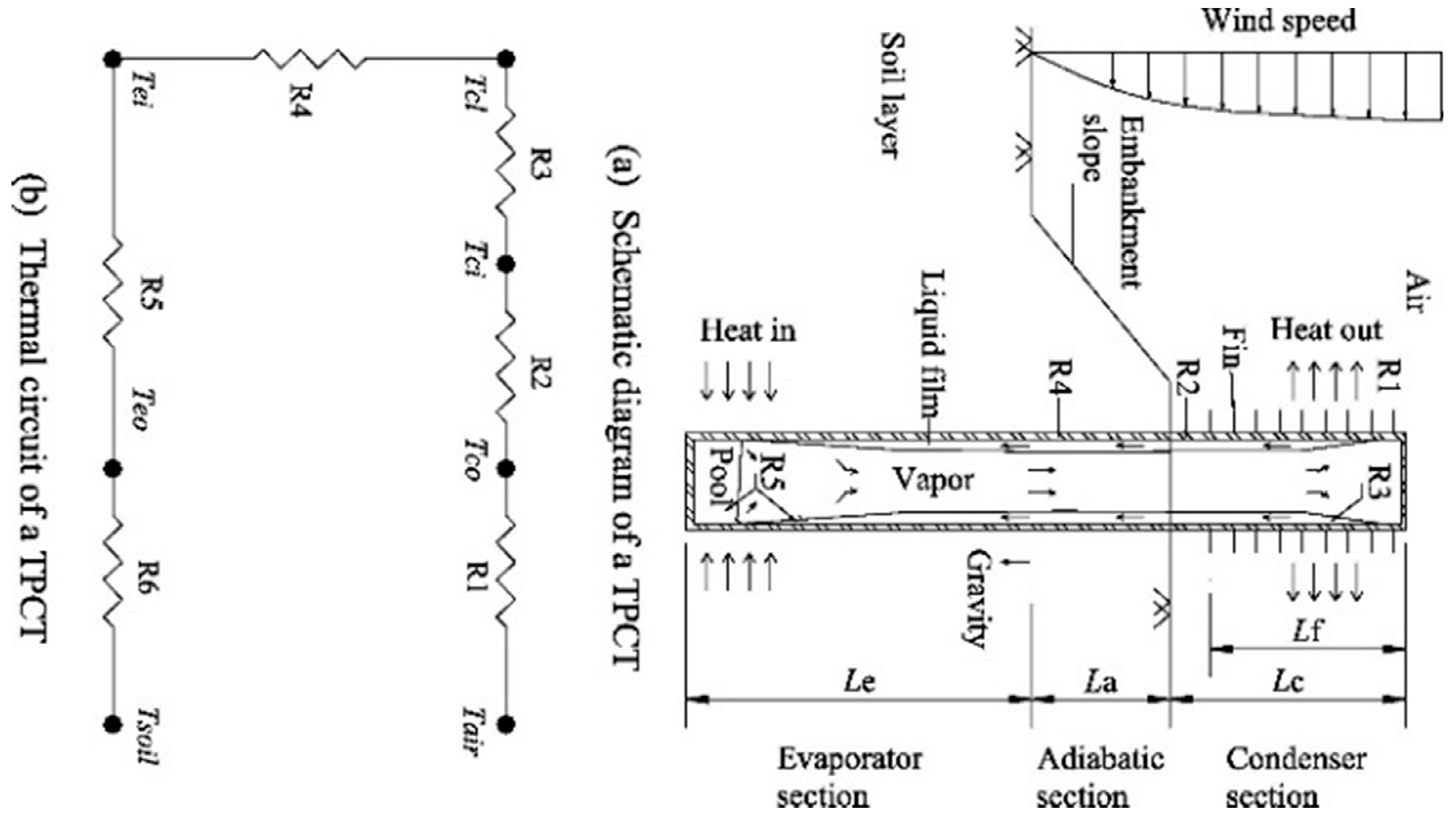
| Section | Thermal Resistance | Convective Heat Transfer Coefficient (h) andHeat Transfer area: A |
|---|---|---|
| Condenser Section | R1 + R2 + R3: R1resistance between the air and the outer wall of the condenser: R2 for the tube wall of the condenser: R3 for the liquid film formed inner the condenser: | Nusselt theory in [134] |
| Adiabatic Section | ||
| Evaporator Section | R5 + R6: R5 for the liquid film and liquid pool in the evaporator: R6 for the tube wall in the evaporator: | [146,147] |
| Total Thermal Resistance |
| Fluid | Casing Materials Compatibility | ||||
|---|---|---|---|---|---|
| Metal | Polymers | ||||
| Aluminum | Cooper | Stainless Steel | Ferritic Steels | PTFE, PCTFE, PVDF, PA, PP | |
| Ethane | ✓ | ✓ | ✓ | ✓ | PTFE, PVDF |
| R22 | - | - | ✓ | - | PTFE |
| R410a | - | - | ✓ | - | - |
| Propane | ✓ | ✓ | ✓ | ✓ | ✓ |
| R134a | - | - | ✓ | - | - |
| R11 | ✓ | - | ✓ | ✓ | PTFE |
| Ethanol | acceptable | acceptable | ✓ | acceptable | - |
| Acetone | acceptable | ✓ | ✓ | ✓ | PTFE |
| Ammonia | ✓ | corrosive in presence of moisture | ✓ | ✓ | ✓ |
© 2019 by the authors. Licensee MDPI, Basel, Switzerland. This article is an open access article distributed under the terms and conditions of the Creative Commons Attribution (CC BY) license (http://creativecommons.org/licenses/by/4.0/).
Share and Cite
Badache, M.; Aidoun, Z.; Eslami-Nejad, P.; Blessent, D. Ground-Coupled Natural Circulating Devices (Thermosiphons): A Review of Modeling, Experimental and Development Studies. Inventions 2019, 4, 14. https://doi.org/10.3390/inventions4010014
Badache M, Aidoun Z, Eslami-Nejad P, Blessent D. Ground-Coupled Natural Circulating Devices (Thermosiphons): A Review of Modeling, Experimental and Development Studies. Inventions. 2019; 4(1):14. https://doi.org/10.3390/inventions4010014
Chicago/Turabian StyleBadache, Messaoud, Zine Aidoun, Parham Eslami-Nejad, and Daniela Blessent. 2019. "Ground-Coupled Natural Circulating Devices (Thermosiphons): A Review of Modeling, Experimental and Development Studies" Inventions 4, no. 1: 14. https://doi.org/10.3390/inventions4010014