1. Introduction
It is essential for civil engineering structures to be reliable and durable. However, after years of service, many structures show severe deterioration. The operational service lifetimes of structures (e.g., bridges, elevated roadways, tunnels, etc.) can be extended significantly by advanced methods of monitoring that lead to proactive and directed maintenance programs [
1]. The condition of civil structures should be monitored carefully and nondestructively to confirm that their integrity is maintained and to enable that specific damage is identified and quantified at the earliest stages of deterioration so that repairs can be implemented quickly and cost-effectively. It is, therefore, important to accurately and autonomously detect strain fields which occur in civil engineering structures such as buildings, skyscrapers, dams, power plants, etc. [
2]. To identify deterioration and impact-force damages, structural health monitoring (SHM) techniques that are reliable, cost-effective and easy to implement are desired. The techniques of optical fiber sensors (OFS) for structural health monitoring have been proposed and used extensively over the past decades, owing to their well-known advantages such as immunity to electromagnetic interferences (resulting from lightning strikes), robustness in chemically aggressive environments, compact sizes, light weight structures, potential low costs, ease of integration into structural components, and the possibility of distributed sensing over long distances [
3].
A number of optical fiber sensors for structural health monitoring have been proposed, such as fiber Bragg grating (FBG) sensors [
4,
5] and Fabry–Perot interferometric (FPI) sensors [
6,
7]. Both sensors are currently used to measure static and dynamic strains for monitoring civil structures. Although FBG sensors and FPI sensors can deliver useful and interesting physical data that is correlated with local behavior near the sensor element, they are still point sensors and might neglect essential information at remote locations where degradation is occurring. Degradation of civil structures occurs through the formation and propagation of localized cracks. The displacement, strain, or acceleration at a particular sensing point is insensitive to cracking unless the point is very close to the fracture zone [
8,
9]. In contrast, distributed optical fiber sensors (DOFS) provide an important advantage over point sensors since they can detect changes occurring over a spatial zone within a large sensing region. The DOFS have attracted considerable interests in health monitoring of civil structures. For instance, intensity-based [
10] or loss-based [
11,
12] optical time domain reflectometry (OTDR) methods have been presented for crack detection in concrete structures; Brillouin scattering based optical time domain reflectometry (BOTDR) [
13,
14] or Brillouin optical correlation domain analysis (BOCDA) [
15] techniques have been widely employed for strain measurements in reinforced concrete structures, especially because they are capable of being deployed in large-scale civil structures; Rayleigh scattering based optical backscatter reflectometer (OBR) [
16] or optical frequency domain reflectometer (OFDR) [
17,
18] techniques have been proposed for strain measurements in concrete structures with high spatial resolution on the scale of centimeters.
DOFS are easily integrated into host structures to produce so-called smart structures or to form a nervous system but, there is a need to look into implementation and deployment issues related to the degree of ruggedness of these DOFS when embedded in host structures. Compared with concrete or mortar structures in civil engineering applications, composites or steel materials have a smooth surface where reliable bonding to the sensor is easily achieved. Moreover, for these cases, DOFS also experience a uniform strain transfer function when subjected to external loading. And, the bonding of the DOFS to the material surface is not in danger of failure for high levels of loadings as the DOFS can easily follow the strain in the material [
19]. However, the application of DOFS to civil structures with coarse-grain compositions requires addressing two important challenges. Firstly, these civil structures may experience a break or debonding of the optical fiber due to their inherent roughness. Secondly, these civil structures usually crack at very low levels of loading, which may lead to a strain field discontinuity. Also, optical fibers are subjected to breakage during transportation and installation in the host structures. Bare optical fibers are not suitable for being directly embedded in civil structures with coarse grain compositions without proper adhesion and protection. Some attempts have been made to provide certain protective encapsulation or packaging for OFS. Steel tubes or stainless-steel housing-based designs are used to package FPI and FBG sensors for monitoring concrete structures [
20,
21]. Because it is complicated to multiplex FPI and FBG sensors for quasi-distributed measurements, the steel tube housing-based design is not suitable for real-case applications. Yasue et al. presented a simple solution to some of these problems by bonding the optical fiber to the surface of the test material and performing strain measurements with a BOTDR system [
22]. However, attaching the optical fiber to the rough surfaces of civil structures cannot reveal the real distribution of strain fields and will easily lead to a debonding issue. Zhao et al. proposed a fiber coil method by winding the optical fiber around polished steel rebar and measuring the strain distribution of the rebar with a BOTDR system [
23]. Quiertant et al. presented a scheme for bonding an optical fiber to rebar directly and then measuring strain with an OBR unit [
16]. The important issue for the bonding scheme of an optical fiber to rebar is that the existence of the coating on the optical fiber results in a difference between the strain experienced by the rebar and the strain sensed by the DOFS [
24]. Lanticq et al. [
25] and Lesoille et al. [
26] both proposed a composite-made wave-like packaging method that enabled continuous bonding between the optical fibers and the concrete structures for distributed strain measurements. However, a major drawback of wave-like and other packaging schemes is that they inadvertently create a non-uniform strain transfer function between the host structure and the guest optical fiber sensor. A non-uniform strain transfer function is typically difficult to calibrate, and it leads to unreliable strain measurements. To overcome the general deleterious problem of a non-uniform strain transfer function, we desire a packaging scheme that includes a protective feature, an anti-sliding feature, and a uniform strain transfer function.
In this paper, we report for the first time to our knowledge, a novel screw-like package design for use by an embeddable sensor for civil engineering applications that affords a protective feature, eliminates sliding, and provides an inherently uniform strain transfer function. We designed a plastic screw-like package structure that functions as the external protective housing for the optical fiber sensor. The bare optical fiber is embedded into a groove of our screw-like package structure using a rigid adhesive. Our robust packaging scheme provides sufficient protection to bare optical fibers from breakage, eliminates sliding between the plastic screw-like package structure and the host optical fiber, and the packaged sensor accurately and optimally transfers strain fields from civil structures to the optical fiber. Importantly, our screw-like structure has equal cross-sectional areas perpendicular to and longitudinally-disposed along the central screw axis so that the embedded optical fiber faithfully meters the strain field distribution in the host structure. A distributed Rayleigh scattering-based optical frequency domain reflectometer (OFDR) system interrogates our packaged sensor. We demonstrate the experimental validation of the novel distributed optical fiber sensor embedded into a cement mortar structure for strain measurements. The spatial resolution of strain measurements along the length of the embedded optical fiber was 7 mm.
2. Materials and Methods
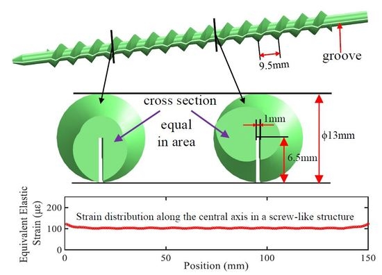
Figure 1 illustrates our plastic screw-like structure with a length of 185 mm and an outer diameter of 13 mm. As illustrated in
Figure 1a, a groove (depth of 6.5 mm, width of 1.0 mm) is machined along the central axis of the screw-like structure. The pitch of the screw thread is 9.5 mm. A bare single-mode optical fiber (made from a single 125 µm-diameter silica strand with a 62.5 µm-thick polyimide coating) was embedded and rigidly secured in the machined groove of our screw-like structure using epoxy resin (ITW Devcon, Danvers, MA, USA). The machined groove is used to fully embed the bare optical fiber in the screw-like structure, with epoxy resin used as an adhesive and filler. Importantly, the epoxy resin we chose has very similar material characteristics when compared to the material of the plastic screw-like structure. Therefore, the groove section of the screw-like structure can be treated as a uniform object with similar material characteristics.
Figure 1b,c depict two cross-sections located at two representative positions along the length of the screw-like structure. For a distributed strain sensor for civil applications, preventing stress concentrations and debonding of the sensor are big challenges. In our screw-like structure, all cross-sections perpendicular to the longitudinal axis are equal in area. This important design feature of our sensor reduces concentrations of stress and realizes a uniform strain transfer function from the surrounding test structure material to the optical fiber. Existing packaging structures, such as the wave-like structure [
25,
26] have different cross-sectional areas along the central axis. Any packaging structure with different cross-sectional areas perpendicular to the optical fiber axis will create a non-uniform strain transfer function between the host structure and the optic fiber sensor.
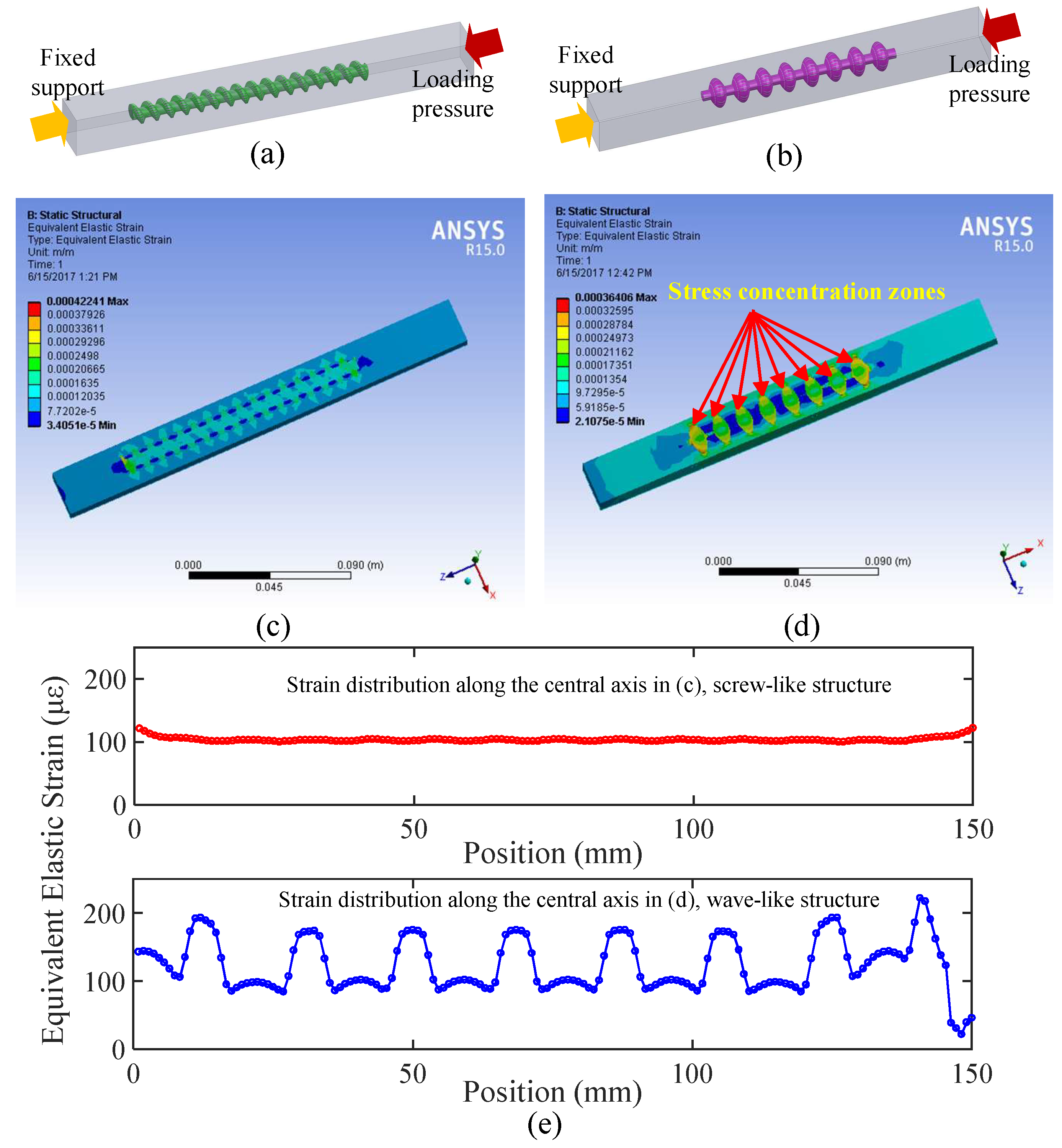
For purposes of demonstration, we compared the behavior of the screw-like structure to the wave-like structure, which was used as a reference. Computer simulations were carried out using finite element analysis (analyzed using ANSYS Workbench 15.0, Canonsburg, PA, USA).
Figure 2a,b depict the two physical models (modeled individually using Solidworks 2014, Waltham, MA, USA and assembled in Workbench). Both models consist of a mortar brick specimen (size: 25.4 mm × 25.4 mm × 254 mm) with a sensor device embedded along the long axis. We compared the proposed screw-like structure, embedded in a mortar brick specimen, to a wave-like structure whose dimensions were identical (external and internal diameters of 6.5 mm and 3.3 mm, respectively, and a length of 150 mm). We performed a static structural analysis on both of the models. Importantly, we regarded the contact surfaces of the package structure and the mortar brick specimen as perfectly bonding for both models. As shown in
Figure 2a,b, a fixed support was applied at one endface of the mortar brick specimen, and a uniform pressure of 3 MPa was applied as a load to the opposite endface.
Figure 2c,d schematically illustrate the equivalent elastic strain distribution of the screw-like structure and the wave-like structure, respectively. The equivalent elastic strain distributions along the central axis in
Figure 2c,d were plotted in
Figure 2e. Note that all assumptions for the computer simulations remained consistent in both models. From the computer simulation results in
Figure 2c,e, we learned that the equivalent elastic strain is distributed uniformly along the central axis of the screw-like structure. However, the strain distribution for the wave-like structure illustrated in
Figure 2d,e clearly show a concentration of strain at each wave crest zone. Thus, the computer simulations show that the strain distribution along the wave-like structure is not uniform, in other words, the wave-like structure transformed a uniform strain distribution that was defined in the host structure into a non-uniform strain distribution, which would be metered by the optical fiber sensor. Our proposed screw-like structure, together with an optical fiber embedded inside the groove can serve as an excellent and faithful candidate for a distributed strain sensor for civil applications.
To support the contention for an increase in the radial extension to sensing strain, we need to perform a calculation using ANSYS for a cylindrical structure of the same outer diameter as the outer diameter of the central cylindrical portion of the screw-like structure and compare the radial extent for sensitivity to strain for both structures. Similar to the previous simulations, the size of the mortar square rod is 25.4 mm × 25.4 mm × 254 mm, and the length and outer diameter of the embedded optical fiber are 150 mm and 250 µm, respectively. In addition, all the assumptions for the computer simulations remained consistent with the previous two models. As shown in the following
Figure 3a, a fixed support was applied to one endface of the mortar square rod, and a uniform pressure of 3 MPa was applied as a load to the opposite endface. The equivalent elastic strain distribution of the bare optical fiber with different contact conditions are schematically illustrated in
Figure 3b,c. From the simulation results, we learned that the equivalent elastic strain is distributed uniformly along the central axis of the bare optical fiber no matter whether the contact condition between the mortar specimen and the bare optical fiber is set as “bonded” (100%) or “fractional” (fractional coefficient, 50%). However, in our experiments (demonstrated in Figure 6a), due to the imperfect interfacial bonding between the bare optical fiber and the mortar specimen, the measured strain values obtained from the embedded bare optical fiber are lower than the well-packaged sensor. In addition, no clear evidence of a crack in the strain data can be found for the mortar specimen with the directly embedded bare optical fiber.
A Rayleigh scattering-based optical frequency domain reflectometry (OFDR) method interrogated our packaged distributed strain sensor. The Rayleigh backscattering originates from the random fluctuations in the index profile along the optical fiber and can be modeled as a long, weak FBG with random periods. The Rayleigh backscattering spectrum shift in OFDR [
27,
28] forms the basis of signal processing for distributed strain sensing in our experiment. The strain variation causes modifications to the local Rayleigh backscattering, which cause a shift in the Rayleigh backscattering spectrum. We can detect the local spectral shift by cross-correlation to realize the strain measurement. Firstly, the reference and measurement signals with different strain values are acquired separately, then the signals from the optical frequency domain are converted to the spatial domain by employing a fast Fourier transform. Secondly, a sliding window with a width of ΔX is used to select the local Rayleigh backscattering. To increase the frequency resolution, the local Rayleigh scattering signal in the spatial domain is zero-padded after applying a window function. Thirdly, the selected local Rayleigh backscattering signals are converted back to the optical frequency domain by employing an inverse fast Fourier transform. Fourthly, a cross-correlation analysis is performed between the reference and the measured Rayleigh backscattering spectra to obtain the spectral shift. The spectral shift is then used to calculate the strain value.
3. Validation Experiments
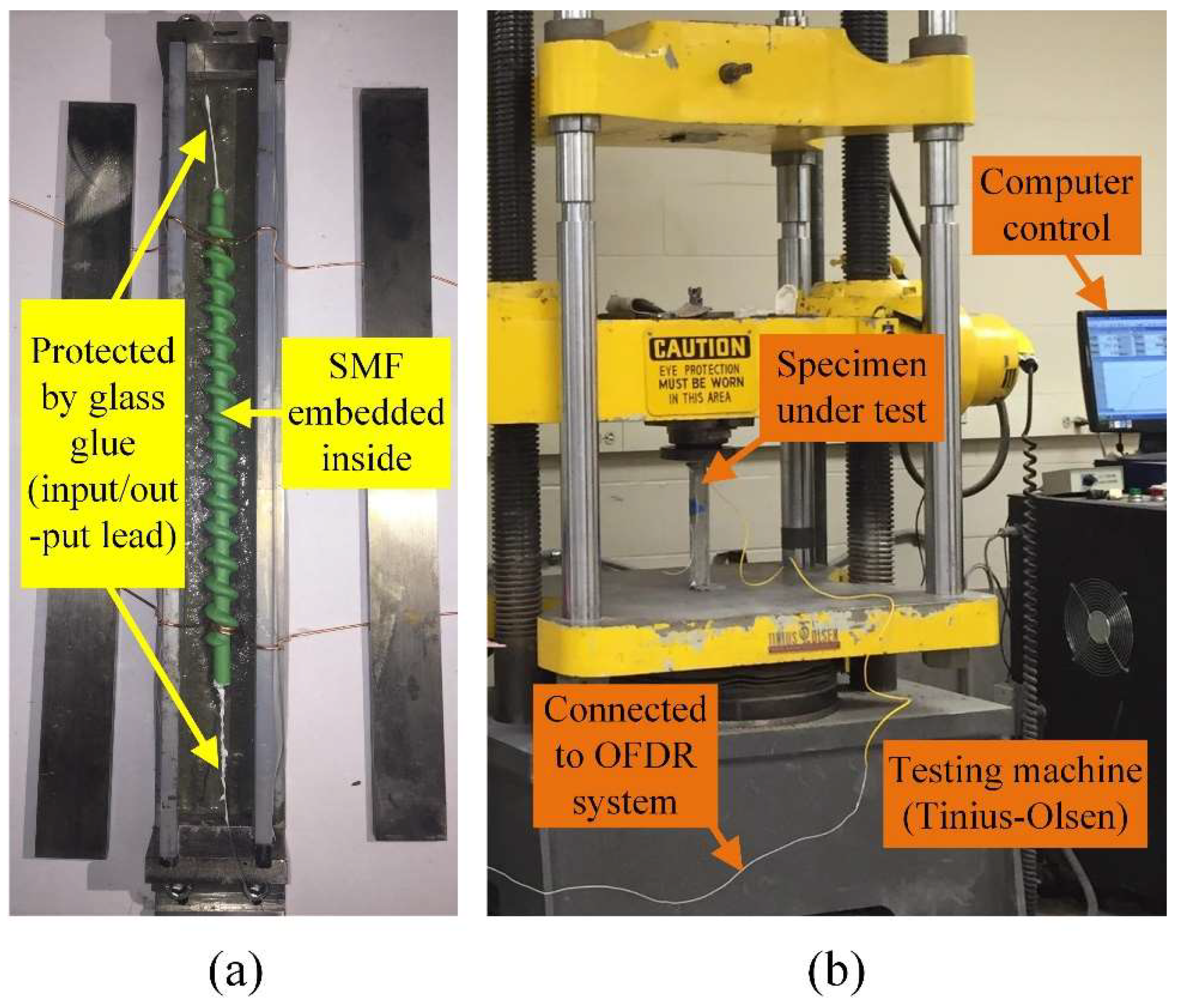
The strain response of the screw-like package structure was tested by embedding it in a cement mortar brick specimen and by applying compressive loads at a constant rate using a testing machine. Before embedding the sensor in the mortar brick specimen, a conventional single mode optical fiber (SMF-28) was positioned in a groove along the central axis of the screw-like package structure and rigidly affixed by filling the groove with epoxy resin (ITW Devcon, Danvers, MA, USA. The epoxy resin was used not only to protect the bare optical fiber from direct forces but also to ensure that no sliding occurs between the embedded optical fiber and the plastic screw-like structure. As shown in
Figure 4a, input/output leads of the optical fiber were protected by adhesive glass glue (DAP, Alex Plus, Baltimore, MD, USA. The packaged sensor was embedded in a cement mortar brick specimen with dimensions of 25.4 mm × 25.4 mm × 254 mm during the casting process. The mortar brick specimen was prepared using cement (Sakrete Portland Type-I, Charlotte, NC, USA), tap water, and sand with a weight ratio of 1.0:0.5:2.81. As illustrated in
Figure 4b, the mortar brick specimen was tested for compressive loads on a hydraulic Tinius Olsen tension/compression machine (Horsham, PA, USA) with a capacity of 98,800 kg. A desktop computer with MTestW software (Huntington Beach, CA, USA) controlled the Tinius Olsen machine. Two loading platens were used to apply the load to the two loading faces of the mortar brick specimen. The mortar brick specimen was placed on the bottom platform of the Tinius Olsen machine, which served as the lower platen. The upper, circular loading platen was attached to the upper crosshead of the Tinius Olsen machine. It is noteworthy that the faces of the mortar brick specimen that were pressed were equipped with stainless steel blocks to provide flat loading surfaces. Before loading the mortar brick specimen, the loading platens were cleaned of any debris. The Tinius Olsen machine was programmed to apply a displacement at the controlled rate of 1.6 mm/min. Actually, we stop at each loading step and wait for at least one minute before we move to the next loading step. Therefore, the loading rate was set to a relatively low value.
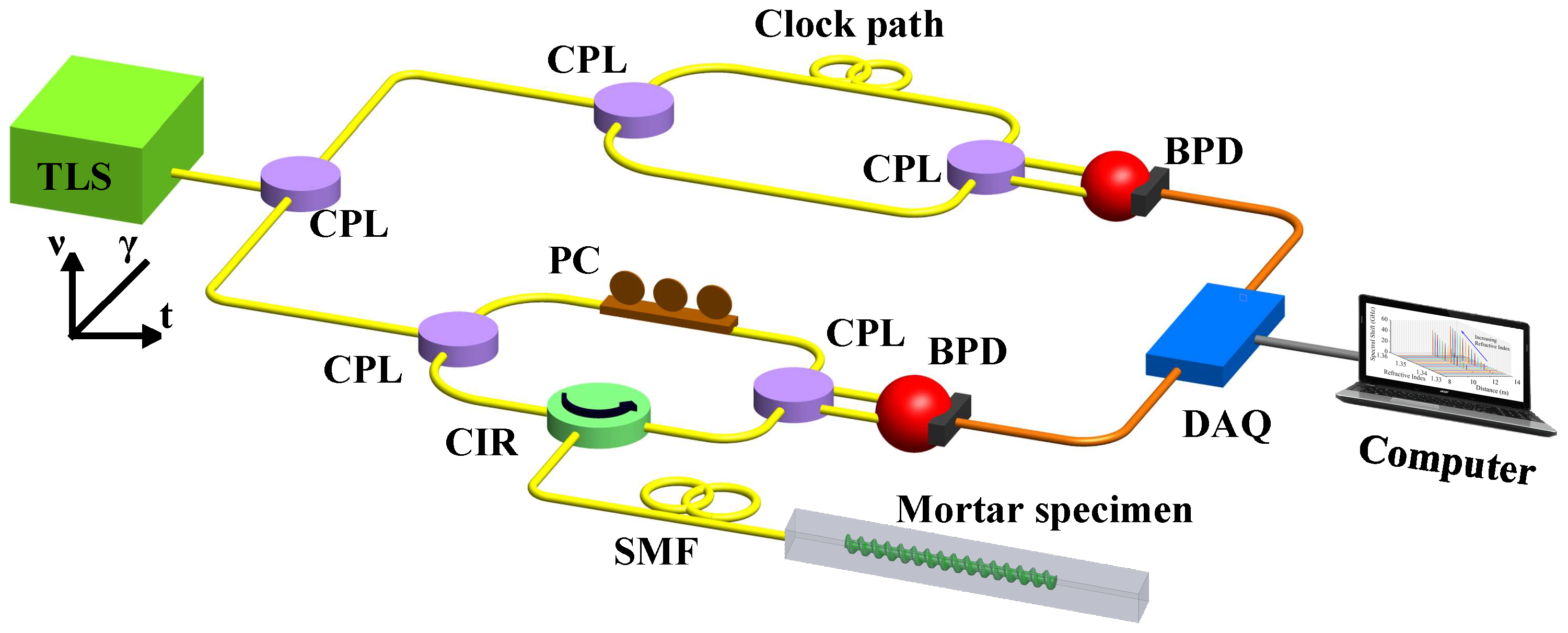
Distributed strain measurements were performed using an OFDR system.
Figure 5 shows the schematic diagram of the distributed OFDR experimental setup. The light source for the interrogation system uses a tunable laser source (TLS, Agilent 81680A, Santa Clara, CA, USA). The tuning speed, tuning range Δ
ν, and starting wavelength of the TLS were 5 THz/s (40 nm/s), 2.5 THz (20 nm), and 1525 nm, respectively. A coupler splits the light from the laser into two paths. One path leads to the auxiliary interferometer (a Mach-Zehnder interferometer). It provides an external clock to trigger the data acquisition card, which samples the interference signal with equal optical frequency spacings to reduce the nonlinearity of the frequency tuning of the TLS. The other path is the main interferometer. The fiber under test (FUT) in the main interferometer was an 8 m long standard SMF, which includes the embedded portion of the optical fiber as shown in
Figure 5.
We also tested another mortar brick specimen with a bare fiber directly embedded inside the mortar in our series of experiments.
Figure 6 shows the distributed strain measurement results for the two mortar brick specimens. The actual lengths of the optical fibers embedded inside the mortar bricks were both 189 cm. We applied the same compressive loads (0-7145N) with five loading steps to both mortar brick specimens.
Figure 6a,b depict the load-induced strains along the central axis of the embedded optical fibers. The spatial resolution for both tests was 7 mm. The spatial resolution can be calculated through our OFDR system. In our OFDR system, a theoretical spatial resolution Δ
Z can be expressed as:
, where
c is the speed of light in a vacuum (3 × 10
8 m/s),
n is the refractive index of the optical fiber (1.46), Δ
ν is the tuning range of the laser source (2.5 THz). So, the theoretical spatial resolution Δ
Z is calculated as 40 µm. During our signal processing for strain measurements, a sliding window with a width of Δ
X (Δ
X = N·Δ
Z, N is number of data points, chosen as 175, therefore Δ
X = 7000 µm) is used to select the local Rayleigh backscattering signals along the optical fiber. The data for a single stain measurement point is obtained from a 7000 µm segment of the optical fiber and assigned to the center of the range, resulting in a stain measurement uncertainty of ± 1 µε. Selection of a greater spatial resolution (e.g., 1 mm) requires a smaller number of data points but results in a greater uncertainty for the strain measurement.
4. Discussion
Interestingly, the measured strain values for each loading step obtained from the embedded bare optical fiber without packaging are lower than the well-packaged sensor (bare optical fiber embedded in the screw-like package structure). This observation is primarily due to the imperfect interfacial bonding between the bare optical fiber and the mortar brick specimen. The sensor in the plastic screw-like package structure shows a larger absorption of the host material strain and offers a better strain transfer than the directly embedded optical fiber. In
Figure 6b, the crack position in the mortar brick specimen appeared when the applied load was large enough. However, no clear evidence of a crack in the strain data can be found in the mortar brick specimen with the directly embedded bare optical fiber (after a large load was applied) as shown in
Figure 6a, even though a crack was visible to the human eye (as shown in the inset photograph of
Figure 6a). The series of plots in
Figure 6b reveal variations of measured strains (range: −211 to −365 microstrains) that depict a uniform spatial strain pattern reported by the embedded section of the packaged optical fiber sensor. The pattern provides the necessary and sufficient evidence that our sensor functioned in a well-behaved and expected manner as an increasing force deformed the mortar brick specimen, coincident with the axial coordinate of the packaged optical fiber sensor. The expected bending deformation is mirrored by the data curves. When a crack failure occurred (confirmed by the visual evidence of a crack in the mortar brick specimen), the data plots for the applied forces of 5711 and 7145 N showed spatially-localized features that are reasonably attributed to a crack (see purple and green curves in
Figure 6b). Importantly, the crack event was monitored by our packaged sensor for a range of strain measurements that are well below the known upper limit (8000 microstrains) for reproducible strain measurements by optical fiber sensors [
29,
30,
31,
32]. Furthermore, had our packaged sensor failed, it would not have been possible to obtain the measured spatially-disposed strain curves (the sensor would have gone dark). It is worth mentioning that no hysteresis exists in our designed sensing device. Prior to conducting the strain measurements, we had performed a reproducibility test on a bare fiber over a range of a 0.3% (3000 µε) length change and found 100% reproducibility (zero hysteresis). Our experimental findings were consistent with many reports in the literature regarding bare glass optical fibers.
As we have shown in our designed plastic screw-like structure employed in the experiments reported in this work, the pitch length of the screw thread is 9.5 mm, and the core diameter of the structure is 3.3 mm. The ratio between the pitch length and the core diameter in our designed structure is about 2.88. With these designed parameters for the screw-like structure, we have verified that our packaged sensor not only eliminates slippage in the mortar brick specimen but also maintains sufficient strength to transfer imposed forces on the mortar brick to the optical fiber with a uniform transfer function. Therefore, the pitch length of the screw thread, the core diameter of the structure, the screw thread depth, and the Young’s Modulus of the screw-like package material as well are several key factors that mitigate slippage and ensure accurate strain measurements must be considered when replacing the mortar with other structural materials, such as concrete with coarse gravel, for instance. Hence, it is reasonable to optimize the screw-like package structure for a matrix of cement and coarse gravel by increasing the pitch length of the screw thread and increasing the screw thread depth to match the average size of the gravel. However, we cannot decrease the core diameter (or increase the external diameter) of the screw-like package without taking into account the requirements for the physical strength and the size limitations of the host material structures. Our screw-like package sensor affords a wide range of values for the design parameters to accommodate different host materials in real field applications.
Considering a potential field application with large structures, we have to compensate temperature effects for our screw-like structure sensor. We are working on packaging solutions with our screw-like structure for realizing temperature compensation. For instance, when an optical fiber is positioned in a groove along the central axis of the screw-like package structure, only half of the optical fiber is affixed by filling the groove with epoxy resin. Therefore, the loose optical fiber that does not experience applied strain can be used for temperature compensation. We believe there must be many other packaging solutions for temperature compensation. We will present our new packaging design with temperature compensation in a subsequent report.
Additional and extensive collection of data useful for accurate calibration and detailed design specifications for variations of our novel screw-like packaged sensor is within the purview of the R&D efforts of a company tasked with the manufacture and commercialization of a final sensor product. We would encourage and support such appropriate efforts, especially as we seek to commercialize our device.
5. Conclusions
In conclusion, we report a screw-like package structure design used for embedding an optical fiber sensor for distributed strain measurements in civil engineering structures with fine and coarse grain compositions. Our optical fiber sensor, which is packaged in a unique screw-like package design, has three advantages. Firstly, the plastic screw-like structure serves as an external protective package for an optical fiber sensor. The bare optical fiber is embedded into a machined groove along the central axis in our screw-like structure using a suitable rigid adhesive. Secondly, the threads of the screw-like package design prevent it from sliding in the host structures. Thirdly, and most significantly, the screw-like package structure design provides an inherently uniform strain transfer function. Computer simulations were carried out using finite element analysis to compare the behavior of the screw-like structure to the commonly-used wave-like structure. The embedded optical fiber sensor faithfully meters the strain field distribution in the host structure because our screw-like package structure has equal cross-sectional areas perpendicular to and along the central screw axis. A distributed Rayleigh scattering-based optical frequency domain reflectometer system interrogated our packaged sensor. We demonstrated the experimental validation of the distributed optical fiber strain sensor embedded in a cement mortar brick specimen with a spatial resolution of 7 mm. Our plastic screw-like package structure, together with an optical fiber embedded inside a central groove axis can serve as an excellent candidate for an accurate and robust distributed strain sensor for civil engineering applications. Most importantly, the salient contribution of our work to the structural health monitoring community is the novel and unique geometry of our screw-like package design for strain sensing that provides an inherently uniform strain transfer function. We note that multiple types of sensor elements (e.g., optical fiber, coaxial cable, wire, piezoelectric, accelerometer) can be embedded in our screw-like package and used for monitoring the structural health of national infrastructures.


