1. What Is the Potential for Future Innovation
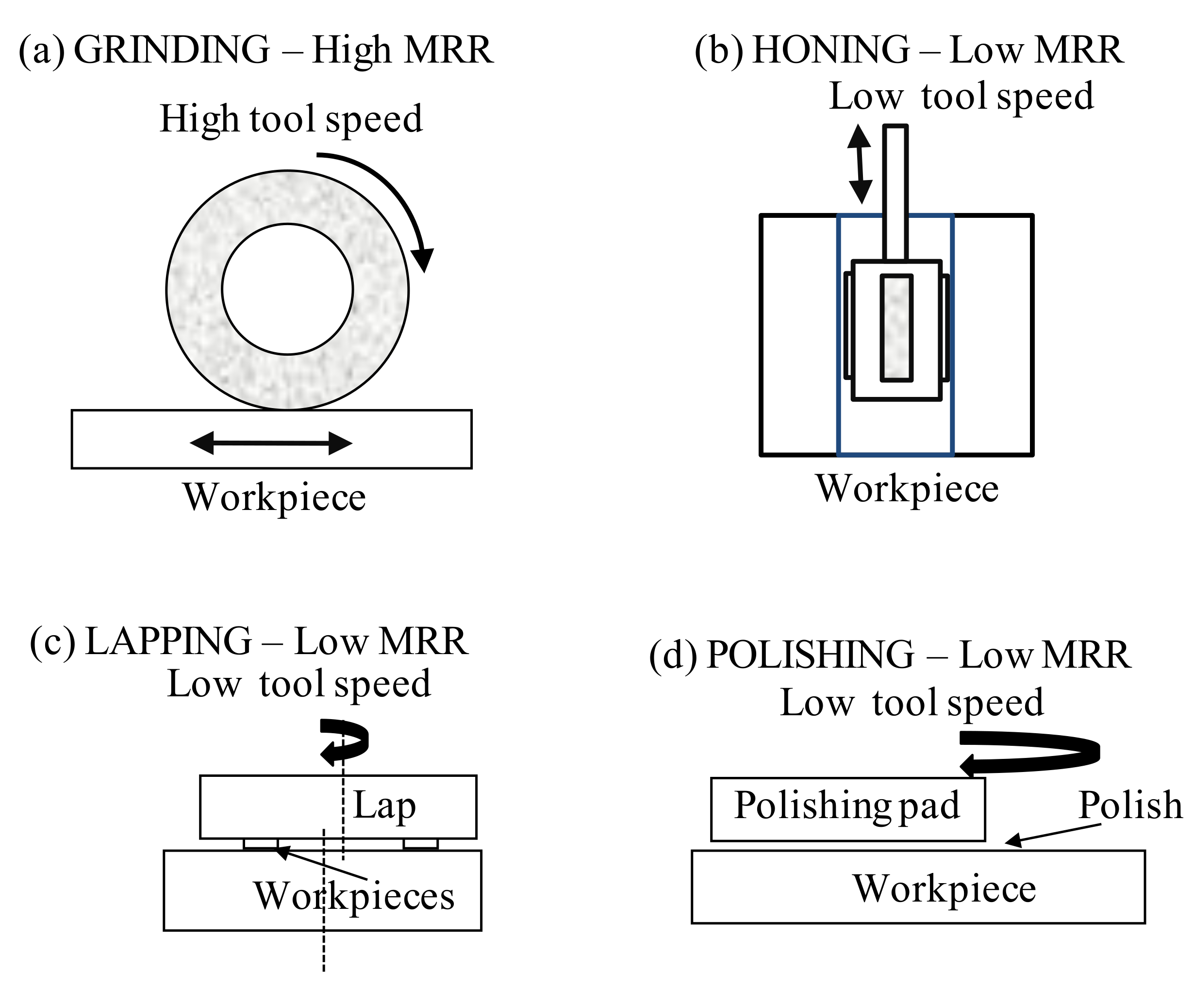
In a narrow context, grinding is the removal of material using a high speed abrasive. In a wider context abrasive technology includes material removal using low speed abrasive. Innovations that allow high speed processes to replace low speed processes achieve higher removal rates as explained in more detail by Rowe [
1]. For example, the introduction of new grinding techniques such as electrolytic in-process dressing using metal-bonded wheels make it possible to mirror-grind hard silicon wafers with greatly increased removal rates [
2].
Examples of low and high speed abrasive processes are illustrated in
Figure 1. Higher tool speeds allow much higher removal rates and have therefore been one of the main drivers of technological advance. However, this single predominant trend has required many other advances in machine tool design, grinding wheel design, and system control.
Innovations in modern grinding technology cover an immense range of scientific and industrial disciplines spanning from the interdisciplinary science of tribology and surface interactions to control systems and artificial intelligence [
1]. The subject fascinates engineers trying to reduce costs and improve manufacturing productivity within the factory environment and scientists seeking to explain complex interactions between an abrasive and a workpiece. The drivers of innovation include demands for better abrasive tools, higher precision, higher removal rates, introduction of new work materials such as aerospace alloys and hard ceramics, and demands for better surface integrity.
In recent decades, manufacturing engineers are also driven by additional needs such as to operate in a healthier environment, to eliminate toxic waste, to increase manufacturing flexibility, and to employ intelligent control of processes using modern digital technology. The potential for innovation is almost limitless depending ultimately on the engineer’s imagination. For example, lead times between processes are reduced by integrating a grinding module into a multi-process and multi-tool system. Manufacturers can also envisage employing a robotic grinding tool together with an automated optical inspection system to remove product defects within an automated machining system. Looking back over the previous century, it is startlingly obvious that the range and scope of technological development has been accelerating, giving great hope for the future.
As manufacturing technology advances, there is increasing awareness that grinding is a “strategic process” in that it is a critical process for the achievement of the best quality of parts and the lowest cost [
1,
3]. This awareness has led to the formation of specialist grinding research laboratories within a number of universities, particularly in Europe, USA, Japan, and China.
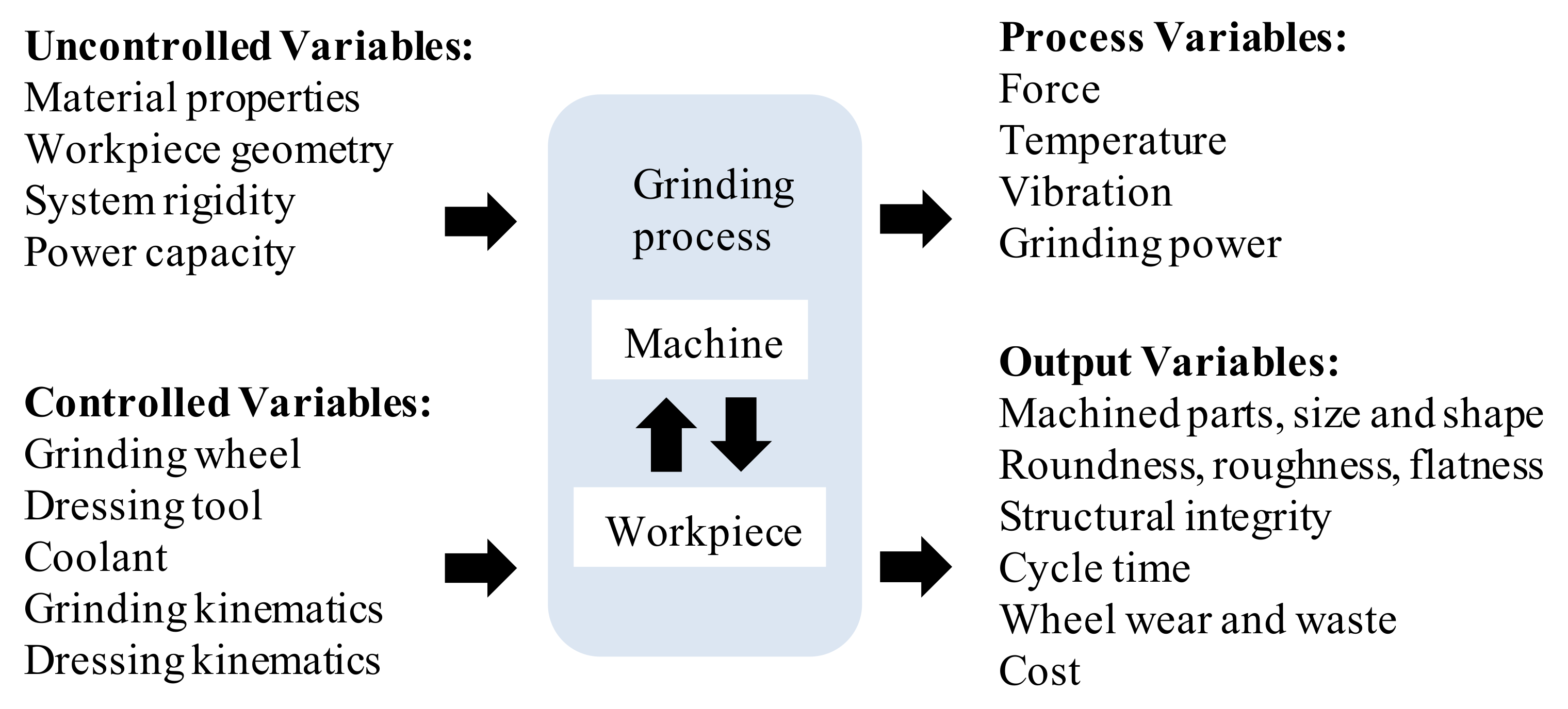
Advances are not always made by a single change of a single element of a grinding system but usually by a combination of changes affecting several elements. The main parameters the engineer has to manage are shown in
Figure 2, Chen and Morgan [
4]. Controlled variables are those inputs that are open to change either by an engineer, a human operator or by a computer controller. Uncontrolled variables are basically set values not usually continuously controlled, although potentially open to change. As the process operates, there is continuous variation in forces, temperatures, vibration, and grinding power each of which critically affects the output quality of the machined parts and costs.
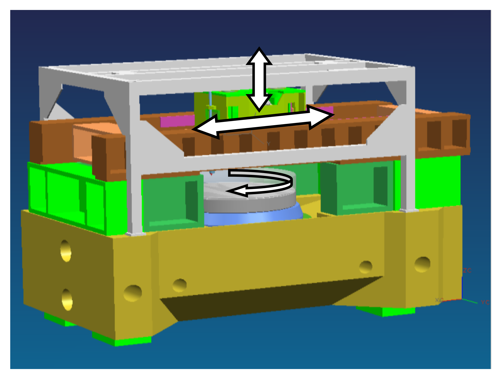
Parts to be produced vary from very large to very small and from conventional soft engineering steels to very hard steels, alloys, and ceramics. The diverse range of products required to be machined means there is a large range of grinding machines having diverse characteristics. It is not proposed to discuss differences in modern machines and applications in this paper, as it would require too much space for a single paper. However, a schematic of a special-purpose grinding machine is shown in
Figure 3 as an example of innovative designs produced to achieve high productivity in the grinding of high precision mirrors and lenses [
5]. Whereas most machines are based on an open “C” or “U” shaped structure for convenience of part-loading, a new generation of high precision machines employ a box structure to limit machine deflections. With high-precision drives and control systems, the grinding accuracy achieved was better than 1 μm form accuracy on large 1 m sized parts.
This paper reviews aspects of science and application leading to improved productivity and quality in grinding processes. Symbols and nomenclature are listed in
Appendix A.
2. Wheel Speeds, Material Properties, and Process Kinematics
It was recognized more than 100 years ago that almost every aspect of process behaviour including energy efficiency and material removal rate depends on maximum uncut chip thickness as proposed by Alden [
6] and Guest [
7]. In this respect, grinding is very little different from micro-milling, although grinding is performed at much high surface speeds of the cutting edges which affects the cutting mechanics. In simple terms,
where grit spacing
for a sharp triangular grit and
for a blunt rectangular grit as shown by Rowe ([
1], pp. 319). Increasing chip thickness increases force on the grit. Chip thickness is seen to depend on speeds, feeds, and depth of cut; also on grit spacing and on grit wear as affected by workpiece, coolant and abrasive material properties. The major difference between grinding and micro-milling is the randomness of the grit locations in the wheel surface which means the maximum chip thickness is highly variable in practice. Variation in maximum chip thickness means that not all abrasive grains cut at optimum depth. Many will merely rub on the workpiece wasting energy.
Force on the abrasive grit increases with removal rate and reduces with increasing wheel speed and contact length. However, grinding is also affected by rubbing and ploughing processes.
Figure 4 illustrates three different regimes of physical contact that take place with increasing grain penetration [
8].
Hahn [
8] showed that an abrasive grit rubbing on a ductile material with low normal force increases or reduces surface roughness without removing significant material. This abrasive action is typical of blunt grits. With further increase in normal force, a grit plastically deforms the surface causing side pile-up of material known as ploughing. With yet further increase in force or with a sharper grit, chips are formed and material is removed from the surface. Advances in grinding technology are often associated with changes to reduce wasteful rubbing and ploughing action. Innovations aim to increase the proportion of chip removal compared to ploughing and rubbing so that material is removed with minimal energy.
The transition points between these three regimes depend on various factors notably abrasive sharpness, material properties and lubrication. Processes for polishing and lapping traditionally take place predominantly in the rubbing regime, whereas precision grinding takes place in all three regimes. High energy deep grinding and cut-off operations take place predominantly in the material removal regime by chip formation for ductile materials or by crack formation for brittle materials.
It should be emphasized that energy and material removal in grinding is strongly dependent on the nature of the workpiece material. Hard materials such as cemented carbides [
9] and hard ceramics [
10] are brittle and difficult to grind. Such materials tend to exhibit a dominance of crack formation when machined but also require a very hard abrasive such as diamond. However, in many cases, it has been shown possible to grind brittle materials in the ductile mode by employing extremely small chip thickness, thus reducing the risks of weakened structures, a process pioneered by Ohmori and Nakagawa [
2].
Not all brittle materials are difficult to grind. Some materials, such as grey cast iron, are easy to grind as shown by low energy required compared with grinding hard steels.
Since many parameters influence abrasive contact conditions, there is enormous scope for achievement of higher process efficiency and for achievement of better surface quality. Process efficiency depends primarily on the energy required to remove material. Removal rate per unit width:
Grinding energy per unit unit volume of material removed is known as specific energy:
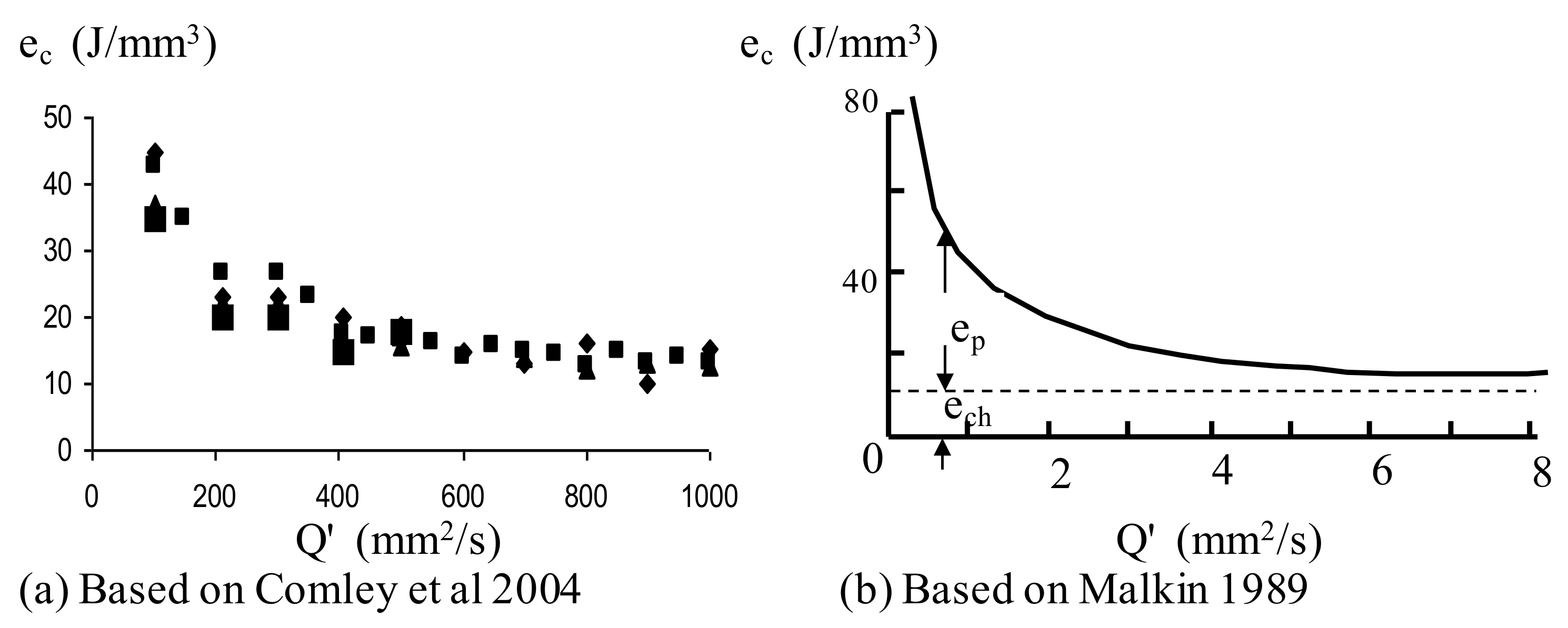
Figure 5 shows typical relationships between
and
.
Figure 5a based on Comley et al. [
11], shows results for high efficiency deep grinding of camshaft webs at very high removal rates using a sharp electro-plated superabrasive cBN wheel.
Figure 5b for surface grinding is based on Malkin [
12], and shows results for low speed shallow grinding at 30 m/s using conventional wheels to grind the material AISI 1095HR. Comparing
Figure 5a,b, it is seen that huge increases in removal rate of up to 100 times have been achieved in high efficiency deep grinding (HEDG) using high-speed superabrasive wheels together with effective total system design.
Both sets of results show that increasing removal rate by increasing
and
, reduces specific energy asymptotically. The asymptotic energy level is typically of the order of 10 J/mm
3 but can even be as low as 5 J/mm
3, depending on the work material and abrasive [
13].
Malkin [
12] concluded that the energy carried away with the chips must be lower than the asymptotic value and that the energy corresponds to the enthalpy for the maximum chip temperature,
The energy required before steel chips start to become molten, is typically about 6 J/mm
3, approaching a value close to the melting energy of the work material. As melting temperatures are approached, the energy required to shear the material, is reduced. This process and a predominance of chip formation energy over rubbing and sliding energy provides a partial explanation for a low energy asymptote at high removal rates.
Unfortunately, a limit is found to removal rates, when the work material starts to flow into the grinding wheel surface and the abrasive action breaks down. Some materials such as inconel 718, maintain hardness at high temperatures, which makes the material difficult to grind. High forces on the abrasive grits cause rapid wear and high temperatures that increase the tendency for wheel loading. It may be necessary to reduce chip thickness by increasing wheel speed and also to ensure effective lubrication and cooling [
14].
3. Process Limits to Removal Rate in Grinding
Increases in removal rate tend to be limited by the need to maintain or improve product quality as specified for accuracy, surface integrity, and surface roughness. Relationships between quality parameters and removal rate depends on many factors such as kinematics, material properties, abrasive properties, machine stiffness, cooling, and lubrication as indicated in
Figure 2. Over the years, innovation has allowed removal rates to be increased often with improved quality as a result of increased knowledge, improved understanding of process behaviour and ingenuity employed to expand the process boundaries.
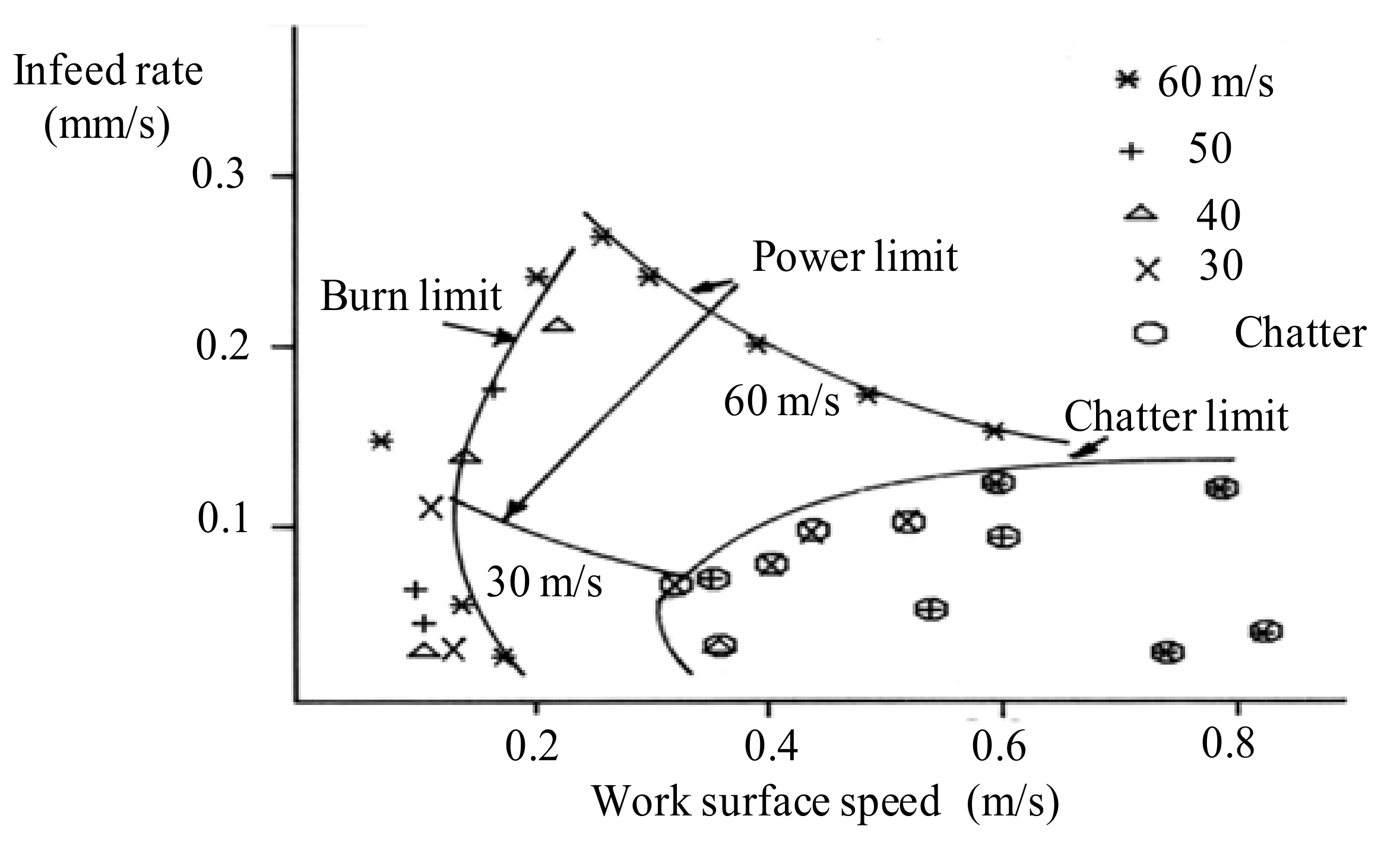
Figure 6 shows a limit chart derived for centreless grinding [
15].
Typical process limits are shown in
Figure 6, for infeed rate and work speed where removal rate increases with infeed rate
according to
in centreless grinding or
for centre grinding. The safe operating range for the particular grinding wheel, machine design, and work material is enclosed by a thermal damage boundary, the machine power limit, and the chatter limit. This chart is typical for many grinding processes although the nature of the limits may vary. For example, the power limit shown may in many cases be replaced by a maximum surface roughness limit or possibly by a size control limit. The striking feature of the figure is that the maximum infeed rate is greatly increased by increasing the wheel speed from 30 m/s to 60 m/s. This was partly explained by the reduction in chip thickness with increasing wheel speed and corresponding reduction in grinding forces, but was also partly explained by the characteristics of the main spindle speed controller. Much higher grinding speeds, more than 150 m/s have since been made possible by use of superabrasive wheels [
16]. It is seen in
Figure 6 that low work speeds and high infeed rates lead to burn. It is also found that chatter vibration becomes more of a problem at high work speeds. It can therefore be seen for a particular machine set-up, there is an optimum work speed where a maximum feed rate can be achieved.
4. Process Control for High Productivity and Quality, Use of Sensors, and Process Models
Process control may involve introducing variations in process input parameters to correct for quality errors such as inaccuracy, surface integrity problems due to thermal damage, excessive roughness, and excessive vibration. With repeated batch manufacture of a product, it is possible to apply process control changes between parts produced. Sometimes, with larger workpieces or longer grinding cycles, it may be necessary to apply corrections within a part cycle.
Unfortunately, it is not usually possible to employ data directly from charts such as
Figure 6 for process control. This is because the process boundaries shift with time depending on various factors such as grinding wheel wear, workpiece hardness, redressing kinematics, and dressing tool wear. An alternative is to employ process sensors and process models to monitor process changes and to predict necessary changes to bring a process back into a safe operating region.
A major advance in grinding process control in the 20th Century was the introduction of precision diameter gauging linked to CNC control. Typical results for precision grinding with diameter gauging are shown in
Figure 7. Typical results for a constant feedrate system are shown in
Figure 7a. Employing a 60 s cycle time, it was possible to hold size for successive parts within approximately 1 μm. However, with an adaptive control system, it was possible to predict a new target feed position and to vary the spark-out dwell period for each part [
17]. A similar size range was achieved but mean cycle time was reduced from 60 s to 37 s,
Figure 7b. With adaptive control, removal rate was substantially improved without sacrificing accuracy.
Using adaptive control, it is necessary to use sensors that can detect whether the system is being maintained within an acceptable operating region while increasing the control variable towards the process limit. Various sensors have been used, in addition to the standard position sensors employed for CNC, the most common being a power sensor which is reasonably inexpensive and easy to incorporate into a system without requiring a dynamometer fixture. Other sensors, including size sensors, force sensors, acoustic emission sensors, and Barkhausen noise sensors may be employed to check for safe operation. To overcome many problems, such as burn or chatter, it may be necessary to reduce work speed or to reduce infeed rate or possibly to redress the grinding wheel. Some decisions require an intelligent input either from a human operator or possibly from AI software incorporated into the control system. For process control, it is often necessary to employ a process model to relate a measured variable to the required control variable. For example, to adaptively control spark-out dwell period, as in
Figure 7b, the best way was to determine system time constant from the measured power [
18].
For prevention of thermal damage in industrial processes, a power sensor is usually employed, either in conjuction with a thermal model or without a thermal model [
1,
3]. Of course, there are other decisions that affect the onset of thermal damage such as redressing a worn wheel or even replacing the grinding wheel with a more efficient wheel.
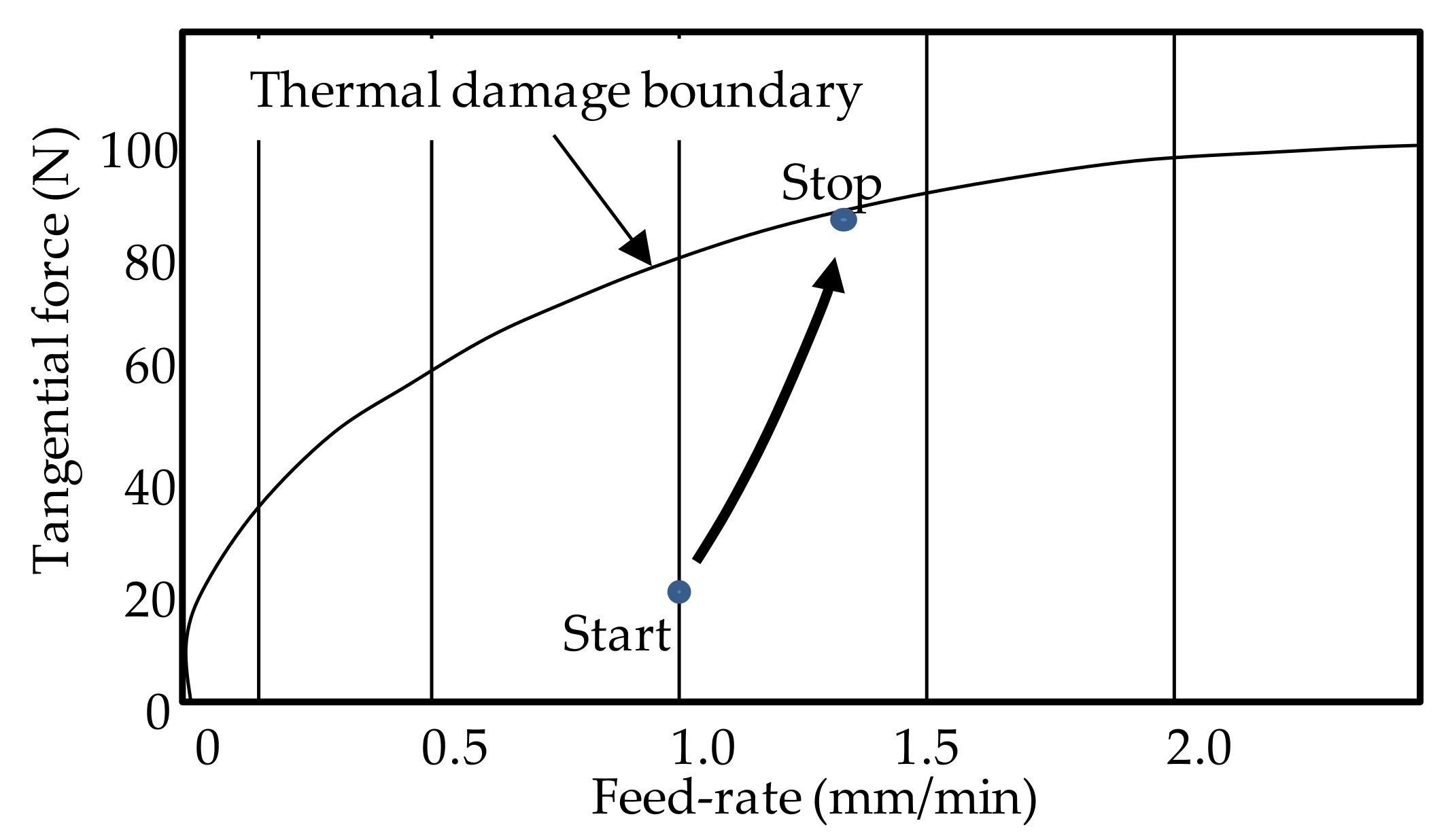
The onset of thermal damage correlates with an excessive grinding power for the particular grinding conditions or an excessive force level. In
Figure 8, using a force sensor, feed rate is increased in small steps up to the limit for thermal damage, Steffan et al. [
19]. The application of post-process Barkhausen noise measurement for correlation with temperature modeling is described by Sridharan et al. [
20]. This latter paper introduces the concept of modelling and correlating more than one measured variable for improved reliability of prediction. The use of multiple sensors will no doubt be a trend for the future.
5. Temperature Rise Modeling
Thermal models may be used as a basis for process control, Rowe [
21]. Temperature rise is critical for workpiece surface hardness, surface roughness, material phase changes, and onset of tensile residual stress. The Rowe thermal model has been validated for a range of grinding processes including conventional shallow grinding, creep feed grinding, and HEDG [
21].
The model can be derived from heat balance of the heat flows in the contact zone. Four heat flows make up the total heat flow, Werner et al. [
22]. The total heat flow
results from the grinding power
dissipated within the grinding contact area
and is defined as
. The four heat flows take place to the workpiece, the abrasive grains, the chips and the grinding fluid. The chip energy
, see
Section 2, is immediately carried away from the contact area and plays no further part in heat partitioning. The remaining heat
, is shared at the grain and workpiece rubbing interface according to Hahn [
8] and also according to the more refined model of Rowe et al. [
21,
23]. The heat flow into the workpiece at the grain contact is given by
. Some heat
is conducted out again by the fluid within the grinding contact area. The temperature rise, of the workpiece is therefore given by the Rowe thermal model [
1,
21], as follows:
where,
has a value between 0 and 1 depending on the grain conductivity, the workpiece thermal properties, the grit contact area, and the wheel speed. For conventional abrasives when dry grinding steels, a typical value is 0.85, and for superabrasive cBN, a typical value is 0.46. For diamond abrasive a typical value is even lower, showing a great advantage of superabrasives for avoiding large temperature rise.
The terms
and
are convection factors for the workpiece and the fluid respectively. The convection factor for the workpiece is given by classical heat transfer theory and defined as
given by,
where
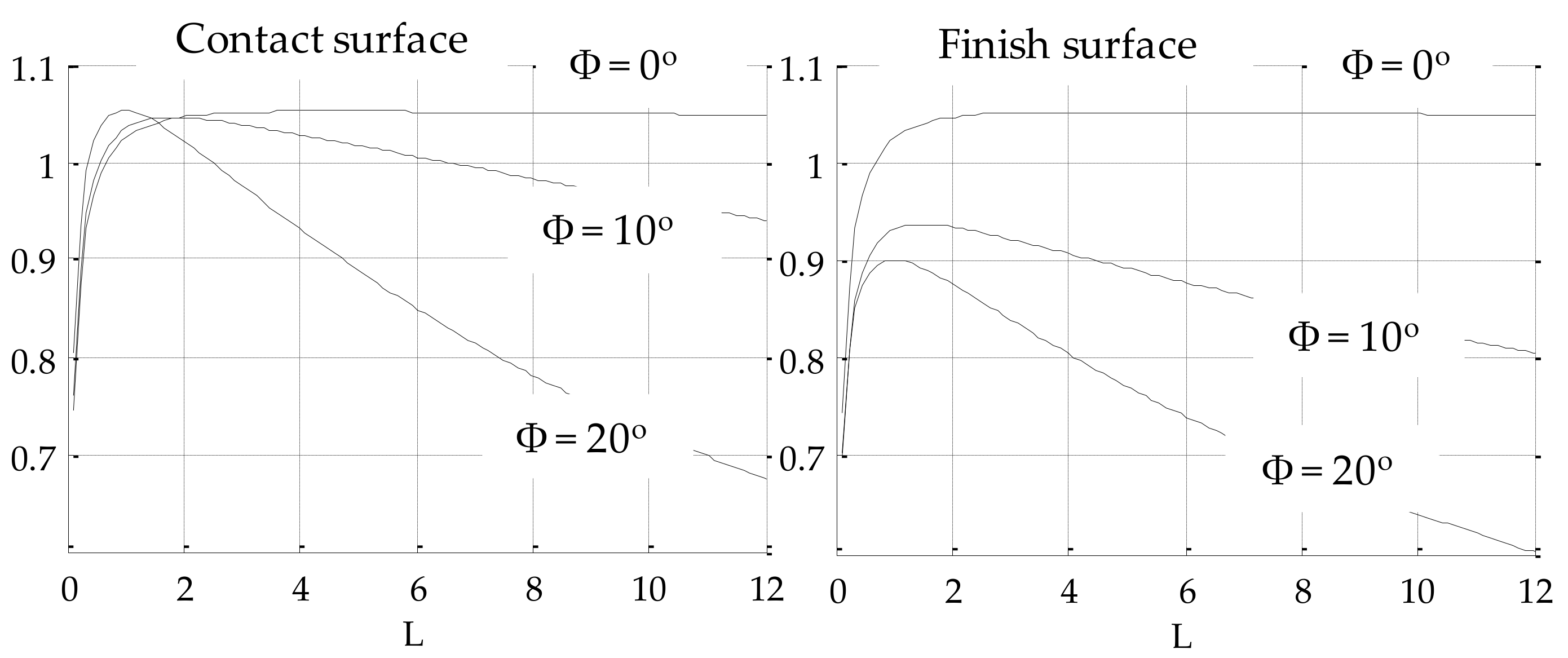
for conventional speeds. For shallow cuts and deep cuts and other values of speed, values of
are given in
Figure 9 and in the literature [
1,
21]. Temperatures on the finish surface are seen to be lower than on the grinding contact surface for deep grinding.
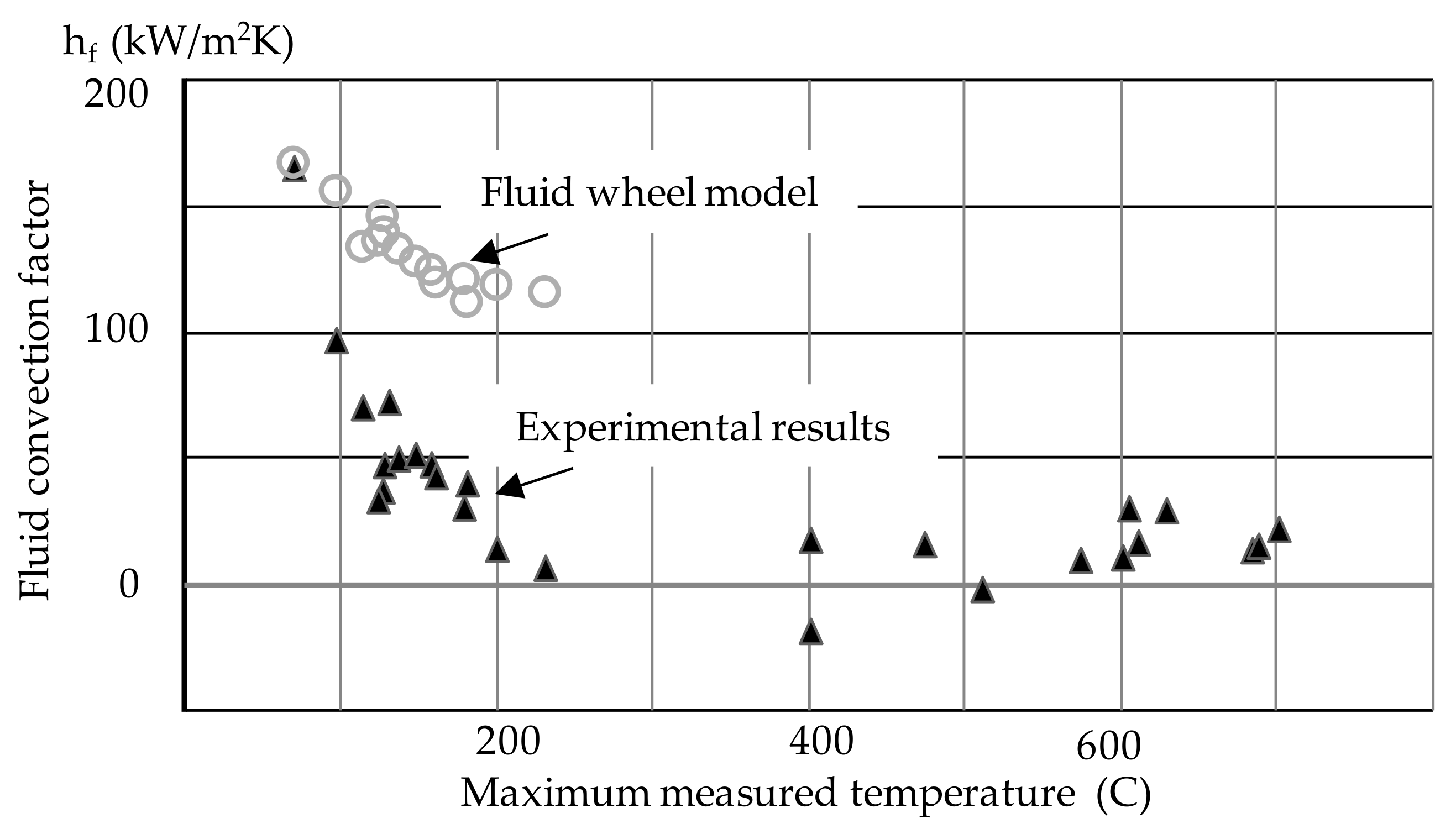
It can be seen that a process model for fluid film convection is highly desirable to form a link between grinding energy and workpiece temperature rise. This is still a subject of research. An expression sometimes used to estimate fluid convection assumes the pores of the wheel are filled with cold fluid throughout the contact arc and cools the workpiece as though it was a “solid-fluid wheel”. The convection factor from this assumption is given by
. Correlation with experimental results,
Figure 10 shows reasonable agreement in low temperature grinding below the fluid boiling temperature [
24]. It is also found that fluid convection can be much higher than previously realized. In practice, the convection factor rapidly reduces towards zero if the fluid boils.
Simplifications, for example, ignoring fluid convection, conduction into the wheel, and chip energy, over-estimate temperature rise and grossly over-estimate temperature rise in some cases to the point that steel would apparently reach 10,000 °C or more. A simplified but inaccurate assumption that all heat enters the workpiece, gives the misleading expression .
6. Grinding Fluids and Fluid Delivery
Grinding fluids play several important roles in a liquid-based wet grinding process. As seen in the previous section, a grinding fluid can play a valuable role in reducing grinding temperature by providing surface cooling within the grinding contact area. A major early review of friction, cooling, and lubricaton in grinding lists 160 research papers (Brinksmeier et al. [
25]). Other roles are played by the grinding fluid including keeping the machine cool, keeping the body of the workpiece cool and flushing away the grinding debris. This latter role is particularly important in high removal rate grinding and in mirror finish grinding. Grinding swarf can clog a grinding wheel or be pulled into the grinding contact area causing surface damage [
26]. The grinding fluid also serves a physical–chemical lubrication role in the contact between the work material and the abrasive material which can be critical for avoidance of excessive grinding wheel wear and rapid onset of wheel loading [
27].
There are three primary classes of grinding fluids: (1) fluids which are mixed with water known as water-based fluids and emulsions; (2) mineral oils; and (3) synthetic oils. Within these groups there are a very diverse family of oils and chemicals selected according to the type of abrasive and the nature of the work material.
Water-based coolants have a better cooling property than oils but boil at a much lower temperature. The much reduced cooling above the boiling temperature of water based coolants is seen in
Figure 9. Water-based coolants also need to be changed frequently before excessive contamination and bio-degradation take place. Neat oil coolants have better chemical stability and are generally better for preventing subsequent corrosion of the workpieces.
Coarser grit wheels allow more fluid to circulate into the grinding contact and are generally better at maintaining the cutting efficiency of the wheel [
28]. The supply of fluid into the grinding zone is impeded however by the boundary layer that surrounds a speeding grinding wheel [
29]. The air barrier can be overcome by providing a fluid jet velocity at a similar speed to the wheel speed and an ample supply of fluid [
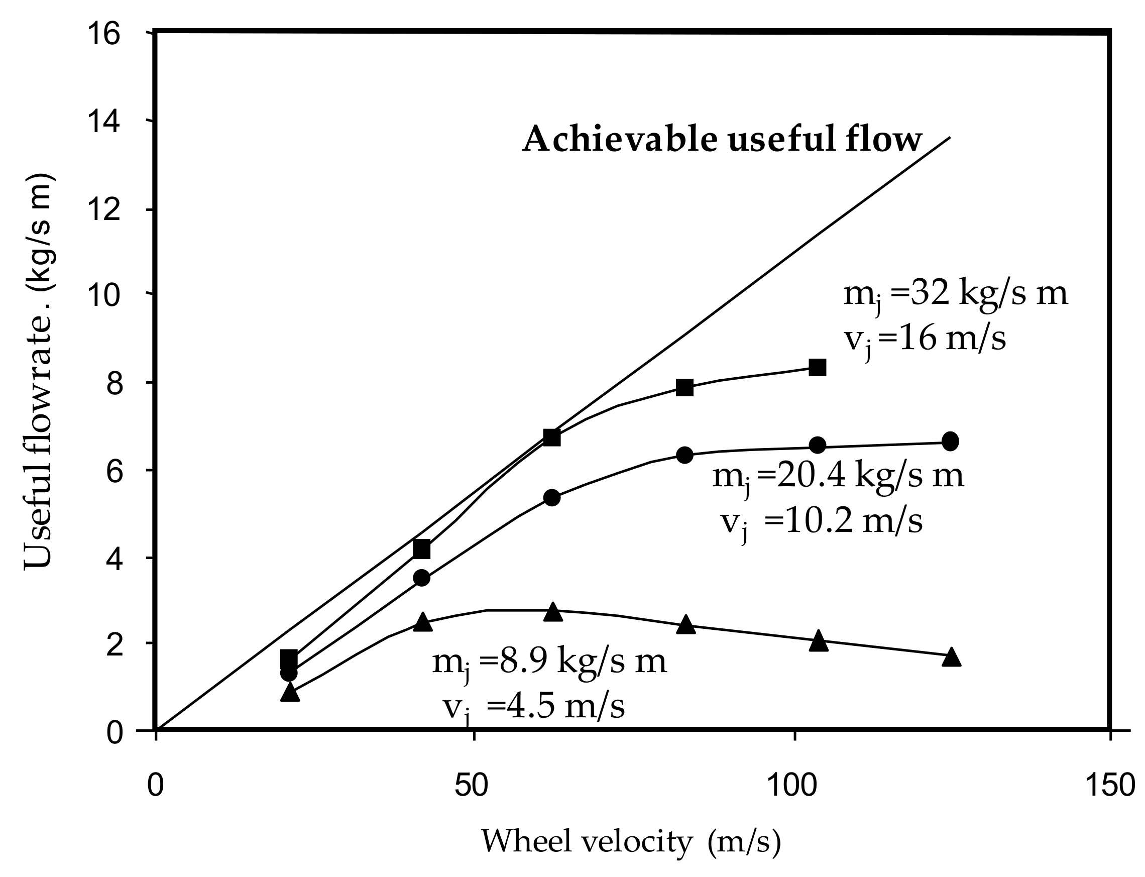
30]. However, it is wasteful to supply too much fluid as the grinding surface is unable to accommodate a large excess in the pores. This can be seen from
Figure 11. If the fluid supply is adequate, the quantity of fluid that actually enters the grinding contact increases with wheel speed. However, when the wheel speed is too high, the supply of fluid is no longer sufficient so that the useful flow levels off and will actually start to reduce. The shape and profile of the nozzle affects the effectiveness of delivery. Round nozzles are generally better than rectangular nozzles but a single round nozzle cannot cope with wide wheels. In either case, an internal concavely converging feed to the nozzle is better than a convexly converging nozzle [
31].
It is possible to roughly optimize the velocity and the flowrate required to maximize the useful flow that enters the grinding contact quite simply based on the wheel porosity, taken from the wheel manufacturer’s data, the wheel speed and the wheel width [
32]. Of course, there are times when much smaller quantities of fluid should be applied, as when finishing a product to achieve a very fine size dimensional tolerance. The fluid causes a hydrodynamic force that pushes the grinding wheel away from the ground surface. Under these circumstances, it is necessary to reduce the removal rate and reduce the flowrate to limit the hydrodynamic force.
There is a cost of fluid cooling both financial and environmental [
33]. Fluid supply requires energy to provide the high velocities and supply rates needed for high removal rate grinding at high wheel speeds. Unless the jet velocity is sufficient, the fluid jet causes a drag on the grinding wheel because the fluid has to be accelerated up to grinding wheel speed. The power required taken through the wheel drive motor can be substantial, particularly when using a shoe nozzle.
Environmental concerns have led to the introduction of minimum quantity lubrication (MQL) for grinding [
34]. MQL is usually more appropriate for low removal rate grinding since the cooling achieved is much lower than with liquid coolants. Conventional cooling delivery for grinding may involve many litres/minute whereas the delivery for MQL is usually in the form of a fine mist of esters or mineral oils injected into an air stream involving millilitres/min. Good results have been achieved for some finish grinding operations.
7. Grinding Wheels and Abrasives
Conventional grinding wheels are largely based on vitrified bond aluminium oxide abrasives or on vitrified bond silicon carbide abrasives, although other abrasives are employed for specialist purposes. For example, for flexible wheels, resin, rubber or polymer bonds are often employed. Most conventional vitrified grinding wheels run at speeds of 20–45 m/s although with rigorous attention to safety requirements, vitrified wheels can be obtained for higher speeds. Monolayer superabrasive grinding wheels, such as diamond and cBN wheels often run at much higher speeds, in excess of 150 m/s. Although, superabrasives are more expensive, much greater hardness allows these materials to achieve much longer life when grinding very hard mechanical engineering and electronic materials.
In more recent decades, there have been substantial developments in abrasive technology and wheel designs allowing very high speeds to be used as detailed by the late Mike Hitchiner formerly of Saint Gobain [
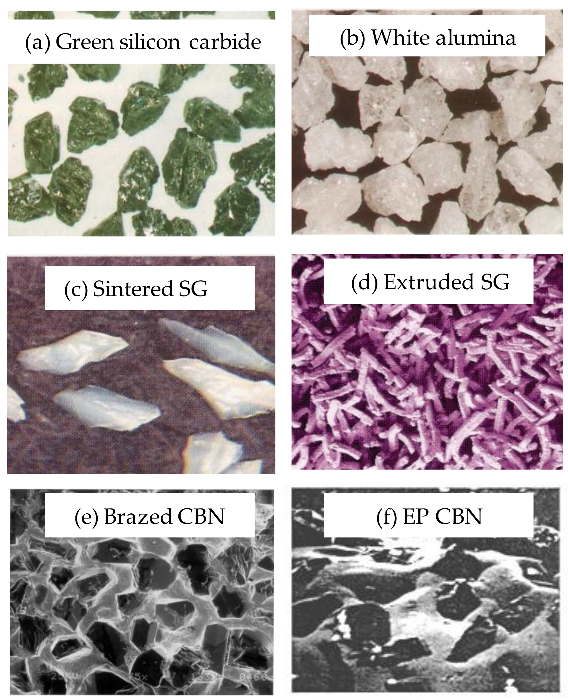
16]. Examples of conventional silicon carbide and alumina grains are shown in
Figure 12a,b, courtesy of Saint Gobain. Whereas conventional grains tend to be more blocky in shape, a new generation of more advanced sintered grain abrasives, as shown in
Figure 12c,d, have very large length to width ratio. This allows the grains to present a sharper profile when grinding and also allows harder grains to be employed to yield longer wheel life. Large length to width ratio of the grains accommodates more fluid in the pores for porosity and better cooling. The manufacturers tend to refer to such structures as superabrasive ceramics. The new structures have proven very successful in high removal rate grinding with harder materials that quickly blunt more conventional abrasives.
Figure 12e,f shows examples of brazed and electro-plated monolayer superabrasive CBN wheel structures. Monolayer wheels allow very high wheel speeds [
35]. Multilayer vitrified CBN wheels are also available as a replacement for conventional wheels. CBN is not only harder than conventional abrasives but has excellent heat conduction properties resulting in lower grinding temperatures [
1,
36].
High speed vitrified wheels requires extreme care to design for the stresses involved and avoid wheel failures [
37]. This is because the vitrified bond is the source of potential failure whereas monolayer and multilayer metal-bond wheels provide the capability to run at the highest speeds.
Diamond is harder than CBN, but is generally unsuited to grinding steels because carbon diffuses from the diamond causing rapid wheel wear. However, diamond due to its hardness has advantages for very hard materials.
Conventional vitrified bond wheels are generally dressed using diamond tools to correct the profile accuracy and to sharpen the wheel surface. Dressing time is non-productive so it is an advantage if wheels can grind for a long time before needing to be redressed [
38]. Vitrified CBN wheels may also be dressed but dressing consumes valuable CBN material. A technique to minimize the material removed in dressing and to optimize subsequent grinding performance is known as ‘touch dressing’. Acoustic emission sensors detect the instant of contact between the dressing tool and the wheel, hence allowing accurate setting of a minimal dressed depth [
39].
Monolayer CBN and monolayer diamond wheels are not usually dressed since this would damage the abrasive layer. Such wheels must therefore be manufactured with great accuracy to ensure the grains all lay at the same level on the surface. Manufacturers aim to control the evenness and circularity of the wheel to 1 micron.
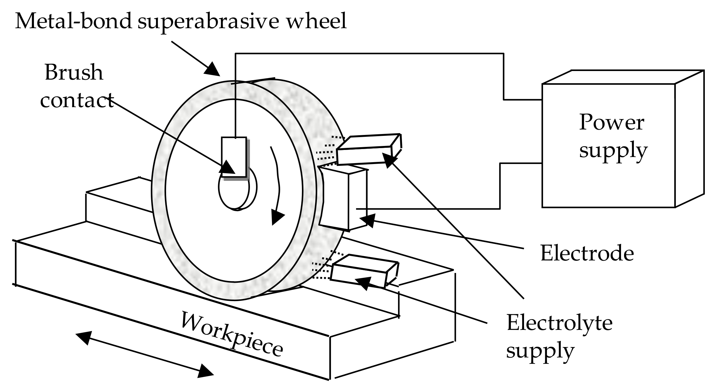
Some modern dense materials such as hard ceramics require diamond or CBN grinding because of their hardness and brittle characteristics. It is often possible to grind such materials and obtain mirror surface finishes using extremely small depth of cut. The depth of cut has to be small enough that material removal takes place primarily in a ductile mode. Large depths of cut lead to brittle mode deformation causing surface cracks and probable failure. Processes developed in recent decades involve the use of fine-grained CBN or diamond in metal-bond wheels. Dressing such wheels has been developed using electro-chemical and electrolytic removal processes. For example, a particular process known as in-process electrolytic dressing, (ELID) is employed in a grinding process to mirror-grind silicon wafers [
2,
40]. Electrolytic dressing exposes the abrasive grains and thus allows a grinding process to take place. Grinding replaces a lapping process with much improved productivity and accuracy. Basic elements of an ELID system are shown in
Figure 13.
In recent decades, a need has been apparent for grinding wheels that can grind micro-tools which may have a tip diameter of a few tens of micrometers, Ohmori et al. [
41]. Such tools have been successfully ground using the ELID process. Aurich et al., also describe the machining of micro-parts [
42].
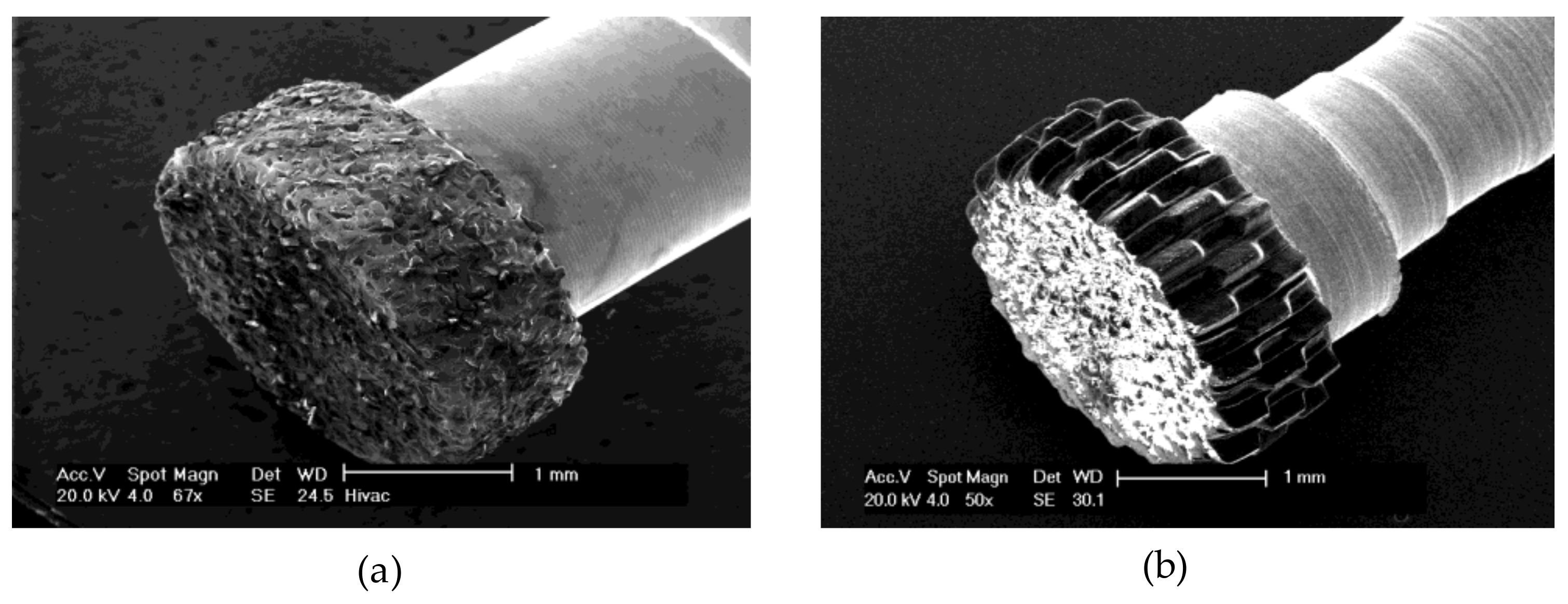
Figure 14 shows relatively large micro-tools produced by Butler-Smith et al. [
43].
Figure 14a shows a tool where fine diamond grains are secured on the surface by electro-plating and
Figure 14b shows a tool where the regular pattern of cutting edges was produced by laser ablation of solid diamond formed by chemical vapour deposition (CVD). The regularity and even spacing of the cutting edges of the laser ablated tool was said to give improved surface roughness and accuracy.
The recent rapid increase in parts produced by additive manufacturing has created a need for finishing processes that can improve the surface roughness of parts having complex geometrical shapes. An alternative to grinding using a grinding wheel is the use of abrasive mass flow processes as described by Jamal and Morgan [
44].
8. Application of Artificial Intelligence and System Integration
Modern CNC systems contain intelligent software for various functions such as position, velocity, and acceleration control. AI generally implies decision-making that is, to some extent, judgemental based on sensor input. It implies that the machine can make a decision that otherwise may require a human being. Whereas a human being may become tired, the AI machine will continuously perform repetitive tasks without human intervention, making adjustments where necessary. AI may be used to help control the grinding process by reacting to sensors within the grinding machine and measurement equipment as mentioned in
Section 4. AI analyses and translates data from measurements to make decisions such as to increase or reduce feedrate to avoid thermal damage or to initiate a change point in a feed cycle as described above or to raise an alarm call for operator intervention. The application of standard AI tools such as artificial neural networks, genetic algorithms, and case-based reasoning in grinding systems are further discussed in a review paper [
45].
With the passage of time it becomes clear, that the ability of computers to collect, process, and analyse data is becoming ubiquitous. Data can be collected and analyzed for control and scheduling of manufacture in a wider sense. For the user and indeed for the machine tool manufacturer there is the possibility to collect data concerning the need for maintenance of the grinding machine or the effectiveness of its operation, using the Internet of Things (IoT). A further way in which AI can help is to assist in selecting appropriate tools or grinding conditions for the initial process set-up. An example is the selection of an appropriate grinding wheel including wheel grade and structure using case-based reasoning [
46].
9. Conclusions
This paper reviews a selection of developments in which the application of science and ingenuity has led to new grinding processes, abrasives, tools, machines, and systems. It is shown that improved technology has yielded higher productivity and better quality across a diverse range of applications involving very large and very small products. Modern grinding technology has learned to cope with a diverse range of materials relying on new abrasive tools and various kinematic operating conditions. It is concluded that this trend will continue and that future advances in productivity will include the wider application of artificial intelligence and robotics to improve precision, process efficiency, and features required to integrate grinding processes into wider manufacturing systems and into versatile machine tools.
