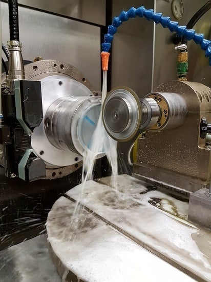
Influence of Cutting Speed on Subsurface Damage Morphology and Distribution in Ground Fused Silica
Abstract
1. Introduction
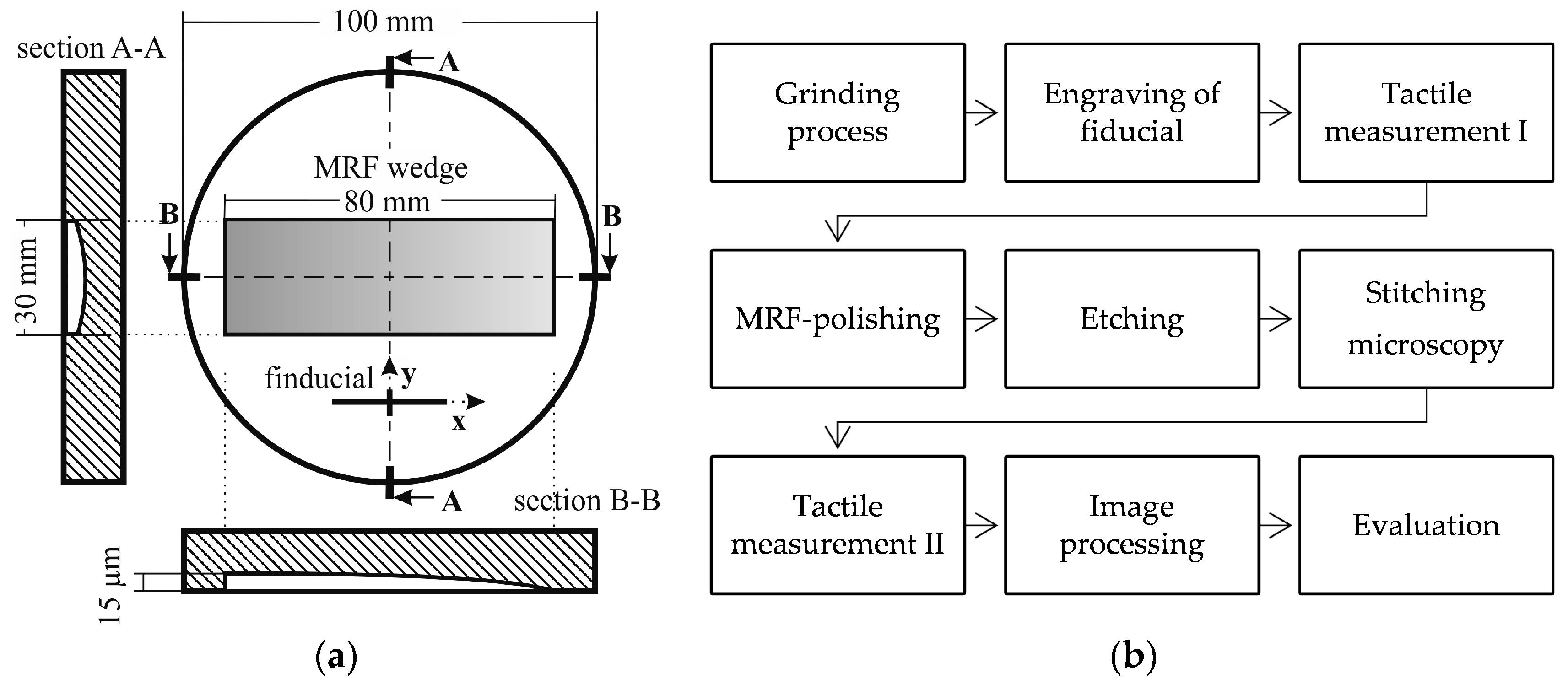
2. Materials and Methods
3. Results
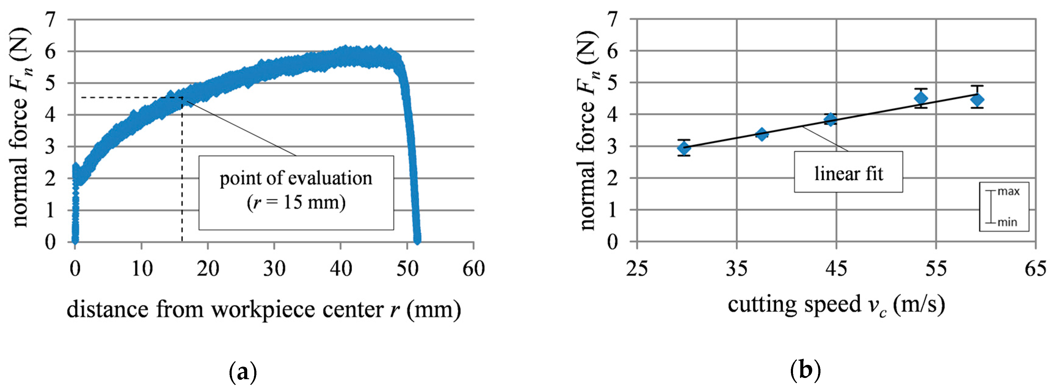
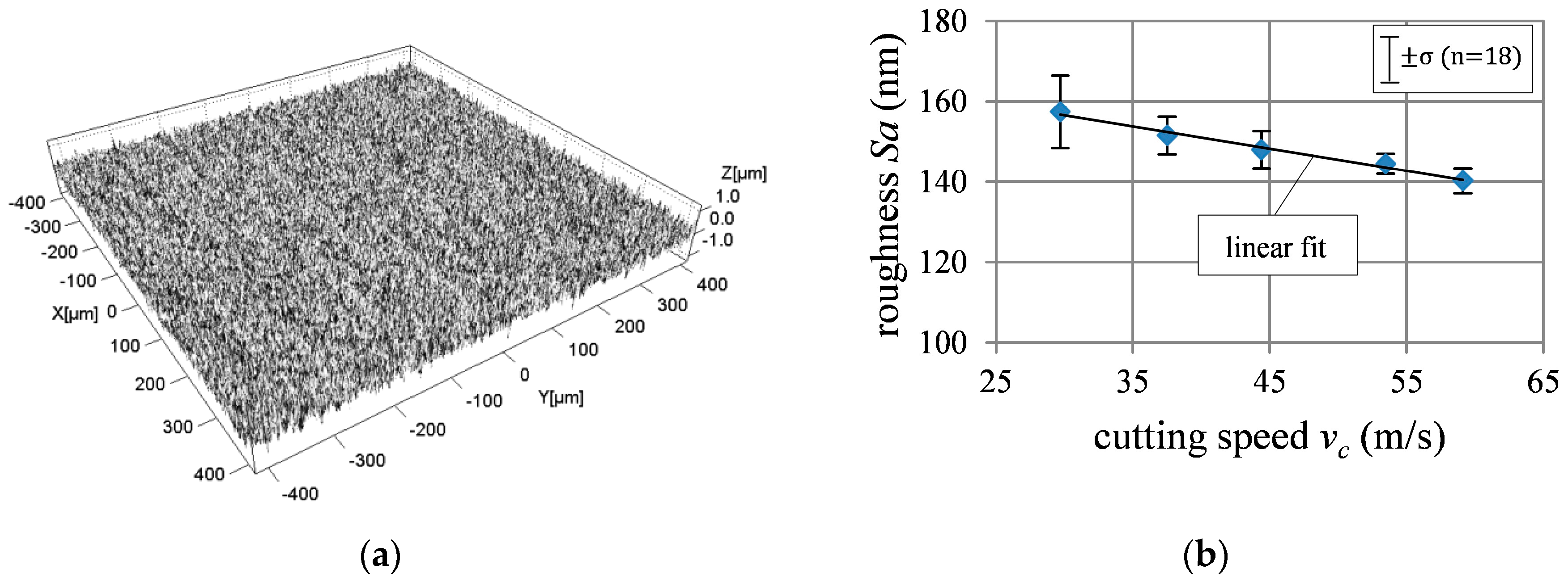
3.1. Grinding Force and Surface Roughness
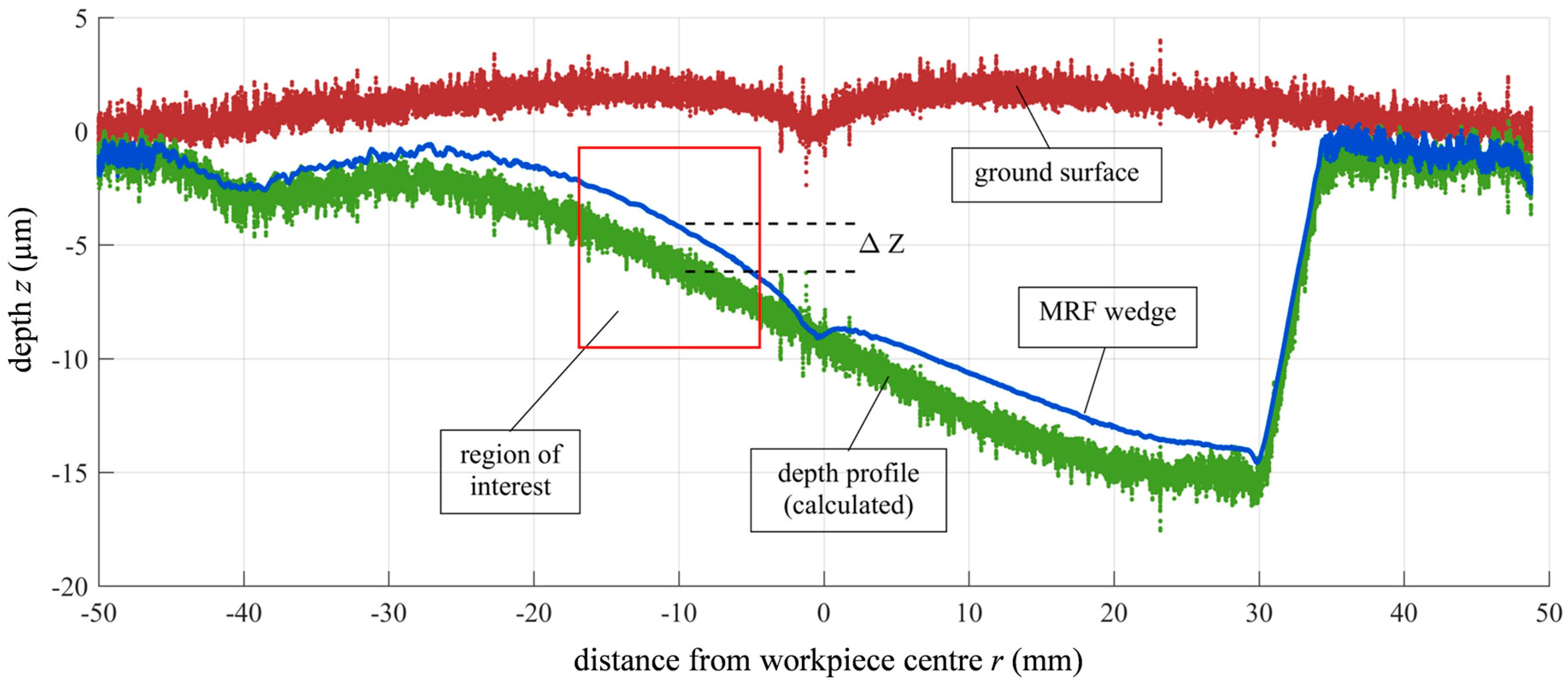
3.2. Subsurface Damage Evaluation
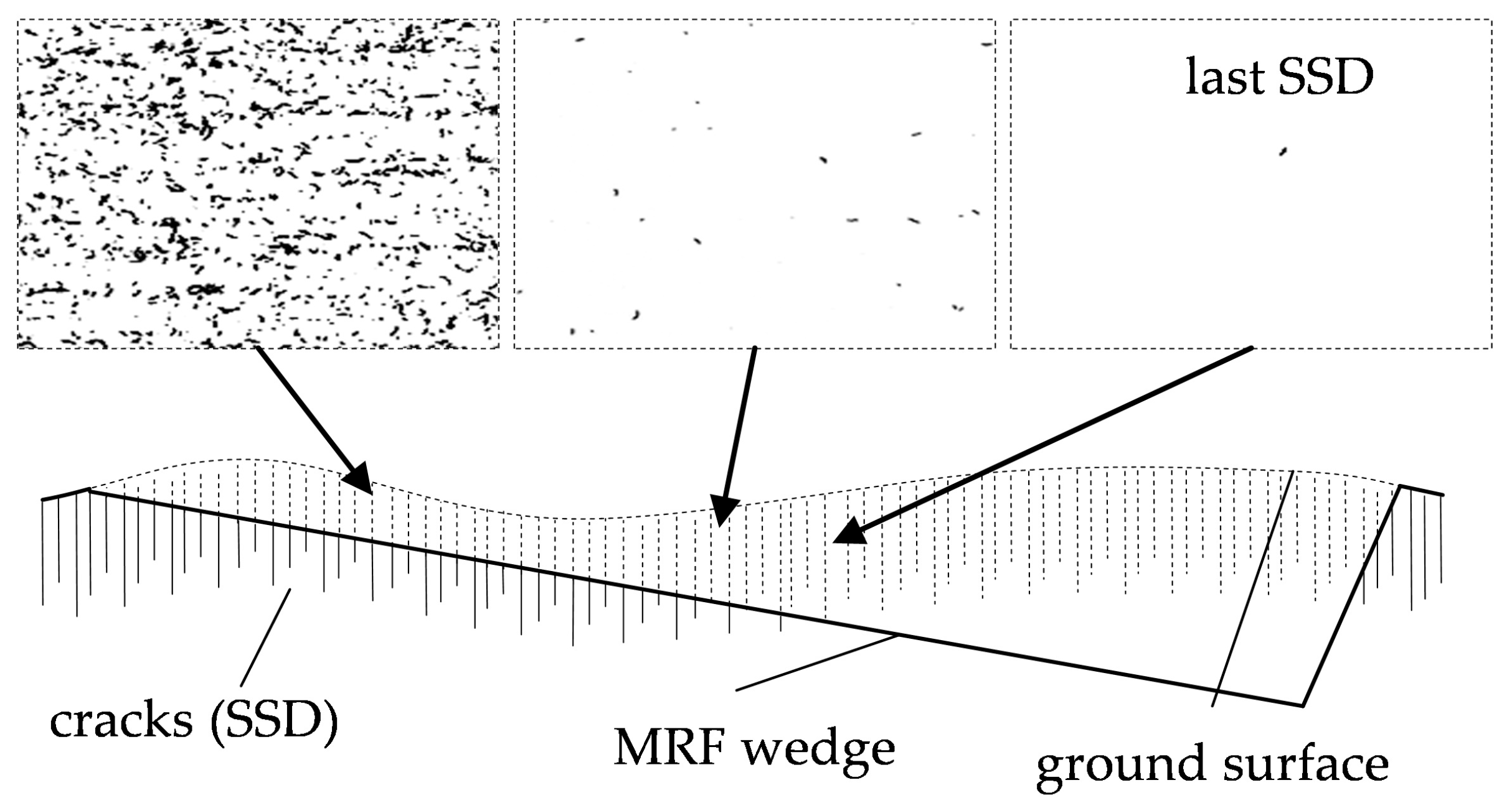
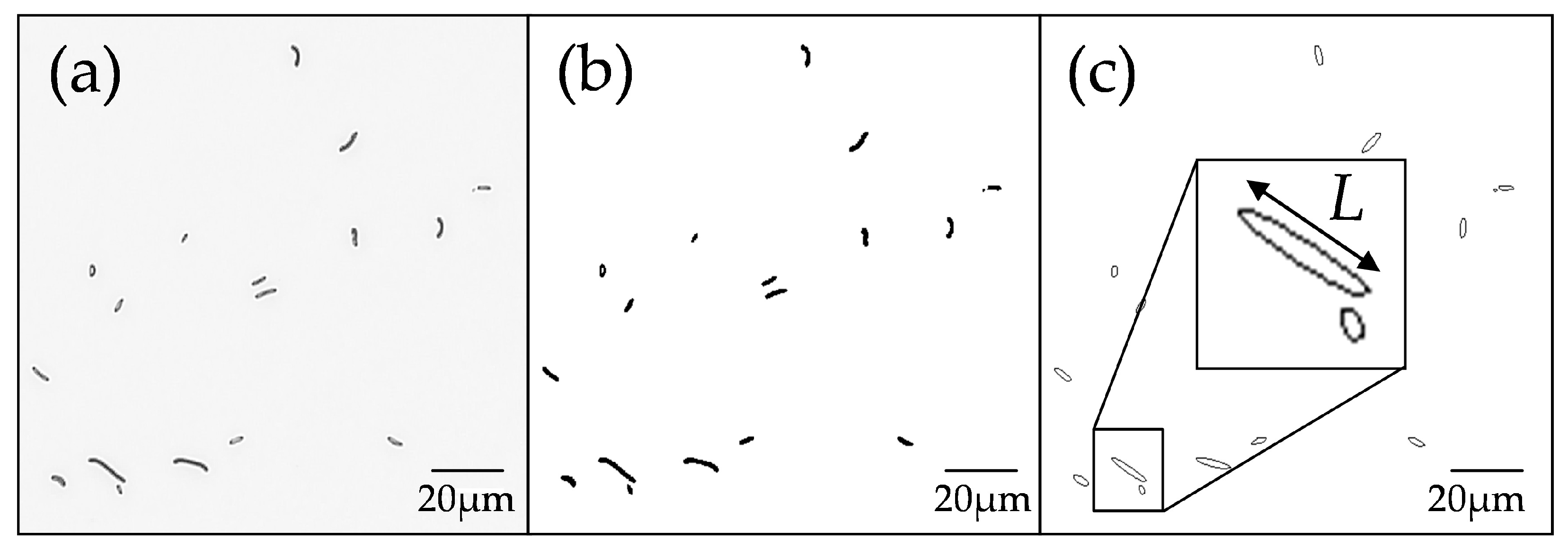
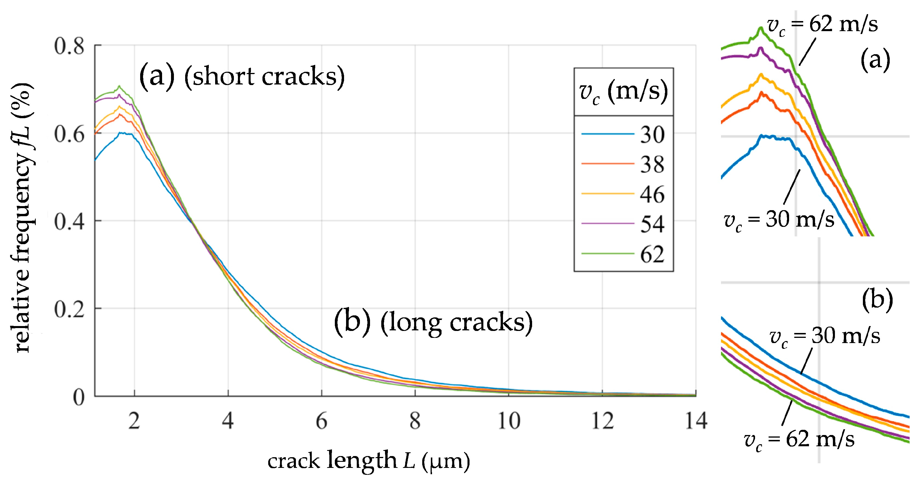
3.3. SSD Analysis by Image Processing
4. Discussion
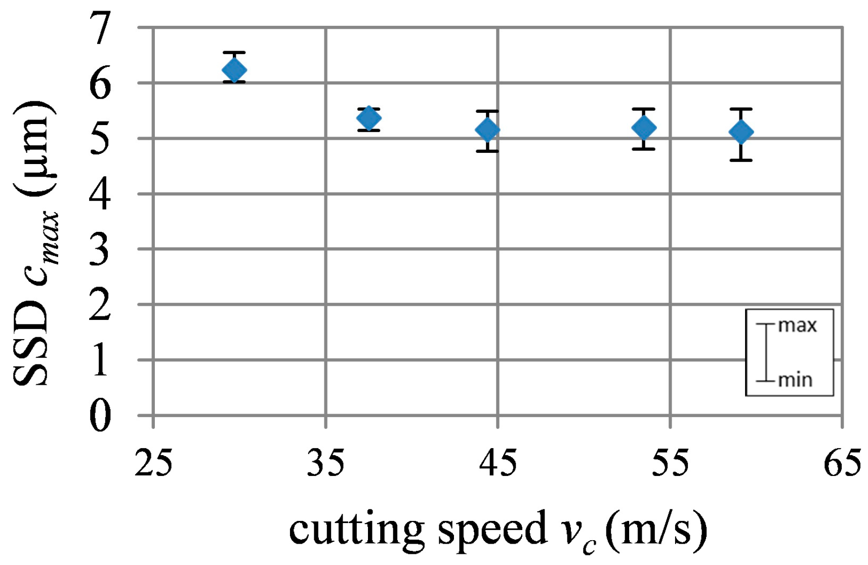
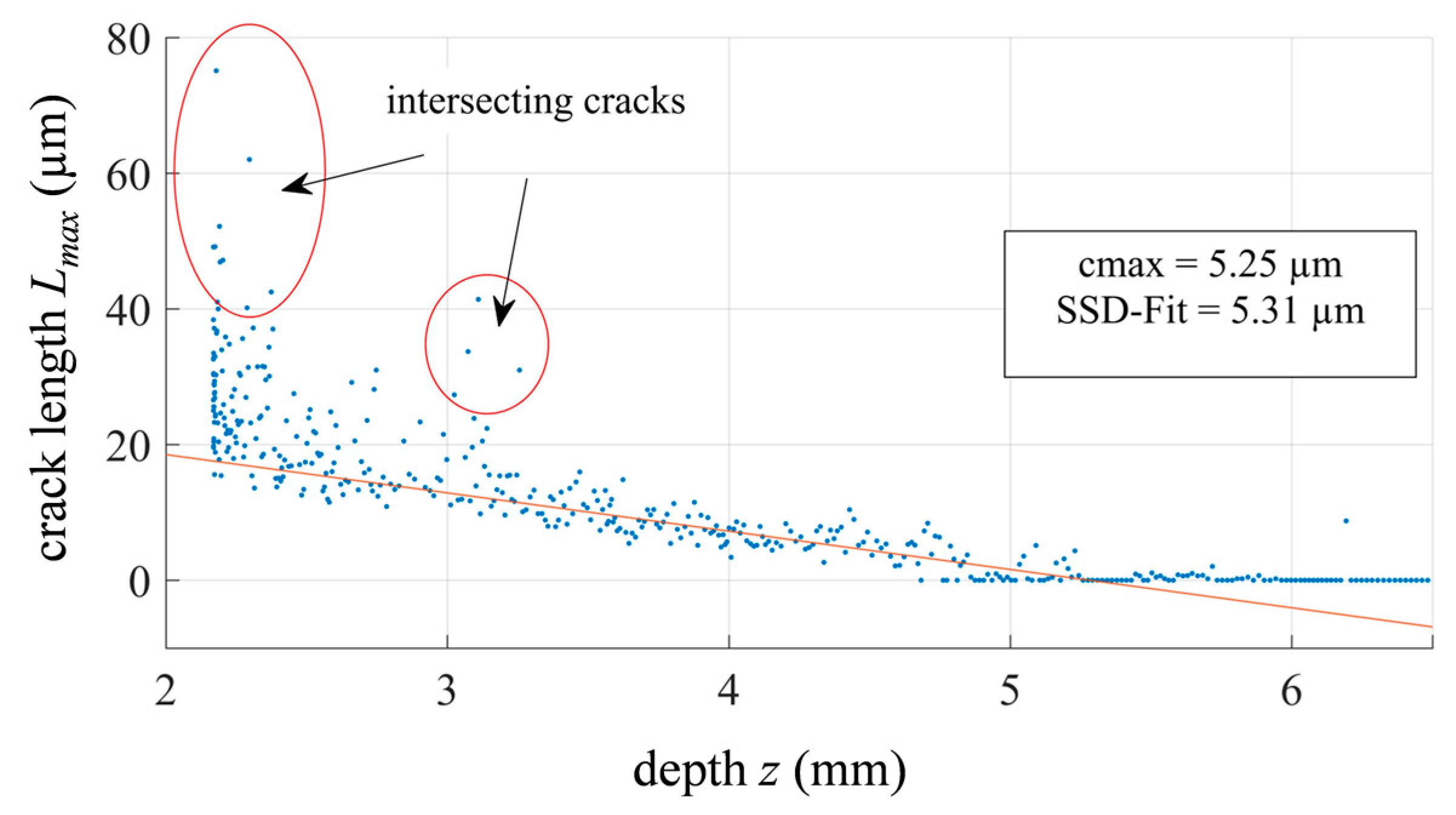
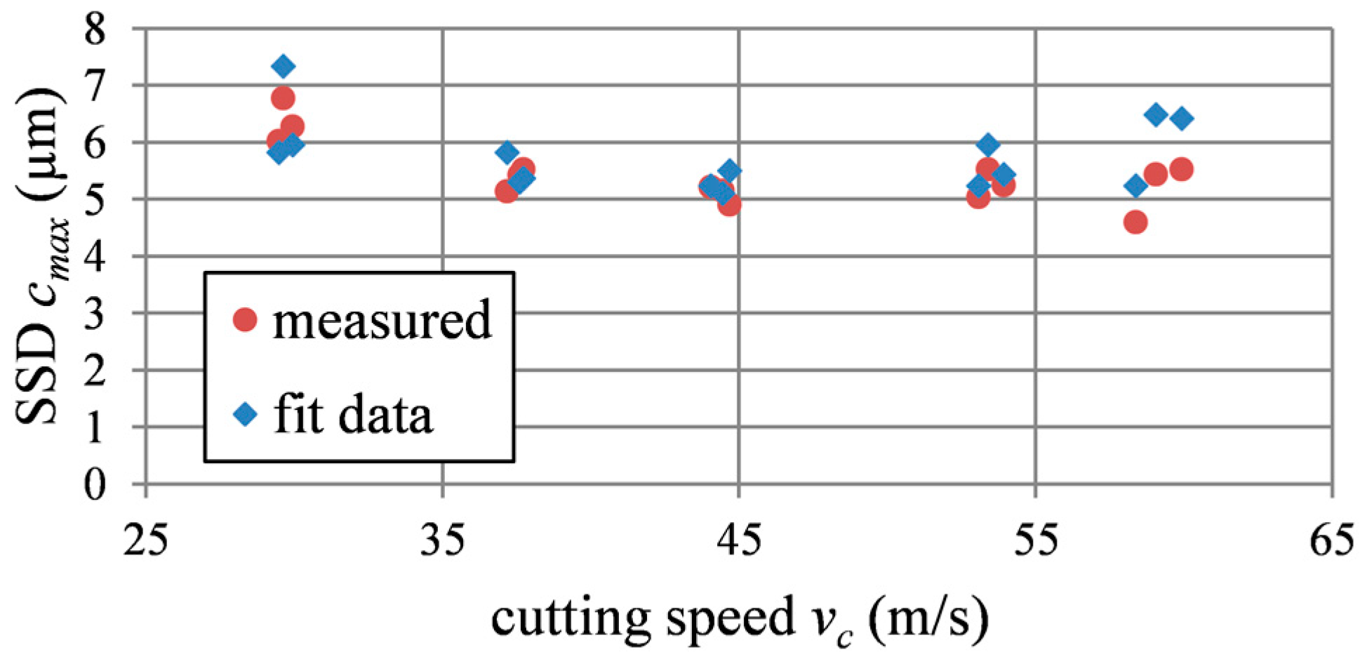
4.1. Maximum Crack Depth
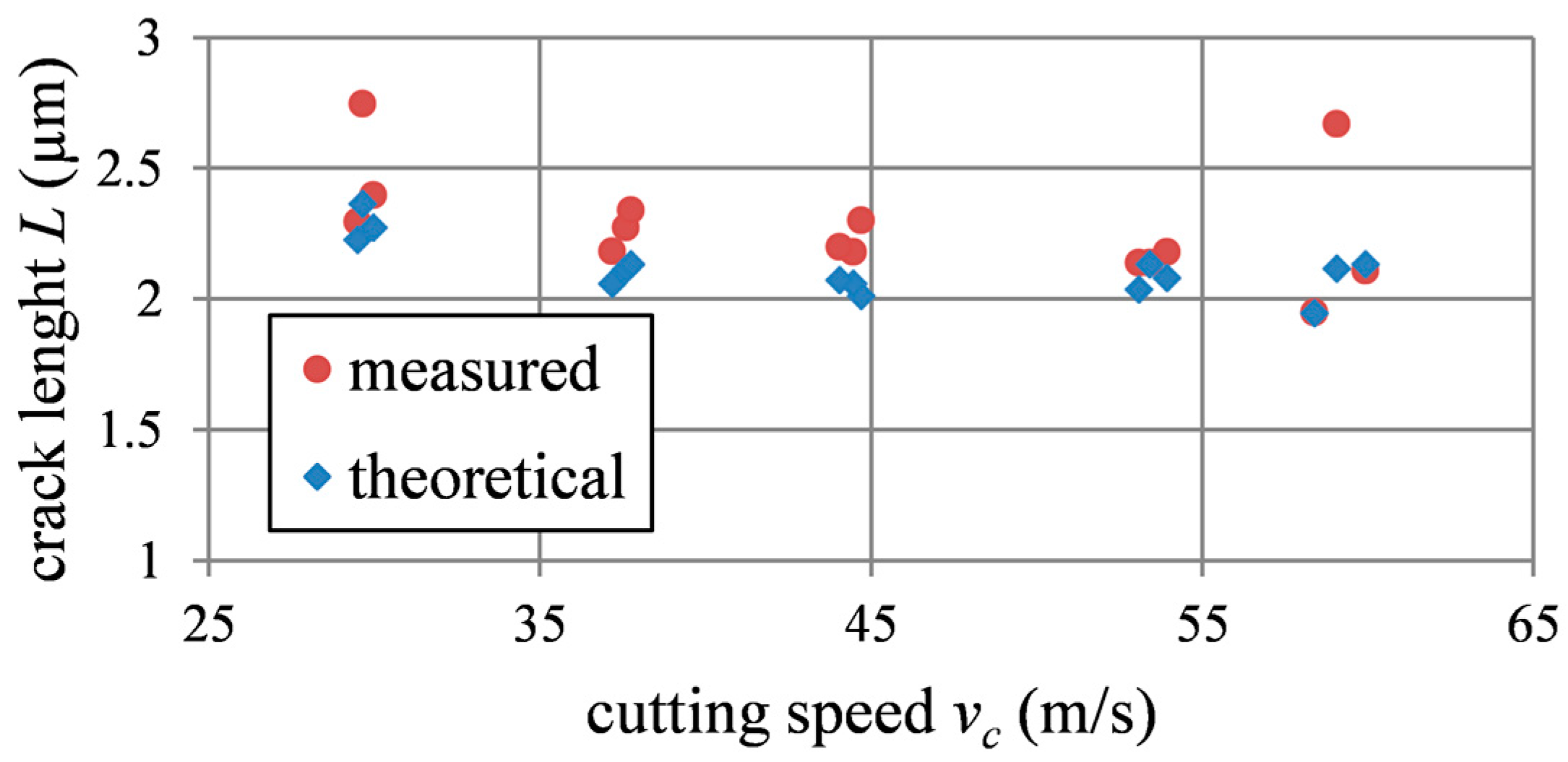
4.2. Fracture Mechanics
5. Conclusions
Author Contributions
Conflicts of Interest
Abbreviations
| a | Hertzian contact circle radius | LMdn | average crack length (median) |
| ae | depth of cut | MRF | magnetorheological finishing |
| cmax | maximum crack depth | ν | Poisson’s ratio (workpiece) |
| cr | radial crack length | ν’ | Poisson’s ratio (indenter) |
| E | Young’s Modulus (workpiece) | nW | worktable speed |
| E’ | Young’s Modulus (indenter) | P | indenter load |
| fL | relative frequency | R | grain size (radius of the abrasive) |
| Fn | normal force | Sa | average surface area roughness |
| H | hardness | SSD | subsurface damage |
| K | mismatch factor | vc | cutting speed |
| KIc | fracture toughness | vfr | radial feed |
| L | crack length | WLI | white light interferometer |
| Lcalc | calculated crack length | χr | indentation constant |
| Lmax | maximum crack length |
References
- Hed, P.P.; Edwards, D.F.; Davis, J.B. Subsurface damage in optical materials: Origin, measurement & removal. In Proceedings of the Optical fabrication and testing workshop, Santa Clara, CA, USA, 2 November 1988. [Google Scholar]
- Neauport, J.; Ambard, C.; Bercegol, H.; Cahuc, O.; Champreux, J.P.; Charles, J.L.; Cormont, P.; Darbois, N.; Darnis, P.; Destribats, J.; et al. Optimizing fused silica polishing processes for 351 nm high power laser application. In Laser-Inducted Damage in Optical Materials, Proceedings of the SPIE, Volume 7132, Boulder, CO, USA, 22 September 2008; Exarhos, G.J., Ristau, D., Eds.; SPIE: Bellingham, WA, USA, 2008. [Google Scholar] [CrossRef]
- Comley, P.; Morantz, P.; Shore, P.; Tonnellier, X. Grinding metre-scale mirror segments for the E-ELT ground based telescope. CIRP Annals-Manufacturing Technology 2011, 60, 379–382. [Google Scholar] [CrossRef]
- Miller, P.E.; Suratwala, T.I.; Wong, L.L.; Feit, M.D.; Menapace, J.A.; Davis, P.J.; Steele, R.A. The distribution of subsurface damage in fused silica. In Laser-Inducted Damage in Optical Materials, Proceedings of SPIE Volume 5991, Boulder, CO, USA, 19 September 2005; Exarhos, G.J., Guenther, A.H., Eds.; SPIE: Bellingham, WA, USA, 2006. [Google Scholar] [CrossRef]
- Lambropoulos, J.C. From Abrasive Size to Subsurface Damage in Grinding. TOPS 2000, 42, 17–18. [Google Scholar] [CrossRef]
- Lucca, D.A.; Brinksmeier, E.; Goch, G. Progress in Assessing Surface and Subsurface Integrity. CIRP Ann. 1998, 47, 669–693. [Google Scholar] [CrossRef]
- Wang, L.; Li, Y.; Han, J.; Xu, Q.; Guo, Y. Evaluating subsurface damage in optical glasses. JEOS:RP 6 2011, 6, 1–16. [Google Scholar] [CrossRef]
- Menapace, J.A.; Davis, P.J.; Steele, W.A.; Wong, L.L.; Suratwala, T.I.; Miller, P.E. MRF Applications: Measurement of process-dependent subsurface damage in optical materials using the MRF wedge technique. In Laser-Inducted Damage in Optical Materials, Proceedings of SPIE Volume 5991, Boulder, CO, USA, 19 September 2005; Exarhos, G.J., Guenther, A.H., Eds.; SPIE: Bellingham, WA, USA, 2006. [Google Scholar] [CrossRef]
- Menapace, J.A.; Davis, P.J.; Steele, W.A.; Wong, L.L.; Suratwala, T.I.; Miller, P.E. Utilization of magnetorheological finishing as a diagnostic tool for investigating the three-dimensional structure of fractures in fused silica. In Laser-Inducted Damage in Optical Materials, Proceedings of SPIE Volume 5991, Boulder, CO, USA, 19 September 2005; Exarhos, G.J., Guenther, A.H., Eds.; SPIE: Bellingham, WA, USA, 2006. [Google Scholar] [CrossRef]
- Randi, J.A.; Lambropoulos, J.C.; Jacobs, S.D. Subsurface damage in some single crystalline optical materials. Appl. Opt. 2005, 44, 2241–2249. [Google Scholar] [CrossRef] [PubMed]
- Li, Y.; Zhenga, N.; Li, H.; Houa, J.; Lei, X.; Chena, X.; Yuana, Z.; Guoa, Z.; Wanga, J.; Guob, Y.; Xua, Q. Morphology and distribution of subsurface damage in optical fused silica parts: Bound-abrasive grinding. Appl. Surf. Sci. 2011, 257, 2066–2073. [Google Scholar] [CrossRef]
- Klocke, F. Manufacturing Processes 2: Grinding, Honing, Lapping; Springer: Heidelberg, Germany, 2009; pp. 251–269. [Google Scholar]
- Wang, H.; Subhash, G.; Chandra, A. Characteristics of single-grit rotating scratch with a conical tool on pure titanium. Wear 2001, 249, 566–581. [Google Scholar] [CrossRef]
- Bollinger, L.D.; Gallatin, G.M.; Samuels, J.; Steinberg, G.; Zarowin, C.B. Rapid, non-contact optical figuring of aspheric surfaces with Plasma Assisted Chemical Etching (PACE). In Advanced Optical Manufacturing and Testing, Proceedings of SPIE 1333, San Diego, CA, USA, 1 July 1990; Sanger, G.M., Reid, P.B., Eds.; SPIE: Bellingham, WA, USA, 1990. [Google Scholar] [CrossRef]
- Suratwala, T.I.; Wong, L.L.; Miller, P.E.; Feit, M.D.; Menapace, J.A.; Steele, R.A.; Davis, P.J.; Walmer, D. Subsurface mechanical damage distributions during grinding of fused silica. J. Non.-Cryst. Solids 2006, 352, 5601–5617. [Google Scholar] [CrossRef]
- Huang, H.; Yin, L. High speed grinding performance and material removal mechanism of silicon nitride. Initiat. Precis. Eng. Begin. Millenn. 2002, 416–420. [Google Scholar] [CrossRef]
- Lawn, B.R.; Swain, M.V. Microfracture beneath point indentations in brittle solids. J. Mater. Sci. 1975, 10, 113–122. [Google Scholar] [CrossRef]
- Lawn, B.R.; Evans, A.G.; Marshall, D.B. Elastic/plastic indentation damage in ceramics: The mediad/radial crack system. J. Am. Ceram. Soc. 1980, 63, 574–581. [Google Scholar] [CrossRef]
- Anstis, G.R.; Chantikul, P.; Lawn, B.R.; Marshall, D.B. A critical evaluation of indentation techniques for measuring fracture toughness: I, direct crack measurements. J. Am. Ceram. Soc. 1981, 64, 533–538. [Google Scholar] [CrossRef]
- Lawn, B.R. Partial cone crack formation in a brittle material loaded with a sliding spherical indenter. Proc. R Soc. Lond. Ser. A 1967, 299, 307–316. [Google Scholar] [CrossRef]
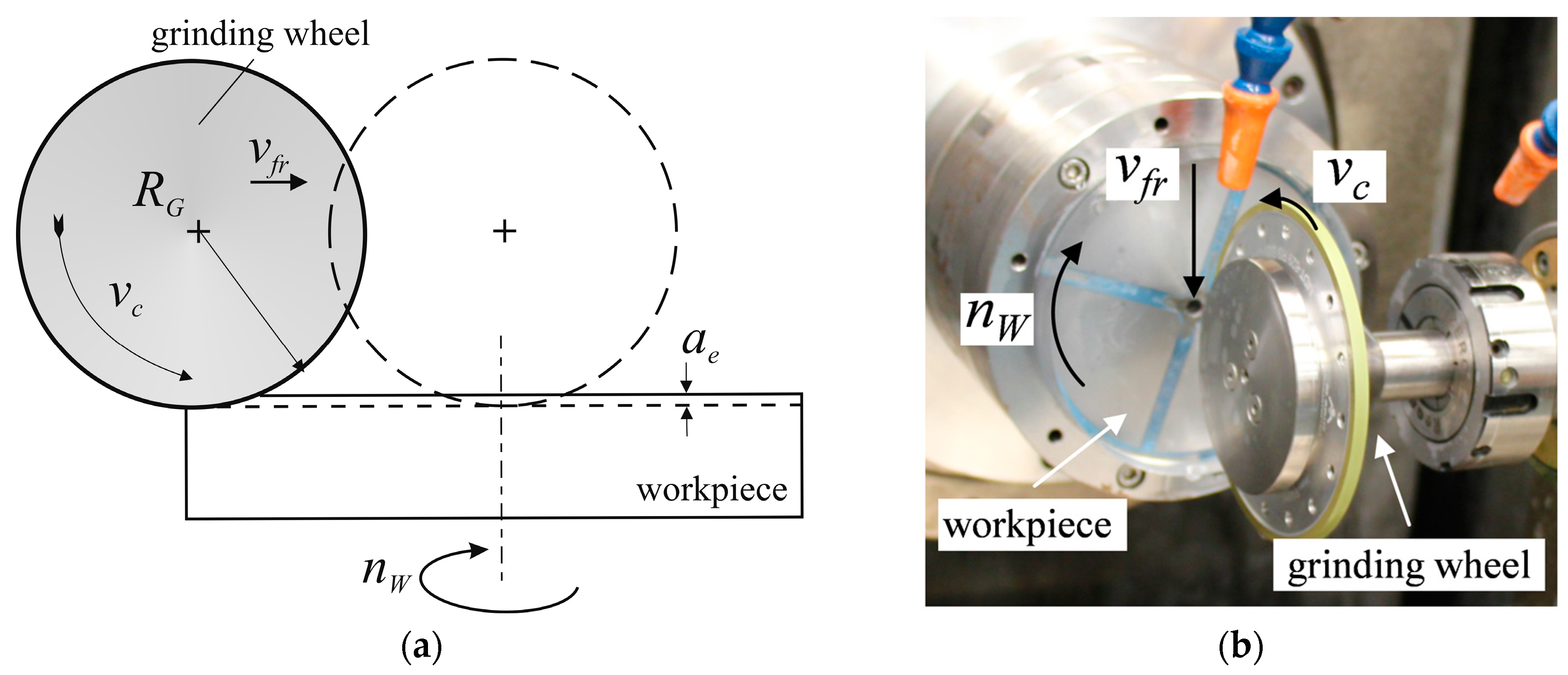

| Process Step | Cutting Speed vc (m/s) | Depth of Cut ae (µm) | Worktable Speed nW (rpm) | Radial Feed vfr (mm/min) |
|---|---|---|---|---|
| 1st step: pre-processing | 30 | 100 (4 × 25) | 50 | 10 |
| 2nd step: SSD experiments | 30–62 | 90 (4 × 20, 1 × 10) | 50 | 10 |
© 2017 by the authors. Licensee MDPI, Basel, Switzerland. This article is an open access article distributed under the terms and conditions of the Creative Commons Attribution (CC BY) license (http://creativecommons.org/licenses/by/4.0/).
Share and Cite
Schnurbusch, G.; Brinksmeier, E.; Riemer, O. Influence of Cutting Speed on Subsurface Damage Morphology and Distribution in Ground Fused Silica. Inventions 2017, 2, 15. https://doi.org/10.3390/inventions2030015
Schnurbusch G, Brinksmeier E, Riemer O. Influence of Cutting Speed on Subsurface Damage Morphology and Distribution in Ground Fused Silica. Inventions. 2017; 2(3):15. https://doi.org/10.3390/inventions2030015
Chicago/Turabian StyleSchnurbusch, Georg, Ekkard Brinksmeier, and Oltmann Riemer. 2017. "Influence of Cutting Speed on Subsurface Damage Morphology and Distribution in Ground Fused Silica" Inventions 2, no. 3: 15. https://doi.org/10.3390/inventions2030015
APA StyleSchnurbusch, G., Brinksmeier, E., & Riemer, O. (2017). Influence of Cutting Speed on Subsurface Damage Morphology and Distribution in Ground Fused Silica. Inventions, 2(3), 15. https://doi.org/10.3390/inventions2030015


