1. Introduction
Effective thermal management of electronic equipment is pivotal to maintain silicon junction temperatures below critical threshold temperatures. For the past few decades, the advent of IC (integrated circuit) chip follows the well-known Moore’s law which doubles the number of transistors in a dense IC approximately every two years. Moreover, the IC chip not only shrinks in size but also boosts its power consumption and yields considerable amount of waste heat that must be managed. With shrinkage in size and larger heat dissipation simultaneously, yet the required temperature difference for thermal management is also reduced due to complexity of IC hierarchy, making it even tougher for effective thermal management. In practice, the most popular cooling method takes the form of air-cooling. However, air-cooling suffers from low heat transfer performance and noise problems. To tailor this difficult situation, alternatives like heat pipes, liquid immersion, jet impingement and sprays, thermoelectrics, loop heat pipe, vapor chamber, nucleate boiling, refrigeration, and other possible heat spreading devices such as micro-channel heat exchangers with single phase or two-phase design are also considered [
1,
2]. However, due to the concerns of cost, simplicity, and reliability, air cooling still outnumbered other thermal management solutions. As a result, various air-cooled thermal modules are manufactured and supplied to the markets in mass quantity.
In general PC (personal computer) cooling, cooling the CPU (central processing unit) chip is the primary task. A vast research concerning the heat sink design and fin profile for cost and performance optimization had been made in the literatures. Some typical deigns in association with fin patterns were proposed, e.g., [
3,
4,
5,
6]. With the advent of mobile devices, servers in datacenter take over the major task work from PC. Nowadays major data processing and computing are mainly performed in the datacenters. In fact, datacenters are becoming the heart of data storage, processing, transactions, and computing. To maintain the operational temperatures below required threshold values for the servers inevitably boost the electricity consumptions of datacenter considerably. Hence, cooling of server within computer rack becomes an important issue for thermal solution providers. In practice, thermal management of servers not only ask for thermal performance; but also requires a lower flow impedance (pressure drop) whenever possible. With regard to easier manufacturing, the plate fin heat sink as schematically shown in
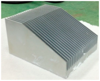
Figure 1 is still the most widely adopted fin design. Due to the limited space in motherboard for effective heat removal, the heat sink is usually designed with small fin spacing to accommodate more fins that could lead to unaffordable pressure drop penalty. Standard 1U/2U server systems not only have CPU chips, but they are also densely packed with other chips for different functions to process gigantic amount of data. Unlike PCs, in order to save precious room space in datacenter, these systems are rack-mounted one by one. The design concept of server system is to design heat sink with proper thermal performance subject to the least flow impedance to entrain more airflow for cooling these chips behind CPUs. Normally, as shown in
Figure 1, cross airflow arrangement rather than impingement is normally adopted in applications to meet the space confinement. The accurate volumetric airflow through heat sink is a function of flow impedance which can be described via the P-Q curve of the prescribed fans. Hence, accurate estimation of flow rate in association with fans is very important. This also raises an important issue to lower the flow impedance (pressure drop) of heat sink; since more airflow is able to pass across heat sink with prescribed fans. In the subsequent overview, some recent ingenious designs to lower flow impedance will be addressed in more details. In the meantime, heat sinks with smaller fin spacing may bring about fully developed flow that significantly deteriorates the heat transfer characteristics, yet the comparatively short length of heat sink also implies a considerable portion of heat sinks may be operated in the developing flow region. In searching of the ultima performance improvements of air-cooling heat sinks, the foregoing results indicate that different augmentation methodology may be incorporated into typical heat sinks in order to maximize the overall performance.
The present overview summarizes the recent developments of heat sink design applicable to forced convective applications under cross flow arrangement. Efforts are stressed on heat transfer augmentation, pressure drop reduction, material saving, and some possible augmentations for the future study. There had been numerous studies concerning the optimization, correlations or parametric influences on the performance of convectional heat sink having plate or pin fin configurations, e.g., [
7,
8,
9,
10,
11,
12,
13,
14,
15]. However, it is not the purpose of this review to sum up all these kind of contributions. Instead, the effort and objective is to explore and summarize some new concepts of augmentations for air-cooling heat sinks subject to cross-flow conditions.
2. Problems of Heat Sink for Housing More Fin Surfaces
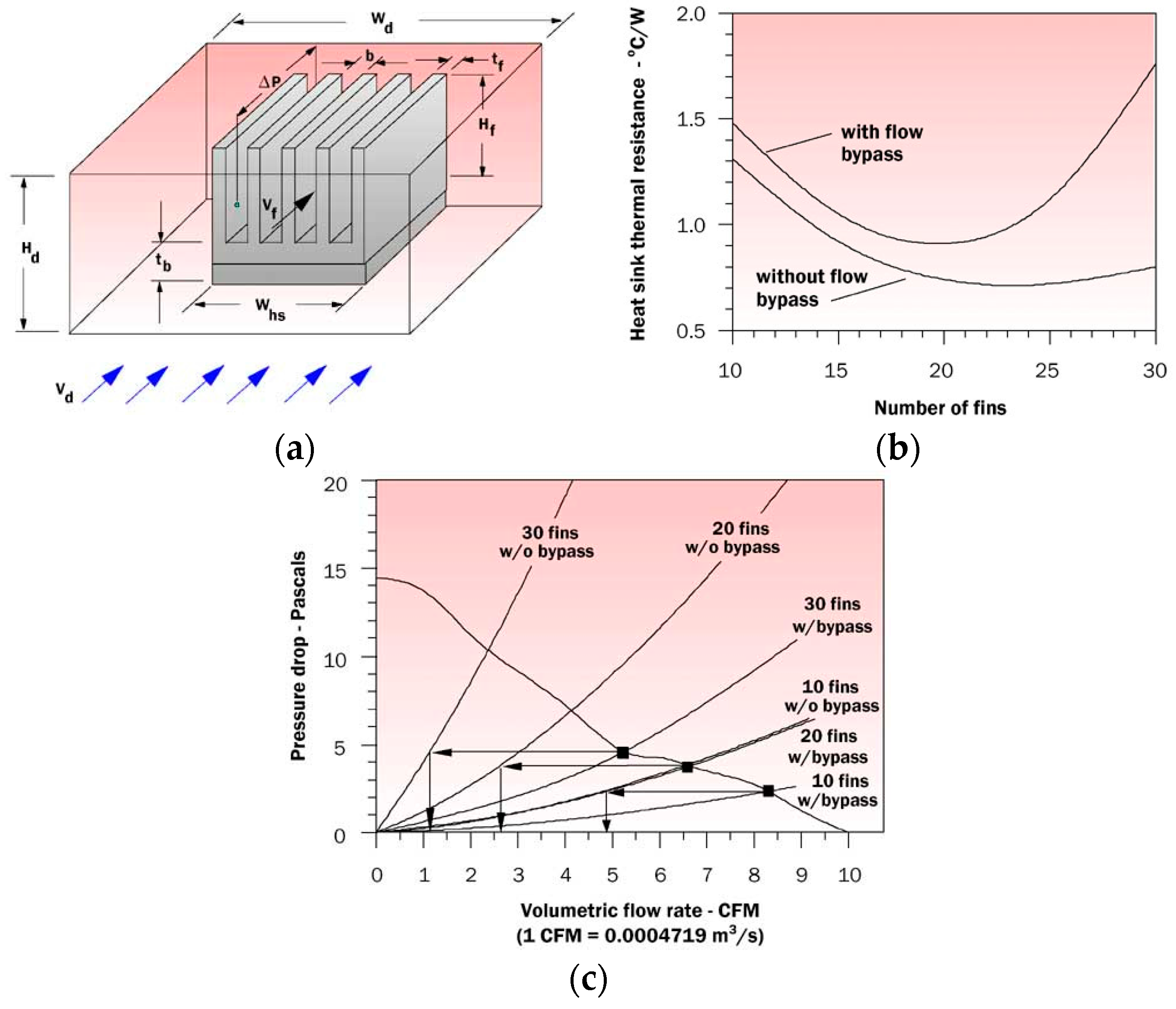
The considerable low thermal conductivity of air (k ~0.26 W/m·K) inevitably results in a very low heat transfer coefficient as compared to that of water (k ~0.6 W/m·K). Hence designers are always eager to search an ultimate heat sink that can dissipate heat generation efficiently when direct air cooling is employed. The easiest way is to introduce more fin surface. At first sight, it seems feasible but the heat transfer performance may suffer appreciably due to higher frictional resistance and flow mal-distribution problem. This can be illustrated from the test results of Simon [
16] who examined the effect of flow bypass on an aluminum heat sink having a heat sink profile of 50 mm wide × 50 mm long with 0.5 mm thick 25 mm tall fins as depicted in
Figure 2a. He also examined the effect of flow bypass. For operation without bypass, the thermal resistance decreases initially with the rise of fin number (smaller fin spacing). Yet a marginal rise of thermal resistance is encountered when the fin number surpassed 22 as shown in
Figure 2b, indicating adding more fins is simply futile. Yet this phenomenon becomes even more pronounced with heat sink being operated subject to flow bypass, suggesting accommodation more fin surfaces above certain threshold may impose negative effect on the thermal characteristics. The reversed effect of adding fin surfaces can be explained from the fan curve of
Figure 2c. A low flowrate prevails for a accompanied fan due to larger friction. Consequently, the decreased flowrate may surpass the positive effect of adding surface area and offset the thermal resistance accordingly. In addition, adding more fin surfaces is also susceptible to a higher cost and gaining more weight. In summary of the foregoing discussion, heat sink with more fin surfaces may not be a good way to improve the overall performance.
There were also some other ways to house more surfaces into a heat sink such as employing porous structure into the heat sinks to lower the thermal resistance. For example, Xu and Wirtz [
17] and Li and Wirtz [
18] proposed a novel high-performance heat sink based on screen-fin technology. As shown by Xu and Wirtz [
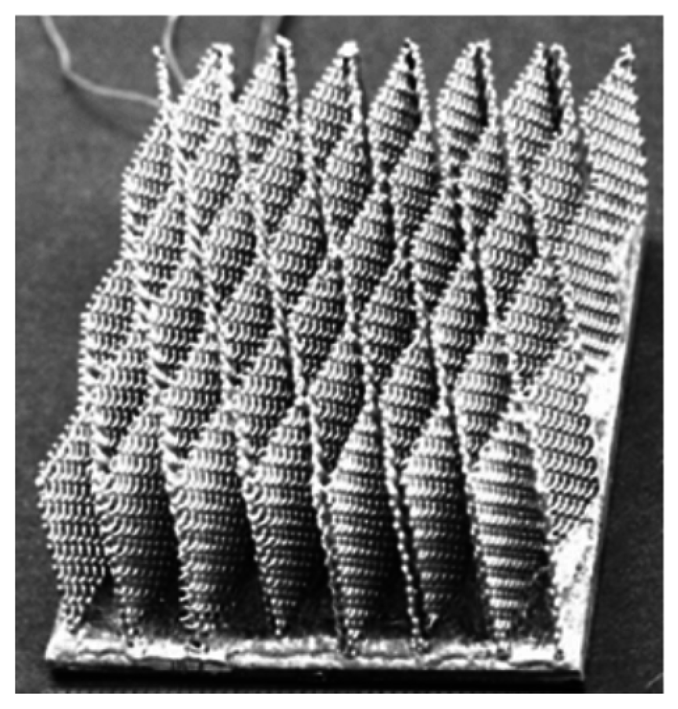
17], the plain-weave screen laminates can be fabricated into simple porous media structures to achieve an approximate 19% of in-plane effective thermal conductivities relative to base material and for isotropic weaves to attain 78.5% of base material values for anisotropic weaves. The schematic of the prototype is shown in
Figure 3. Test results by Li and Wirtz [
18] also indicated that the effective conductance for the screen laminate is comparable to that of plate fin when the frontal velocity is less than 3.3 m/s. However, the performance is inferior to plate fin geometry when the frontal velocity is increased further. This is somewhat expected due to significant drop of fin efficiency of the porous structure and the decline becomes more pronounced at high speed regime.
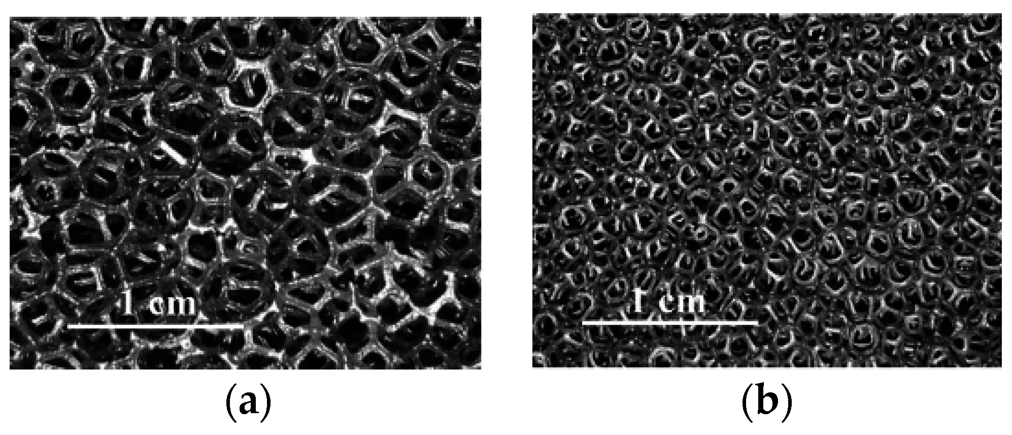
Another way to house more surfaces into a heat sink is via a metal foam porous structure as shown in
Figure 4 [
19]. The metal foam is a cellular structure having a solid metal with gas-filled pores. The pores can be sealed (closed-cell foam) or interconnected (open-cell foam), and open-cell foam is considered in electronic cooling applications. The main features of metal foams include light weight and high porosity. Normally only 5%–25% of the volume is occupied by the base metal, thereby encompassing a huge surface area within a confined volume with a much lighter mass. Open cell metallic contains many outstanding features such as higher surface area per unit volume, good structural strength, and excellent flow mixing capabilities, making them good candidates for compact heat exchangers and heat sinks [
20]. The major concerns for adopting this technology into heat sink market include significant rise of pressure drop, lower fin efficiency, clogging of dust after long term operation, and much higher cost. The last concern, with a much higher cost, often limits the applicability of using metal foam in practice, especially for those air-cooled heat sinks. As far as performance is concerned, employing metal foam in liquid cooling heat sink shows a substantial improvement relative to the conventional heat sinks. For example, Boomsma et al. [
21] showed that the thermal resistances of the open-cell aluminum foam heat exchangers were two to three times lower than the commercially available heat exchanger tested at the same pumping power. Their working fluid is a 50% water–ethylene glycol solution. Similar results were reported by Chen and Wang [
22]. However, converse to the liquid cooling application, the air and high volumetric airflow requirement often implies a much larger fin height may lead to very lower fin efficiency, suggesting metal foam with long fin height dimension may be ineffective. This can be made clear from the test results of Aly et al. [
23] who conducted experiments with aluminum metal foams having 93% porosity with the pore density being 4 and 8 PPI (i.e., pores per inch) subject to air-cooling. For a frontal velocity of 3.6 m/s, their measurement indicated that the efficiency of the solid fin is about 82.7% while the metal foam is only 39.7%. In this regard their results showed only moderate reduction in thermal resistance by using metal foam as compared to solid heat sink. Yet in some cases of their tests the solid fin heat sink may even outperform the metal foam. To remedy the inherited problem of low fin efficiency, Krishnan et al. [
24] adopted a 3-D printing plastic patterns and converting them into monolithic copper structures by investment casting. They had tested four fin patterns, including parallel plate, slotted hexagon, fin-foam, and Schwartz structure. The fin foam, as shown in
Figure 5a, characterizes combination of solid plate fin with copper foam forming between fins. The design improves the low efficiency associated with metal foam to some extent. The slotted hexagon features honeycomb type structure as schematically shown in
Figure 5b. The Schwartz type structure uses the concept of excitation of shear-layer (laminar) instabilities for heat transfer augmentation based on minimal surfaces, and its configuration is shown in
Figure 5c. Their test results in terms of thermal resistance vs. frontal velocity and pumping power are shown in
Figure 6. From the test results, it is not surprising that the fin-foam possess the lowest thermal resistance at a fixed pumping power. This is associated with the improvement of effective fin efficiency with the presence of solid fin. In contrast, the Schwartz structure Schwartz type structure which make uses the concept of excitation of shear-layer (laminar) instabilities shows the worst performance overall. This, can be explained from the nature of this structure which contains periodic contraction and expansion of the airflow across the fin passage. From the monograph of Kays and London [
25], the contraction loss is comparatively large in laminar flow, and the periodic structure definitely worsens the pressure loss and lead to a drop of thermal performance.
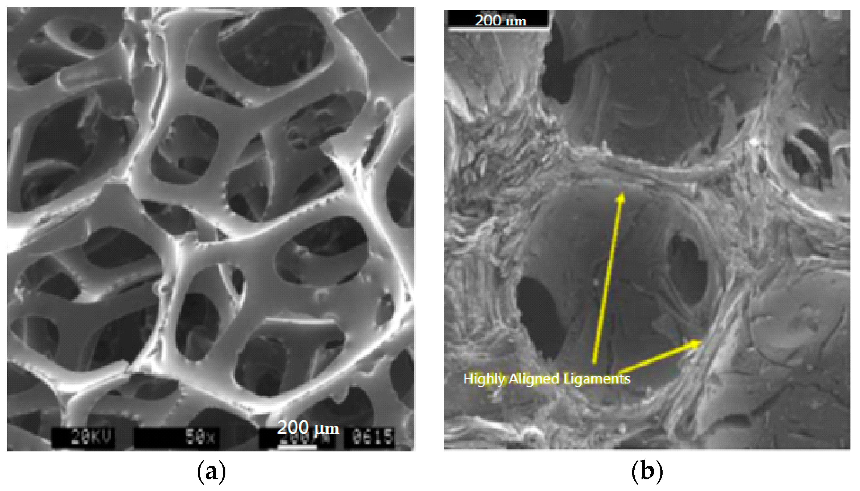
In addition to the metal foam, carbon foam can also house sufficiently amount of surfaces as well. The high-conductivity graphitic foam developed at Oak Ridge National Laboratory (ORNL) [
26] shown in
Figure 7a is an open-cell structure with highly aligned graphitic ligaments. Studies had shown that the typical interlayer spacing is 0.34 nm which is very close to perfect graphite. Thermal conductivities along the ligament were calculated to be approximately 1700 W/m·K [
27], suggesting it can significantly improve the loss of fin efficiency as compared to typical metal foam. For more details about the carbon foam, interested readers are resorted to the review article by Wang et al. [
28] who had made a thorough review concerning the potential in thermal management of carbon foam. Currently, the major limitation of the carbon foam is difficult to shape and to join them and the cost may be too high to afford in electronic cooling applications.
3. Heat Transfer Augmentation via Fin Configuration
From the fundamental Newton’s cooling law, the heat transfer rate is given by
where
Q is the heat transfer rate,
h is the heat transfer coefficient,
A surface area, η
o surface efficiency, and Δ
T is the mean temperature difference. Thus, heat transfer enhancement is primarily by increasing surface area, heat transfer coefficient or Δ
T. Enhancement upon heat transfer coefficient through fin geometry can be made available through mechanisms such as boundary layer restarting or swirled flow. To enhance the performance of air-cooled heat sink, Yang et al. [
29] proposed some highly interrupted fin surfaces in forms of louver or slit fin for their compact heat sink as shown in
Figure 8. Apparently through the help of highly interrupted surfaces, the renewal of boundary layer augments the heat transfer performance appreciably. However, they found that the enhancements are effective only when the fin spacing is above 1.6 mm. In the meantime, severe pressure drop penalty accompanies with the interrupted surfaces. Moreover, for a smaller fin spacing like 0.8 mm, significant drop of heat transfer performance is observed especially when the low Reynolds number drops below 600. The significant decline in heat transfer performance is due to the presence of fully developed flow. The original concept of heat transfer enhancement via interrupted surface is with periodical renewal of boundary layer. Unfortunately, some researchers like Yang et al. [
29] and Webb and Trauger [
30] had pointed out that typical interrupted surfaces such as louver fin reveals detectable heat transfer degradation in the low velocity region. This is because the airflow may not be directed through the louver fin but mainly flows alongside the channel (so called “duct flow” phenomenon). Some similar results concerning the performance drop for the louver fin geometry in the low velocity region had been reported by Davenport [
31] and Achaichia and Cowell [
32]. The flow visualization experiment carried out by Webb and Trauger [
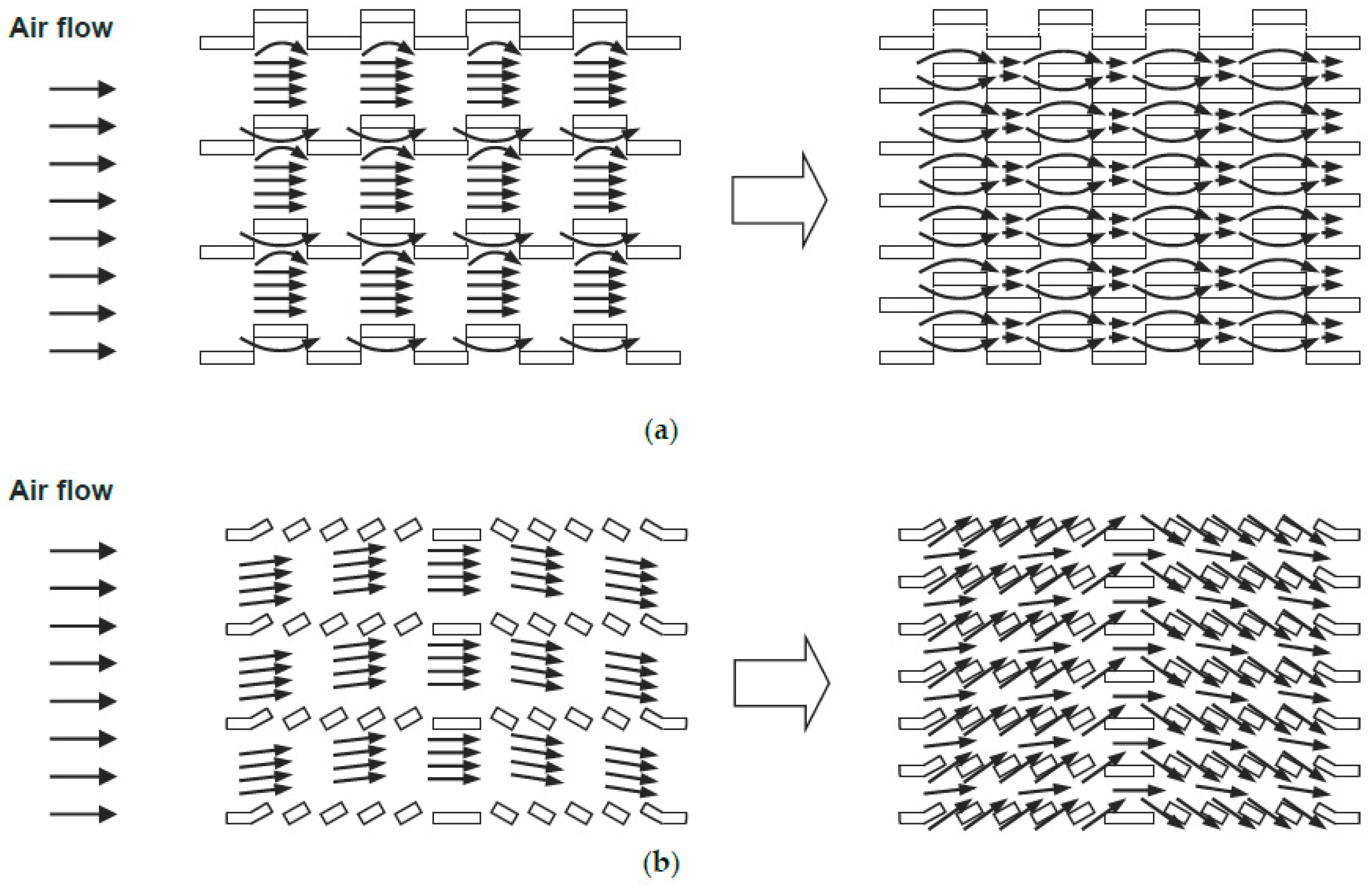
30] also confirmed the phenomenon that some of the air streams bypass the louvers, representing the so-called “duct flow” between the fin channels, and lower its heat transfer coefficient accordingly. A schematic of the airflow pattern in association with fin direct flow and duct flow is shown in
Figure 9. Though the low velocity operation in automotive heat exchanger may not be so common, however, low velocity operation with dense fin spacing is often encountered in many electronic cooling applications since space constraint and noise concerns need to be resolved in practice.
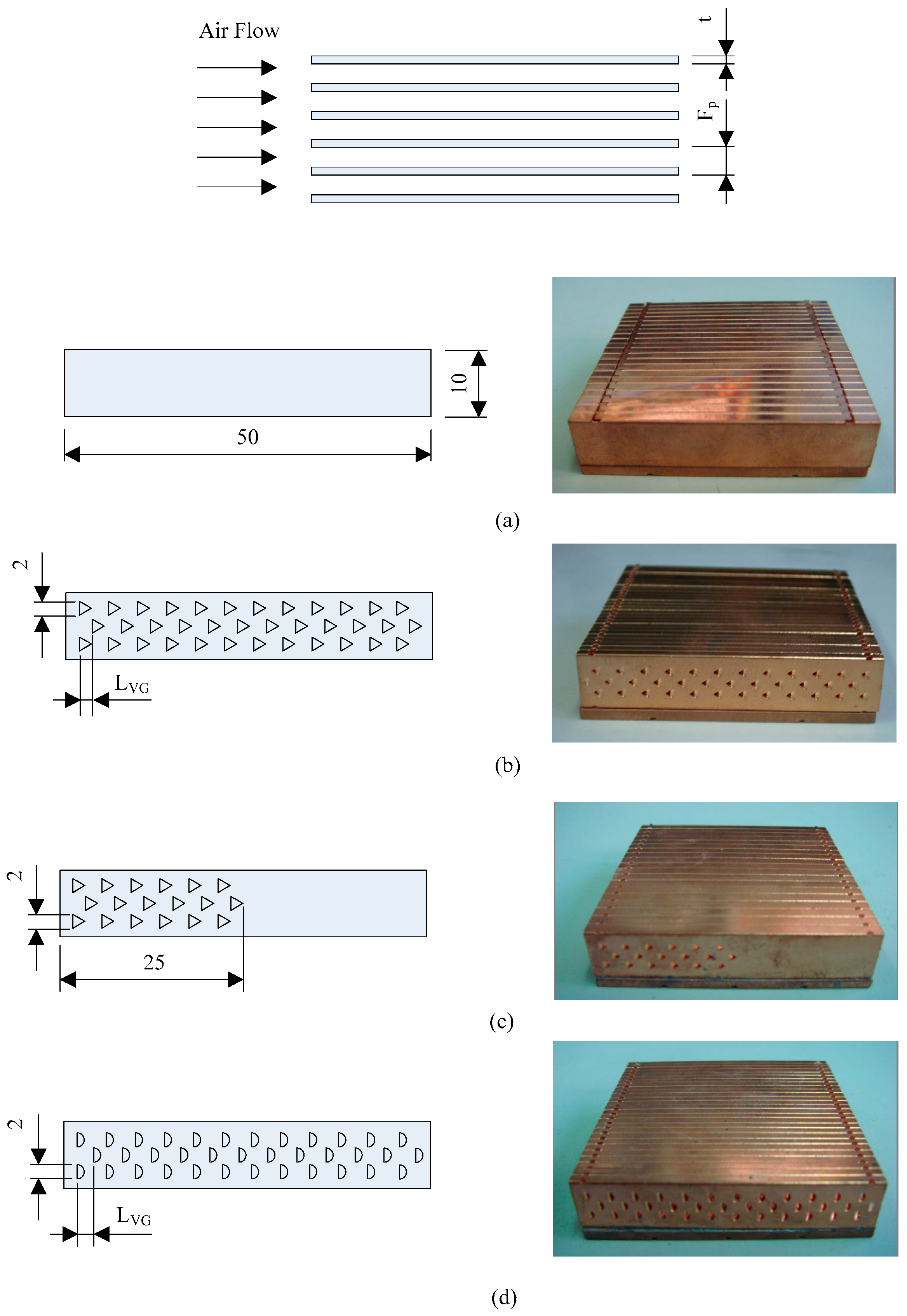
In addition to the forgoing interrupted surface, the fin surface can be designated as swirled flow devices which make use the longitudinal vortex generator (LVG). As pointed out by Jacobi and Shah [
33], the air-side temperature distribution is closely related to the velocity field and the temperature distribution through which affects the air-side heat transfer resistance appreciably. In practice, flow manipulation is either via alterations of the main flow or exploitation of the secondary flows. The LVG is a secondary flow augmentation that can provide certain heat transfer augmentation without significant pressure drop penalty. In fact, a recent study by Wang et al. [
34] had mentioned that the semi-dimple LVG can be more effective than the louver fin geometry for fin-and-tube heat exchanger with fewer number of tube row. For electronic cooling using LVG, Yang et al. [
35,
36] had experimentally examined various types of vortex generator, such as delta wing, triangular winglet, semi-circular, and dimples having loose and dense density. The LVG tested by Yang et al. [
35] is depicted in
Figure 10 and the fin pattern, fin pitch, fin numbers and LVG pitch, and opening angle is tabulated in
Table 1. All the samples have the same fin thickness of 0.08 mm. Their test results indicated that the heat sinks with semi-circular LVGs show the highest pressure drop than other fin types. Yet the pressure drop of dense delta LVGs is higher than that of loose delta LVGs and that of LVGs + plain fin. Converse to the pressure drop, the heat transfer coefficients regarding various fin configurations depend on the fin pitch. With a larger fin pitch like 1.85 mm or 2.63 mm, plain fin always shows the lowest heat transfer coefficient. At a rather dense fin pitch of 1.0 mm, the plain fin outperforms most of the enhanced fin patterns like semi-circular, LVG (loose), and LVG (dense) and is second to LVG + plain. This phenomenon becomes even more evident when the frontal velocity is low. Their test results indicated that fewer LVGs often outperform those with more LVGs as far as pressure drop is concerned. In addition, as expected, the resultant pressure drop of LVG is much lower than those interrupted surfaces. Unlike those of interrupted surfaces, the LVGs are comparatively effective in the developing region. Yet they become less effective in the fully developed region. In addition, like interrupted surface, employing LVGs are less effective when the fin spacing is small or operated at a lower frontal velocity. This is because the formation of swirled flow may be limited in confined spacing. In summary of their studies, it appeared that LVGs are less effective at low velocity region or small fin spacing while the plain fin is still superior to most other fin patterns in the fully developed region. Moreover, interrupted surfaces or LVGs still suffer from the constriction of conduction due to some removal of surface alongside the fin. Test results for the delta winglet LVG by Chomdee and Kiatsiriroat [
37] also showed only moderate increase in heat transfer performance.
To remedy the ineffectiveness of typical interrupted surface and swirled flow configuration for very dense heat sink under low velocity operation, Wang et al. [
38] suggested a novel cannelure fin structure and eight heat sinks were made and tested. The fin geometries include plain fin; oblique dimple; variations of cannelure; and combinations of dimple/cavity as depicted in
Table 2. Note that the basic concept of the novelty lies in the shrinkage (or cavity like) enhancement design rather the typical intruding surfaces as shown in
Table 2. The fin spacing of the test heat sinks are all 0.8 mm. The idea is to mimic golf surface that helps to reduce friction and improve the heat transfer moderately. Analogous idea with appreciable heat transfer improvement but with marginally reduction in friction had been reported by Afans’yev et al. [
39]. Their study depicted a 30% increase of heat transfer performance at a cost of negligible pressure drop penalty when the air flows over a pit/groove along a smooth wall. However, the idea is not suitable to be implemented in electronic cooling with fully distributed cavities. This is because the fin thickness is usually thin and creating cavity in one side will cause dimple on the other side. Test results by Yang et al. [
35,
36] had confirmed that using full cavity/dimple design alongside the surface (e.g., Yang et al. [
35,
36]) is simply futile. Hence, use fewer combinations of dimple/cavity will suffice when employs the shrinkage enhancement structure. In summary, combination of the cannelure fin configuration along with the dimple/cavity structure by Wang et al. [
38] showed an approximately 25% rise in heat transfer coefficient while the corresponding pressure is reduced by about 20%.
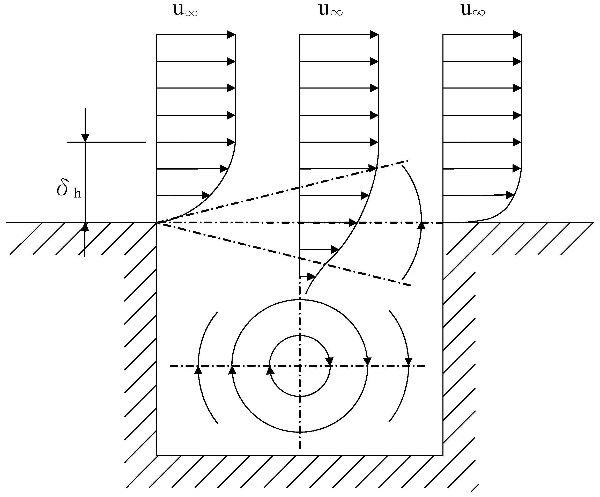
Moreover, different from those interrupted fin or LVGs, the cannelure fin structure still reveals significant enhancement of heat transfer performance in fully developed region. The appreciable increase of heat transfer without the pressure drop penalty is due to the local suction/blowing flow and the near wall vortical motion resulted from the cannelure structure. The results were further substantiated by their observed IR image. For a further elaboration of this phenomenon, one can see a schematic illustrated in
Figure 11. When the airflow approaches the cannelure structure, the velocity profile is strengthened in association with no slip condition at the bottom of the cannelure structure, thereby emerging a vortical motion. As air flows towards the end of cannelure structure, two separate streams are generated and the stream above the cannelure shows a higher velocity profile near the surface when compared to fully developed region ahead of the cannelure. Yet the stream below the cannelure structure flows toward cannelure and rises up to become an upwash stream that is actually very similar to the cavity structure [
40]. The upwash flow and the flow distribution passing the cannelure to form a near wall swirled motion, resulting in a rise in heat transfer. In essence, the resultant near wall vortical structure is analogous to typical suction/blowing flow. As a consequence, appreciable heat transfer enhancement is attained without the penalty of pressure drop (Kasagi et al. [
41]). Notice the extensively numerical study upon local suction/blowing phenomenon by Kasagi et al. [
41] had clearly identified the control of this near wall structure can considerably increase the heat transfer performance while still kept the induced pressure drop penalty to be hardly noticeable or just very slightly. Choi et al. [
42] had developed a so-called opposition control based on the knowledge of near-wall coherent turbulent structures. In essence, despite the cannelure shows promising features, the design can only provide moderate improvements in heat transfer.
An analogous design using the V-shape cannelure structure is also implemented for the thermal module for cooling of projectors by Huang and Wang [
43]. Their simulation and the actual sample are shown in
Figure 12. Their simulation revealed when the air flow passed across the heat pipe, the V-shape geometry can direct the airflow through the cannleure structure, leading to a rise of heat transfer coefficient alongside the structure. As a result, it shows a superior heat transfer performance as compared to the plate or vertical cannelure structures. The authors also implemented the heat pipe module as seen in
Figure 12b. The sample features a 30% less in volume (and surface) than the original plate fin heat sink module while still possesses a lower junction temperature than the original one by 1 to 3 °C provided that a frontal velocity is above 1.5 m/s.
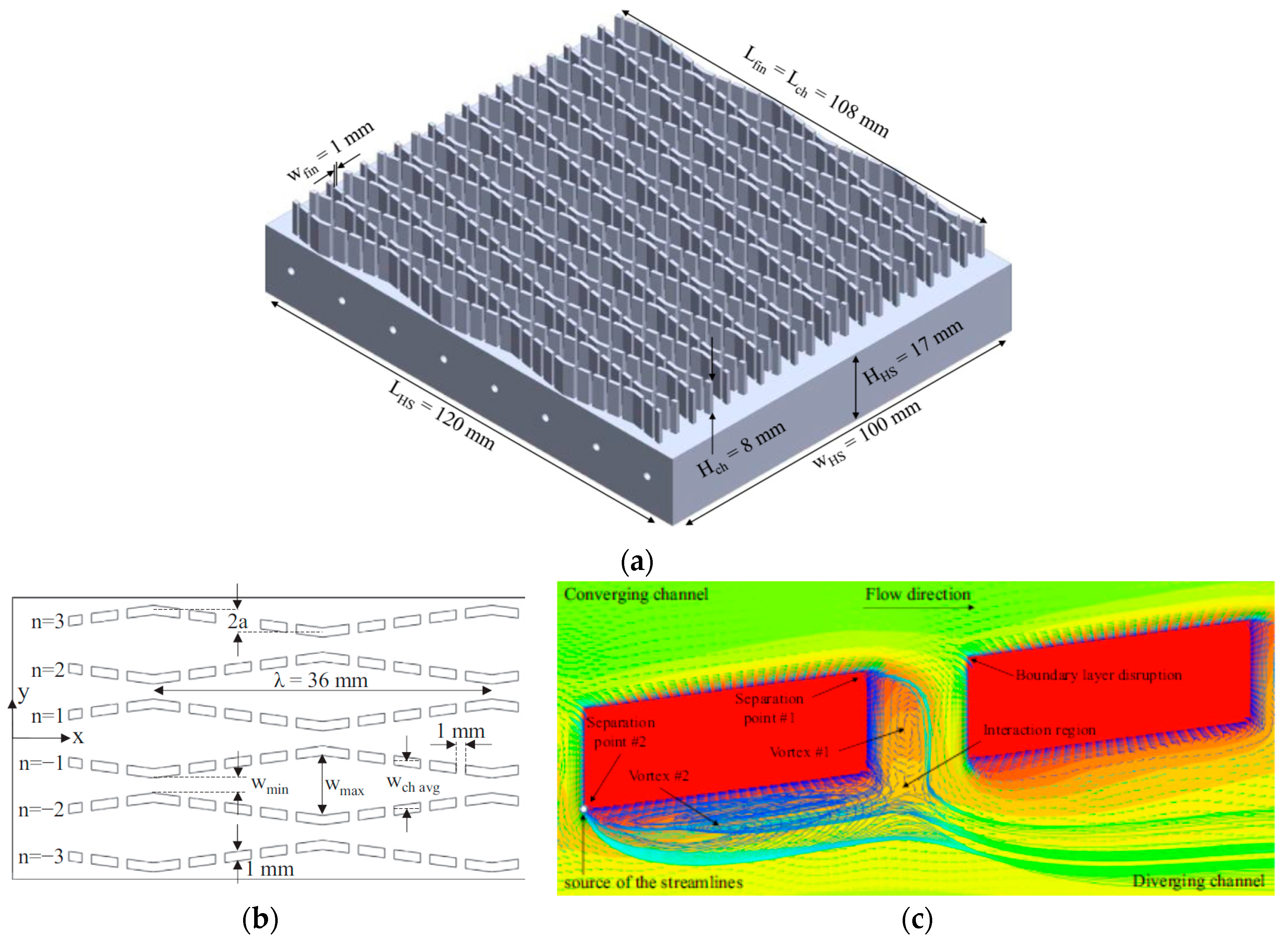
As shown in
Figure 13a, Kanargi et al. [
44] recently proposed a cross-connected alternating converging–diverging heat sink, and the detailed dimension can be seen from
Figure 13b. They had conducted both numerical and experimental investigation of this structure in comparison with the plate fin counter-part. The authors mentioned that the converging–diverging design can induce secondary flows through the cross connections, repeatedly disturbing both thermal and hydraulic boundary layers over the leading edges of the fins. Despite their numerical results agree nicely with the experimental results and appreciable heat transfer augmentation is observed, the pressure drop penalty far exceeds the benefits in heat transfer enhancement. The authors had attributed that some vortices may occur at the trailing part of each cross connected element as shown in
Figure 13c. The existence of such vortices prevents further thinning of the boundary layer and reduces the heat transfer augmentation to some extent. Additionally, as aforementioned in the Schwartz type heat sink proposed by Krishnan et al. [
24], the periodic convergent and divergent structure also cause higher entrance pressure drop. In this regard, using periodic contradiction/expansion structure in fin design may not be the best option in designing the air-cooled heat sink.
4. Augmentation via Temperature Difference
Rather than the enhancement of heat transfer coefficient
h in Equation (1), an alternative concept is via increasing the effective temperature difference. The original idea is based on Wang [
45] and Wang et al. [
46]. The idea is to make use the fact that the heat transfer performance of the front part of the heat sink (heat exchanger) often far exceeds that of the rear part of the heat sink. Hence, one can introduce some bypass airflow that did not in close contact of the front part of the surface and it flows toward the rear part of the heat sink. Apparently, it will offer a larger temperature difference at the trailing part of heat sink and a higher heat transfer rate accordingly. Though this manipulation, the heat transfer in the front part may be impaired but the rear part may be significantly improved. There exists a niche region that the performance of the heat sink can be augmented and the pressure drop can be reduced in the same time. It is found that manipulation of temperature difference for heat transfer augmentation is especially effective in natural convection heat sink, see Charles and Wang [
47]. For heat sinks applicable for forced convection, Chen and Wang [
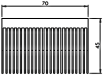
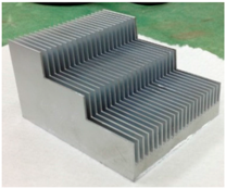
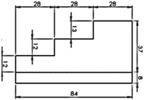
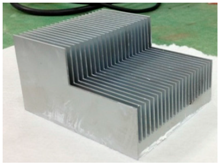
48] experimentally tested the concept using five heat sinks, and the fin patterns include plate fin, step fin (step 1/3, 3 steps), 2-step fin (step 1/2, 2 steps), trapezoid fin (trap 1/3, cutting 1/3 length from the rear end), and trapezoid fin (trap 1/2, cutting 1/2 length from the rear end), respectively. The base area for all test samples is 84 mm × 70 mm with 8 mm base thickness and 37 mm height and the fin material is Aluminum alloy A6061. Some detailed dimensions and photos of the test samples from Chen and Wang [
48] are tabulated in
Table 3.
Through the design of step fin or trap fin, part of the incoming cooler airflow bypasses the front part of the heat sink and is heading toward the rear part of the heat sink. Apparently, a larger temperature difference prevails at downstream, thereby increasing the heat transfer performance of the rear portion. Moreover, the design also illustrates a concept of increasing the effective perimeter of entrance region that promote heat transfer. However, the effect of increasing perimeter in entrance region on the heat transfer performance is only minor. This is because the airflow is inclined into the heat sink rather than perpendicular to the fin surface. However, the proposed approach can effectively raise the temperature difference especially at the rear part of heat sink and the pressure drop can be reduced appreciably due to loss of surface area. However, it also comes at a price of losing effective surface area for heat transfer. Hence, elaborate manipulation of the partial bypass concept is quite essential in practice.
The test results of Chen and Wang [
48] indicated that the step 1/3 and trap 1/3 fin surface give the least and comparable pressure drop. From
Table 3, it appeared that the surface of step 1/3 is 30.9% lower than the original reference plate case and trap 1/3 is only 20.6% lower. From this result, one can conclude that the fin pattern plays the most essential role as far as overall heat transfer performance is concerned. By employing the step change configuration, the sharp change could also result in a larger pressure drop. In addition, the pressure drop is also proportional to the fin morphology and surface area. Their test results indicated that (
ηoh)
trap 1/3 > (
ηoh)
step 1/3 > (
ηoh)
rstep 1/2 > (
ηoh)
trap 1/2 > (
ηoh)
plate, while the effective conductance of trap 1/3 surpasses plate surface by approximately 38% at a fontal velocity of 5 m/s with the corresponding surface reduction of about 20.6%.
From the Newton’s cooling law of Equation (1), the heat transfer enhancement is primarily by either increasing surface area, heat transfer coefficient, or both. Normally the heat transfer coefficient at the entrance region far exceeds that in the rear region for fully developed regime may prevail at the downstream. Yet the mean temperature difference drops alongside the fin surface, hence the temperature difference at the entrance region is much larger when compared to the fully developed region. In this regard, the rear part of the heat sink shows very poor heat transfer performance. To ease the highly uneven heat transfer performance between the entrance and rear part of the heat sink, using trapezoid or step design may remedy the shortcoming by imposing two positive impacts on the heat transfer performance. Firstly, the entering airflow in the upper part flows toward the downstream without touching the fin surface. The bypass airflow contains cooler temperature and it flows downstream with larger temperature difference. Through this manipulation, the colder airflow mixes with the hotter airflow from the lower fin surface, resulting in a comparatively lower temperature at the rear part of the heat sink. Consequently, a larger effective temperature difference prevails at the downstream of the heat sink. Secondly, by using step or trapezoid cut will lengthen the leading edge perimeter of airflow into the fin surface. This eventually brings about a longer entrance region and a higher heat transfer performance.
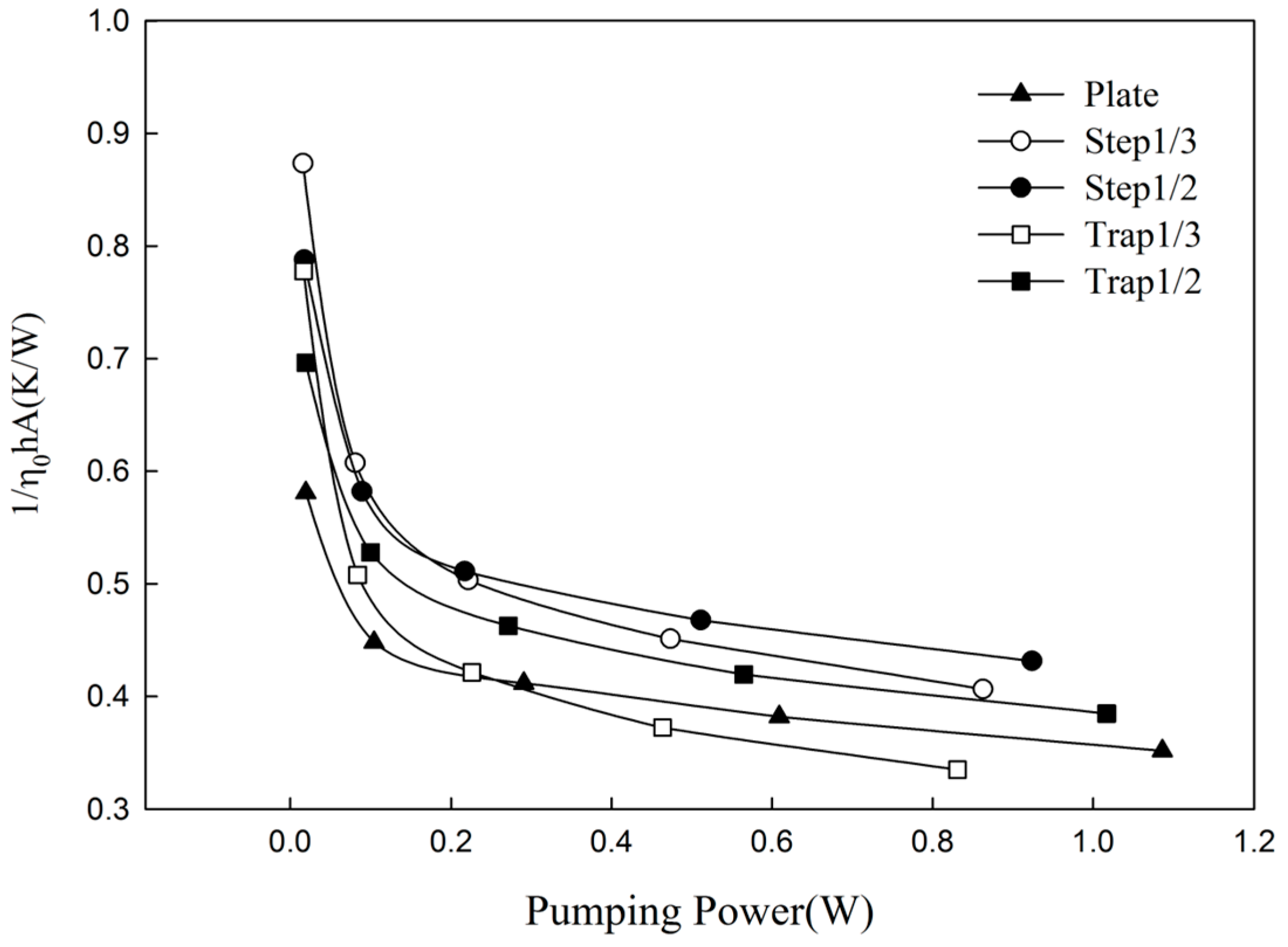
For a fair comparison of the overall performance amid various fin designs, it is essential to balance the thermal conductance, surface area, and pressure drop (pumping power). This can be made available in
Figure 14 in which shows the overall thermal resistance vs. pumping power. As expected, the overall thermal resistance for all the samples decreases when the pumping power is increased. For the same pumping power, say 0.8 W,
Rstep 1/2 >
Rstep 1/3 >
Rtrap 1/2 >
Rplate >
Rtrap 1/3. Notice that
R represents the thermal resistance. The trapezoid design is normally superior to the step design. This is because a longer effective perimeter of entrance region is seen for the trapezoid design, although the perimeter is actually inclined to the airflow, it still offers some positive influence on the heat transfer performance. The resultant thermal resistance of trapezoid 1/3 reveals a 10% lower thermal resistance than the plate fin surface despite its surface is still 20.6% less than the reference plate design. Note that the partial bypass concept is also applicable for heat exchangers subject to dehumidification, see Wang et al. [
49].
5. Augmentation via Material Saving
In electronic cooling design, the use of air-cooling requires sufficient amount of fin surface which may takes up voluminous space and weight of an electronic product. Hence, lowering the volume and weight of the air-cooled heat sink while maintaining the thermal performance are quite important. This is not just from the size concerns but also from the viewpoint of cost issues. Note that cost reduction is normally regarded the most crucial factor for designing typical 3C products (computer, communication, consumer electronics). This concern is especially important in heat sink since it accommodates a comparably large space. In this regard, efforts are made to revisit a compromised fin profile—trapezoidal fin. This is because it contains less mass weight while still retains comparable performance as compared to the traditional rectangular fin profile.
There had been many studies of longitudinal fins having rectangular, triangular, trapezoidal, concave parabolic, and convex parabolic profiles as documented in [
50]. Although fins with variable area profile could provide a more efficient usage of fin material, the corresponding manufacturing process may be comparatively expensive. Hence trapezoidal fin profile is regarded to be a compromise choice to replace traditional rectangular fin as far as cost reduction is concerned. For reassessment of the trapezoid profile, Chen and Wang [
51] proposed an analytical assessment which features a quick estimation of the performance in association with cost reduction. This is essential nowadays for fast evaluations of the suitable taper angle with the performance drop and cost reduction to meet the required demand of the real world. They derived a novel dimensionless parameter—
rt representing the tip to base thickness ratio. Their derivation greatly simplifies the calculation as compared to the equation derived from Kraus et al. [
52]. By introducing the
rt and fin length
b, the taper angle for trapezoidal fin profile then can be defined as Equation (2).
Through this analytical derivation, they had derived the relation amid the weight saving and performance loss. By the calculation of
rt, one can estimate a much lighter heat sink with only a very minor performance loss. This is very important in heat sink markets since a weight saving target is defined with little allowable performance loss. They also derived a closed form solution of the temperature distribution for the trapezoid fin:
where
I and
K are the modified Bessel function solutions of the first kind and second kind, respectively. The subscript 0 and 1 denote order 0 and 1.
M is the dimensionless fin parameter (=
,
t: fin thickness,
b: fin height,
k: thermal conductivity of fin,
h: heat transfer coefficient). The derived equation is also applicable for the temperature distribution of rectangular fin (
rt = 1) and triangular fin (
rt = 0). As the velocity is increased, it can be seen that the tip temperature variation for different
rt is gradually becoming smaller. The temperature distributions merge almost together when
rt > 0.6, suggesting that the performance loss for
rt > 0.6 is negligible while retains a material saving of 20%. Note that the material saving relative to
rt can be shown in the following Equation (4).
When rt = 0, it has a maximum material saving of 50%, and this saving ratio declines with the rise of rt value, starting from rt = 0 of 50% saving down to rt = 1 where no saving at all. Notice that rt = 1.0 represents zero degree angle and it corresponds to the rectangular fin profile.
To validate their analytical approach, they also made two test samples of aluminum heat sinks as shown in
Figure 15. Note that
Figure 15a shows the original rectangular fin design. The size of the heat sink are 90 mm (L) × 90 mm (W) × 25 mm (H) × 25 fins with 1.4 mm fin thickness without any taper angle.
Figure 15b is the trapezoidal fin design having identical dimensions of the rectangular one. The fin thickness is 1.4 mm in the base and 0.7 mm in the tip. Thus,
rt value is 0.5 for this modified design, and a theoretical estimation of material saving by Equation (4) is 25%. The actual measurement of the real weight between these two samples suggests that the actual material saving is 23%. The slight 2% deviation between the theoretical material saving and real weight saving is associated with the removal of four corner heat sink area subject to screw installation. The performance loss is termed as
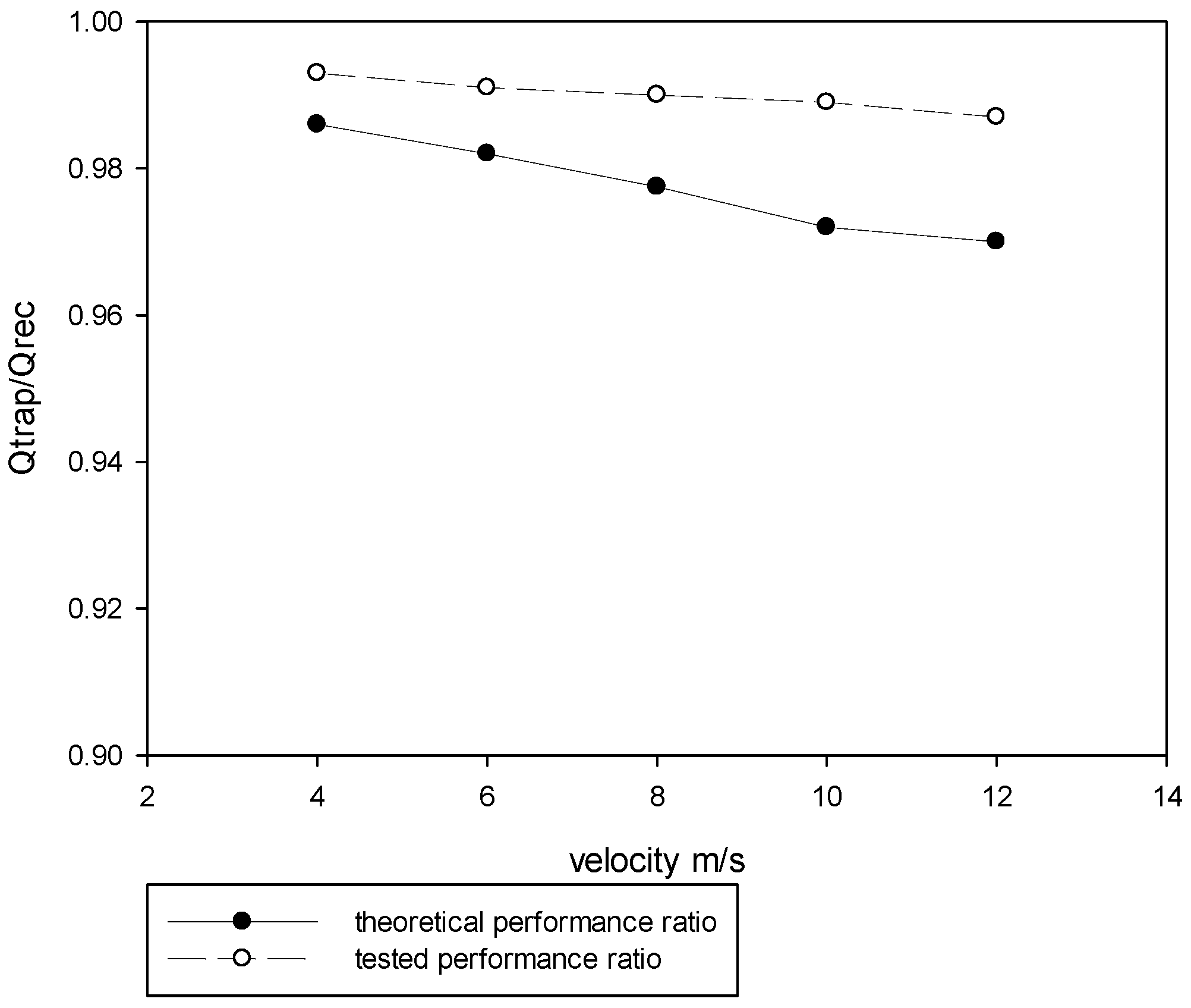
Qtrap/
Qrec vs. frontal velocity and is shown in
Figure 16. As seen in the figure, a material saving of 25% can be achieved with a performance drop as small as 1% for this case when the flow rate is 10 CFM (cubic feet per minute) or 4 m/s air velocity, and with
rt = 0.5. In addition, shown in the figure, the experimental results agree nicely with the theoretical calculation. The rectangular fin heat sink contains a thermal resistance of 0.297 °C/W at a frontal velocity of 4 m/s, while the trapezoidal fin is 0.301 °C/W. The theoretical prediction of the total heat transfer ratio
Qtrap/
Qrec is 0.987 while it is 0.993 for actual test results. The difference amid prediction and measurement is only 0.88%. When the frontal velocity is increased to 12 m/s, the measured
Qtrap/
Qrec is 0.967; while theoretical result is 0.986. The difference is 2.05%. The foregoing concept fulfills the possibility of significant material cost reduction with little performance loss.
As aforementioned in the introduction for the datacenter applications, effective heat removal and affordable pressure drop of a heat sink is quite detrimental. In assessment of the pressure drop across heat sink accompanied with the fan, White [
52] and Holmen [
53] had proposed the methodology to evaluate the friction factor
f applicable for internal pipe flow. The design concept for typical server system is to design heat sink with appropriate thermal performance at the least flow impedance. For rectangular and flat channels, by introducing the hydraulic diameter
Dh (4
Ac/
Ph,
Ac is the cross sectional area,
Ph is the perimeter), the friction factor
f subject to fully developed flow can be evaluated. This estimation is accurate for large scale cooling devices since the majority portion of flow path is fully developed. However, in PC or server applications, the small fin spacing will cause significant pressure loss in the entrance or exit of heat sink due to contraction and expansion. In coping with the entrance and exit losses for developing flow in parallel plate channels, Kays and London [
25] and Webb [
54] had proposed correlations for inlet
Ki and outlet
Ko loss coefficients for parallel plate channels. Notice that inclusion of the entrance and exit loss for accurate estimation of the flow impedance is essential since the size of the air-cooled heat sink is normally small.
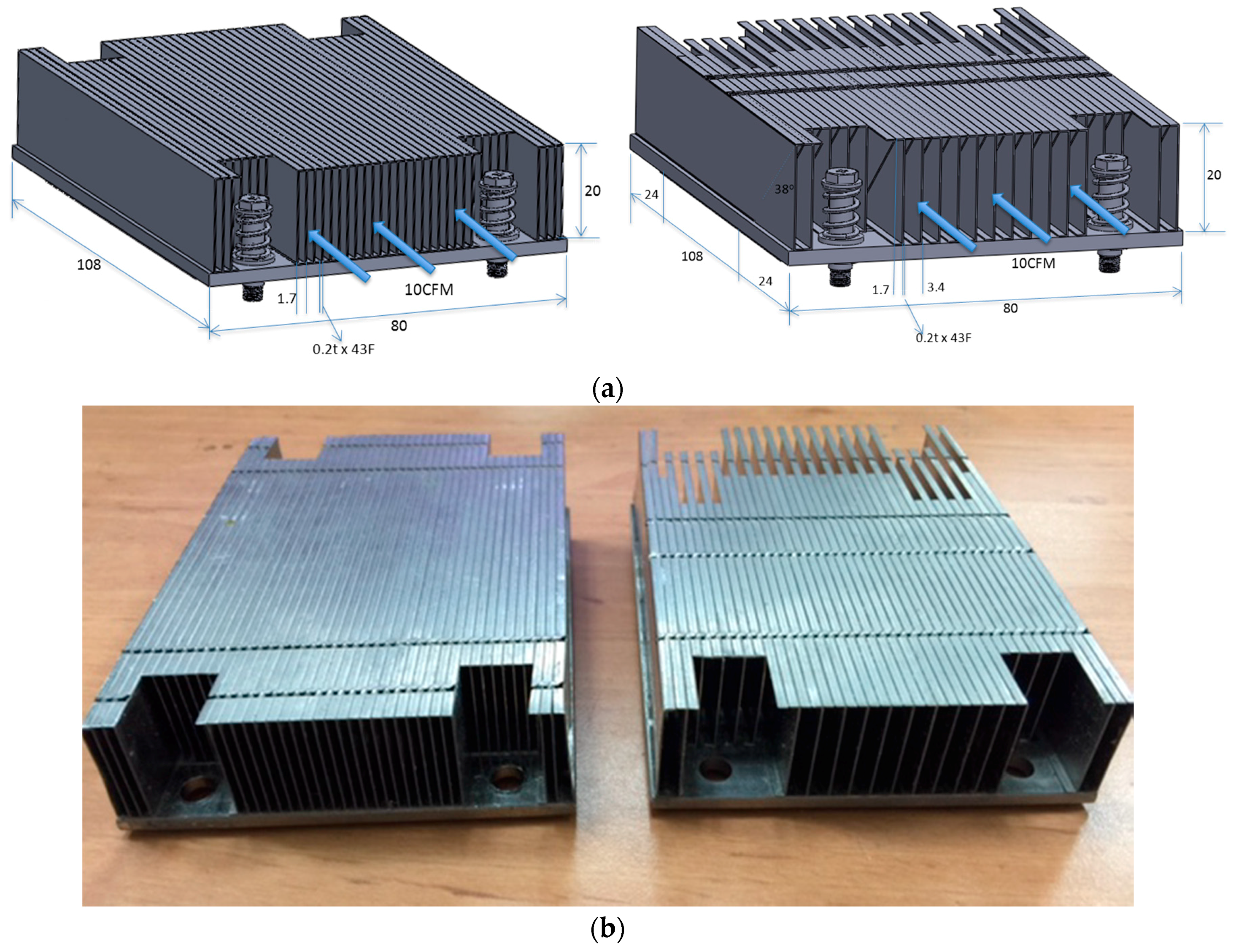
Note that every fan has a P-Q curve to describe the relationship of flow impedance and flow rate. Hence, accurate flow rate can be determined provided that the flow impedance is known. Theoretically, with the same fan, the lower flow impedance of a heat sink; the more airflow is able to pass across the heat sink. Therefore, Chen and Wang [
55] had proposed a novel fin configuration capable of lowering the inlet contraction in exchange of more airflow and they also developed an accurate analytical estimation model that can accurately calculate the pressure drop in developing region. The design concept combines with two different geometrical fins where the fins with odd numbers are rectangular shape, and fins with the even numbers are parallelogram shape. This novel fin module design gains extra 10%–15% airflow without loss in thermal performance from their analytical analysis and experimental verification. The new design is named as IPFM (Interleaved Parallelogram Fin Module). A schematic of the conventional heat sink and the IPFM module and their actual mockup is shown in
Figure 17. The design is different from the existing studies, either numerical or experimental, for which are mainly devoted to conventional rectangular heat sinks [
4,
5,
6,
56,
57,
58] with uniform fin spacing. Chen and Wang [
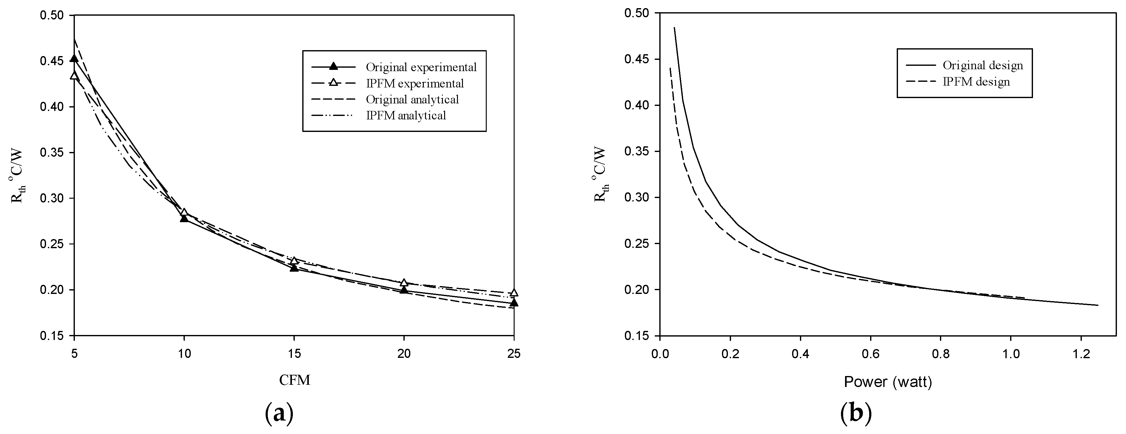
55] showed that their design not only gains the advantages with lower pressure drop but also gains a material saving for less fin surface area. Moreover, the design even depicted a superior heat transfer performance especially in low flowrate region. Keep in mind that heat sink is normally operated in low velocity regime in datacenter server application as far as noise and power consumption is concerned. An analytical assessment of flow impedance and performance between the conventional and IPFM heat sink was conducted and validated by experiment. Their analytical predictions accorded with experimental measurements for both conventional and IPFM design as shown in
Figure 18. In electronic cooling design, especially for cloud server air-cooled heat sink design, the flow pattern is usually laminar with the Reynolds number being operated less than 2000 [
55]. In this regime, the IPFM design shows 8%–12% less surface are than the conventional design when the flow rate is less than 10 CFM; yet the thermal performance is still superior to the conventional design. However, the IPFM module is slightly inferior to the conventional design when the flowrate is raised towards 25 CFM. Within the test range of 5–25 CFM, 10% to 15% lower flow impedance is observed. The smaller fin spacing, the more evident reduction of flow impedance is encountered. The optimization of cutting angle is around 35° for a 10 CFM operation, and it is reduced to 15° at a larger flowrate of 20 CFM.
Another design of heat transfer augmentation via reducing surface area is by cross-cut design. There had been several authors [
59,
60] working on this subject. Kim and Kim [
59] experimentally studied the effects of cross-cuts on the thermal performance of heat sinks. The cross-cuts range from 0.5 to 10 mm. They had tested conventional parallel plate fin, single cross-cut (
Figure 19a), and multiple cross-cut (
Figure 19b). Their results showed that the single cross-cut heat sinks are superior to multiple cross-cut heat sinks in the thermal performance. As shown in
Figure 19c, cross-cut heat sinks outperforms the plate-fin heat sink in most experimental ranges, and it normally reveals an enhancement of thermal performance about 5%–18% relative to the plate-fin configuration. The improvement in thermal performance of cross-cut heat sinks becomes greater as the pumping power increases. One of the explanations about heat transfer augmentation is that the cross-cut promotes a better mixing when the airflow is increased. However, their test data also shows that there exists an optimum of the cross cut. A cross-cut of 10 mm may increase the thermal resistance ratio considerably due to the offsetting effect of losing surface area. Chingulpitak et al. [
60] also conducted similar examinations on the effect of cross-cut both on the overall performance numerically and experimentally. They also found that the thermal resistance of a cross-cut heat sink is 16.2% lower than that of a plate-fin heat sink subject to the same pumping power with a cross-cut of 1.5 mm. Based on their simulation, Chingulpitak et al. [
60] had categorized two kinds of airflow in the cross-cut heat sink, the airflow along the core of the channel and the airflow at the cross-cut region. They found that part of the airflow went into the cross-cut region before striking the next plate fin and it returns to the channel. This flow mechanism results in mixing of the airflow between adjacent channels. In addition, it can be clearly seen that the recirculation zone may occur at the trailing edges of the fins as shown in
Figure 20. Yet this airflow disturbance at the cross-cut regions increases with rising air velocity and cross-cut length, this can explain in part that the cross-cut may be especially useful in high velocity region. However, one should bear in mind that the fin thickness for both foregoing studies is 1 mm which may be much larger than those used in electronic cooling. Additionally, electronic cooling may also require low velocity operation that may further jeopardize the benefits of cross-cut.

