Article

The Application of an Optimised Proportional–Integral–Derivative–Acceleration Controller to an Islanded Microgrid Scenario with Multiple Non-Conventional Power Resources

by
Prasun Sanki
1,
Sindhura Gupta
1,
Srinivasa Rao Gampa
2,*,
Amarendra Alluri
2,
Mahesh Babu Basam
2 and
Debapriya Das
3
1
Department of Electrical Engineering, Netaji Subhash Engineering College, Kolkata 700152, West Bengal, India
2
Department of Electrical & Electronics Engineering, Seshadri Rao Gudlavalleru Engineering College, Gudlavalleru 521356, Andhra Pradesh, India
3
Department of Electrical Engineering, Indian Institute of Technology Kharagpur, Kharagpur 721302, West Bengal, India
*
Author to whom correspondence should be addressed.
Inventions 2025, 10(6), 99; https://doi.org/10.3390/inventions10060099
Submission received: 12 September 2025 / Revised: 22 October 2025 / Accepted: 27 October 2025 / Published: 3 November 2025
(This article belongs to the Special Issue Recent Advances and Challenges in Emerging Power Systems: 2nd Edition)

Abstract

Presently, numerous non-conventional power resources have been applied in power system networks. However, these resources are very effective in islanded microgrid (IMG) scenarios for addressing numerous operational challenges. Additionally, it is observed that the power output of most of these resources is environment-dependent and intermittent in nature. This intermittency causes a power imbalance between the overall generated power and the load demand, which results in an undesired frequency oscillation. In order to address this unwanted frequency fluctuation, this research work proposes power–frequency synchronisation considering an islanded microgrid scenario under numerous non-conventional power resources. The major contribution of this work includes implementing a suitable and optimised control scheme that effectively controls diverse power system disturbances and various uncertainties. A Fick’s law optimisation-based proportional–integral–derivative–acceleration controller (PIDA) is implemented under this proposed power scenario. Additionally, an extensive performance assessment is conducted considering different simulation test cases in order to verify the performance of the proposed control topology. Further, the effectiveness of the suggested power network is tested on a 33-bus radial distribution network. Finally, simulation results are shown to show the effectiveness of the proposed control scheme for the efficient operation of the microgrid in achieving the desired performance under the diverse operating conditions.

1. Introduction

Modern power systems utilise numerous renewable-energy-based power producers (REPPs) to satisfy the ever-increasing power demand. In earlier situations, consumers had to be completely dependent on traditional power producers (TPPs), such as thermal-power-generating units (TPGUs) and hydro-power-generating units (HPGUs). However, among these power resources, the maximum power was produced from TPGUs, utilising harmful fossil fuel. This resulted in undesired environmental degradation and enormous emissions of greenhouse gases. In order to deal with the abovementioned concerns, currently, non-traditional power producers (NTPPs) like solar-power-generating units (SPGUs), wind-power-generating units (WPGUs), tidal energy (TE), and geothermal energy (GTE) are utilised abundantly. Further, these NTPPs are widely operated either with TPPs in grid-connected mode or operated autonomously in an islanded mode microgrid operation [1,2]. However, it is observed that most NTPPs depend on environmental conditions, and their generated output power is intermittent in nature. This power intermittency is responsible for causing a mismatch between the load-demanded power and the generated power available from NTPPs. Further, it is also noticed that the mismatch of power results in sustained frequency oscillations in the respective power systems. This frequency oscillation appears as a vulnerability when the system is operated in islanded conditions [3,4,5]. Therefore, during islanded mode operation, diesel generator systems (DGSs) and energy storage units (ESUs) are widely utilised to enhance the power quality by regulating an adequate power–frequency balance. Extensive research work reveals that islanded microgrid operations are very effective in remote areas or regions where there are geographical limitations and regions that traditional power systems are unable to reach. Further, in these types of microgrid scenarios, the diverse mixing of different power-generating units (PGUs) can be observed. Therefore, special attention must be provided to ensuring a proper equilibrium between the power and frequency of the system, ensuring optimal automatic generation control (AGC) operation [6].
Over the years, numerous research works have been conducted addressing power–frequency synchronism (i.e., AGC) in different power system configurations. It should be noted that mostly, these investigations were performed considering interconnected power system scenarios, including TPPs and NTPPs and mixing both power-generating units [7,8,9,10,11]. Compared to this, less attention has been given to research that address AGC issues under the islanded microgrid scenario. Therefore, a wide scope of research opportunities still exists considering this type of power system configuration. Practically, REPPs, mainly NTPPs, are widely utilised in islanded power system scenarios. On the other hand, among diverse NTPPs, SPGUs and WPGUs are extensively employed in islanded power system conditions. Furthermore, it should be noted that their participation is fully dependent on environmental conditions, and the output power from these power producers is intermittent in nature. Apart from SPGUs and WPGUs, aqua electrolyser (AE)-based fuel cell units (FCUs) have also been suggested by some researchers as PGUs in an islanded power system scenario [12,13]. In these circumstances, it should be noted that SPGUs and WPGUs do not take part in primary frequency control (PFC) or secondary frequency control (SFC) operations [14,15]. Therefore, in an islanded microgrid scenario, to assure stable and secure AGC operations, some components are essential to assist in PFC and SFC operations. Accordingly, it is observed that in many cases, small TPGUs, diesel engine generating units (DGUs), and microturbine units (MTUs) have been incorporated to perform the required PFC and SFC operations [16,17,18]. In addition, ESUs play a crucial role in the proper power management under an islanded microgrid scenario. When extra power is available from SPGUs and WPGUs, the ESUs store energy, and they dispatch this energy when there is sudden load demand. Therefore, the ESUs play an important role in proper, stable, and secure power–frequency management [19,20,21]. Numerous ESUs like flywheel ESUs (FESUs), battery ESUs (BESUs), ultra capacitors (UCs), and redox-flow batteries (RFBs) are already utilised to address power–frequency synchronisation issues [22,23]. Further, the extensive integration of NTPPs in the power network often reduces the overall inertia constant, resulting in a power system stability problem. In such systems, often ESUs are integrated to accomplish the required virtual inertia control (VIC) operation [17,24]. Therefore, it can be stated that numerous PGUs have been introduced to date to achieve stable and secure islanded microgrid functioning. The contribution of a suitable controller is indispensable in NTPP-based power systems to achieve the desired performance. In this regard, a detailed discussion is presented considering numerous control schemes in the following manner.
In the case of practical scenarios, a suitable controller is essential to ensure adequate power–frequency synchronisation. Over the years, numerous control schemes have been adopted to address the AGC operation associated with different power system scenarios. Some authors have proposed control techniques based on conventional PID controllers and fractional order PID controllers for solving the frequency regulation problem under load disturbance conditions. The conventional control schemes from the literature can be noted as conventional linear quadratic gaussian (LQG) and modified LQG with linear quadratic integral (LQI) control schemes [16], centralised proportional integral derivative (PID) controller [25], multistage PID controller [26], fractional order PID (FOPID) controller [23,27], and integral based sliding mode control (I-SMC) [28]. Recently many authors combined fuzzy logic with conventional control schemes and proposed techniques for regulating frequency deviation problems of AGC operation. They can be addressed as follows: fractional order fuzzy pre-compensated PDPI (FO-FPPDPI) controller [29], fuzzy PIDF (1 + PI), PIDF and fuzzy-PID controllers [30], cascade fractional order hybrid controller combining FOTID and 3DOF-PID [31], disturbance-observer-based controller (DOBC) [32], and fuzzy-PID controller [33] and cascade double-input interval type 2 fuzzy logic controller with PI–PD controller [34]. In addition to the application of numerous control schemes, the model predictive control [MPC] scheme is also utilised to address frequency regulation issues [22,35]. Regarding the same, the implementation of artificial intelligence (AI)-based control schemes is also becoming increasingly popular among researchers [36,37]. Recently, for tuning the controller gain parameters, most of the authors used various metaheuristic optimisation techniques. Some of the popular techniques are the cheetah optimiser (CO) [13], improved centripetal force-gravity search algorithm (CF-GSA) [14], improved sine cosine algorithm (i-SCA) [20], squirrel search algorithm (SSA) [22], chaotic chimp-mountain gazelle optimiser (CCMGO) [23], quasi-oppositional harmony search (QOHS) algorithm [25], moth-flame optimisation (MFO) [26,33], teaching learning based optimisation (TLBO) [27], particle swarm optimisation (PSO) [28], multi-objective salp swarm algorithm (MSSA) [29], hybrid whale optimisation algorithm (HWOA) [31], salp swarm algorithm (SSA) [34], genetic algorithm (GA) [35], and differential evolution (DE) [38] algorithm. The aforementioned controllers are predominantly designed for specific power system objectives. Therefore, the impacts of diverse operating conditions on system performance are insufficiently addressed. Considering the ongoing moderations and structural modifications, the designing of fast, precise, and dynamic controllers remains an indispensable necessity. In order to address different computational and designing bottlenecks, the (PIDA) controller performs extremely well. Hence, the performance of the PIDA controller is evaluated in this research work.
So far, an exhaustive literature review has been presented considering various aspects of AGC in islanded microgrid scenarios. Additionally, a detailed discussion regarding various suggested control schemes is presented to accomplish seamless power–frequency balance. Although several controller applications with the implementation of different optimisation techniques are presented in various research works such as [26,27,32], there is still a scope left to introduce an effective controller that is flexible, simple, and very easy to use. Additionally, fast convergence and superior responses compared to other available optimisation techniques are the reasons behind selecting a proper metaheuristic technique. Therefore, in the present work, a Fick’s law optimisation (FLO)-based PIDA controller is proposed for efficient operation of AGC with minimum frequency fluctuations under the uncertain operating conditions of an islanded microgrid scenario. Numerous simulation test scenarios are presented and based on the obtained results, and the superiority of the adopted control scheme is established in terms of precise frequency regulation. The simulation results are shown to demonstrate the effectiveness of the proposed control scheme. Considering the critical explorations as well as analysing the bottlenecks, the point-wise contributions of the paper are as follows:
  • Implementation of a novel method: In this paper, a recently proposed optimisation technique is adopted in the presence of a modified PID controller. Therefore, based on the earlier discussion, the Fick’s law optimisation (FLO)-algorithm-based PIDA controller is proposed for the SFC operation application in an islanded microgrid scenario. Compared to the fractional order-based and the fuzzy logic-based control schemes, the PIDA controller is very simple and easy to implement for practical applications. Based on the detailed literature review and the best of the authors knowledge, the application of the FLO-algorithm-tuned PIDA controller is adopted for the first time in this islanded microgrid scenario.
  • Innovative initialisation process: Generally, in a metaheuristic technique, the initialisation process is performed randomly. However, in this research work, the gain parameters of the PIDA controller are initialised using the stability range of a pole-zero plot analysis of the controller gain parameters for generating the initial population for the metaheuristic technique instead of choosing them randomly.
  • Selection of effective control scheme: In the last few decades, it has been observed that the PID control scheme has gained extreme popularity among research engineers and industrialists due to its simplicity and versatility. However, considering the evolving power system scenario with frequent NTPP integration, the PIDA controller is proposed in this research work. The additional acceleration term in the PIDA controller will be helpful to achieve a faster response, better disturbance rejection capability, proper damping, and stability of the frequency of oscillations and to enhance accuracy. Practically, the PIDA controller is a modified version of a simple PID controller with much improved dynamics. Accordingly, a critical exploration is carried out in this work considering the frequency regulation issue in the presence of the PIDA controller.
  • Detailed performance analysis: Additionally, detailed analytical studies are performed considering numerous simulation studies to replicate a realistic islanded microgrid scenario. In this regard, uncertainty and randomness associated with power generation from SPGUs, WPGUs, and various variations in load demand are considered. In order to evaluate the efficacy of the proposed control scheme, a comparative analysis with the latest research works is presented.
  • Validation of the proposed configuration: Furthermore, the performance analysis of the proposed control scheme is carried out on a standard 33-bus radial distribution network. This performance analysis is required to understand the system behaviour under a standard power system network to establish appropriate functioning of the proposed control scheme under the chosen islanded microgrid scenario.
The rest of the manuscript is structured as follows: Section 2 presents the detailing of the materials and methods utilized in this research work. Further, the result analysis is discussed in Section 3, and the concluding remarks are furnished in Section 4.

2. Materials and Methods

2.1. Power System Components

This research work presents a single-area microgrid-based power system consisting of different power-generating units. The present power system scenario consists of a solar-power-generating unit (SPGU), a wind-power-generating unit (WPGU), a diesel engine generating unit (DGU), and three energy storage units (ESUs). The battery energy storage unit (BESU), flywheel energy storage unit (FESU), and electric vehicle unit (EVU) performing as vehicle-to-grid (V2G) technology are the three ESUs considered. The SPGUs, WPGUs, and ESUs utilise power electronic converters as well as various electrical line components for transferring the power seamlessly to the grid. In this scenario, a first-order transfer function model is used as the grid interconnecting network (GIN). In practical systems, some delay is often observed while integrating DGUs. Therefore, in this work, to represent the overall DGU participation more realistically, a delay unit is accompanied by the DGU transfer function. An elaborative schematic diagram of the arrangement of the NTPPs, ESUs, and the applied control scheme in the islanded microgrid scenario is presented in Figure 1. It is assumed that 70–80% of the load demand is fulfilled by the renewable NTPPs and the ESUs. However, the remaining 20–30% is shared by the remaining units. The limiters presented in Figure 1 indicate the maximum and the minimum limits of the power fluctuations of the individual sources as well as ESUs. In this configuration, the SPGUs and WPGUs are not participating in PFC as well as SFC operations. The DGU contribution is pivotal in this regard to accomplish the necessary PFC and SFC operation. Additionally, 1% step load disturbance (SLD) at 85% of the full load condition is considered for analysis of the system performance. A detailed discussions of the system configuration considering various power-generating units (PGUs) as well as ESUs are presented in the following subsections. The adopted parametric values of the various units are presented in Appendix A.

2.1.1. Solar-Power-Generating Unit (SPGU)

Considering the prevailing power system scenario, SPGUs are the most convenient and ecoconscious renewable PGU (RPGU) to overcome the bottlenecks of clean energy expansions. Over the years, the progressive improvement in research and development has led to a substantial reduction in the per kW cost of power generation by SPGUs [25,29,33]. SPGUs are becoming the most suitable alternative to traditional power generators because of their effective performance and the ease of availability. Practically, the solar irradiation ϕ and atmospheric temperature T m are the pivotal factors of net power generation from SPGUs. Therefore, intermittency or discontinuity are the concerning aspects of these generating units. Further, for seamless grid integration and for accurate power utilisation, the interconnection of different power converters, electrical equipment, and power tie lines is imperative. In this work, to resemble a practical situation, an additional transfer function is incorporated to discern the impact of these interconnecting components. The mathematical expression for the output power from the SPGU is given by Equation (1).
P S P G U = η ϕ A c 1 0.005 ( T m + 25 )
The corresponding linearised transfer function expression combining the SPGU and GIN is expressed by Equation (2).
G S P G U = Δ P S P G U ( s ) Δ S I ( s ) = K P V 1 + s T P V × 1 1 + s T G I N = K P V 1 + s T P V × G G I N
where K P V and T P V are the gain parameter and the operating time constant of the SPGU; Δ S I represents the differential change in the solar irradiation. Further, T G I N is the operating time constant of the GIN unit. Usually, it is considered a very small value (nearly 10−3) to replicate its faster dynamical behaviour. Based on the mathematical modelling by the above equations, the detailed transfer function model is depicted in Figure 1.

2.1.2. Wind-Power-Generating Unit (WPGU)

Widespread adoption and scalability have turned wind-power-generating units (WPGUs) into the second-largest RPGUs. The output power of a wind turbine is predominantly controlled by the wind speed Vs and the power coefficient C w p . As a result, the power contribution of WPGUs varies significantly due to the random fluctuations in the wind speed. Therefore, similar to SPGUs, power generation from WPGUs is nondispatchable and intermittent in nature [16,29]. The standard mathematical power generation expression of WPGUs is formulated by Equation (3).
P W P G U = 0.5 ρ w p π V s 3 R w p 2 C w p ( γ , δ )
where the air density is represented by ρ w p and the radius of the turbine blade is expressed as Rwp. Further, the power coefficient can be formulated as a function of the tip speed ratio γ and blade pitch angle δ (in degrees), which can be expressed by Equations (4) and (5), respectively.
C P ( γ , δ ) = 0.22 ( 16 γ k 0.4 δ 5 ) e 12.5 γ k
1 γ k = 1 γ + 0.08 δ 0.035 δ 3 + 1
The conventional transfer function model of the WPGU can be represented by Equation (6).
G W P G U = Δ P W P G U ( s ) Δ V W ( s ) = K WT 1 + sT WT × 1 1 + sT GIN = K WT 1 + sT WT × G GIN
where K WT and T WT are the turbine gain parameter and operating time constant, respectively. In the adopted power system, the wind turbine transfer function is cascaded with G GIN to obtain the complete power output expression of the WPGU. Based on the mathematical representation, the detailed transfer function model of the WPGU is depicted in Figure 1.

2.1.3. Diesel Engine Generating Unit (DGU)

The SFC operation under the AGC scenario is widely accomplished by the DGUs in decentralised power systems. Their ability to respond quickly and reliably gained prominence for them as the standby generating units to manage critical loads during the suboptimal availability of NTPPs. The power–frequency deviations due to the intermittence nature of the RPGUs are often controlled by these reserve generators. The DGU is used to perform the secondary frequency regulation, and its mathematical model is represented by the first-order transfer function as described in Equation (7). In order to replicate a practical scenario, an additional delay unit is also assimilated with the considered transfer function [12,14].
G D G U = Δ P D G U ( s ) Δ u D G U ( s ) = 1 1 + sT DGU × K D 1 + sT D
where TDGU is the time constant of the diesel generator. KD and TD are the gain and the operating time constant of the delay unit of the DGU, respectively. Based on the transfer function model, the detailed system configuration is depicted in Figure 1.

2.1.4. Energy Storage Unit (ESU)

In order to maintain the grid resilience under different diversities and contingencies, various forms of ESUs are now accompanied with SPGUs, WPGUs, and DEGUs [12,16,29]. The short-term generation and load mismatches due to the frequent variations in intermittent energy sources could be effectively balanced with the ESUs. The rapid charging and discharging property of these storage units makes them suitable for secondary frequency regulation and for compensating the tie-line power deviations under AGC operation. This work includes the two most common forms of ESUs, i.e., BESUs and FESUs, in the proposed power system to regulate the balance between generated power and load demand. The GIN blocks are interconnected with the BESU and FESU to represent them more realistically. The corresponding transfer function equations of the BESU and FESU are expressed by Equations (8) and (9), respectively. This work also incorporates the V2G concept of the EVU, and the corresponding transfer function model of the EVU is expressed by Equation (10).
G B E S U = Δ P B E S U ( s ) Δ f ( s ) = K BMS 1 + sT BMS × 1 1 + sT GIN
G F E S U = Δ P F E S U ( s ) Δ f ( s ) = K FW 1 + sT FW × 1 1 + sT GIN
G E V U = Δ P E V U ( s ) Δ f ( s ) = K EVU 1 + sT BCU × 1 1 + sT GIN
where KBMS and TBMS are the gain and time constant parameters of the BESU, KFW and TFW are the gain and time constant parameters of the FESU, and KEVU and TEVU are the gain and time constant parameters of the EVU. Based on the transfer function models, the detailed system configuration is depicted in Figure 1. All the parameter values are presented in Appendix A.

2.1.5. Generation–Load Mismatch Unit (Power System Block)

The uncertain and unpredictable nature of load demand is the prime reason for power imbalance under the practical power system scenario. The corrective actions through AGC are required to maintain the system operating frequency and power balance within the scheduled limits. Equation (11) shows the difference between generation ( P G ) and load demand ( P L ), and as the difference between them increases, the burden on the regulating units increases and ultimately compromises system stability. Technically, excess generation, i.e., when P G > P L , results in a frequency rise ( + Δ f ), and any deficiency in generation, i.e., when P G < P L , causes a frequency drop ( Δ f ). The ratio of frequency deviation to load demand deviation is shown in Equation (12).
Δ P D E V = P G P L
Δ f Δ P D E V = K IMG 1 + sT IMG
Equation (12) is the main deciding factor for the frequency deviation in the power network. The generalised transfer function configuration of this power system block is presented in Figure 1, where KIMG and TIMG are the gain parameter and the time constant parameter of the islanded microgrid scenario. Further, the parameter values of this power system block vary with loading conditions, which directly affects the system dynamics.

2.2. Controller Design and Objective Function (ϒ) Selection

To date, plenty of efficient controllers have been adopted in various engineering applications to maintain system stability, accuracy, and performance under different contingencies. Among all of these, different combinations of PID controllers have gained global popularity due to their simplicity, versatility, and enriched effectiveness. P controllers offer immediate current error correction, I controllers eliminate the steady state error based on past records, and D controllers predict the future behaviour to ensure stable and reliable system operation. However, it has been observed that traditional PID controllers may fall short in responding to high precision and dynamic requirements. Therefore, an advanced form of PID, i.e., the PIDA controller, is suggested in this work by adding an accelerating term “A” along with the existing controller. The additional accelerating factor of the proposed PIDA controller contains a second-order derivative of the error to handle the sudden changes in system frequency deviations under AGC operation. It effectively handles the fast-developing uncertainties due to load and energy source uncertainties. The mathematical expression of the proposed PIDA controller is given by Equation (13).
C ( s ) = k P + k I s + s k D + s 2 k a
where k P , k I , k D , and k a represent the proportional, integral, derivative, and acceleration gain parameters of the proposed PIDA controller. The basic configuration of this adopted controller topology is presented in Figure 1 in Section 2.1.
The prime objective of this research work is to regulate the system frequency deviations within the desired limits under the power system diversities. Accordingly, a suitable controller design and tuning of the gain parameters are considered as the essential criteria. The FLO algorithm is utilised to obtain the optimised gain parameters of the PIDA controller in the presence of different performance indices, i.e., the integral square error (ISE), integral time square error (ITSE), integral absolute error (IAE), and integral time absolute error (ITAE) techniques. The mathematical expressions of the adopted objective function ( ϒ ) under different performance indices are presented by Equations (14)–(17).
ϒ I S E = 0 T S Δ f 2 d t
ϒ I T S E = 0 T S t Δ f 2 d t
ϒ I A E = 0 T S | Δ f | d t
ϒ I T A E = 0 T S t | Δ f | d t
where Δ f represents the frequency deviation of the control area under power system diversities. A detailed discussion of the adopted FLO technique is presented in the following section.

2.3. Fick’s Law Optimisation (FLO)

Based on the principle of Fick’s law of diffusion, a population-based optimisation technique is suggested in this work to evaluate the gain parameters of the proposed PIDA controller. Fick’s law optimisation (FLO) [39,40] functions in three different stages, i.e., diffusion (DF), equilibrium (EQ), and steady state (SS) stages to finalise a stable position of a molecule in any medium. In this algorithm, primarily in the DF stage, the entire search space is divided into two distinct sections with different concentration levels. The particles of the high-concentration region rush towards the low-concentration region. However, based on the difference in the concentration of the layers, the mobility of molecules differs. In the EQ stage, the difference in the layer concentrations will be minimised, and the particles will try to find a stable position in their respective mediums. Finally, in the SS stage, one barrier appears between the two concentration levels, and due to this barrier, the molecules will come to a suitable stable position in their respective concentration levels. Further, in the following section, the detailed mathematical formulation of FLO is delineated.
At the beginning, a randomly generated sample population set A is considered for the optimisation process, as presented in Equation (18), where the population size is presented as S, the problem dimension is denoted as D, and i represents the ith problem dimension.
A = A 1 , 1 A 1 , i A 1 , ( D 1 ) A 1 , D A 2 , 1 A 2 , i A 2 , ( D 1 ) A 2 , D A ( S 1 ) , 1 A ( S 1 ) , i A ( S 1 ) , ( D 1 ) A ( S 1 ) , D A S , 1 A S , i A S , ( D 1 ) A S , D
Further, the total population P is divided into two groups based on their concentrations and sizes of P1 and P2. The movement of each sample from level P1 to P2 is governed by a non-linear transfer function, as expressed by the following Equation (19).
T f t = sinh ( t / T ) c 1
where T represents the total number of iterations, t represents the present iteration, and c1 is a constant. As shown in Equation (20), the movement of samples from one stage to the other based on FLO have some predefined threshold values T f t .
n k t = T f t < 0.9 D F T f t 1 E Q T f t > 1 S S
When the concentration of P2 is higher than P1, samples move from P1 to P2. Initially, in the DF stage the movement of the samples from P1 to P2 is computed by Equation (21).
n T D F = n P 1 × x 1 × ( c 4 c 3 ) + n P 1 × c 3
where n P 1 presents the total number of samples present in the P1 stage, and c 3 and c 4 are constant values. The x 1 is a random value in between 0 and 1. The remaining samples n R D F in P1 are given by Equation (22).
n R D F = n P 1 n T D F
Therefore, n T D F samples move from the P1 stage to P2 stage, and their positions are updated by Equation (23).
n T E Q t + 1 = n E Q , P 2 t + D f P 1 , P 2 t × F × c 4 × n E Q t × ϕ P 1 , P 2 t n T E Q t + 1
where n E Q , P 2 t is the equilibrium position of the samples in P2, D f P 1 , P 2 t is the direction factor that changes according to the direction of movement of the samples in their respective search areas, c 4 is a constant, and F is the direction of flow, which can be determined by Equation (24).
F = exp c 5 T f t x 1
where c 5 is a constant term. Further, the diffusion flux ϕ P 1 , P 2 t is expressed as Equation (25).
ϕ P 1 , P 2 t = e d c P 1 , P 2 t d g P 1 , P 2 t
where ‘e’ represents the effective emissivity and d c P 1 , P 2 t / d g P 1 , P 2 t represents the concentration gradient. Furthermore, the left-out samples in P1, i.e., n R D F , update their positions according to the expression, as represented by Equation (26).
n R D F t + 1 = n E Q , P 1 t r a n < 0.8 n E Q , P 1 t + F × c 6 × ( u l ) + l r a n < 0.9 n R D F t + 1 o t h e r w i s e
where n E Q , P 1 t is the equilibrium position in stage P1 and u and l are considered as the upper and lower boundaries of the entire search space. In the EQ stage, the samples that have already been transferred from P1 to P2 will try to update their positions to an equilibrium point in P2 according to Equation (27).
n D F t + 1 = n E Q , P 2 t + ( Q E Q , P 2 t × n D F t ) + Q E Q t × S E Q t × n E Q , P 2 t n D F t
Here, Q E Q t represents the relative quality of the P2 stage, and S E Q t represents the motion step of the samples in the DF stage. S E Q t can be further expressed as Equation (28).
S E Q t = exp F F E Q t F F T D F t + e p s
where F F E Q t is the fitness factor in the P2 layer and F F T D F t is the computed fitness score of a sample in the P2 layer in the EQ stage. Finally, in the SS stage, the samples in their respective concentration layer will update their positions to a stable point according to Equation (29).
n E Q S S t + 1 = n S S t + ( Q S S t × n E Q S S t ) + Q S S t × S S S t × n S S t n E Q S S t
In Equation (29), n S S t represents the steady state location of a sample, Q S S t represents the relative quality of the respective medium, and S S S t is the motion step of the samples in the SS stage. S S S t can be further expressed by Equation (30).
S s s t = exp F F S S t F F T S S t + e p s
where F F s s t is the fitness factor and F F T s s t is the computed fitness score of a sample in the SS stage. Additionally, the generalised pseudo-code of the FLO is presented as follows Algorithm 1.
Algorithm 1: Fick’s Law Optimisation Algorithm [39]:
Initialisation;
  Initialise the parameters (D, c1, c2, c3, c4, c5, c6);
  Initialise the total samples Ai (i = 1, 2, 3,……n);
  Divide the total population into two layers of different concentrations, i.e., P1 and P2;
for p = 1:2 do
  Compute the fitness factor of each sample in the layers;
  Find the best sample in each layer;
end for
while   F F F F max  do
   if   T f t < 0.9  then
    for q = 1:nq do
       Calculate   S s s t
       Update   n E Q S S t + 1
     end for
   else   if   T f t < r a n d  then
    for q = 1: nq do
       Calculate   S E Q t
       Update   n R D F t + 1
     end for
   else
    Calculate F
     Determine   n T D F
     Calculate   n T E Q t + 1
     Update   n R D F t + 1
     Update   n D F t + 1
     Update   F F
   end if
end while
Return the best solution.

3. Results

In this section, an extensive result analysis has been carried out considering numerous test scenarios in an islanded microgrid environment containing renewable energy sources under different loading conditions such as SLDs and random load disturbances (RLDs). A performance analysis is also carried out considering the uncertainties in power output conditions of the NTPPs (especially the WPGU) along with the uncertain load variations. These uncertainties are implemented in the simulation case studies to mimic practical scenarios. Further, a detailed comparison assessment is shown considering recently proposed control topologies. The investigation is further extended considering the suggested islanded microgrid-based power system operation considering a 33-bus radial distribution network [41] as a test system. In this connection, a generalised overview of all the test cases is presented in Table 1. A detailed discussion on the implemented case studies is furnished in the subsequent subsections.

3.1. System Performance Analysis Considering 1% SLD Condition

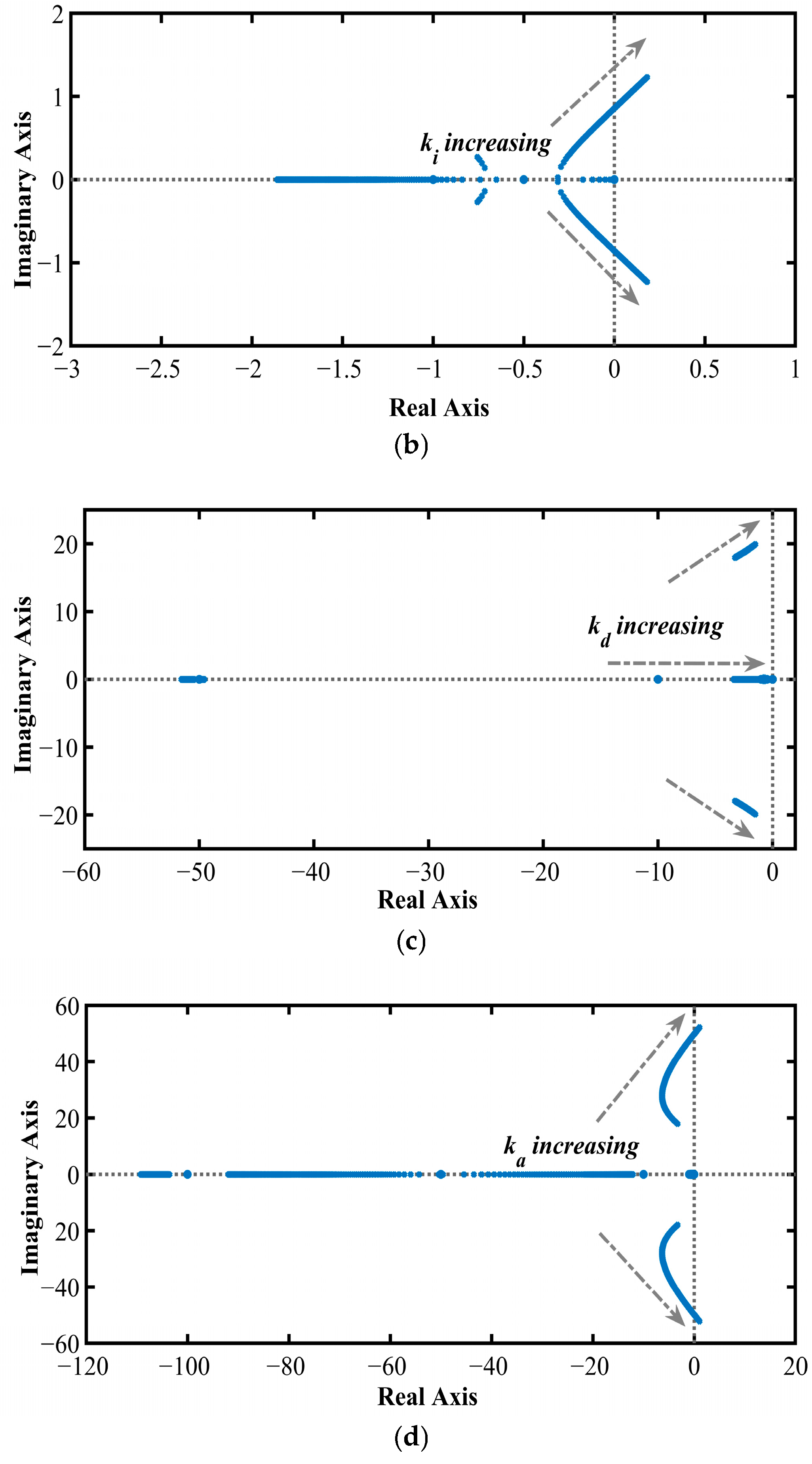
In this subsection, a detailed performance analysis of the islanded microgrid scenario is presented under the 1% SLD condition with an 80% nominal loading condition. Generally, step signals inject an infinite frequency signal, which is the best practice to evaluate the system response. Therefore, SLD is considered in order to perform the performance assessment. In this test case, the power output value of the SPGU and WPGU is considered as 0.002 pu, A comparative analysis is further carried out considering different controller topologies. In this regard, PI, PID, and FOPID controllers are considered along with the proposed PIDA controller. All the gain parameters of the considered controllers are tuned using the same metaheuristic technique, i.e., the FLO technique. For the proposed PIDA controller, the range of the controller gain parameters is chosen to be in between 0 and 20. According to this range, pole-zero plots of each gain parameter are obtained. Considering the stable operating region from the plots, the gain parameter ranges are selected for the initialisation process of the proposed FLO algorithm. In this regard, the pole-zero plots are shown in Figure 2a–d.
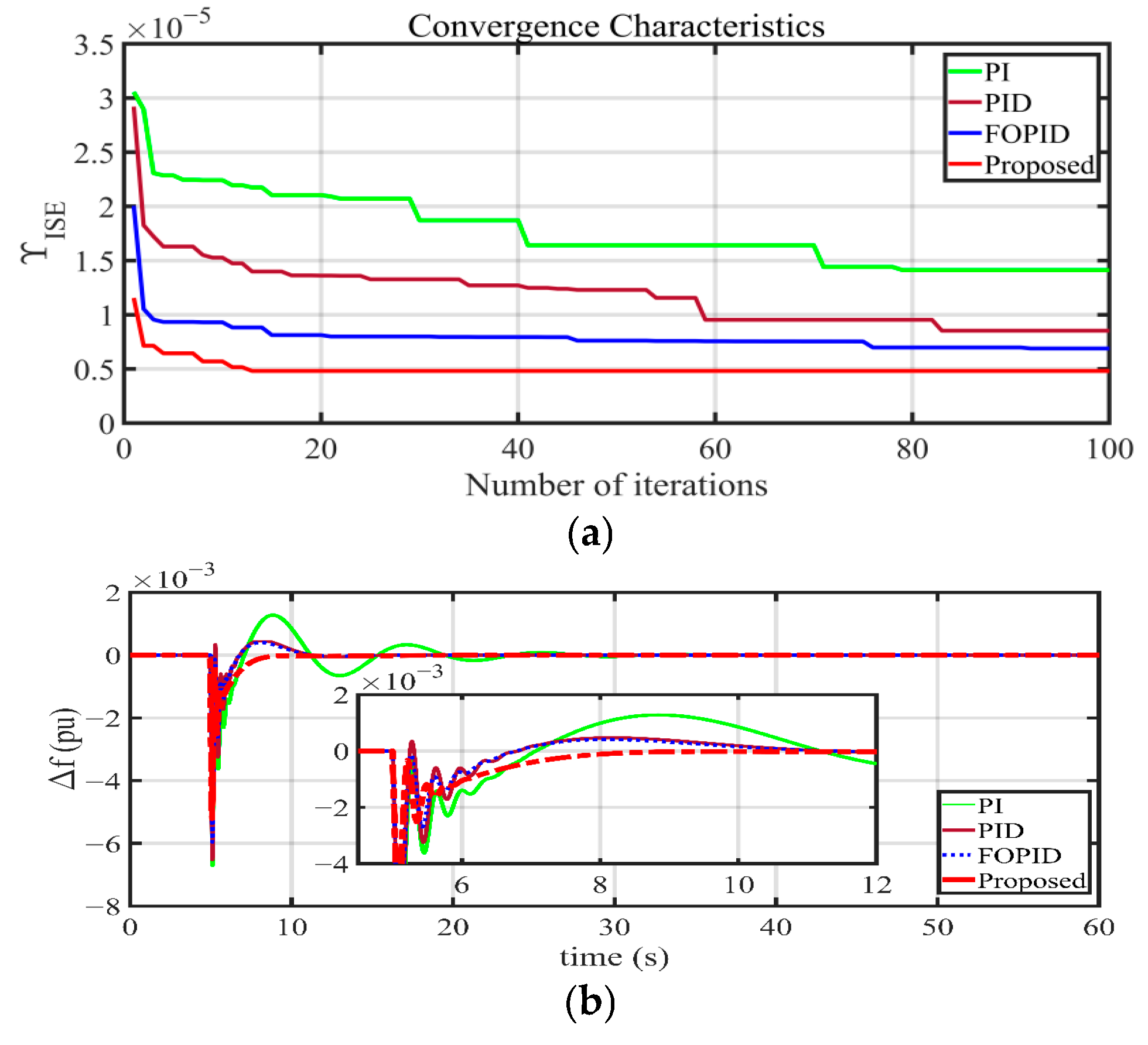
A detailed comparative analysis considering all the performance metrics, i.e., ISE, ITSE, IAE, and ITAE (presented in Section 2.2, Equations (14)–(17)), is presented in Table 2 with different control topologies tuned by the FLO algorithm. The best values of the different objective functions chosen after running the FLO algorithm multiple times are noted in Table 2. From Table 2, it is observed that the minimum objective function value is achieved with the ISE objective function, and a comparison of the convergence characteristics is shown in Figure 3a. According to the convergence characteristics, it can be stated that the proposed PIDA controller tuned by the FLO technique has achieved better performance compared to the other considered control techniques, indicating a fast convergence criterion. Therefore, this result establishes the superiority of the proposed FLO-based PIDA controller over the others. Furthermore, a performance assessment utilising the frequency deviation responses is presented in Figure 3b. According to the obtained dynamic responses, it can be confirmed that superior performance is achieved by the proposed FLO-optimised PIDA controller. The dynamic response of the proposed controller shows a tendency to reach the steady-state value faster compared to the other considered techniques. Therefore, the performance of the system can be validated with the help of the results presented in Table 3. In further subsections, the system performance evaluation is carried out considering different RLD conditions.

3.2. System Performance Analysis Considering RLD and Variations in the Power Output of SPGU and WPGU

Further, the system performance assessment is carried out considering an RLD scenario. In this subsection, the evaluation is performed considering two different RLD signals. In the first stage, a step-wise variable RLD (SRLD) signal is considered, and in the next stage, a Sinusoidal RLD (SiRLD) signal is implemented. Additionally, to enhance the complexity of performance assessment, variations in the output power of the SPGU and WPGU systems are considered, assuming a realistic power system scenario. A detailed performance assessment is presented in the following subsections.

3.2.1. Step-Wise Random Load Disturbance (SRLD) Condition and Varying SPGU and WPGU Power

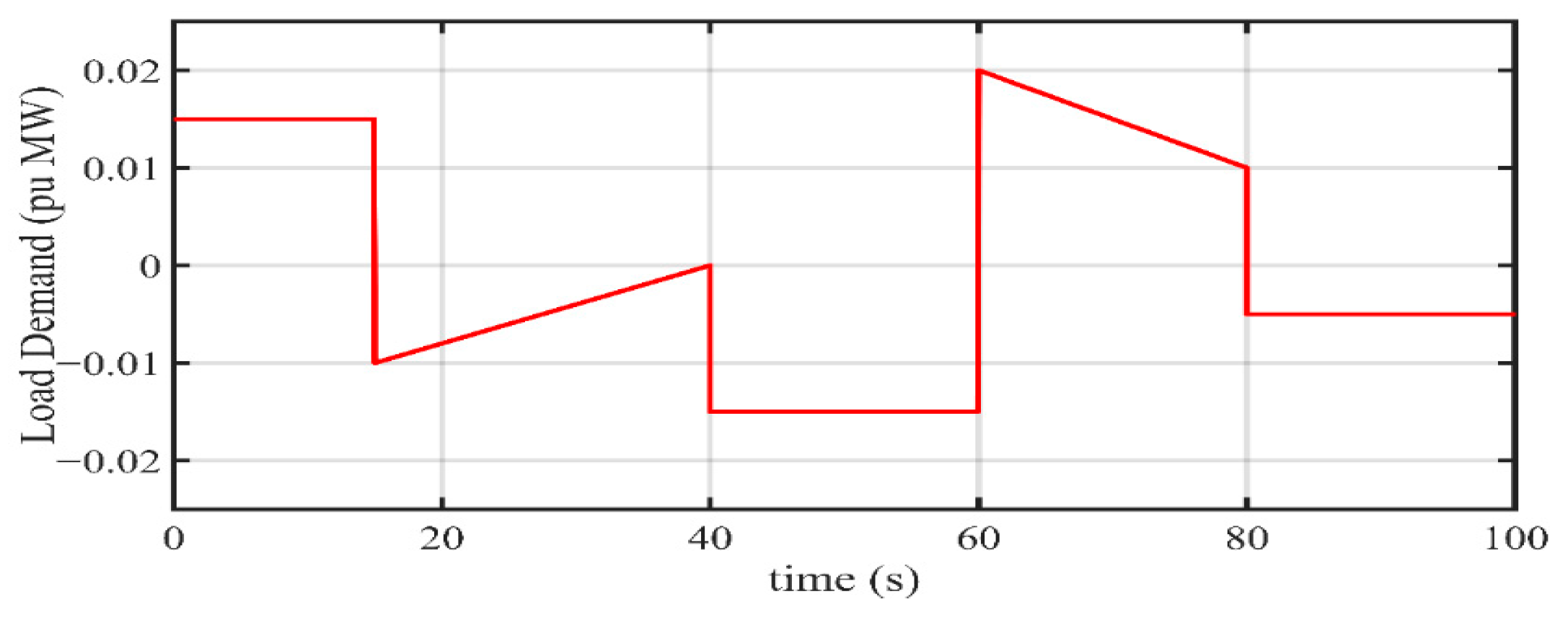
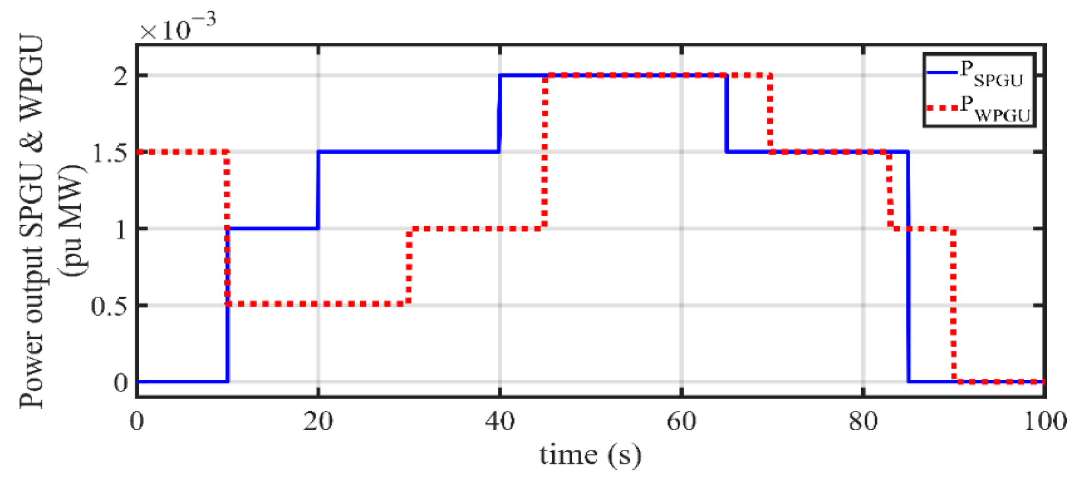
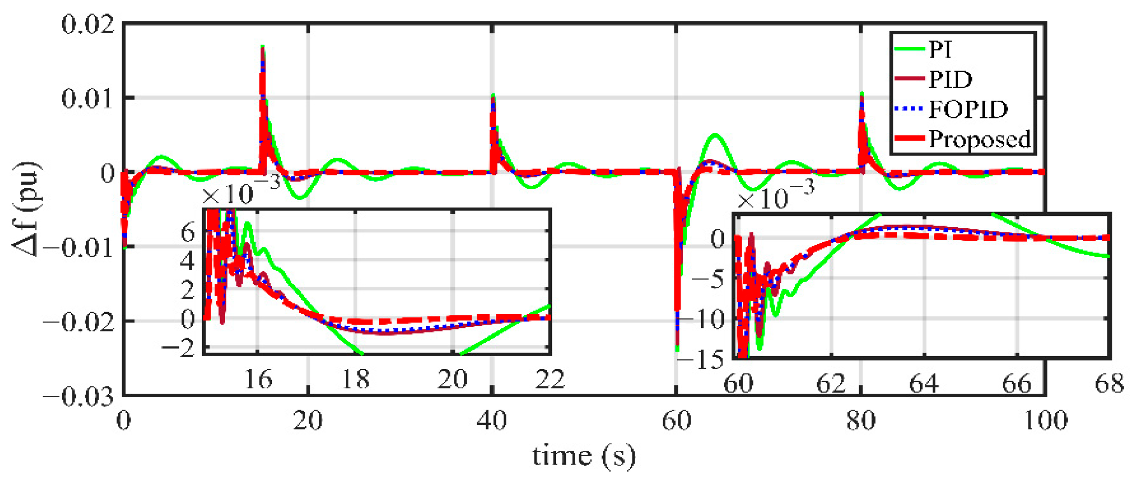
In the case of a practical scenario, a system needs to handle various parameter uncertainties. Therefore, in this subsection, the system performance evaluation is carried out considering variations in load demands and the power output deviations of SPGU and WPGU systems. In this case, the SRLD is considered as the test load demand signal. It should be mentioned that the gain parameters of the proposed controller are not altered for this case study. In Figure 4, variations in load demand and in Figure 5 variations considered in the output power of SPGU and WPGU are shown, respectively. Further, the system frequency deviation response is shown in Figure 6. Detailed simulation results indicate the superiority of the proposed FLO-based PIDA controller compared to the other considered control schemes. The best system frequency response in terms of overshoots, undershoots, oscillations, and settling time is obtained in the presence of the proposed control topology. Additionally, the frequency response has shown a tendency to settle quickly to the desired zero steady-state condition under the influence of the proposed control topology. Therefore, the proposed controller can be confirmed as the best choice under the conditions of random load disturbances and uncertainties associated with solar- and wind-power-generating units.

3.2.2. Sinusoidal Random Loading Disturbance (SiRLD) and Varying SPGU and WPGU Power

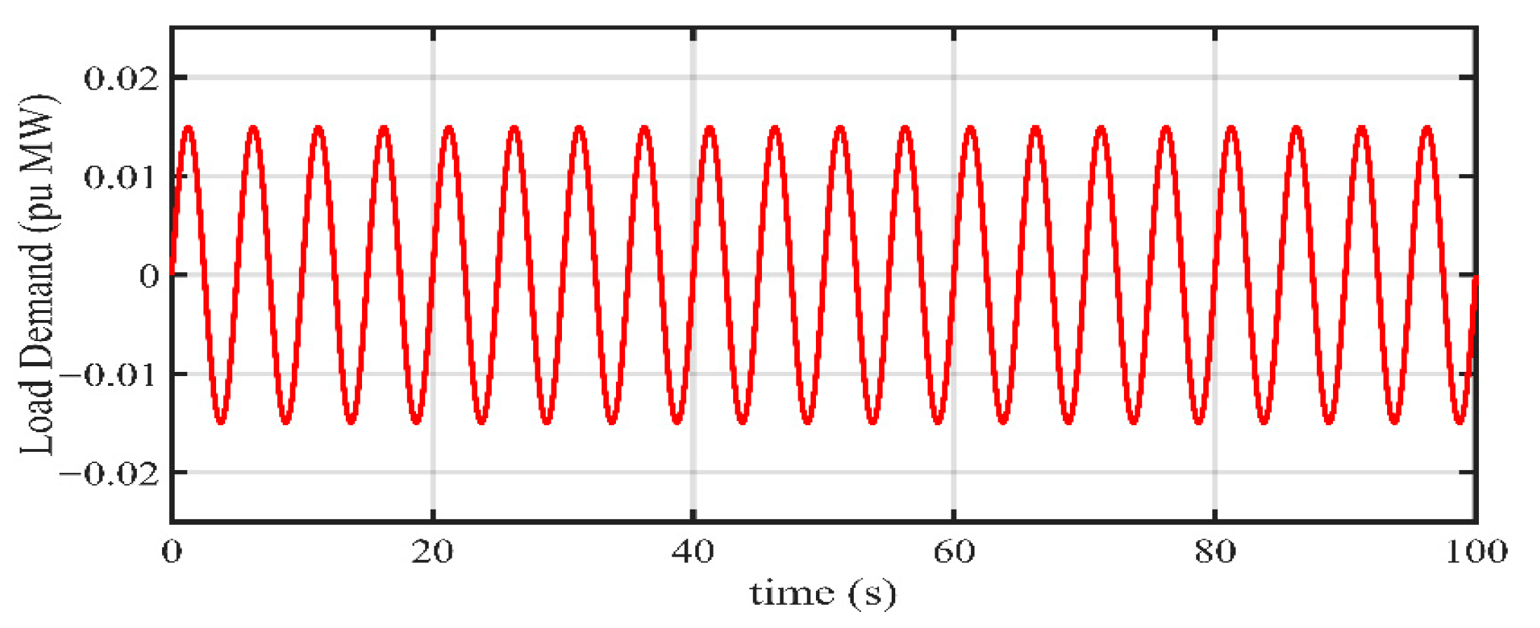
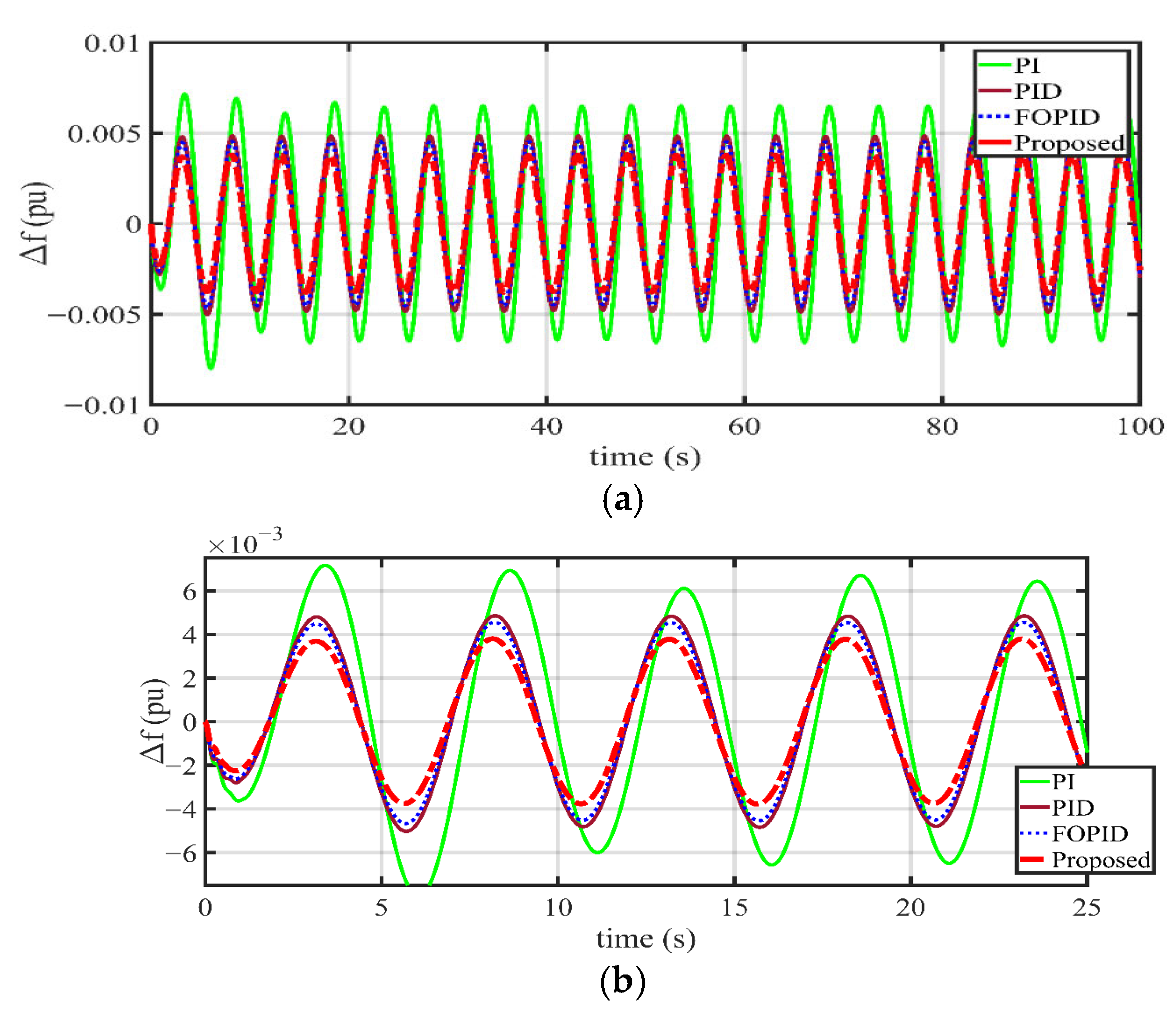
In this subsection, the variations in the output power of the SPGU and WPGU are considered to be the same as in Section 3.2.1. However, the load demand signal is considered to be different than the previous test case scenario. In this case, the SiRLD condition has been implemented as the load demand variation. The applied SiRLD signal is presented in Figure 7. Further, the frequency deviation response is presented in Figure 8. Additionally, the magnified response of the frequency response signal is shown in Figure 8b for better understanding. According to the obtained results, it can be established that the overall response of the islanded microgrid scenario considering the proposed FLO-tuned PIDA controller is showing superior performance compared to the other available techniques. It is also observed that the overall frequency deviation appears to be minimum, which is less than 1% of the rated frequency in the case of the proposed control topology. Therefore, these dynamic responses ensure the improved efficacy of the proposed controller to achieve the desired performance of the considered power system.

3.3. Performance Assessment Considering Stochastic Load Demand and Fluctuating Power Output of WPGU

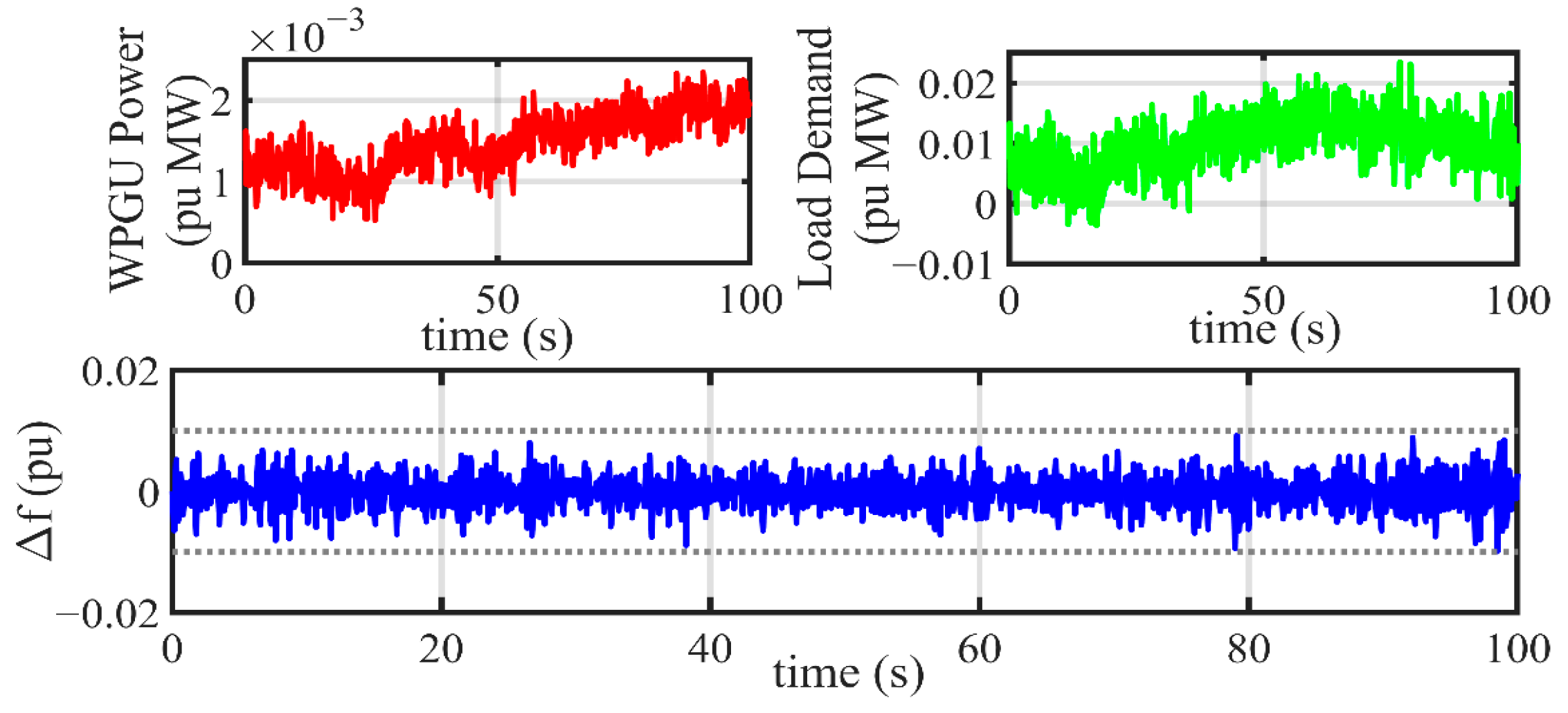
This subsection presents the performance assessment of the suggested power system considering the stochastic nature of the load demand and the power generation intermittency of the WPGU. The output power of the SPGU is considered to be the same as in Section 3.2.1. The stochastic WPGU model, as well as the load demands model, is adopted from [42,43,44], and their generalised diagrams are presented in Figure 9 and Figure 10, respectively. The parameters of the stochastic model of the WPGU are the same as those considered in Section 2.1.2, and kN and kL are random values within the range of [0.1, 1]. The stochastic nature of the signal is generated considering the noise signals, low-pass filters, and high-pass filters. In Figure 10, PL indicates the nominal load demand in per unit, and the limiter is used so that the output power does not vary more than ±2% of the load demand. The detailed dynamic responses of the WPGU output power, load demand, and frequency deviations are shown in Figure 11. From Figure 11, it can be stated that under the uncertain power generation and stochastic load demand, the frequency fluctuations are within the limits and limited to below 1% of the rated frequency value. Therefore, the considered islanded microgrid scenario achieves the desired frequency responses with the proposed controller. In order to check the robustness of the proposed controller in this scenario, the controller gain parameters are not optimised. The obtained results validate the effectiveness of the proposed PIDA controller under the considered test scenario.

3.4. Comparative Analysis Considering Recently Utilised Control Topologies with the Proposed FLO-Tuned PIDA Controller

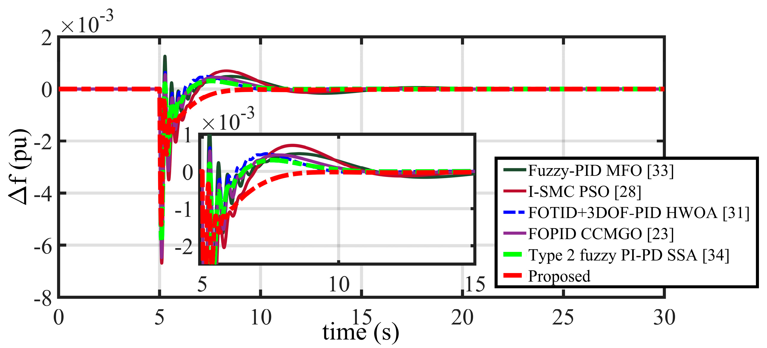
The performance assessment is extended further considering a comparative analysis between the recently suggested control topologies and the proposed FLO-tuned PIDA controller. In this regard, for the detailed comparison, an MFO-based fuzzy-PID controller [33], a PSO-tuned integral-based sliding mode control (I-SMC) [28], an HWOA-tuned cascade fractional order hybrid controller combining FOTID and 3DOF-PID [31], a CCMGO-based fractional-order PID (FOPID) controller [23], an SSA-optimised cascade double-input interval type 2 fuzzy logic controller with a PI–PD controller [34], and the proposed FLO-tuned PIDA controllers are chosen. For comparing the different control strategies in a fair and unbiased environment, all the optimisation tests are performed considering the same criteria, i.e., same computational arrangement, same initial conditions, and same number of iterations. The operational assessment comparison adopting different performance indices are presented in Table 4. It can be observed that the ISE technique has achieved the minimum objective function. Therefore, the ISE performance index is selected further to design the controller configuration. Accordingly, all the results are presented in Figure 12 and Table 5 considering only the ISE technique. The detailed dynamic responses of the frequency deviation are depicted in Figure 12, followed by Table 5, which summarises the various frequency responses of the different adopted control schemes. Based on the depicted dynamic responses as well as tabular representation, the superiority of the proposed FLO-tuned PIDA controller can be confirmed. Furthermore, the magnified response also assures that under the performance of the proposed control scheme, the frequency response reaches the steady state region very quickly as compared to the other considered controllers. Therefore, it can be concluded that the proposed PIDA controller ensures significant performance enhancement of in the presence of the islanded microgrid scenario as compared to the other considered controllers.

3.5. Performance Validation Considering a 33-Bus Radial Distribution Network

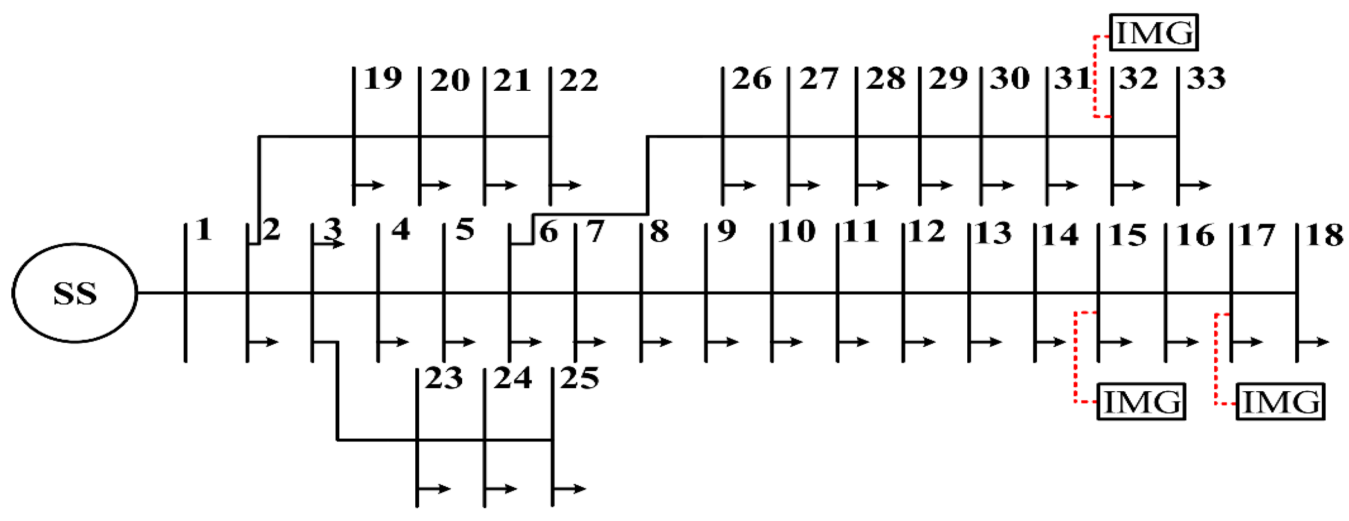
Finally, the performance assessment is carried out considering two conditions in a 33-bus radial distribution network [41]. In the first case, the distribution load flow analysis of the distribution system is performed without integrating the proposed microgrid (presented as the IMG) unit. In the next scenario, distribution load flow is performed integrating the IMG units, which are connected at bus numbers 15, 17, and 32, as shown in Figure 13. In order to investigate the performance of the radial distribution network in this scenario, the integration of the proposed microgrid model is carried out, where the voltage limits are generally lower [41]. Further, the variations in the reactive power at the buses are kept constant, as in this problem the system power–frequency balance is the main point of concern. In order to simulate this test scenario, the parameters of generating units as well as load disturbances are taken as similar to Section 3.1. By considering the distribution load flow analysis under two different network configurations, a comparative analysis considering the bus voltage magnitudes is depicted in Figure 14, and the overall network power loss profile is presented in Table 6. According to this comparative analysis (shown in Figure 14 and Table 6), it can be established that with the inclusion of the proposed microgrid model, the performance of the considered radial distribution network is improved significantly in terms of voltage magnitude and the overall network power loss reduction. In the conventional operation, the overall power loss is 202.66 kW, whereas after inclusion of the proposed islanded microgrid model, the network power loss reduces to 166.15 kW. Practically, the reduction in power loss seems to be very little, but in the case of large-scale networks, the proposed power system can attenuate the power loss to a larger extent. Therefore, this suggested islanded microgrid is capable of improving the overall performance of various power system networks.

4. Conclusions

This paper proposes a Fick’s law optimisation algorithm-based PIDA controller for performance improvement of an islanded microgrid integrated with renewable energy resources under disturbance conditions. The microgrid system is configured with various generating sources like SPGUs, WPGUs, and DGUs and with different ESUs. Numerous performance assessments of the proposed control topology under the suggested power system considering the various operating scenarios like different loading conditions and parameter uncertainty were carried out. In this connection, comprehensive investigations were performed considering the MATLAB 2017b Simulink environment. Additionally, comparative performance analyses between popular control topologies and the proposed FLO-based PIDA control scheme are presented. The performance of the proposed microgrid configuration was further investigated on a 33-bus radial distribution network. Based on the obtained results, it can be concluded that the proposed controller showcased its superior performance compared to other available control schemes in all test case investigations. A significant improvement in the system performance in terms of frequency deviation undershoots, overshoots, oscillations, and settling time has been achieved with the proposed controller. The system response with considerably low frequency fluctuation is achieved even under load perturbations and uncertainties associated with REPP. Finally, it can be stated that the proposed FLO-based PIDA controller is quite superior to the existing control techniques for minimising the frequency deviations of an islanded microgrid under diverse AGC operating conditions.

Author Contributions

Conceptualisation, P.S., S.G., and D.D.; methodology, P.S., S.G., and D.D.; software, P.S. and S.G.; validation, S.R.G., A.A., and D.D.; formal analysis, P.S., S.G., S.R.G., and M.B.B.; investigation, P.S., S.G., S.R.G., and A.A.; resources, P.S., S.G., and D.D.; writing—original draft preparation, P.S., S.G., and D.D.; writing—review and editing, P.S., S.G., S.R.G., and M.B.B.; supervision, S.R.G., A.A., and D.D. All authors have read and agreed to the published version of the manuscript.

Funding

This research received no external funding.

Data Availability Statement

The data related to contributions of the authors in this study are included in the article. Please contact the corresponding author for any further data requirements.

Conflicts of Interest

The authors declare no conflicts of interest.

Abbreviations

The following abbreviations are used in this manuscript:
REPPRenewable-energy-based power producers
TPPTraditional power producers
TPGUThermal-power-generating unit
HPGUHydro-power generating unit
NTPPNon-traditional power producer
SPGUSolar-power-generating unit
WPGUWind-power-generating unit
TETidal energy
GTEGeothermal energy
DGSDiesel generator system
ESUEnergy storage unit
AGCAutomatic generation control
AEAqua electrolyser
FCUFuel cell unit
PGUPower-generating units
PFCPrimary frequency control
SFCSecondary frequency control
DGUDiesel engine generating unit
MTUMicroturbine units
FESUFlywheel ESUs
BESUBattery ESUs
UCUltra capacitors
RFBRedox-flow battery
VICVirtual inertia control
LQGConventional linear quadratic gaussian
LQIModified LQG with linear quadratic integral
PIDProportional integral derivative
FOPIDFractional order PID
I-SMCIntegral-based sliding mode control
FO-FPPDPIFractional order fuzzy pre-compensated PDPI
1 + PIFuzzy PIDF
DOBCDisturbance-observer-based control
MPCModel predictive control
AIArtificial intelligence
COCheetah optimiser
CF-GSAImproved centripetal force-gravity search algorithm
i-SCAImproved sine cosine algorithm
SSASquirrel search algorithm
CCMGOChaotic chimp-mountain gazelle optimiser
QOHSQuasi-oppositional harmony search
MFOMoth-flame optimisation
TLBOTeaching learning based optimisation
PSOParticle swarm optimisation
HWOAHybrid whale optimisation algorithm
MSSAMulti-objective salp swarm algorithm
SSASalp swarm algorithm
GAGenetic algorithm
DEDifferential evolution
FLOFick’s law optimisation
PIDAProportional–integral–derivative–acceleration
EVUElectric vehicle unit
V2GVehicle-to-grid
SLDStep load disturbance
GINGrid-integrating network
RPGURenewable PGU
SRLDStep-wise random load disturbance
SiRLDSinusoidal random loading disturbance
RLDRandom load disturbances
Os/UsPeak value of over/undershoot
STSettling time
ϕ Solar   irradiation   ( in   W / m 2 )
TmAmbient temperature (°C)
η Efficiency of a solar unit
Ac Effective   cross - sec tional   area   ( in   m 2 )
KPVGain of solar unit transfer function
TPVTime constant of solar module
TGINTime constant of grid integration unit
ρ w v Air   density   ( in   kg / m 2 )
RWPRadius of the turbine blade(in m)
γ Tip speed ratio
δ Blade pitch angle (in degrees)
CWPPower coefficient
VSVelocity of wind (in km/h)
KWTGain of wind generator transfer function
TWTTime constant of the wind generator unit
TDGUTime constant of the diesel generator unit
KDGain of the DGU-related delay unit
TDTime constant of the DGU-related delay unit
KBMUGain of battery energy storage unit
TBMUTime constant of battery storage transfer function
KFWGain of battery flywheel storage unit
TBWTime constant of the flywheel storage transfer function
KEVUGain of EVU
TBCUTime constant of EV battery unit
PGGenerated power
PLPower demand
KIMGGain of the generator–load mismatch transfer function
TIMGTime constant of the generator–load mismatch unit
ISEIntegral square error
ITSEIntegral time square error
IAEIntegral absolute error
ITAEIntegral time absolute error
C(s) Transfer function of PIDA controller
k P ,   k I
k D ,   k a
PIDA controller gain parameters
DFDiffusion level
EQEquilibrium level
SSSteady state
SPopulation size in the search space
ASample population set
TTotal number of iterations
tPresent iteration
n k t Samples transferred from one stage to another
T f t Pre-determined threshold value
P1, P2Levels
n P 1 Number of samples present in level P1
n R D F Left-out samples in the DF stage
n E Q , P 2 t Equilibrium position in P2
D f P 1 , P 2 t Direction factor
FDirection of flow
ϕ P 1 , P 2 t Diffusion factor
eEffective emissivity
d C P 1 , P 2 t d g P 1 , P 2 t Concentration gradient
n E Q , P 1 t Equilibrium position in P1
u, lUpper and lower boundaries of the search space
Q E Q t Relative quality of P2
S E Q t Motion step of the samples in the DF stage
F F E Q t Best fitness factor in P2 level
F F T D F t Computed fitness factor
n S S t Steady state location
S S S t Motion step of samples in the SS stage
Q S S t Relative quality of perspective medium

Appendix A

Table A1. Parameters of the islanded microgrid system.
System Parameters, Optimisation Parameters, and Controller Gains
PR = 10 MWKD = 1KBMS = 1
KPV = 1TD = 2 sTBMS = 0.01 s
TPV = 1.5 sTDGU = 1 sKFW = 1
KWT = 1KEVU = 1TFW = 0.01 s
TWT = 1.8 sRDGU = 1 Hz/pu MWKIMG = 70.6
TGIN = 0.001 sTBCU = 0.01 sTIMG = 7.06 s
Δ P SPGU ( Max ) = 0.003 pu Δ P SPGU ( Min ) = 0.0 pu Δ P WPGU ( Max ) = 0.003 pu
Δ P WPGU ( Min ) = 0.0 pu Δ P DGU ( Max ) = 0.003 pu Δ P DGU ( Min ) = 0.0 pu
Δ P EVU ( Max ) = 0.002 pu Δ P EVU ( Min ) = −0.002 pu Δ P BESU ( Max ) = 0.001 pu
Δ P BESU ( Min ) = −0.001 pu Δ P FESU ( Max ) = 0.001 pu Δ P FESU ( Min ) = −0.001 pu
Population size = 100Dimension = 4Number of iterations = 100
kP = 5.23kI = 2.37   kD = 3.85   ka = 0.75

References

  1. Mokhtar, M.; Marei, M.I.; Sameh, M.A.; Attia, M.A. An Adaptive Load Frequency Control for Power Systems with Renewable Energy Sources. Energies 2022, 15, 573. [Google Scholar] [CrossRef]
  2. Ullah, K.; Ullah, Z.; Aslam, S.; Salam, M.S.; Salahuddin, M.A.; Umer, M.F.; Humayon, M.; Shaheer, H. Wind Farms and Flexible Loads Contribution in Automatic Generation Control: An Extensive Review and Simulation. Energies 2023, 16, 5498. [Google Scholar] [CrossRef]
  3. Peddakapu, K.; Mohamed, M.R.; Srinivasarao, P.; Arya, Y.; Leung, P.K.; Kishore, D.J.K. A State-of-the-Art Review on Modern and Future Developments of AGC/LFC of Conventional and Renewable Energy-Based Power Systems. Renew. Energy Focus 2022, 43, 146–171. [Google Scholar] [CrossRef]
  4. Gulzar, M.M.; Iqbal, M.; Shahzad, S.; Muqeet, H.A.; Shahzad, M.; Hussain, M.M. Load Frequency Control (LFC) Strategies in Renewable Energy-Based Hybrid Power Systems: A Review. Energies 2022, 15, 3488. [Google Scholar] [CrossRef]
  5. Li, Z.; Cheng, Z.; Liang, J.; Si, J. Distributed Cooperative AGC Method for New Power System With Heterogeneous Frequency Regulation Resources. IEEE Trans. Power Syst. 2023, 38, 4928–4939. [Google Scholar] [CrossRef]
  6. Huang, T.; Wu, D.; Ilić, M. Cyber-Resilient Automatic Generation Control for Systems of AC Microgrids. IEEE Trans. Smart Grid 2024, 15, 886–898. [Google Scholar] [CrossRef]
  7. Sahu, P.C.; Mohapatra, S.; Bhatta, S.K.; Tejani, G.G.; Mousavirad, S.J. An Exclusive Survey on Robust Controllers and Novel Optimization Techniques for AGC of Power System. Energy Rep. 2025, 13, 3845–3868. [Google Scholar] [CrossRef]
  8. Sahu, P.C. Impact and Integration of Electric Vehicles on Renewable Energy Based Microgrid: Frequency Profile Improvement by a-SCA Optimized FO-Fuzzy PSS Approach. Green Energy Intell. Transp. 2025, 4, 100191. [Google Scholar] [CrossRef]
  9. Khosravi, N. Finite-Time Control Scheme for Effective Voltage and Frequency Regulation in Networked Microgrids. Int. J. Electr. Power Energy Syst. 2025, 165, 110481. [Google Scholar] [CrossRef]
  10. Rai, A.; Das, D.K. The Development of a Fuzzy Tilt Integral Derivative Controller Based on the Sailfish Optimizer to Solve Load Frequency Control in a Microgrid, Incorporating Energy Storage Systems. J. Energy Storage 2022, 48, 103887. [Google Scholar] [CrossRef]
  11. Hafez, W.A.; Aly, M.; Mohamed, E.A.; Nagem, N.A. Improved Fractional Order Control with Virtual Inertia Provision Methodology for Electric Vehicle Batteries in Modern Multi-Microgrid Energy Systems. J. Energy Storage 2025, 106, 114582. [Google Scholar] [CrossRef]
  12. Tah, A.; Das, D. Operation of Small Hybrid Autonomous Power Generation System in Isolated, Interconnected and Grid Connected Modes. Sustain. Energy Technol. Assess. 2016, 17, 11–25. [Google Scholar] [CrossRef]
  13. Shirali, S.; Zolfaghari Moghaddam, S.; Aliasghary, M. An Interval Type-2 Fuzzy Fractional-Order PD-PI Controller for Frequency Stabilization of Islanded Microgrids Optimized with CO Algorithm. Int. J. Electr. Power Energy Syst. 2025, 164, 110422. [Google Scholar] [CrossRef]
  14. Taha, M.Q.; Kurnaz, S. Droop Control Optimization for Improved Power Sharing in AC Islanded Microgrids Based on Centripetal Force Gravity Search Algorithm. Energies 2023, 16, 7953. [Google Scholar] [CrossRef]
  15. Liu, X.; Liu, Z.-W.; Chi, M.; Wei, G. Frequency Control for Islanded AC Microgrid Based on Deep Reinforcement Learning. Cyber-Phys. Syst. 2024, 10, 43–59. [Google Scholar] [CrossRef]
  16. Mohan, A.M.; Meskin, N.; Mehrjerdi, H. LQG-Based Virtual Inertial Control of Islanded Microgrid Load Frequency Control and DoS Attack Vulnerability Analysis. IEEE Access 2023, 11, 42160–42179. [Google Scholar] [CrossRef]
  17. Yildirim, B.; Gheisarnejad, M.; Mohammadzadeh, A.; Khooban, M.H. Intelligent Frequency Stabilization of Low-Inertia Islanded Power Grids-Based Redox Battery. J. Energy Storage 2023, 71, 108190. [Google Scholar] [CrossRef]
  18. Sanki, P.; Basu, M.; Pal, P.S.; Das, D.; Gupta, S. Design of an Improved Tie-Line Power Model for a PEV Based Interconnected Microgrid Under AGC Operation. In Proceedings of the 2022 IEEE VLSI Device Circuit and System (VLSI DCS), Kolkata, India, 26–27 February 2022; pp. 154–159. [Google Scholar]
  19. Wu, M.; Ma, D.; Xiong, K.; Yuan, L. Optimizing Load Frequency Control in Isolated Island City Microgrids: A Deep Graph Reinforcement Learning Approach with Data Enhancement across Extensive Scenarios. Front. Energy Res. 2025, 12, 1384995. [Google Scholar] [CrossRef]
  20. Sahu, P.C.; Prusty, R.C.; Panda, S. Optimal Design of a Robust FO-Multistage Controller for the Frequency Awareness of an Islanded AC Microgrid under i-SCA Algorithm. Int. J. Ambient Energy 2022, 43, 2681–2693. [Google Scholar] [CrossRef]
  21. He, P.; Huang, X.; He, R.; Yuan, L. Load Frequency Control in Isolated Island City Microgrids Using Deep Graph Reinforcement Learning Considering Extensive Scenarios. AIP Adv. 2025, 15, 015316. [Google Scholar] [CrossRef]
  22. Oshnoei, S.; Aghamohammadi, M.; Oshnoei, S.; Oshnoei, A.; Mohammadi-Ivatloo, B. Provision of Frequency Stability of an Islanded Microgrid Using a Novel Virtual Inertia Control and a Fractional Order Cascade Controller. Energies 2021, 14, 4152. [Google Scholar] [CrossRef]
  23. Shiva, C.K.; Sen, S.; Basetti, V.; Reddy, C.S. Forward-Thinking Frequency Management in Islanded Marine Microgrid Utilizing Heterogeneous Source of Generation and Nonlinear Control Assisted by Energy Storage Integration. Sci. Rep. 2025, 15, 13794. [Google Scholar] [CrossRef] [PubMed]
  24. Oshnoei, S.; Aghamohammadi, M.R.; Oshnoei, S.; Sahoo, S.; Fathollahi, A.; Khooban, M.H. A Novel Virtual Inertia Control Strategy for Frequency Regulation of Islanded Microgrid Using Two-Layer Multiple Model Predictive Control. Appl. Energy 2023, 343, 121233. [Google Scholar] [CrossRef]
  25. Shiva, C.K.; Vedik, B.; Mahapatra, S.; Nandi, M.; Raj, S.; Mukherjee, V. Load Frequency Stabilization of Stand-Alone Hybrid Distributed Generation System Using QOHS Algorithm. Int. J. Numer. Model. Electron. Netw. Devices Fields 2022, 35, e2998. [Google Scholar] [CrossRef]
  26. Raju, G.V.; Srikanth, N.V. Frequency Control of an Islanded Microgrid with Multi-Stage PID Control Approach Using Moth-Flame Optimization Algorithm. Electr. Eng. 2025, 107, 8861–8878. [Google Scholar] [CrossRef]
  27. Suman, G.K.; Yadav, S.; Guerrero, J.M. Frequency Regulation Strategy in Islanded Microgrid With High Renewable Penetration Supported by Virtual Inertia. Smart Grids Energy 2024, 9, 33. [Google Scholar] [CrossRef]
  28. Aggarwal, N.; Mahajan, A.N.; Nagpal, N. Optimized Sliding Mode Control for Improved Frequency Response in an Islanded Microgrid System. Aust. J. Electr. Electron. Eng. 2025, 22, 297–315. [Google Scholar] [CrossRef]
  29. Mohanty, D.; Panda, S. Multi-Objective Salp Swarm Algorithm-Based Fractional Order Fuzzy Precompensated PDPI Controller for Frequency Regulation of Hybrid Power System. Int. J. Numer. Model. Electron. Netw. Devices Fields 2023, 36, e3094. [Google Scholar] [CrossRef]
  30. Sahu, J.; Satapathy, P.; Sahu, B.K.; Mohanty, P.K.; Naik, A.K. Design of a Quasi-Oppositional FBI Based Fuzzy PIDF (1 + PI) Controller for Frequency Regulation with Renewable Energy Sources and Energy Storage Elements. Int. J. Numer. Model. Electron. Netw. Devices Fields 2023, 36, e3120. [Google Scholar] [CrossRef]
  31. Mondal, B.; Biswas, S.; Roy, P.K.; Dutta, S. Hybrid Whale Optimization Algorithm-Scaled Cascade Fractional Order Hybrid Controller Applied to Renewable Based Electric Vehicle Generating Systems. Int. J. Numer. Model. Electron. Netw. Devices Fields 2024, 37, e3144. [Google Scholar] [CrossRef]
  32. Aggarwal, N.; Mahajan, A.N.; Nagpal, N. Frequency Control Enhancement of an Islanded Microgrid Using Disturbance-Observer-Based Approach. Int. J. Electron. 2025, 112, 496–517. [Google Scholar] [CrossRef]
  33. Sanki, P.; Mazumder, S.; Basu, M.; Pal, P.S.; Das, D. Moth Flame Optimization Based Fuzzy-PID Controller for Power–Frequency Balance of an Islanded Microgrid. J. Inst. Eng. India Ser. B 2021, 102, 997–1006. [Google Scholar] [CrossRef]
  34. Yıldız, S.; Gunduz, H.; Yildirim, B.; Temel Özdemir, M. An Islanded Microgrid Energy System with an Innovative Frequency Controller Integrating Hydrogen-Fuel Cell. Fuel 2022, 326, 125005. [Google Scholar] [CrossRef]
  35. Tudu, A.K.; Naguru, N.; Dey, S.H.N.; Paul, S. Load Frequency Control of an Isolated Microgrid Using Optimized Model Predictive Control by GA. Electr. Eng. 2024, 106, 4171–4183. [Google Scholar] [CrossRef]
  36. Li, J.; Cheng, Y. Deep Meta-Reinforcement Learning-Based Data-Driven Active Fault Tolerance Load Frequency Control for Islanded Microgrids Considering Internet of Things. IEEE Internet Things J. 2024, 11, 10295–10303. [Google Scholar] [CrossRef]
  37. Li, J.; Zhou, T.; Keke, H.; Yu, H.; Du, H.; Liu, S.; Cui, H. Distributed Quantum Multiagent Deep Meta Reinforcement Learning for Area Autonomy Energy Management of a Multiarea Microgrid. Appl. Energy 2023, 343, 121181. [Google Scholar] [CrossRef]
  38. Realization of Robust Frequency Stability in Low-Inertia Islanded Microgrids with Optimized Virtual Inertia Control|IEEE Journals & Magazine|IEEE Xplore. Available online: https://ieeexplore.ieee.org/document/10506525 (accessed on 10 September 2025).
  39. Hashim, F.A.; Mostafa, R.R.; Hussien, A.G.; Mirjalili, S.; Sallam, K.M. Fick’s Law Algorithm: A Physical Law-Based Algorithm for Numerical Optimization. Knowl.-Based Syst. 2023, 260, 110146. [Google Scholar] [CrossRef]
  40. Messini, E.; Bourek, Y.; Ammari, C.; Pesyridis, A. The integration of solar-hydrogen hybrid renewable energy systems in oil and gas industries for energy efficiency: Optimal sizing using Fick’s Law optimisation Algorithm. Energy Convers. Manag. 2024, 308, 118372. [Google Scholar] [CrossRef]
  41. Das, D.; Kothari, D.P.; Kalam, A. Simple and Efficient Method for Load Flow Solution of Radial Distribution Networks. Int. J. Electr. Power Energy Syst. 1995, 17, 335–346. [Google Scholar] [CrossRef]
  42. Li, X.; Hui, D.; Lai, X.; Yan, T.; Li, X.; Hui, D.; Lai, X.; Yan, T. Power Quality Control in Wind/Fuel Cell/Battery/Hydrogen Electrolyzer Hybrid Micro-Grid Power System. In Applications and Experiences of Quality Control; IntechOpen: London, UK, 2011; ISBN 978-953-307-236-4. [Google Scholar]
  43. Magdy, G.; Mohamed, E.A.; Shabib, G.; Elbaset, A.A.; Mitani, Y. SMES Based a New PID Controller for Frequency Stability of a Real Hybrid Power System Considering High Wind Power Penetration. IET Renew. Power Gener. 2018, 12, 1304–1313. [Google Scholar] [CrossRef]
  44. Gupta, S.; Mukhopadhyay, S.; Banerji, A.; Sanki, P.; Biswas, S.K. Student psychology-based optimization tuned pida controller for improved frequency regulation of a two-area microgrid. Arab. J. Sci. Eng. 2025, 50, 5487–5508. [Google Scholar] [CrossRef]
Figure 1. Schematic diagram of the adopted single-area microgrid scenario.
Inventions 10 00099 g001
Figure 2. (a) Pole-zero plot varying kp ∊ [0.01, 20], (b) pole-zero plot varying ki ∊ [0.01, 20], (c) pole-zero plot varying kd ∊ [0.01, 20], and (d) pole-zero plot varying ka ∊ [0.01, 20].
Inventions 10 00099 g002aInventions 10 00099 g002b
Figure 3. (a) Convergence curve comparison between different controllers considering the best ϒ I S E (b) Dynamic response of the frequency deviation under 1% SLD.
Inventions 10 00099 g003
Figure 4. Step-wise load demand variation.
Inventions 10 00099 g004
Figure 5. Variations in the output power of the SPGU and WPGU.
Inventions 10 00099 g005
Figure 6. Dynamic response of the frequency deviation under SRLD.
Inventions 10 00099 g006
Figure 7. Random loading disturbance (SiRLD).
Inventions 10 00099 g007
Figure 8. (a) Dynamic response of the frequency deviation under SiRLD, (b) The magnified dynamic response of the frequency deviation under SiRLD.
Inventions 10 00099 g008
Figure 9. Stochastic WPGU model.
Inventions 10 00099 g009
Figure 10. Stochastic load demand model.
Inventions 10 00099 g010
Figure 11. Uncertain and stochastic variation in the output power of the WPGU and load demand; dynamic response of the frequency deviation under the uncertain and stochastic conditions.
Inventions 10 00099 g011
Figure 12. Dynamic response of the frequency deviation under 1% SLD considering a comparative analysis between recently adopted control schemes with the proposed controller.
Inventions 10 00099 g012
Figure 13. Modified 33-bus radial distribution network.
Inventions 10 00099 g013
Figure 14. Bus voltage comparison between before and after modifying the 33-bus radial distribution network.
Inventions 10 00099 g014
Table 1. Overview of the adopted case studies under different perturbations.
ScenarioComponent of Case StudiesSimulation Time (s)Disturbance Nature
1System performance analysis considering 1% SLD condition60Step load disturbance (SLD) condition
2System performance analysis considering RLD and variations in the power output of SPGU and WPGU100(a) Step-wise random load disturbance (SRLD) condition with power variations of SPGU and WPGU
100(b) Sinusoidal random loading disturbance (SiRLD) with power variations of SPGU and WPGU
3Performance assessment considering stochastic load demand and fluctuating power output of WPGU100Stochastic load demand and WPGU output power
4Comparative analysis considering recently utilised control topologies with the proposed FLO-tuned PIDA controller60SLD
5Performance validation considering a 33-bus radial distribution network60SLD
Table 2. Comparative analysis of the objective functions considering performance indices.
Controllers ϒ I S E ϒ I T S E ϒ I A E ϒ I T A E
PI14.12 × 10−69.86 × 10−50.01010.1091
PID8.53 × 10−63.98 × 10−50.00360.0249
FOPID6.89 × 10−63.21 × 10−50.00320.0216
Proposed4.81 × 10−62.61 × 10−50.00300.0198
Table 3. Comparison of the dynamic response of the system parameters under SLD condition.
ControllersSystem
Parameters
1% SLD Condition at 5 s.
Os × 10−4Us × 10−3ST (s)
PI Δ f 1 12.75−6.7126.16
PID Δ f 1 4.66−6.5214.52
FOPID Δ f 1 3.09−5.9112.27
Proposed Δ f 1 -−5.128.77
Table 4. Comparative analysis considering different objective functions under recently adopted control topologies.
Controllers ϒ I S E ϒ I T S E ϒ I A E ϒ I T A E
Fuzzy-PID MFO [33]9.53 × 10−65.38 × 10−50.00690.0355
I-SMC PSO [28]6.65 × 10−63.58 × 10−50.00620.0319
FOTID_3DOF-PID HWOA [31]6.03 × 10−63.51 × 10−40.00460.0289
FOPID-CCMGO [23]5.87 × 10−63.41 × 10−50.00410.0262
Type2 Fuzzy PI-PD SSA [34]5.23 × 10−62.99 × 10−50.00390.0221
Proposed4.81 × 10−62.61 × 10−50.00300.0198
Table 5. Comparison of the frequency deviation of the system parameters under different control topologies.
ControllersSystem
Parameters
1% SLD Condition at 5 s.
Os × 10−4Us × 10−3ST (s)
Fuzzy-PID MFO [33] Δ f 1 12.52−6.1818.86
I-SMC PSO [28] Δ f 1 -−6.6915.61
FOTID_3DOF-PID HWOA [31] Δ f 1 6.38−6.4510.93
FOPID-CCMGO [23] Δ f 1 5.46−6.4411.69
Type2 Fuzzy PI-PD SSA [34] Δ f 1 2.04−5.8612.59
Proposed Δ f 1 -−5.208.77
Table 6. Comparison of radial distribution network power loss.
Radial Distribution NetworkNetwork Loss
33-bus radial distribution network202.66 kW
Modified 33-bus radial distribution network(Proposed islanded microgrid connected at bus nos. 15, 17, 32)166.15 kW
Disclaimer/Publisher’s Note: The statements, opinions and data contained in all publications are solely those of the individual author(s) and contributor(s) and not of MDPI and/or the editor(s). MDPI and/or the editor(s) disclaim responsibility for any injury to people or property resulting from any ideas, methods, instructions or products referred to in the content.