Article

Addressing Development Challenges of the Emerging REEFS Wave Energy Converter

by
José P. P. G. Lopes de Almeida
* and
Vinícius G. Machado
MARE—Marine and Environmental Sciences Centre, Department of Civil Engineering, University of Coimbra, 3030-788 Coimbra, Portugal
*
Author to whom correspondence should be addressed.
Inventions 2025, 10(5), 85; https://doi.org/10.3390/inventions10050085
Submission received: 31 July 2025 / Revised: 12 September 2025 / Accepted: 21 September 2025 / Published: 26 September 2025

Abstract

This article addresses the multifaceted challenges inherent in the development of the novel REEFS (Renewable Electric Energy From Sea) wave energy converter (WEC). Building on the submerged pressure differential principle, it frames similar WECs before focusing on REEFS that combines renewable energy generation with coastal protection, functioning as an artificial reef. The review follows chronological criteria, encompassing experimental proof-of-concept, small-scale laboratory modeling, simplified and advanced computational fluid dynamics (CFD) simulations, and the design of a forthcoming real-sea model deployment. Key milestones include the validation of a passive variable porosity system, demonstration of wave-to-wire energy conversion, and quantification of wave attenuation for coastal defense. Additionally, the study introduces a second patent-protected REEFS configuration, isolating internal components from seawater via an elastic enveloping membrane. Challenges related to scaling, numerical modeling, and funding are thoroughly examined. The results highlight the importance of the proof-of-concept as the keystone of the development process, underscore the relevance of mixed laboratory-computational approaches and emphasize the need for a balanced equilibrium between intellectual property safeguard and scientific publishing. The REEFS development trajectory offers interesting insights for researchers and developers navigating the complex innovation seas of emerging wave energy technologies.

1. Introduction

The etymological root of the word “invention” lies in Latin, where it was associated with discovery or finding out [1]. Over time, the term acquired its current meaning, referring to the creation of something new that did not previously exist. However, to be meaningful, it must be linked to advancements and improvements. In this sense, an invention should result from a discovery—specifically, from finding out a better, non-obvious way of accomplishing something. The European Patent Convention (EPC) states that, for an invention to qualify for patent protection, it must be novel, have an inventive step and be industrially applicable [2].

1.1. Inventiveness for Untapping Wave Energy Potential

In the field of energy technologies, inventions play a pivotal role in tackling global sustainability challenges, especially when they are associated with the development and integration of renewable energy sources. Among these, ocean wave energy stands out as a highly promising and largely untapped source of renewable power. According to the World Energy Council [3] and Gunn & Stock-Williams [4], the total estimated world’s wave power is approximately 2 TW.
Wave energy’s intrinsic characteristics—including high energy intensity [5], greater predictability [6,7], and reduced visual and ecological impact [8]—make it an ideal candidate for integration into the global energy portfolio. Furthermore, with approximately 40% of the world’s population residing in coastal zones [9,10], the feasibility of nearshore and offshore energy deployment is bolstered by geographic and infrastructural factors.
This potential has driven a wave of technological advancements in wave energy converters (WECs), which are engineered to capture the hydraulic energy of ocean waves and transform it into usable electrical power.
The classification of WECs has progressed alongside technological developments, with traditional frameworks organizing devices according to four main criteria: (i) operating principle—such as oscillating water columns (OWCs), overtopping devices, and wave-activated bodies [11]; (ii) deployment location—categorized as shoreline, nearshore, or offshore (which may be floating, submerged, or bottom-mounted); (iii) directional alignment—including terminators, attenuators, and point absorbers; and (iv) Power Take-Off (PTO) system type—comprising mechanical, hydraulic, pneumatic, or direct electrical conversion methods [12]. More recent schemes incorporate additional operating principles types such as bulge waves, rotating mass systems, submerged pressure differential devices, and membrane-based converters [13,14,15,16], reflecting the inventive and rapidly diversifying nature of this field. Such diversification is further evidence of the invention process at work, as engineers seek ever-more efficient and site-adaptable designs.
The inventive proliferation within this sector is well-documented in patent databases. For instance, over the past decade, more than 1300 patents have been filed for just two technologies—OWCs and point absorbers [17]. These metrics demonstrate not only intense research activity but also a high degree of technological experimentation and intellectual property protection, reflecting both innovation and competition within the sector.
Despite this effort, wave energy technology is still considered immature when compared to wind and solar [18]. One key reason is the wide divergence in device architectures, which has impeded convergence on a standardized or dominant design [19]. To address this, frameworks such as the International Energy Agency–Ocean Energy Systems (IEA–OES) Technology Readiness Levels (TRLs) have been developed to track technological maturity in a structured manner [20].
In this evolving field, the REEFS (Renewable Electric Energy From Sea) WEC, examined in this article, represents one example. According to the TRL stages presented in [20] the current technological maturity of this concept can be estimated as TRL = 4. Submitted under patent EP3078844, granted in 2019, REEFS is a nearshore WEC based on the submerged pressure differential (SPD) principle [21].

1.2. The Submerged Pressure Differential Principle

There are several types of WEC projects, at different TRL stages, using the SPD principle. This type of WECs harnesses the pressure changes beneath passing waves to generate power, offering a low-visibility alternative to surface-based devices. By operating below the water, they avoid excessive wind and wave forces and minimize interference with maritime traffic. The text herein reviews some of the most relevant concepts.
Bombora’s mWave is an SPD WEC that converts wave motion into pneumatic energy using air-inflated membranes, which compress air through one-way valves to drive an axial flow turbine [22]. Its design eliminates external moving parts and allows adaptive deflation under extreme conditions, improving survivability and reducing costs. Early modeling showed capture efficiencies of 14–15% [23], while laboratory and field trials confirmed the feasibility of the concept, validating membrane dynamics, power capture, and stability, and identifying optimization needs such as PTO dynamics and computational fluid dynamics (CFD) calibration [24,25,26].
At the system level, Bombora has an ongoing project of 1.5 MW prototype in Pembrokeshire to demonstrate survivability and power generation [27,28]. Turbine generator optimization through adaptive control laws achieved average efficiencies of 74%, experimentally validated at reduced scale [29]. In parallel, Bombora advanced hybrid integration with offshore wind in the InSPIRE platform, with tank tests confirming feasibility and benefits in energy yield, stability, and cost reduction [30]. Overall, mWave demonstrates a clear progression from concept to large-scale deployment, addressing cost, survivability, and efficiency, while hybrid applications position it as a promising contributor to future offshore renewable energy systems.
The Wave Carpet, developed at UC Berkeley, is a seabed-mounted SPD WEC that uses a flexible viscoelastic carpet to convert wave-induced oscillations into pressurized seawater through springs, hydraulic actuators, and a PTO system, enabling electricity generation, desalination, and pumped-storage hydropower [31,32]. Early theoretical work demonstrated high efficiency, survivability, and environmental compatibility [33], while nonlinear analyses showed that mode coupling improved absorption under steep wave conditions [34]. Laboratory experiments validated broadband, multidirectional absorption with peak efficiencies above 90% [35].
Further advances refined hydrodynamic performance and PTO systems, with prototypes achieving near-unity absorption (99.3%) and PTO efficiencies over 40% through optimized hydraulics and advanced membranes [36]. Hybrid experimental–numerical methods improved understanding of coupled dynamics and enabled optimization of PTO resistance [37]. A modular “wave-to-wire” power chain later achieved overall efficiencies of 58% with stable grid-compatible output [38]. These results highlight the Wave Carpet’s potential as a versatile and efficient WEC, combining multifunctionality and survivability, and making it a strong candidate for nearshore deployment and pilot-scale demonstrations [31,32,33,34,35,36,37,38].
The xWave™, developed by CalWave Power Technologies, is an SPD WEC that converts subsurface pressure variations into oscillatory motion and electricity through multiple PTO units [39]. Its fully submerged design improves survivability, eliminates visual impact, and incorporates adaptive load-management strategies such as depth control and absorber geometry adjustment to maximize energy capture while mitigating storm loads [40,41]. The first pilot, x1™, deployed off San Diego, marked California’s inaugural long-duration submerged WEC demonstration. Over 10 months of open-water operation, it achieved more than 99% uptime without major intervention, confirming reliability and environmental compatibility, with acoustic and ecological impacts remaining negligible [42,43].
Pilot results validated the concept’s resilience to 100-year storm conditions and supported further scaling through numerical, CFD, and tank studies, which indicated robust performance under PacWave’s extreme wave climate and potential capacity factors above 40% [40,41]. Certification milestones were secured with the American Bureau of Shipping [39], while DOE-funded programs advanced PTO co-design, drivetrain testing, and systems engineering for grid-connected deployment at the 20 MW PacWave South site [44,45]. With modular scalability from 100 kW units to utility-scale farms and integration potential with hybrid wind–wave systems, xWave™ demonstrates a credible pathway to commercialization [46].
The SARAH Pump (Sea Activated Reciprocating Action Hydraulic Semi-submersible Pump) is an SPD WEC that uses a float-actuated piston to transform vertical wave motion into hydraulic power. The system pumps seawater ashore for aquaculture and then harnesses the return flow for electricity generation, coupling renewable energy with water supply functions [47,48]. Developed at the College of the North Atlantic (CNA) in Newfoundland, Canada, it was conceived as a low-cost, low-maintenance solution for rural aquaculture and fish processing. Subsequent designs evolved into a semi-submersible moored platform optimized for local conditions at Lord’s Cove, Canada, capable of delivering large seawater volumes while reducing reliance on conventional electrically driven pumps [49,50].
Performance validation combined wave climate assessments, hydrodynamic modeling, and prototype testing, with nearshore resource evaluations showing mean power of ~10 kW/m and storm peaks above 270 kW/m [51,52]. Iterative development improved pump friction modeling, mooring reliability, and efficiency, while integration with Integrated Multi-Trophic Aquaculture (IMTA) systems demonstrated synergies in resource recycling across finfish, shellfish, and algae farming [53]. Beyond technical advances, the SARAH Pump illustrates a socio-economic model that links marine renewables with sustainable aquaculture, supporting food security, coastal resilience, and rural development [54,55].
The Wave Energy Reverse Osmosis Pump (WEROP) is a seabed-mounted device that harnesses oscillatory wave motion to pressurize seawater for direct desalination. Operating at depths of 500–1500 m, it integrates pre-filtration with hydraulic pressurization up to 150 bar, sufficient for reverse osmosis without external electricity [56,57]. This coupling reduces biofouling and operational costs while enabling applications beyond potable water supply, including aquaculture, mariculture, and energy generation [58,59]. Early trials off Simon’s Town, South Africa and institutional support from the [58,60,61] confirmed stable operation and pressures above 85–100 bar, with later designs reaching 150 bar and scaling into modular T4 and T10 units for semi-commercial deployment [59,62].
Although WEROP has been widely recognized as a promising response to water scarcity and energy dependency, most knowledge derives from reports and gray literature rather than peer-reviewed studies. This gap highlights the need for further experimental validation and transparent performance data to confirm durability, cost-effectiveness, and long-term viability. Nonetheless, WEROP exemplifies the integration of wave energy with desalination, offering a scalable and multifunctional pathway for sustainable resource supply in water-stressed coastal regions.
The Delos-Reyes Morrow Pressure (DMP) device is an SPD WEC that exploits pressure variations beneath surface waves through interconnected chambers driving bidirectional turbine flow. Its fully submerged design improves survivability, avoids visual impact, and reduces navigation risks [63,64]. Early theoretical studies defined key performance drivers such as device length, depth, and wave climate [63], while prototypes like APEX and NEXUS validated feasibility but revealed challenges such as seabed scour [65]. Research combining CFD, flume experiments, and survival tests demonstrated that elevation or suction-pile foundations could mitigate erosion without efficiency loss, while advanced hydrodynamic models confirmed competitive absorption compared with other WECs [66,67,68,69]. Design refinements, including lightweight composites and streamlined geometries, were projected to cut capital costs by 50% and double energy output [66].
Recent studies extended applications and designs: ref. [70] optimized configurations for Persian coasts, ref. [71] explored membrane-based PDWECs with high absorption potential, and NREL models captured the coupling between pitch motion and bag deformation to explain observed performance improvements [72]. Collectively, these efforts demonstrate the DMP’s transition from theoretical concept to optimized prototypes, while highlighting persistent challenges in scour mitigation, structural design, and material durability that must be resolved for successful commercialization.
The Turbo Outburst Power (TOP) WEC is based on controlled buoyancy release, where a buoyant body is restrained at depth and released at the optimal wave cycle point to generate a rapid upward “outburst” of mechanical force. This energy can be converted through hydraulic or electromechanical systems, with flexibility for both marine and inland use [73]. Often compared to the sudden rise in a submerged beach ball, the principle enables concentrated energy capture in short bursts, potentially improving efficiency over conventional buoy systems [74,75].
Beyond power, the TOP system has been promoted for carbon-free desalination, with projections of buoy arrays producing up to one million cubic meters of freshwater annually [74,75]. Field trials near Haifa, Israel confirmed feasibility with support from the Israel Electric Corporation and the University of Haifa, though systematic performance data remain unavailable. Academic analysis recognized its originality but highlighted challenges of funding, legitimacy, and scalability for niche devices [76]. Overall, the TOP illustrates an unconventional WEC with dual-use potential, but its development remains limited to patents, media reports, and innovation studies, lacking peer-reviewed validation [73,74,75,76].
The REEFS WEC was designed to fulfill a dual function: generating electricity while simultaneously protecting coastal zones by mimicking natural reef structures. This multifunctional approach addresses both energy and environmental objectives, thereby aligning with integrated sustainability goals.
REEFS is a nearshore submerged caisson-like structure laid over the seabed that mimics natural reefs. It captures the spatial differentials of pressure and velocity created below the wave, while dissipating excessive wave energy by causing high waves to break prematurely, thereby protecting the shoreline [21].
As described in [21], the device integrates external curved stay vanes that direct the flow toward its interior. It has a variable porosity enveloping system that allows water entrance below the crest and water exit below the trough without the need for sensors or active control, as the variable porosity check valve system responds naturally to pressure differences induced by wave propagation. The REEFS uses the inner unidirectional continuous flow created between the crest and the trough of the wave to drive an inhouse axial hydropower turbine. By adopting a nearshore shallow water location, REEFS benefits from refraction and shoaling that stabilize direction and concentrate energy, improving efficiency. On the other hand, nearshore location facilitates maintenance and electric cable transmission to shore, further providing storm waves breaking which increases survivability [21].
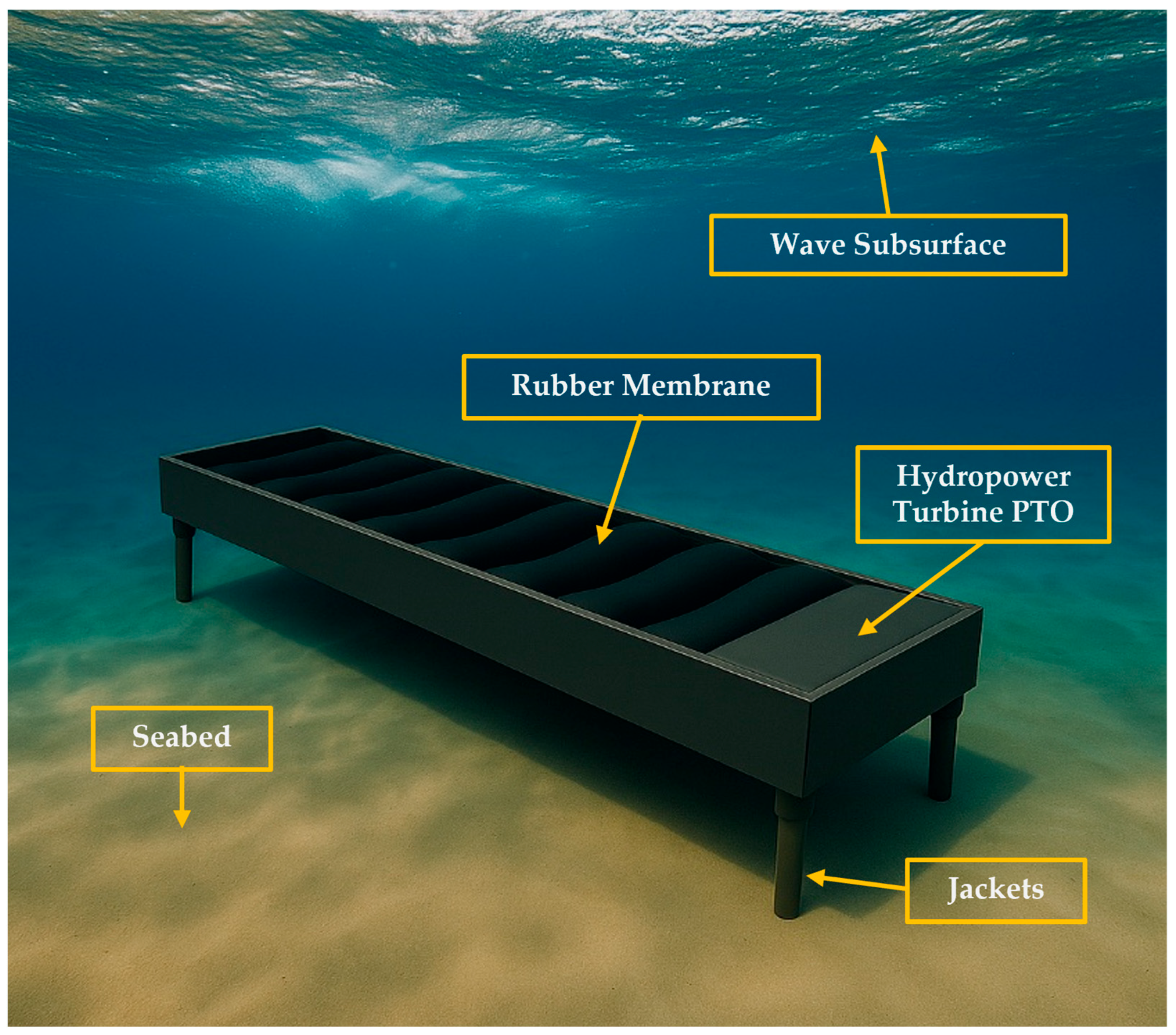
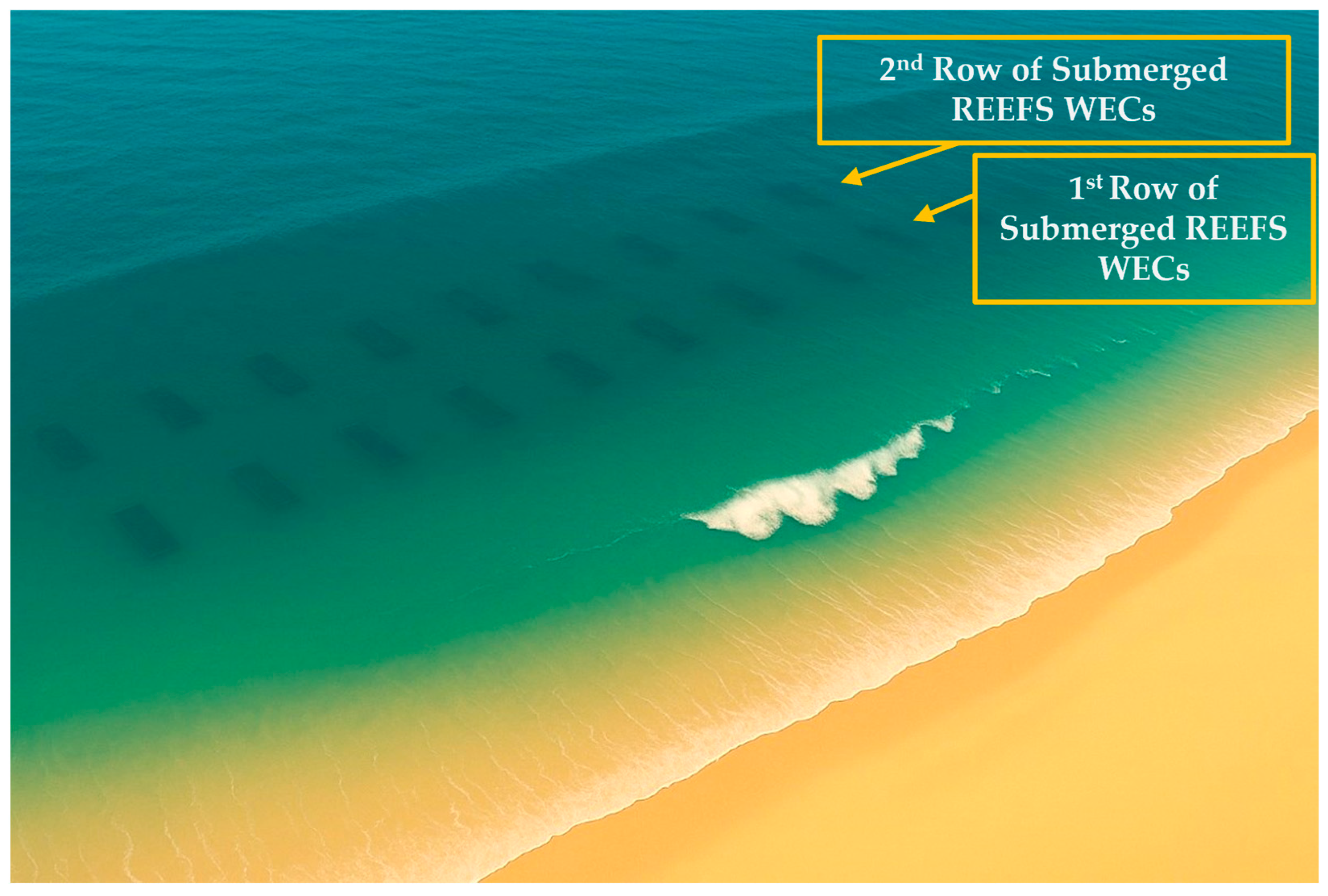
An illustration of the device nearshore installation is depicted in Figure 1.

1.3. Scope of the Article

The development trajectory of the REEFS exemplifies the complexities inherent in the invention and maturation of wave energy technologies. From early-stage laboratory experimentation and advanced numerical simulations to the current deployment in the coastal waters, REEFS has developed considerably. This journey has involved the analysis of technical, environmental, and regulatory challenges, which reflect the broader hurdles faced across the sector.
This work traces that trajectory, describing and highlighting the key milestones leading up to the current research status, which comprises the ongoing installation of a model in the seawaters of the Port of Sines, Portugal. The obstacles that have been overcome along with those that still persist are discussed in order to provide a comprehensive example of the development challenges associated with the REEFS WEC, which can be valuable for other researchers pursuing similar approaches.

2. Materials and Methods

The development challenges of an emerging WEC may vary, depending on the type of device and on the project phase TRL. In this study, the case of the nearshore SPD REEFS WEC is analyzed to identify the main development challenges involved, from the beginning of the project until today, also featuring the future challenges. The methodology employed was based on the analysis of published and unpublished scientific materials about the REEFS concept, aiming to systematically outline the key stages of development, identify overcome and unresolved challenges, and present the ongoing or proposed near future solutions.
The materials came from three primary sources: (i) peer-reviewed scientific publications authored by the REEFS research team, covering various phases of the device’s development—from initial concept validation to physical modeling and computational simulations; (ii) technical documents and internal reports produced within the REEFS project, including unpublished articles made available by the research team; and (iii) first-hand experience of the authors.
The first author is the inventor of the REEFS WEC and the coordinator of the research group. He is the pivotal element that has been accompanying the project since the beginning centralizing research outcomes of several MSc., Ph.D. students, as well as research fellows that participated in this project. The second author has developed the MSc. thesis on structural modeling of the REEFS device. Since then, he has been actively contributing to the project as a research fellow over the past three years, having a global perspective of ongoing works.
The approach is organized chronologically, following the next main topics: (i) concept presentation and first proof-of-concept; (ii) preliminary laboratorial determination of the REEFS WEC power output; (iii) simplified model for expedient computational assessment of the novel REEFS WEC power output; (iv) demonstrating the shore protection environmental externality; (v) CFD-based numerical wave tank of the REEFS WEC—wave flow modeling; (vi) first wave-to-wire proof-of-concept of the first version of the REEFS patent at (3:100) scale—turbine in contact with seawater; (vii) first wave-to-wire proof-of-concept of the second version of the REEFS patent at (3:100) scale—turbine without contact with seawater.
Complementarily, the approach outlines the current research status considering the following topics: (i) CFD-based numerical wave tank of the REEFS WEC—fully functional wave-to-water modeling; (ii) sea test of the REEFS model in Port of Sines, Portugal.

3. Results

This chapter presents two types of results: those related to the analysis of the development trajectory, and those derived from the current research status.

3.1. Development Trajectory

In this subsection, the development process is revisited through a chronological criterion. The key challenges are outlined, emphasizing those that have been addressed, as well as those that persist, which will be further discussed in the subsequent sections.

3.1.1. Concept Presentation and First Proof-of-Concept

The REEFS concept was introduced to the international scientific community in 2017 [21]. Experimental proof-of-concept testing was conducted in a (1.5:100) small-scale model installed in a wave flume, focusing on five objectives: (i) demonstrating automatic activation of the variable porosity system by wave-induced pressures; (ii) confirming unidirectional inner water flow to drive a low-head turbine; (iii) comparing energy harnessing efficiency with run-of-the-river hydropower; (iv) evaluating the impact of stay vanes, and (v) verifying the device’s ability to induce wave breaking. The tests confirmed continuous unidirectional turbine rotation reaching up to 170 rpm and demonstrated REEFS’ capability to induce wave breaking, essential for its coastal protection function. Efficiency measurements indicated that REEFS could capture 20–40% of the power compared to a small-scale river dam under equivalent gross head continuous flow, despite limitations imposed by laboratory conditions, such as the absence of lateral energy flux and the use of regular rather than irregular waves. The stay vanes notably increased power extraction validating their inclusion in the design [21]. The lab proof-of-concept was used to introduce the concept to the University of Coimbra (UC) research and development ecosystem. It had a strong impact in mobilizing their receptivity and involvement.
An invention patent request had been submitted by the first author, in order to protect the intellectual property and simultaneously confirm the novelty of the concept. Initially, the project was funded using internal resources from the regular research support budgets of the Department of Civil Engineering (DCE) [77] and the MARE research centre [78]. However, as the costs increased, it became necessary to apply for co-funding, through which a grant was successfully secured from a program for protection of intellectual property of the regional operational programme for Portugal centre region 2020 [79].
At this stage, the main overcome challenges shown in [21] can be summarized as follows: (i) it was shown that both kinetic and potential energy from waves can be harvested within the same device; (ii) it was proved that the passive variable porosity system is able to create an inner continuous flow, requiring no sensors or actuators, solely by wave-induced forces; (iii) it was demonstrated that the device can drive an axial turbine unidirectionally, despite the oscillatory wave motion; (iv) it was validated that the device can induce wave breaking, supporting its multipurpose function.
However, it was clear that many important challenges had yet to be overcome such as the following: (i) further lab and real-sea testing to compute performance under more accurate conditions; (ii) quantifying the multipurpose shore protection externality of the device; (iii) optimizing turbine design specifically for wave-driven low-head applications, because the off-the-shelf lab turbine was not custom-designed; (iv) integrating advanced numerical modeling to refine design parameters and predict performance under more diverse marine conditions; (v) assessing long-term durability regarding biofouling, corrosion, sediment abrasion, and storm survival; (vi) performing environmental impact assessments to ensure ecological sustainability; (vii) conducting technical and economic feasibility studies for large-scale deployments.

3.1.2. Preliminary Laboratorial Determination of the REEFS WEC Power Output

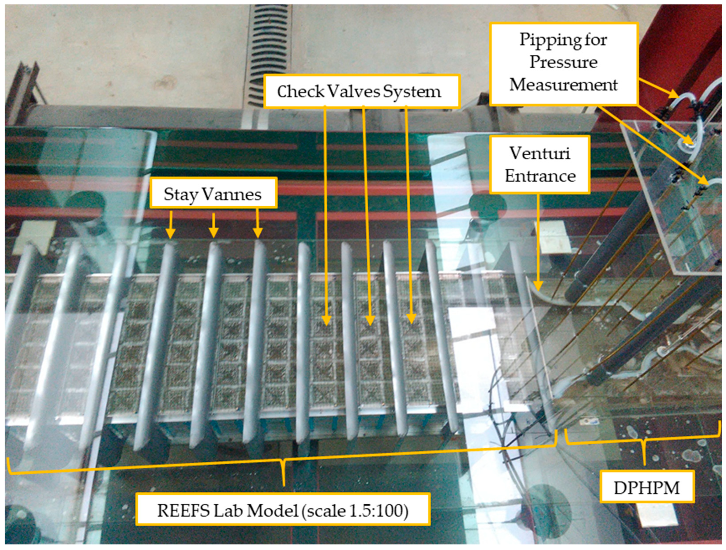
The most important challenge to overcome was clearly identified in the previous paragraph as the need to compute the device’s performance under more accurate conditions. Therefore, in 2018 a preliminary laboratorial determination of the REEFS WEC power output was performed as presented in [80]. To accurately estimate the power output while avoiding the complexity of a custom-made hydropower unit, the turbine was replaced by a Differential Pressure Hydraulic Power Meter (DPHPM). This device uses head loss across a calibrated valve to simulate energy extraction, allowing direct measurement of hydraulic power harnessed from wave motion. The DPHPM was rigorously calibrated in a small flume using Venturi principles, achieving a reliable discharge coefficient of 0.910 [80].
A (1.5:100) small-scale REEFS model was tested in a 36 m wave flume of the Laboratory of Hydraulics, Water Resources and Environment (LHWRE) under various controlled wave periods and heights representative of Portuguese coastal sea conditions, using Froude similarity. The experiments assessed wave periods from 0.73 s to 2.08 s and wave heights from 0.75 cm to 8.25 cm, corresponding to real scale wave periods from 6 s to 17 s and wave heights from 0.5 m to 5.5 m, capturing data on pressure differentials and wave breaking behavior with micromanometers and synchronized video footages, respectively [80]. Figure 2 presents details of the laboratory installation.
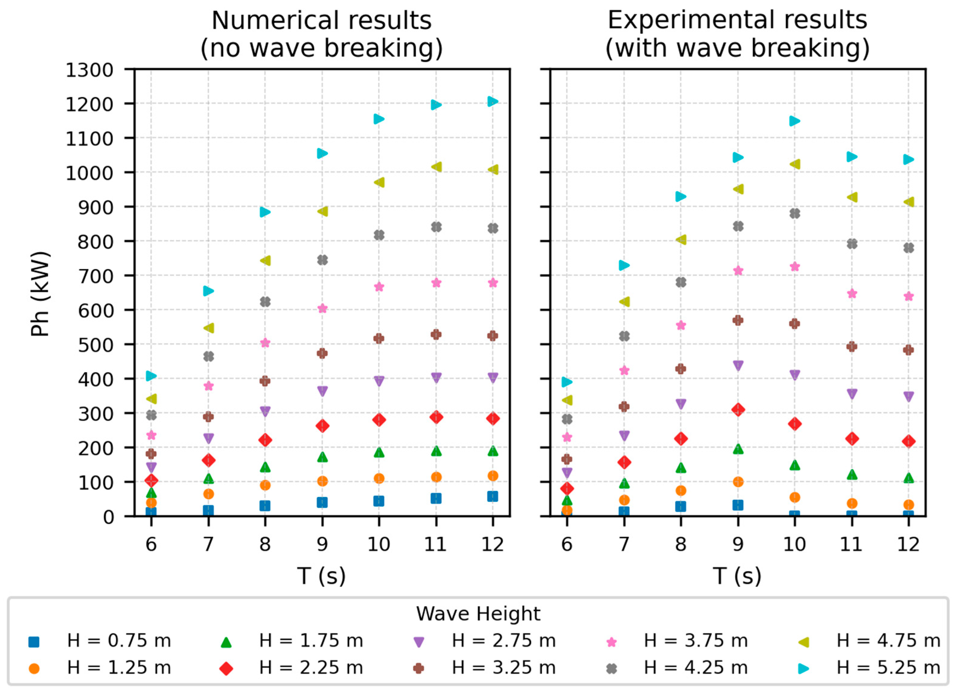
Results revealed that hydraulic power output increases with wave height but begins to plateau due to energy dissipation once wave breaking occurs, demonstrating REEFS’ potential dual role as an energy dissipator and wave energy converter. Power output extrapolated to real scale exhibited peaks at wave periods of 9–10 s and at an exploratory period of 17 s. The wave-to-water conversion efficiency ranged between 15 and 30%, with potential to increase because no optimization of stay vanes, intake, outlet, variable porosity system, device dimensions nor deployment depth was performed yet [80].
Power performance was extrapolated to real scale. Despite the conservative approach and limitations of the regular wave testing in a controlled environment, the REEFS demonstrated comparable power output per unit width to other WECs in the literature while maintaining environmental advantages in invisibility (fully submerged) and costal protection (wave breaking) [80].
The main challenges overcome at this stage included the following: (i) development of a practical, low-cost accurate laboratory method (DPHPM) to measure the power captured by a WEC without requiring a costly customized turbine; (ii) successful calibration, in a small-scale flume, of the DPHPM with high precision, ensuring reliable power measurement; (iii) achieved to evaluate energy extraction behavior across a wide range of wave heights and periods in a controlled environment; (iv) extrapolated real scale captured power of the REEFS device using Froude similarity; (v) evidence of partial wave energy dissipation leading to a stabilization of the maximum captured power as wave height increases.
The encouraging laboratory power output figures called attention to the need for more tests at a larger scale. However, the model design needed to be previously checked in terms of major governing parameters such as length, width, height, and deployment depth.
Therefore, at this stage, the need to develop a computational model of the device emerged as the main next challenge.

3.1.3. Simplified Model for Expedient Computational Assessment of the Novel REEFS WEC Power Output

In 2020, a fast-running simplified mathematical model to predict REEFS energy output under Stokes second-order water wave theory was introduced in [81]. This was a time-saving tool that facilitated the early parametric exploration and optimization of the model design.
Given the novelty of the REEFS concept, existing numerical models could not be directly applied for power output assessment and optimization. Therefore, a dedicated device-specific computational model was developed, balancing simplicity with sufficient physical accuracy to enable rapid, exploratory simulations needed during the early development stages. The model utilizes Stokes second-order wave theory to compute subsurface pressure and velocity fields, while mass and energy conservation laws are applied to simulate steady internal flows within the REEFS hydraulic circuit [81]. The model accounts for frictional energy losses, inlet and outlet valve response to dynamic pressure, and stay vane effects. It is implemented in FORTRAN, requiring low computational memory and achieving fast run times (about 1.5 min on a standard PC), making it practical for extensive sensitivity analyses [81].
To validate the model, numerical simulations were compared against previous small-scale laboratory experiments performed under controlled regular wave conditions. These tests used Froude similarity to scale wave conditions representative of the Portuguese coast. Results demonstrated good agreement between simulated and experimental data, with a global correlation coefficient of 0.986 for power output and 0.988 for internal flow rates, indicating the model’s reliability in capturing the REEFS system’s power output behavior [81].
The analysis revealed that power output increases nonlinearly with wave height, and although it generally increases with wave period, this growth flattens for longer periods due to the device’s finite length, as presented in Figure 3. The model highlighted the lack of wave-breaking criterion causing power output overestimation under large wave heights and periods. Similarly, discrepancies at low wave heights were attributed to valve dynamics not fully captured by the invariable head loss coefficients used during calibration [81].
Despite these limitations, the model effectively demonstrated the impact of wave conditions, deployment depth, and geometry on the REEFS device’s performance, providing a practical tool for guiding design and deployment optimization while reducing dependence on costly time-consuming laboratory tests.
It was concluded that incorporating wave-breaking criterion, adding cnoidal wave modeling for shallow water conditions, and refining inlet/outlet head loss coefficient parametrization will further improve the model’s accuracy, in order to support the continued development and scaling up of the REEFS [81].
The main challenges overcome at this stage were as follows: (i) development of a dedicated, device-specific computational model to assess REEFS power output; (ii) successful calibration and validation of the model against laboratory experiments, demonstrating its reliability; (iii) creation of a fast, lightweight simulation tool enabling sensitivity studies across wave heights, periods, and deployment depths; (iv) Provision of a computational tool for design optimization without relying solely on expensive laboratory testing.
However, the simplified computational model left important challenges still to overcome such as (i) incorporating wave-breaking criterion within the computational model to avoid power overestimation during high wave conditions; (ii) implementing cnoidal wave modeling for shallow water conditions where Stokes second-order theory become inadequate; (iii) implementing variable local head loss coefficients to reproduce inlet and outlet check valve geometry changes under wave action; (iv) improving the variable porosity system functioning that in reality is ruled by the natural water forces balance but was not effectively simulated that way in the simplified computational model. Instead, the criterion was purely based on the pressure profile induced by a Stokes second-order wave, irrespectively of the hydraulic impact of the device presence in the water media; (v) coupling the model with a full PTO computational model, comprising turbine and generator, to calculate wave-to-wire efficiency.
An important aspect observed during lab validation of the simplified model for expedient computational of the REEFS power output was the impact of the partial wave breaking in energy capture. Therefore, the evaluation of the wave-attenuation proportioned by the REEFS was elected as the next challenge of the development process. An experimental approach was chosen because, as previously mentioned, the simplified computational model could not incorporate the complex modeling of wave-breaking phenomena.

3.1.4. Demonstrating the Shore Protection Environmental Externality

The multipurpose functionality of the REEFS invention as an artificial reef is of great importance for environmental receptiveness in terms of future wave farm licensing, as well as for possible cost sharing with coastal management authorities. Therefore, it was felt that a quantification of the shore protection potential was needed to support concept dissemination and provide evidence to improve future applications to funding calls. In 2020 [82], a laboratory assessment was performed to quantify the effectiveness of REEFS wave energy dissipating effect.
A (1.5:100) small-scale physical model was deployed in a controlled wave flume environment, simulating western Portuguese coast wave states using Froude similarity. Model wave periods varied from 0.73 s, 0.86 s, 0.98 s, 1.10 s, 1.22 s, 1.35 s, 1.45 s, plus an exploratory period of 2.08 s, covering a range of real scale wave periods from 6 s to 17 s. The model wave heights varied from about H = 1 cm to H = 9 cm, and the water depth d = 27.5 cm corresponding to real scale heights from H = 0.7 m until H = 6 m and water depth d = 18.3 m [82].
Wave energy dissipation was quantified by comparing upstream and downstream wave energy spectra, derived via discrete Fourier transform of water level time series obtained from resistive wave gauges. The experimental campaign included 260 tests covering a range of incident wave periods and heights. Two configurations were analyzed: (i) without exterior stay vanes and (ii) with exterior stay vanes installed [82].
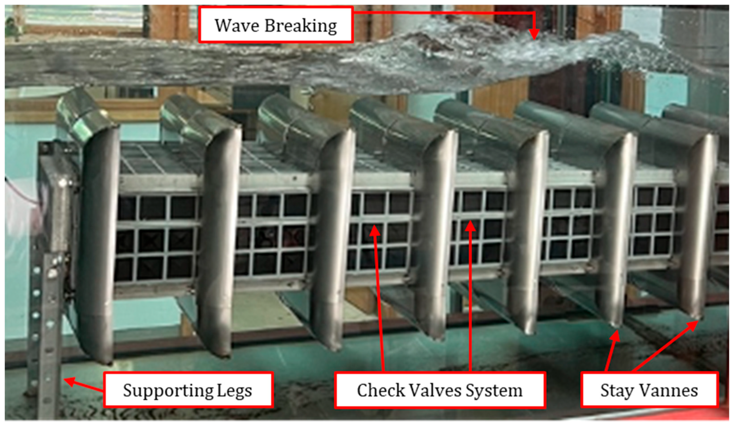
Results demonstrated that the REEFS device is capable of dissipating significant portions of incoming wave energy. Energy dissipation exhibited an inverse relationship with incident wave period, with higher dissipation for short waves and diminishing efficiency for longer waves. The device without stay vanes achieved an average energy dissipation of approximately 43%, while the configuration with stay vanes reached 68%, approaching the lower range of submerged breakwater performance values reported in the literature (80–90% for short waves). Spectral analysis revealed that dissipation was associated with wave breaking and nonlinear energy transfer to higher harmonics, consistent with behavior observed in natural surf zones [82].
These findings validate the REEFS device as a dual-purpose infrastructure, combining renewable energy potential with coastal protection contribution.
The wave breaking induced by the REEFS was later confirmed in the (3:100) small-scale model as shown in Figure 4.
At this stage, the key challenges addressed in the study can be summarized as follows: (i) successful design and execution of the first physical model test validating REEFS externality of energy dissipation with potential for shore protection; (ii) component innovation through the demonstration of the functional contribution of exterior stay vanes, resulting in a significant improvement in energy dissipation; (iii) comparative benchmarking that positioned REEFS performance near the lower limit of the energy-dissipating capacity of conventional submerged breakwaters.
However, remaining challenges persisted such as the following: (i) current analysis focused on monochromatic waves; performance under realistic irregular and multidirectional wave conditions remains unknown; (ii) the study excluded turbine operation which can capture some extra energy. Assessing energy dissipation during power generation is necessary to fully understand multipurpose functionality; (iii) structural stability and survivability under extreme storms was not assessed because of the limited power of the wave maker flume (maximum model wave height corresponds to a 6 m prototype wave height); (iv) further research is needed to optimize vane geometry and device placement for different coastal settings.
All these complex phenomena of fluid–structure interaction such as reflection, dissipation and transmission of the wave energy, with wave breaking conditioned by the stay vanes size and geometry, combined with the under pressure transient flow created by the combined action of the inlet and outlet check valves that produce the inner flow that drives the inhouse hydropower turbine, require a sophisticated powerful modeling tool. The experimental approaches adopted so far are revealed to be costly and very time-consuming. Therefore, the development of a CFD numerical wave tank of the REEFS was elected as the most important challenge, in order to provide advanced numerical modeling to refine design parameters and predict performance under broader maritime conditions. This will enable an improved evaluation of the REEFS, which is needed to feed the technical and economic feasibility studies of future large-scale deployments.

3.1.5. CFD-Based Numerical Wave Tank of the REEFS WEC—Wave Flow Modeling

The experimental wave attenuation study showed there is a complex wave–structure interaction leading to wave breaking over the device. To fully replicate this dual-purpose functionality, a more complex computational model was needed. In 2022, a CFD-based numerical wave tank (CNWT) developed for REEFS was introduced in [83]. It represented a significant step forward in the efficient and accurate analysis of the REEFS concept, aiming to support detailed investigation of wave energy harnessing while facilitating simulation of shore protection by wave breaking.
The CNWT was implemented using the Reynolds-averaged Navier–Stokes (RANS) equations combined with the Volume of Fluid (VOF) method to capture the free surface, using ANSYS Fluent 2023 R1 as the computational framework. An incremental validation methodology was adopted: (i) two-dimensional wave-only simulations to define optimal spatial and temporal discretization via convergence studies, and (ii) full three-dimensional wave–structure interaction studies including the REEFS device geometry. Numerical results were validated against laboratory data collected from a physical wave tank using a (1.5:100) small-scale REEFS model tested under regular wave conditions [83].
The 2D convergence studies determined that a minimum mesh refinement of 20 cells per wave height and 100 cells per wavelength, combined with a temporal discretization of T/200, ensured accurate free surface and velocity field predictions, with wave height errors below 1.1% upstream and 2.3% downstream. For 3D simulations, the model exploited geometric symmetry to reduce computational effort, achieving accurate free surface reproduction with a mean wave height error below 3.5% relative to full-domain simulations. Advanced free surface capturing was achieved by combining second-order implicit time discretization and a high-resolution interface capturing scheme (HRIC), maintaining Courant numbers below 0.3 to ensure low diffusion of the water–air interface [83].
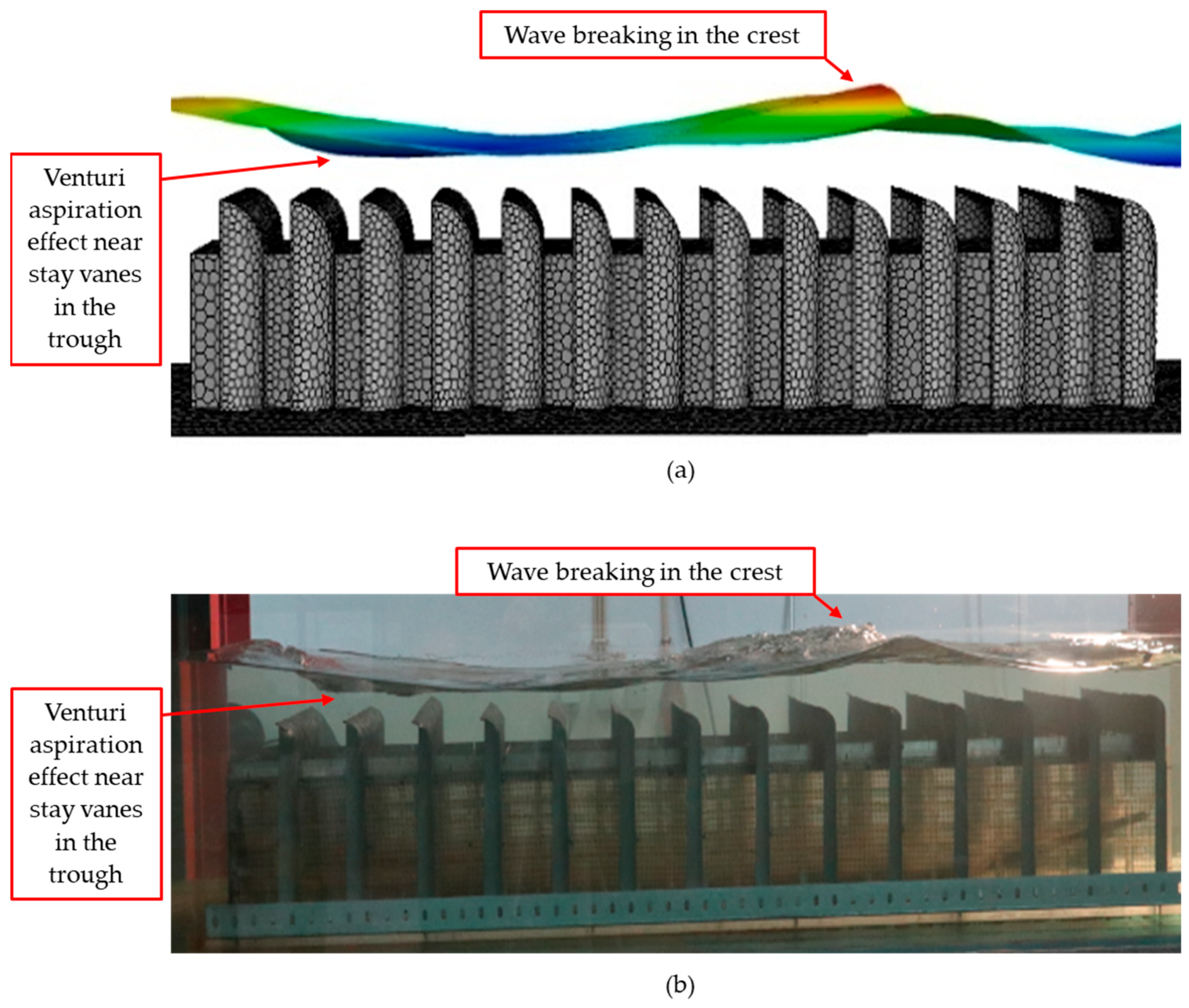
Wave–structure interaction analysis showed that the CNWT reproduced the expected energy dissipation effects of REEFS when configured in a passive mode (turbine inactive). Experimental and numerical comparisons of zero-order spectral moments of the wave energy density confirmed good agreement both upstream and downstream of the device. Furthermore, the model captured local complex hydrodynamic phenomena, such as the wave breaking in the crest of the wave and the Venturi aspiration effect near the device’s stay vanes in the wave trough, which are difficult to quantify experimentally [83].
The validated CNWT offers several advantages for REEFS development, including the ability to simulate complex, nonlinear flow regimes without the limitations of physical tanks (cost and time-consuming), and flexibility to analyze device performance under different sea states and device configurations.
Figure 5 exemplifies the good agreement found between the free surface configuration computed by the dedicated CNWT and obtained in the laboratorial experiments with the physical small-scale model.

3.1.6. First Wave-to-Wire Proof-of-Concept of the First Version of the REEFS Patent at (3:100) Scale—Turbine in Contact with Seawater

While the CNWT aligns well with simulations in shut-down storm conditions (inner hydraulic circuit closed and no power production), the challenge of adding the PTO and the variable porosity check valve system will require a new physical model to validate a complete CFD-based numerical wave tank of the REEFS.
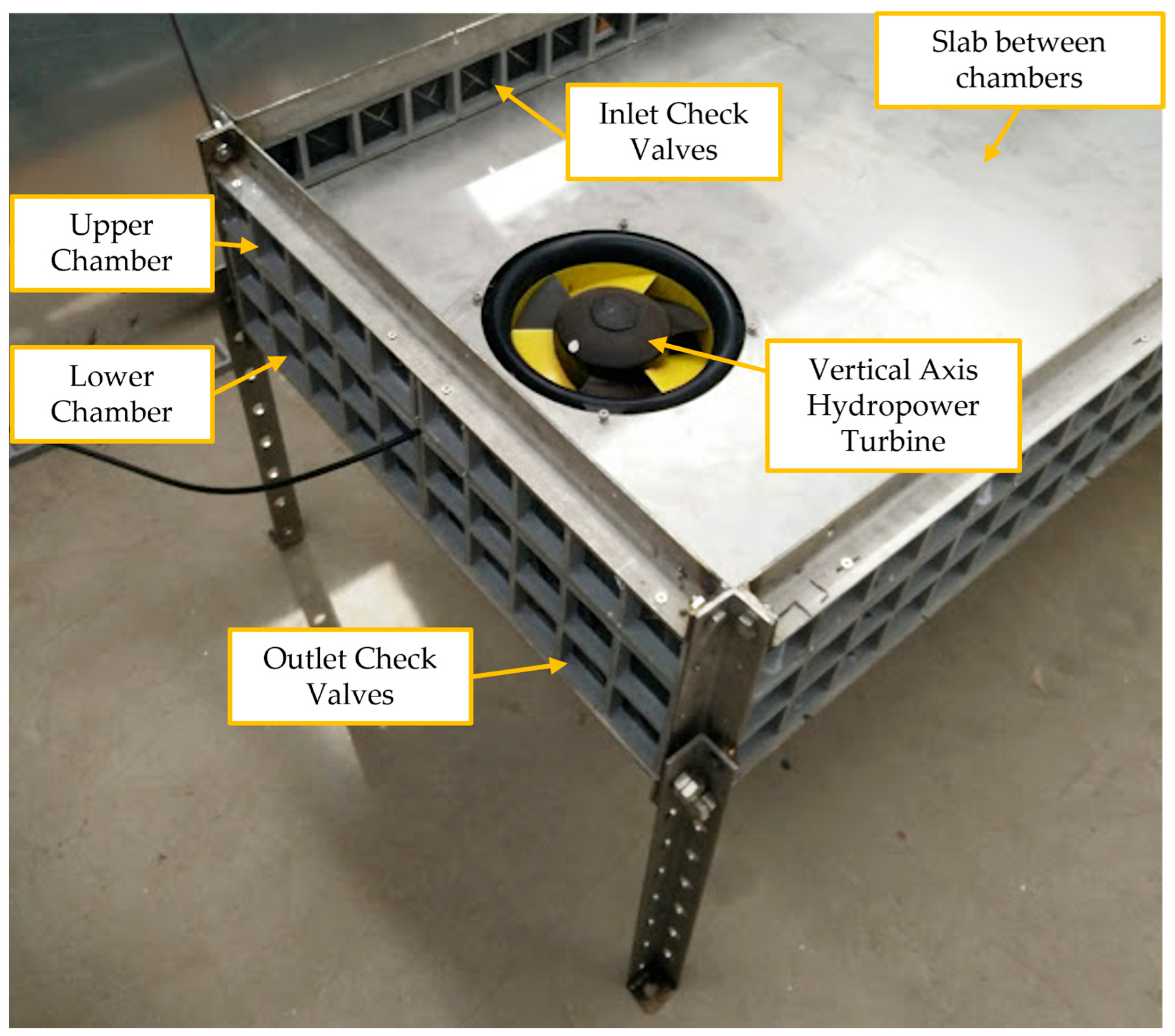
Therefore, in 2022, an effort was made to build a new small-scale (3:100) lab model of the REEFS device including all the components. The model was constructed in stainless steel and fiberglass-reinforced polymer (FRP). There is a horizontal slab dividing the upper chamber from the lower chamber. The upper chamber is responsible for water intake which occurs when inlet acrylic check valves open below the wave crest. The lower chamber allows water expulsion when outlet check valves open below the trough of the wave. Somewhere between these chambers there is a PTO to convert the captured hydraulic power into electric power, consisting of an off-the-shelf axial hydropower unit manufactured by WaterLily [84]. This version also supports the use of support legs and stay vanes. Next, Figure 6 presents a photograph of the turbine locations in the horizontal internal slab.
This model provided the first wave-to-wire proof-of-concept of the REEFS. Besides the need to validate upcoming upgraded versions of the CNWT of the REEFS, it revealed that it was of upmost importance to disseminate the project and facilitate fund raising. It was used by the UC Business—Technology Transfer Office [85] to prepare calls for funding and approach potential investors.
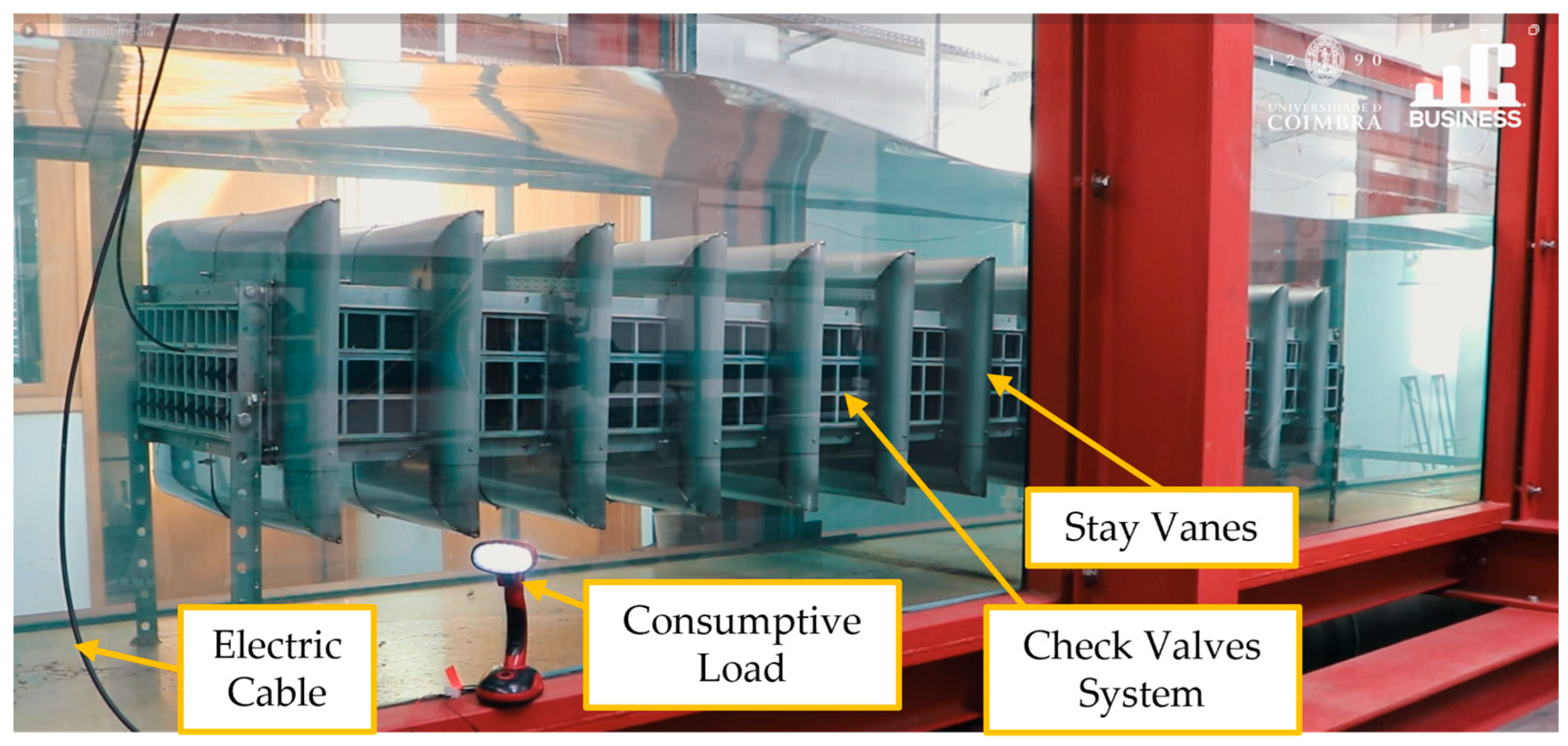
Figure 7 presents a snapshot of the complete wave-to-wire proof-of-concept video published since 2022 in the web site of the UC Business—Technology Transfer Office of the University of Coimbra (Portugal) [85].
Up to this stage, funding has been secured through internal resources of the DCE and the MARE research centre [78]. However, to increase the project’s TRL and make it attractive to industry stakeholders, it is necessary to build larger-scale demonstrators and transition from a laboratory setting to a real maritime environment. Consequently, the primary challenge becomes the search for external funding to support this transition. This is a struggling phase of the development process that consumes a lot of effort from the project promoter. The so called “death valley” phase arises, i.e., the applied and potentially commercial character of the project makes it ineligible for pure scientific funding calls. On the other hand, it is not yet attractive to industry because it has a low TRL.
After applying to several funding calls, success was finally achieved by the end of 2022, through a consortium project entitled NEXUS: Innovation Pact—Green and Digital Transition for Transport, Logistics and Mobility [86]. Under work package 8.3 of this initiative, research work begun in 2023, and the installation of a fully functional REEFS model in the waters of the Port of Sines is planned by June 2026. The participation of the Ports of Sines and the Algarve Authority, SA (APS) has been of synergic usefulness due to the exchange of information and discussion about the Port of Sines, which are of upmost importance to prepare the pilot test of the small-scale model of the REEFS.

3.1.7. First Wave-to-Wire Proof-of-Concept of the Second Version of the REEFS Patent at (3:100) Scale—Turbine Without Contact with Seawater

Work package 8.3 of the NEXUS project [86] culminates with the deployment of a small-scale (1:10) REEFS model at the Port of Sines.
Within the scope of this project, a second version of the REEFS patent was implemented in 2023. This new design introduced a significant innovation: an elastic membrane enclosing the check valves, thereby fully isolating the device’s internal volume from the external marine environment. The internal chamber is intended to be filled with freshwater, establishing a closed-loop hydraulic circuit in which the turbine does not come into direct contact with seawater. This configuration offers advantages in terms of corrosion prevention, fouling mitigation, and long-term maintenance.
The small-scale model was constructed using acrylic and fiberglass-reinforced plastic (FRP) at the same geometric scale as the previous model (3:100), enabling direct comparison of performance between both configurations and selecting the most suitable version for future large-scale deployment at the Port of Sines.
In this version, the internal chamber is vertically divided into inlet and outlet sections connected to the turbine. A key feature is the implementation of an elastic membrane placed above the redesigned check valves, which are now positioned exclusively on the upper surface of the device. This alternative design transmits wave-induced pressures through the elastic membrane to the interior water mass, enabling energy conversion while preventing the entrance of marine organisms or sediments. The use of transparent acrylic allows for direct visual monitoring of internal processes, including membrane deformation, valve actuation, and turbine response. As with the previous version, this model can accommodate support legs and stay vanes.
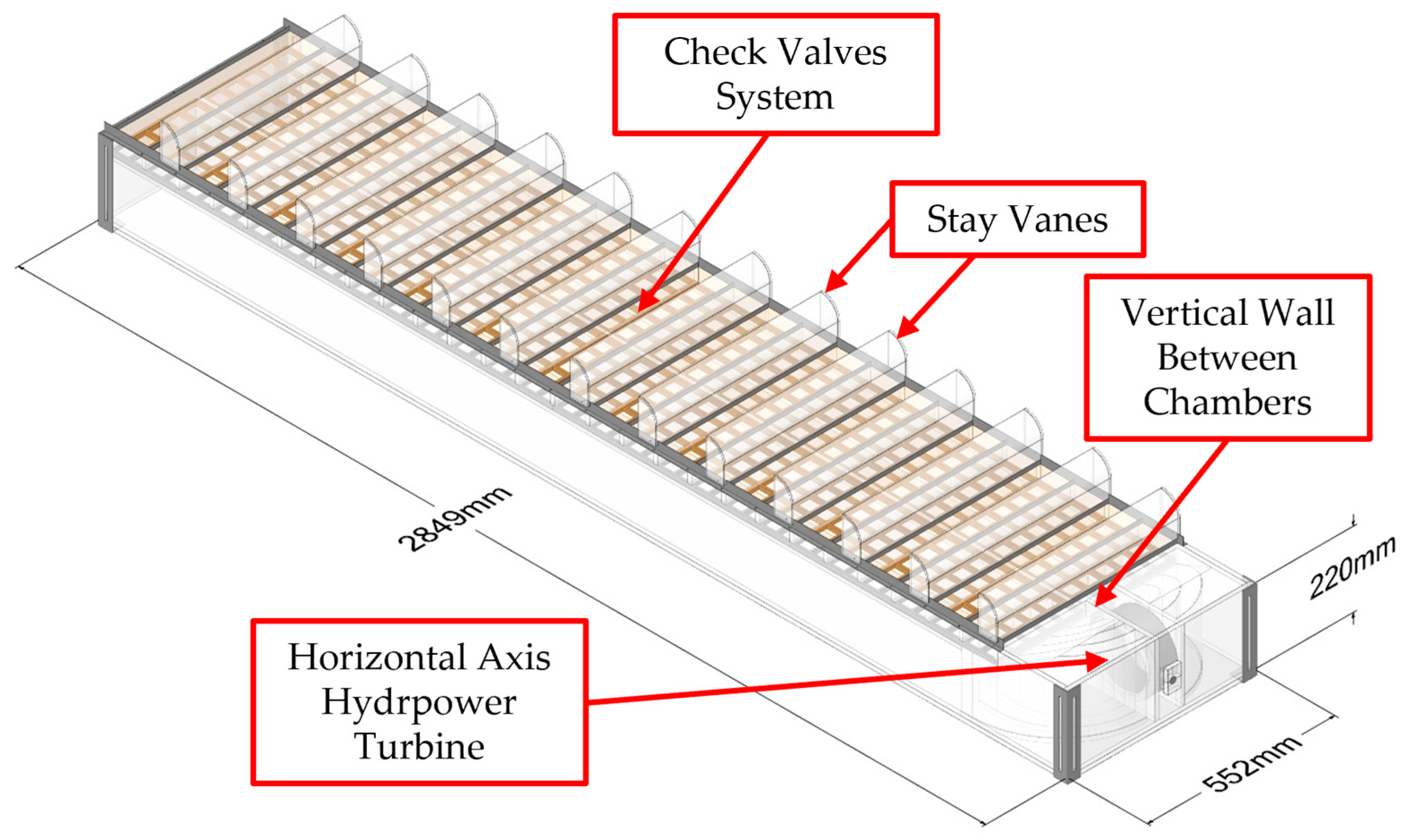
Figure 8 illustrates the REEFS small-scale model without support legs but with transparent stay vanes and membranes (a transparent membrane was considered to allow the visualization of the quadrangular check valves located below it).
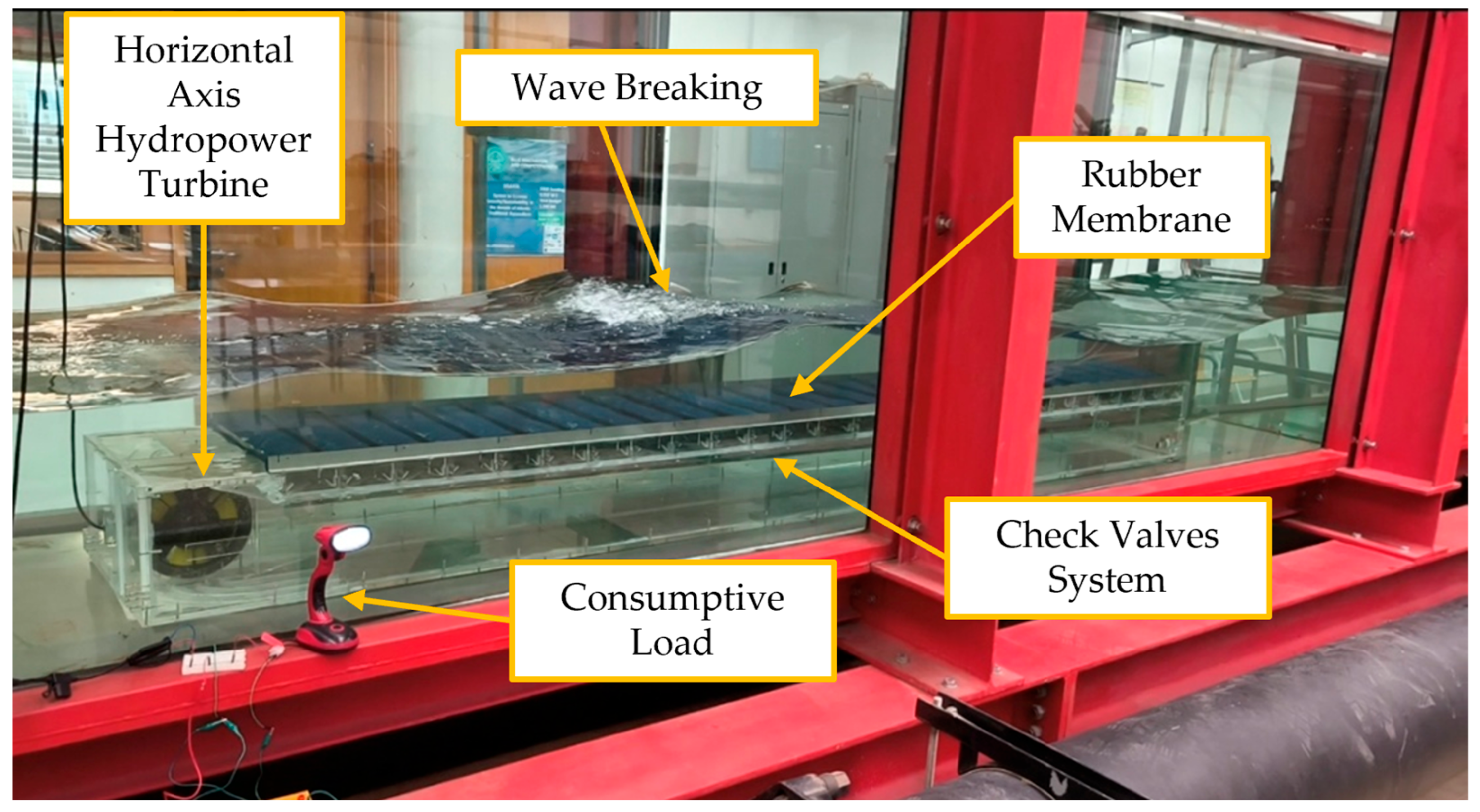
To demonstrate the performance of the membrane-based version of the REEFS, proof-of-concept experiments were conducted in the wave flume of the LHWRE at the DCE of UC. A configuration without support legs or stay vanes was tested under the same wave conditions as the previous non-membrane version. The results confirmed the full operability of the membrane version. Figure 9 presents an example for a wave period of T = 1.4 s, wave height H = 8 cm, and water depth d = 43 cm, where wave breaking over the device is clearly visible, together with simultaneous energy production, demonstrated by the lit lamp.
Since the membrane-based version of the REEFS WEC provides protection to the turbine against marine flora, fauna, and sediments, it was selected for installation at the Port of Sines to minimize risks, as this will be the first time the concept is tested at sea.

3.2. Current Research Status

Several research tasks are being undertaken with the ultimate goal of converging to a pilot project in the sea. Next, the main challenges associated with the current research status are outlined.

3.2.1. CFD-Based Numerical Wave Tank of the REEFS WEC—Fully Functional Wave-to-Water Modeling

To support the design of the (1:10) small-scale REEFS, optimizing both the device’s geometry and its deployment depth is essential.
A suitable balance must be achieved between sufficient water depth to ensure storm protection—through both kinetic energy and wave-induced pressure decay associated with submergence (e.g., [87] pages 79–81, 83–85)—and avoiding excessive depth, so that adequate kinetic and pressure-induced forces remain available to achieve efficient energy capture.
Therefore, a CNWT was developed, incorporating a simplified yet representative configuration of the enveloping variable porosity check valve system, to assess its hydrodynamic performance. Several modeling strategies were evaluated to achieve a good compromise between fluid dynamics accuracy and computational costs.
The initial geometry was based on the (3:100) small-scale REEFS model depicted in Figure 8, simplified to a basic version without membrane and without stay vanes. Key features such as valve layout, turbine orifice dimensions, and internal chamber structure were preserved. To reduce the computational cost, only one row of inlet and one of outlet check valves were considered. Accordingly, the device width was reduced, and the computational domain was defined to slightly exceed it.
The domain length was five wavelengths (L). The computational domain was discretized using poly-hexcore elements, with local refinement applied in the wave amplitude region and around the obstacle. A minimum resolution equivalent to 20 cells per wave height was imposed in these zones, with a growth rate of 1.2. Outside the refined regions, the maximum cell size was allowed to increase up to three times that of the refined zone. The domain height was set to 1.5 times the water depth. The WEC was positioned one wavelength away from the inlet boundary. Following the methodology adopted in [83], the final two wavelengths of the domain included a numerical beach to dissipate wave energy, using the same damping coefficients as in [83]. The implemented mesh comprised a total of 1,164,276 cells.
At the inlet boundary, second-order Stokes wave theory was directly applied to impose the desired wave parameters, while the outlet was set at the mean water level to allow free outflow. The total simulation time spanned eight wave periods (T), with a time step of T/400.
CFD simulations were carried out by solving the Reynolds-Averaged Navier–Stokes (RANS) equations using the Pressure-Implicit with Splitting of Operators (PISO) algorithm in a segregated manner. The Volume of Fluid (VoF) method was used to track the air–water interface. Gradient and pressure terms were discretized using the least squares cell-based (LSCB) and body force weighted (BFW) schemes, respectively. A second-order upwind scheme was applied for momentum terms in fully filled cells, while the High-Resolution Interface Capturing (HRIC) scheme was used near the free surface. Time integration employed a second-order implicit scheme.
The Shear Stress Transport (SST) k–ω turbulence model was used to capture flow details near walls and around the check valves. Double-precision computation and a residual convergence threshold of 10−4 were set to ensure numerical stability and accuracy.
To represent the check valves, a simplified method was adopted in which they were modeled as porous regions with variable pressure-loss coefficients, enabling a one-way flow behavior without the need for moving mesh or fluid–structure interaction. The turbine effect was approximated using a constant head-loss coefficient.
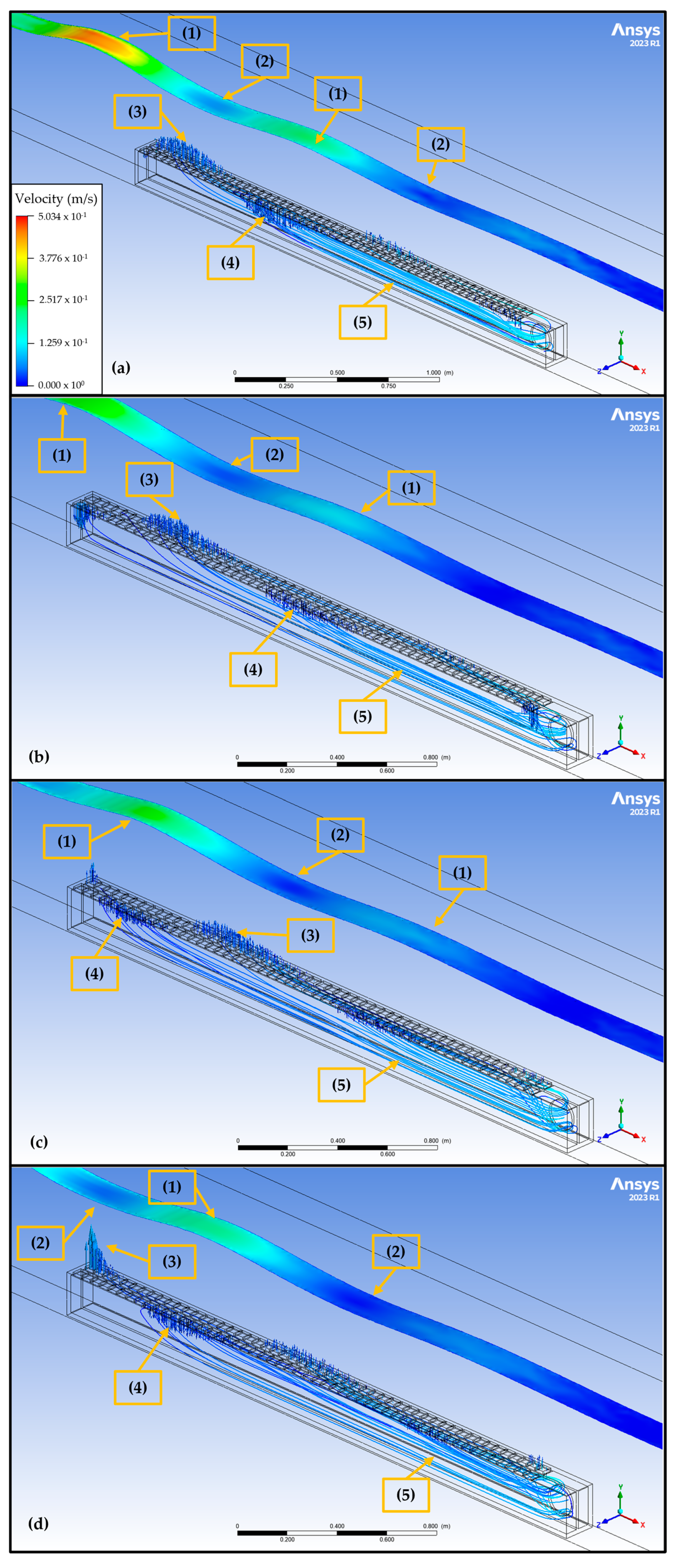
The CNWT was able to generate a continuous flow inside the REEFS device, created by an external nonlinear wave passing over the device combined with the autonomous functioning of the check valves activated uniquely by the natural water forces.
This CNWT simulation constitutes the first numerical wave-to-water proof-of-concept of the REEFS WEC. As shown in Figure 10, the horizontal streamlines (e.g., (5) in Figure 10) demonstrate that a continuous flow is created inside the device by the joint action of the inlet flow (e.g., (4) in Figure 10) combined with the outlet flow (e.g., (3) in Figure 10).
This simulation required approximately 16 h, performed on a workstation equipped with a 8 GB GPU, 128 GB of RAM (3200 MT/s), and a 16-core processor running at 3.40 GHz. The initial results are consistent with the expected physical response. However, the model still requires further computational settings to ensure practicality.
CFD tools offer substantial realism in the analysis of wave energy systems by enabling high-resolution simulations of complex three-dimensional fluid–structure interactions. These tools provide detailed spatiotemporal data on flow parameters such as velocity and pressure, which are essential for optimizing device performance and predicting operational behavior. However, these benefits come at a significant computational and methodological cost.
A systematic review conducted by [83] analyzed approximately 20 studies applying CFD techniques to the development of WECs. The review grouped and compared technical elements such as software platforms, numerical models, wave generation and absorption methods, turbulence modeling strategies, pressure–velocity coupling algorithms, mesh types, convergence analyses, and both spatial (e.g., cells per wavelength and wave height) and temporal discretization schemes (e.g., time-stepping methods, Courant number control). This broad diversity highlights the complexity and case-specific nature of CFD model development in this field.
In practice, setting up a reliable CFD model demands not only rigorous mathematical and experimental validation but also the careful selection of numerous interdependent parameters and modeling strategies. These decisions vary according to the specific physical scenario under study and require a deep understanding of both the physical processes involved and the numerical techniques employed. Expertise in turbulence modeling, free surface tracking, wave generation techniques, and mesh/time step optimization is crucial for achieving physically accurate and computationally stable results.
As highlighted by [83], there is no universally optimal CFD setup; each case demands a tailored approach. The RANS equations combined with the Volume of Fluid (VOF) method remain the most commonly used framework, with ANSYS (Fluent and CFX) and OpenFOAM as the predominant software. Alternative methods, like the Level Set technique in REEF3D as implemented in [88,89], offer higher spatial and temporal accuracy, minimizing artificial wave damping.
Turbulence modeling and pressure–velocity coupling (typically via the PISO algorithm) vary significantly across studies. Wave generation and absorption techniques also differ, generally producing satisfactory outcomes, further emphasizing the case-specific nature of CFD modeling.
Second-order spatial and temporal discretization schemes are widely adopted due to their accuracy in simulating wave propagation, whereas first-order methods often introduce damping as demonstrated in [90]. While mesh and time-step convergence studies are standard practice, numerical errors may still occur. Thus, quantitative assessments based on hydrodynamic parameter variation are preferred over purely qualitative evaluations.
Finally, it is important to highlight that the use of commercial software like ANSYS, though prevalent, may pose financial constraints, particularly in academic or early-stage research contexts. Despite its cost, ANSYS remains widely adopted due to its robustness and comprehensive modeling capabilities, as evidenced by its frequent appearance in the reviewed literature [83].
In summary, while CFD offers unparalleled insight into the performance and behavior of WECs, its application requires careful methodological planning, thorough validation, and substantial expertise.
Building upon these insights, the development of computational models for the REEFS WEC reflects many of the broader challenges identified in the literature. In line with the findings of [83], the modeling process demands a careful balance between numerical accuracy, physical realism, and computational efficiency. These considerations are particularly critical given the complex hydrodynamic and mechanical interactions that characterize the REEFS system. As such, the current research of CFD models for the REEFS not only seeks to complement experimental investigations but also aims to guide the design and optimization of larger-scale models through predictive simulation. This effort is supported by a modular parametrization strategy, which enables the system setting to be broken down into key subsystems—such as wave propagation, wave–structure interaction, check valve operation, internal flow dynamics, and turbine performance—each progressively refined and integrated to form a comprehensive representation of the device.

3.2.2. Sea Test of the REEFS Model in Port of Sines, Portugal

The Ports of Sines and the APS have demonstrated a strategic view regarding the expansion of the port’s renewable energy system. Given the current absence of standardized wave energy technologies in the market, APS is considering the deployment of the REEFS WEC developed at the UC in the APS maritime domain, over a defined operational period. The UC will handle the design, fabrication, deployment, operational management, and performance evaluation of a scaled-up (1:10) version of the existing wave-to-wire laboratory model. APS will act as the end user, while simultaneously gaining strategic valuable technological insights into this new wave energy technology. This project seeks to advance the TRL by demonstrating a functional product in a real maritime environment.
The evaluation of the Port of Sines as a potential deployment site marked an essential step in the planning and design of the upcoming (1:10) REEFS small-scale model. This stage involves the integration of multiple data sources and analytical methods, including model performance requirements, wave conditions at the port entrance, local wind-generated wave patterns, tidal regimes, bathymetric data, seabed characteristics, wave propagation within the harbor, and operational constraints.
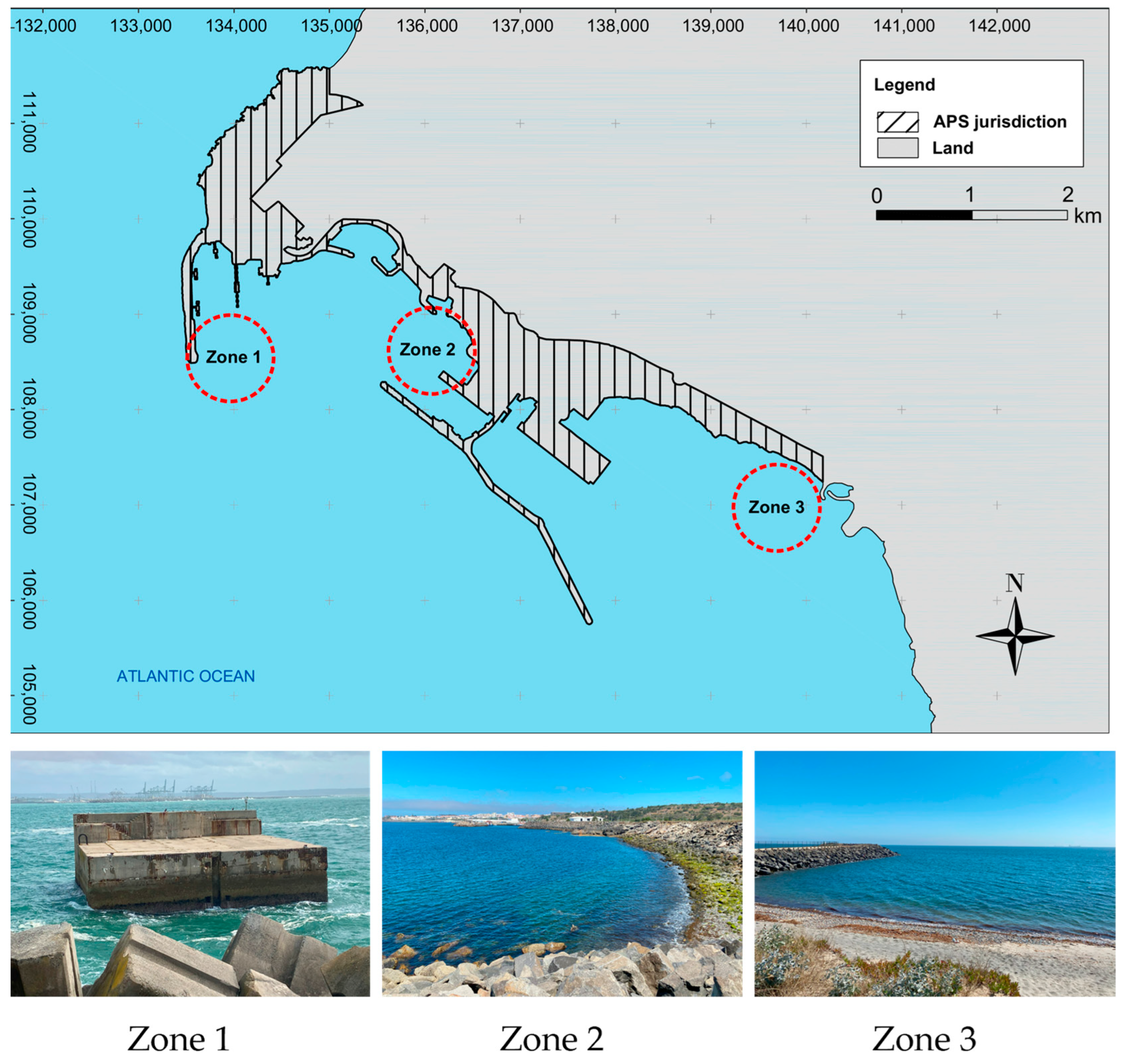
A comprehensive methodology was employed to identify feasible test zones as presented in [91]. The expected number of operational hours for the selected deployment period that will occur during the end of spring and beginning of summer of 2026, was estimated. The process involves statistical analysis of oceanographic and meteorological conditions, wave propagation modeling for a representative range of sea states, and the superposition of various spatial datasets. Three potential deployment sites are currently under consideration as shown in Figure 11.
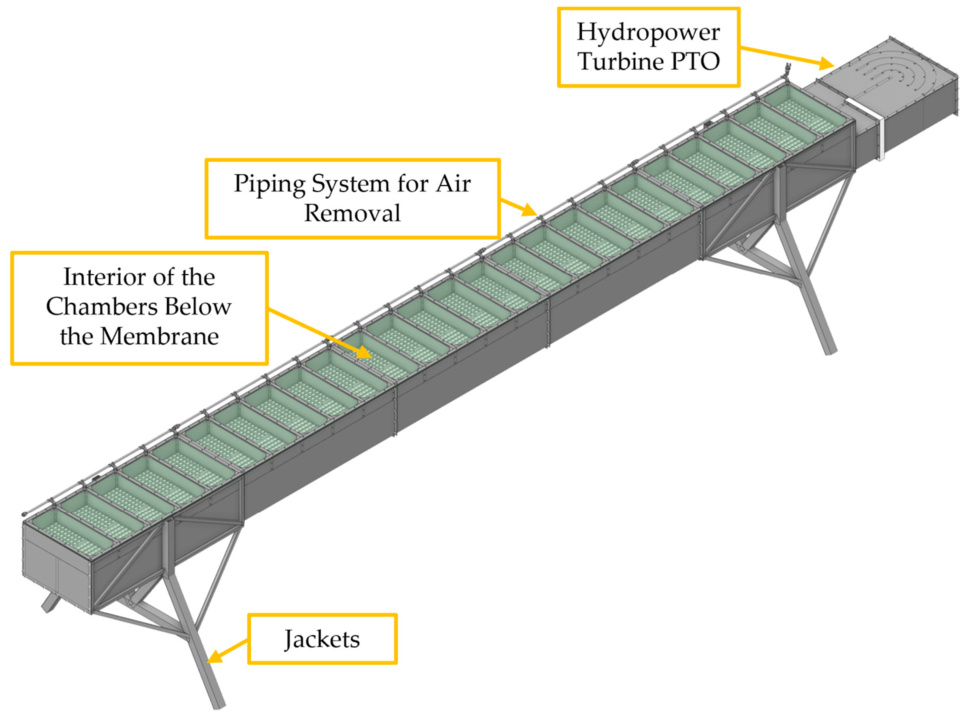
Besides site selection, current research focuses on the design, addressing not only hydrodynamic performance but also structural integrity, manufacturability, and field operations. Hydraulic and structural assessments are being conducted using ANSYS Fluent, ANSYS Mechanical and Autodesk Robot 2025 to verify the system’s resilience under extreme environmental loads and especially during installation and retrieval operations.
The logistics planning requires careful coordination of construction, transportation, and marine operations. This includes evaluating access routes, lifting procedures, use of tugboats, and the potential integration of equipment such as pneumatic rollers or floating bags. These aspects must be incorporated into the design ad init. to ensure full compatibility with field operation procedures.
Operational specific aspects such as air removal from the chambers for filling of the device with fresh water (membrane-based version), must also be incorporated into the deployment procedure. Adequate material selection for key components, like the check valves and the elastic enveloping membrane are currently being investigated, taking into consideration their mechanical properties and compatibility with marine environment.
A critical part of the model development involved selecting an appropriate turbine for the system’s operating conditions. Commercially available micro hydropower turbines, especially those designed for marine applications, were evaluated but ultimately found unsuitable due to their low efficiency at the expected head and flow conditions. Consequently, current research focuses on the specification and development of a turbine specifically designed for the REEFS model operating conditions.
Regarding the model structure there are two options being investigated: a metallic structure and a concrete structure.
The metallic structure is ductile, making it easy to transport and deploy, but more expensive to build, and less stable due to its low weight (in the range of 1–2 tons). On the contrary, the concrete structure is fragile and heavy, making it more difficult to transport and deploy, but less expensive to build. It is more stable due to its larger weight (in the range of 10–15 tons).
Given the research purposes of the (1:10) small-scale model, the option for a metallic structure is seen as more adequate in view of its higher logistic flexibility. However, at present state of research, the option for a concrete based structure for a real scale prototype is more adequate.
Figure 12 presents the current version of the metallic structure design of the (1:10) small-scale REEFS model.
Throughout the operational period, continuous monitoring will be conducted to collect key performance and environmental data. Parameters such as incident wave conditions, electrical power output, internal flow velocities, and pressures in the REEFS device will be recorded. This monitoring strategy will enable a comprehensive evaluation of the system’s behavior under real-sea conditions, although during the end of spring and beginning of summer to avoid destructive waves that would endanger the (1:10) small-scale model. The collected data will support the validation of numerical models, the evaluation of real-sea conditions efficiency, and provide insights for further design optimization.

4. Discussion

In this section the results presented in the previous section can be interpreted from the point of view of the challenges involved in the development process of novel WEC devices like the REEFS.
It is perceivable that the physical proof-of-concept is the main challenge because it captures the attention of both specialized researchers as well as the evolving community. This is very important to attract other researchers to the project and decisively strengthen applications to funding for both intellectual property protection and device design and construction.
The results show that the development process combines laboratory and computational modeling in a dialectical way. Indeed, the initial lab model provided validation/calibration for the simplified computational model which can be used to refine the design of the next larger lab model that will provide validation/calibration of more accurate CFD models of the device.
As the scale of the lab models increases it becomes possible to incorporate more realistic components such as the hydropower unit that was installed when (3:100) scale was achieved.
Results from the analysis of article authorship during the REEFS development indicate that coauthors’ contributions are often sporadic. This is due to the need to rely on students enrolled in MSc or PhD programs to perform specific research tasks. While students are generally eager to engage with the project, once they complete their courses, they must transition to other commitments, leading to a loss of valuable knowledge. This calls attention to the need for ensuring funding to build a stable research team where acquired know-how might be maintained.
Besides a stable research team, the project needs materials, equipment, and logistics to migrate from lab to sea at increasingly larger scales, i.e., from (1.5:100), (3:100) lab model scales to (1:10) sea model scale. Therefore, finding adequate funding emerges as a never-ending challenge of the development process.
The search for peer-reviewed scientific publications authored by the REEFS research team resulted in the identification of five articles covering a period from 2017 until 2022. It may be discussed that a higher number of publications should be expected given the novelty of the concept. Furthermore, it is known that the number of published peer-reviewed scientific articles is one of the most important decision criteria for research funding allocation, which is highly necessary to boost project development. However, paradoxically, a high number of scientific publications may excessively expose the invention, which is still being perfectioned, drawing the attention upon variants that may not be protected by the base patent. If the patent fails to fully protect the invention, the commercial value might be strongly compromised.
The development of a CFD model for the REEFS WEC in a numerical wave tank was carried out in two phases. The first phase focused on simulating wave–structure interactions under non-operating conditions, while the second phase incorporated the variable porosity system composed of inlet and outlet check valves to create an inner continuous flow. Both models demonstrated excellent capability in realistically replicating the complexity of the associated hydraulic phenomena. However, each simulation required extensive, case-specific calibration and incurred significant computational costs.
Future research directions will make use of the field outcomes resulting from the deployment of the REEFS (1:10) small-scale model in Port of Sines waters. A larger REEFS WEC shall be designed with adequate geometry to deal with long-shore current and littoral drift, facilitating marine life transit while maintaining a free seabed area below the device, as illustrated in Figure 13.
The installation of multiple REEFS WECs in a clustered nearshore configuration shall be the subject of hydrodynamic and sediment transport simulations considering an entire year seasonality, aiming to predict the combined effects of future REEFS wave farms, with particular attention to its potential coastal protection benefits. Figure 14 illustrates a REEFS wave farm positioned upstream of the wave surf zone.
Future developments will have as final objective the implementation of a real-scale pilot project in the sea.

5. Conclusions

Based on the review results and discussion presented in the previous sections some conclusions can be drawn.
The proof-of-concept emerged as the most critical challenge to overcome during the project’s development, having a decisive impact in demonstrating the concept operating principle. The validation in a physical model proved essential for attracting collaborators and securing funding.
During the development process, a mixed approach is needed, combining physical laboratory modeling with computational modeling in a dialectical relationship that progressively increased the scale of the models and added realism and complexity to the REEFS components.
The fully functional wave-to-water CFD-based numerical wave tank of the REEFS is a powerful detail analysis tool, but with excessive computational cost and tuning complexity; therefore, it should not be used at exploratory design stages but rather reserved for final design analysis.
The fact that REEFS invention was created in the UC, an institution dedicated to scientific research and knowledge dissemination, poses a difficulty in adequately balancing the intellectual property protection to maintain industrial potential value, with the need to “publish or perish” to maintain scientific production metrics that favor research funding attribution. Therefore, project promoters should be aware that even after a patent has been granted, certain details and variants arising from the development process may not be covered, yet they can hold strategic value that should be safeguarded by prudent scientific publishing policy.

6. Patents

The REEFS—Renewable Electric Energy From Sea—was the subject of a patent application that was subsequently granted in 2019 (Invention patent EP3078844—Artificial coastal-protection reef with energy generation unit with or without direct contact with seawater).

Author Contributions

Conceptualization, J.P.P.G.L.d.A. and V.G.M.; methodology, J.P.P.G.L.d.A. and V.G.M.; software, J.P.P.G.L.d.A. and V.G.M.; validation, J.P.P.G.L.d.A. and V.G.M.; formal analysis, J.P.P.G.L.d.A. and V.G.M.; investigation, J.P.P.G.L.d.A. and V.G.M.; resources, J.P.P.G.L.d.A.; data curation, J.P.P.G.L.d.A. and V.G.M.; writing—original draft preparation, J.P.P.G.L.d.A. and V.G.M.; writing—review and editing, J.P.P.G.L.d.A. and V.G.M.; visualization, J.P.P.G.L.d.A. and V.G.M.; supervision, J.P.P.G.L.d.A.; project administration, J.P.P.G.L.d.A.; funding acquisition, J.P.P.G.L.d.A. All authors have read and agreed to the published version of the manuscript.

Funding

Content produced within the scope of the Agenda “NEXUS—Pacto de Inovação—Transição Verde e Digital para Transportes, Logística e Mobilidade”, financed by the Portuguese Recovery and Resilience Plan (PRR), with no. C645112083-00000059 (investment project no. .º 53).

Data Availability Statement

The original contributions presented in this study are included in the article. Further inquiries can be directed to the corresponding author.

Acknowledgments

We would like to express our sincere gratitude to the Ports of Sines and the Algarve Authority, SA (APS) for granting access to essential data and for their support for local technical and scientific missions, in the scope of the Agenda “NEXUS—Pacto de Inovação—Transição Verde e Digital para Transportes, Logística e Mobilidade”.

Conflicts of Interest

The authors declare no conflicts of interest.

References

  1. Etymology Dictionary. Available online: https://www.etymonline.com/word/invention (accessed on 16 July 2025).
  2. European Patent Office—Is It Patentable? Available online: https://www.epo.org/en/new-to-patents/is-it-patentable (accessed on 30 July 2025).
  3. Strange, D.L.P.; Tung, T.; Baker, G.C.; Hagerman, G.; Lewis, L.F.; Clark, R.H. Renewable Energy Resources: Opportunities and Constraints 1990–2020; Chapter 6; World Energy Council: London, UK, 1993; pp. 321–358. [Google Scholar]
  4. Gunn, K.; Stock-Williams, C. Quantifying the global wave power resource. Renew. Energy 2012, 44, 296–304. [Google Scholar] [CrossRef]
  5. Barua, A.; Salauddin Rasel, M. Advances and challenges in ocean wave energy harvesting. Sustain. Energy Technol. Assess. 2024, 61, 103599. [Google Scholar] [CrossRef]
  6. López, I.; Andreu, S.; Ceballos, I.; Martínez de Alegría, I.; Kortabarria, I. Review of wave energy technologies and the necessary power equipment. Renew. Sustain. Energy Rev. 2013, 27, 413–434. [Google Scholar] [CrossRef]
  7. Sheng, W. Wave energy conversion and hydrodynamics modelling technologies: A review. Renew. Sustain. Energy Rev. 2019, 109, 482–498. [Google Scholar] [CrossRef]
  8. Clément, A.; McCullen, P.; Falcão, A.; Fiorentino, A.; Gardner, F.; Hammarlund, K.; Lemonis, G.; Lewis, T.; Nielsen, K.; Petroncini, S.; et al. Wave energy in europe: Current status and perspectives. Renew. Sustain. Energy Rev. 2002, 6, 405–431. [Google Scholar] [CrossRef]
  9. Adapting to a Changing Climate in the Management of Coastal Zones—Policy Perspectives. OECD Environment Policy Paper No. 24. Available online: https://www.oecd.org/content/dam/oecd/en/publications/reports/2021/04/adapting-to-a-changing-climate-in-the-management-of-coastal-zones_0f30d847/b21083c5-en.pdf (accessed on 30 July 2025).
  10. Yu, P.; Ou, Y.; Chen, Y.; Zhang, H.; Deng, X.; Xu, N. Nature-based solutions in coastal urbanization: Addressing environmental and socio-economic challenges. Earth Crit. Zone 2025, in press. [Google Scholar] [CrossRef]
  11. Falcão, A.F.d.O. Wave energy utilization: A review of the technologies. Renew. Sustain. Energy Rev. 2010, 14, 889–918. [Google Scholar] [CrossRef]
  12. Falnes, J. A review of wave-energy extraction. Mar. Struct. 2007, 20, 185–201. [Google Scholar] [CrossRef]
  13. Drew, B.; Plummer, A.R.; Sahinkaya, M.N. A review of wave energy converter technology. Proc. Inst. Mech. Eng. Part A J. Power Energy 2016, 223, 887–902. [Google Scholar] [CrossRef]
  14. EMEC—The European Marine Energy Centre LTD—Wave Developers. Available online: https://www.emec.org.uk/marine-energy/wave-developers/ (accessed on 30 July 2025).
  15. Li, Y.; Yu, Y.H. A synthesis of numerical methods for modeling wave energy converter-point absorbers. Renew. Sustain. Energy Rev. 2012, 16, 4352–4364. [Google Scholar] [CrossRef]
  16. Lehmann, M.; Karimpour, F.; Goudey, C.A.; Jacobson, P.T.; Alam, M.R. Ocean wave energy in the United States: Current status and future perspectives. Renew. Sustain. Energy Rev. 2017, 74, 1300–1313. [Google Scholar] [CrossRef]
  17. Azam, A.; Ahmed, A.; Yi, M.; Zhang, Z.; Zhang, Z.; Aslam, T.; Mugheri, S.A.; Abdelrahman, M.; Ali, A.; Qi, L. Wave energy evolution: Knowledge structure, advancements, challenges and future opportunities. Renew. Sustain. Energy Rev. 2024, 205, 114880. [Google Scholar] [CrossRef]
  18. Czech, B.; Bauer, P. Wave Energy Converter Concepts: Design Challenges and Classification. IEEE Ind. Electron. Mag. 2012, 6, 4–16. [Google Scholar] [CrossRef]
  19. Hannon, M.J.; van Diemen, R.; Skea, J. Examining the Effectiveness of Support for UK Wave Energy Innovation Since 2000: Lost at Sea or a New Wave of Innovation? University of Strathclyde, International Public Policy Institute: Glasgow, UK, 2017. [Google Scholar]
  20. Holmes, B.; Nielsen, K. Guidelines for the Development & Testing of Wave Energy Systems. OES-IA Annex II Task 2.1, Report T02.1. 2010. Available online: https://www.ocean-energy-systems.org/publications/oes-reports/guidelines/document/guidelines-for-the-development-testing-of-wave-energy-systems-2010-/ (accessed on 31 July 2025).
  21. Lopes de Almeida, J. Reefs: An artificial reef for wave energy harnessing and shore protection—A new concept towards multipurpose sustainable solutions. Renew. Energy 2017, 114, 817–829. [Google Scholar] [CrossRef]
  22. MWaveTM—Technical Overview. Available online: https://bomborawave.com/mwave/ (accessed on 1 September 2025).
  23. King, A.J.C. Numerical Modelling of the ‘Bombora’ Wave Energy Conversion Device. In Proceedings of the 19th Australasian Fluid Mechanics Conference, Melbourne, Australia, 8 November 2014; Available online: https://torroja.dmt.upm.es/congresos/AFMC_Melb2014/Final%20Papers/501.pdf (accessed on 20 September 2025).
  24. Ryan, S.; Algie, C.; MacFarlane, G.J.; Fleming, A.N.; Pensis, I.; King, A. The Bombora wave energy converter: A novel multi-purpose device for electricity, coastal protection and surf breaks. In Proceedings of the 2015 Coasts and Ports Conference, Auckland, New Zealand, 15–18 September 2015; Available online: https://hdl.handle.net/102.100.100/524289 (accessed on 20 September 2025).
  25. Algie, C.; Fleming, A.; Ryan, S. Experimental and numerical modelling of the Bombora wave energy converter. In Proceedings of the 3rd Asian Wave and Tidal Energy Conference, Singapore, 24–28 October 2016; Available online: https://hdl.handle.net/102.100.100/523819 (accessed on 20 September 2025).
  26. Algie, C.; Ryan, S.; Fleming, A. Predicted power performance of a submerged membrane pressure-differential wave energy converter. Int. J. Mar. Energy 2017, 20, 125–134. [Google Scholar] [CrossRef]
  27. Thethys—Bombora mWave Demonstration Project. Available online: https://tethys.pnnl.gov/project-sites/bombora-mwave-demonstration-project (accessed on 3 September 2025).
  28. Energy Industry Review—Bombora mWave Solution: World’s Most Powerfull Wave Energy Converter. Available online: https://energyindustryreview.com/renewables/bombora-mwave-solution-worlds-most-powerful-wave-energy-converter/ (accessed on 3 September 2025).
  29. Carrelhas, A.A.D.; Gato, L.M.C.; Falcão, A.F.O.; Henriques, J.C.C. Control law design for the air-turbine-generator set of a fully submerged 1.5 MW mWave prototype. Part 1: Numerical modelling. Renew. Energy 2022, 181, 1402–1418. [Google Scholar] [CrossRef]
  30. Energy Global—Bombora Completes Tank Testing of Floating Hybrid Energy Platform. Available online: https://www.energyglobal.com/other-renewables/28042025/bombora-completes-tank-testing-of-floating-hybrid-energy-platform/ (accessed on 3 September 2025).
  31. TAFLab—Wave Carpet: An Efficient and Multidirectional Ocean Wave Energy Converter. Available online: https://taflab.berkeley.edu/uc-berkeley-ocean-wave-energy-converter (accessed on 3 September 2025).
  32. University of California News—Seafloor Carpet Catches Waves to Generate Energy. Available online: https://www.universityofcalifornia.edu/news/seafloor-carpet-catches-waves-generate-energy (accessed on 3 September 2025).
  33. Alam, M.R. A Flexible Seafloor Carpet for High-Performance Wave Energy Extraction. In Proceedings of the ASME 31st International Conference on Ocean, Offshore and Artic Engineering OMAE 2012, Rio de Janeiro, Brazil, 1–6 July 2012; Available online: https://taflab.berkeley.edu/wp-content/uploads/2015/12/OMAE2012-84034.pdf (accessed on 20 September 2025).
  34. Alam, M.R. Nonlinear analysis of an actuated seafloor-mounted carpet for a high-performance wave energy extraction. Proc. R. Soc. A 2012, 468, 3165–3167. [Google Scholar] [CrossRef]
  35. Lehmann, M.; Elandt, R.; Pham, H.; Ghorbani, R.; Shakeri, M.; Alam, M.-R. An Artificial Seabed Carpet for Multidirectional and Broadband Wave Energy Extraction: Theory and Experiment. In Proceedings of the 10th European Wave and Tidal Energy Conference (EWTEC 2013), Aalborg, Denmark, 2–5 September 2013; Available online: https://taflab.berkeley.edu/wp-content/uploads/2015/12/742-Marcus-Lehmann.pdf (accessed on 20 September 2025).
  36. Lehmann, M.; Elandt, R.; Shakeri, M.; Alam, M.-R. The Wave Carpet: Development of a Submerged Pressure Differential Wave Energy Converter. In Proceedings of the 30th Symposium on Naval Hydrodynamics, Hobart, TAS, Australia, 2–7 November 2014. [Google Scholar]
  37. Börner, T.; Alam, M.-R. Real time hybrid modeling for ocean wave energy converters. Renew. Sustain. Energy Rev. 2015, 43, 784–795. [Google Scholar] [CrossRef]
  38. Madassery, N.J. Design and Layout of Power Conversion Chain for a Wave Energy Converter. Master’s Thesis, KTH Royal Institute of Technology, Stockholm, Sweden, 2017. [Google Scholar]
  39. Petcovic, D.; Zhang, S. TEAMER: CalWave xWave New Technology Qualification and Path to Certification—Final Report. Marine and Hydrokinetic Data Repository 2022. CalWave Power Technologies Inc. Available online: https://mhkdr.openei.org/submissions/470 (accessed on 4 September 2025).
  40. Boerner, T.; Kojimoto, N.; Petcovic, D.; Lehmann, M. CalWave WEC Open Water Demonstration—Public Final Test Report. Marine and Hydrokinetic Data Repository 2022. CalWave Power Technologies Inc. Available online: https://mhkdr.openei.org/submissions/500 (accessed on 4 September 2025).
  41. Wiley, W.; Tran, T.T.; Boerner, T.; Weston, C.; Wang, L. An efficient three-dimensional CFD-based numerical wave tank for a wave energy converter in extreme irregular waves. In Proceedings of the ASME 42nd International Conference on Ocean, Offshore and Arctic Engineering (OMAE 2023), Melbourne, Australia, 11–16 June 2023; NREL Preprint NREL/CP-5700-85391. June 2023. Available online: https://docs.nrel.gov/docs/fy23osti/85391.pdf (accessed on 4 September 2025).
  42. CalWave Successfully Concludes Historic Wave Energy Pilot in California. PR Newswire US 2022. Available online: https://research.ebsco.com/linkprocessor/plink?id=323aeb17-bf2d-3a34-959e-1b1934fa4cfc (accessed on 4 September 2025).
  43. Raghukumar, K. Acoustic characterization around the CalWave wave energy converter. In Proceedings of the European Wave and Tidal Energy Conference, Bilbao, Spain, 3–7 September 2023; Volume 15. [Google Scholar] [CrossRef]
  44. Lehmann, M.; Davidson, R. CalWave—xWave Device, Non-Commercially Sensitive Project Report. Marine and Hydrokinetic Data Repository 2024. CalWave Power Technologies Inc. Available online: https://mhkdr.openei.org/submissions/548 (accessed on 4 September 2025).
  45. Boerner, T.; Kojimoto, N.; Lehmann, M. CalWave’s xWave Design for PacWave (Final Technical Report). U.S. Department of Energy. June 2024. Available online: https://www.osti.gov/biblio/2496672 (accessed on 4 September 2025).
  46. xWaveTM Series. Available online: https://calwave.energy/solutions/xwave/ (accessed on 4 September 2025).
  47. News and Views from College of the North Atlantic, Fall 2004, Volume 5, p. 1. College of the North Atlantic, Fall 2004. Available online: https://www.cna.nl.ca/news/newsletters/Fall%202004.pdf (accessed on 4 September 2025).
  48. News and Views from College of the North Atlantic, Fall 2006, Volume 7, p. 1. College of the North Atlantic, Fall 2006. Available online: https://www.cna.nl.ca/news/newsletters/Fall%202006.pdf (accessed on 4 September 2025).
  49. CNA Burin Campus Making Waves in Applied Research. College of the North Atlantic. 25 November 2011. Available online: https://www.cna.nl.ca/news/News-Article?messageid=789 (accessed on 4 September 2025).
  50. Boileau, R.; Raman-Nair, W.; Graham, M. Numerical modelling complements physical testing in staged design of ocean wave-driven pump. In Proceedings of the OCEANS 2014 Conference, St. John’s, NL, Canada, 14–19 September 2014; pp. 1–6. [Google Scholar] [CrossRef]
  51. Boileau, R. Wave Resource Assessment for Lord’s Cove, Newfoundland: 2012 Survey; National Research Council Canada: Ottawa, ON, Canada, 2012; 32p. [Google Scholar] [CrossRef]
  52. Graham, M.; Boileau, R. Wave and meteorological site characterization for the Wave Energy Research Centre in Lord’s Cove. In Proceedings of the International Conference on Ocean Energy (ICOE 2014), Halifax, NS, Canada, 4–6 November 2014. [Google Scholar] [CrossRef]
  53. Fiander, L.; Graham, M.; Murray, H.; Boileau, R. Land based multi-trophic aquaculture research at the Wave Energy Research Centre. In Proceedings of the OCEANS 2014 Conference, St. John’s, NL, Canada, 14–19 September 2014; pp. 1–5. [Google Scholar] [CrossRef]
  54. Counter, R. How College of the North Atlantic Converts Waves into Power to Grow Fish on Land. Maclean’s. 22 September 2016. Available online: https://macleans.ca/education/college-of-the-north-atlantic-is-converting-waves-into-power/ (accessed on 4 September 2025).
  55. Can Wave Energy Power Land-Based Multi-Trophic Aquaculture? Aquaculture North America. 23 December 2016. Available online: https://www.aquaculturenorthamerica.com/can-wave-energy-power-land-based-multi-trophic-aquaculture-1346/ (accessed on 5 September 2025).
  56. Wijnberg, S.A.; Berkovitz, A. Pumping pre-filtered seawater at any pressure up to 150 bars using zero electricity for use in desalination, aquaculture and coastal industry. In Proceedings of the Ocean Visions 2021 Summit, Online, San Diego, CA, USA, 18–21 May 2021; p. 86941. Available online: https://ui.adsabs.harvard.edu/abs/2021ocvi.conf86941W (accessed on 5 September 2025).
  57. WEROP: Impact Free Water—Wave-Powered Pump for RO Pre-filtration. WADER (Water Technologies Demonstration Programme. Available online: https://wader.org.za/werop/ (accessed on 5 September 2025).
  58. WRC Knowledge Tree Report: Science for Development (Digital), 2012|2013. Water Research Commission. 2013. Available online: https://www.wrc.org.za/wp-content/uploads/mdocs/WRC_13244%20Report_Knowledge%20Tree%20Digital%20AP1.pdf (accessed on 5 September 2025).
  59. van Tilburg, L. SA Tech Co. Harnessing Cape Waves for Energy—Impact-Free Water. Good Hope (BizNews). 7 October 2023. Available online: https://www.biznews.com/good-hope-project/sa-tech-co-harnessing-cape-waves-energy-impact-free-water (accessed on 5 September 2025).
  60. WRC Knowledge Review 2012/13. Water Research Commission, 2012/13. Available online: https://www.wrc.org.za/wp-content/uploads/mdocs/WRC%20Knowledge%20Review%202012_13.pdf (accessed on 5 September 2025).
  61. Corporate Plan 2018/19–2022/23. Water Research Commission. 2018. Available online: https://www.wrc.org.za/wp-content/uploads/WRC_Corporate-Plan_final.pdf (accessed on 5 September 2025).
  62. Wijnberg, S. Development Status 2015. Presentation PDF, Innovation Summit Lab, Water Research Commission. Available online: https://www.wrc.org.za/wp-content/uploads/mdocs/11h45%204%20Wijnberg%20Plenary%20Fri.pdf (accessed on 5 September 2025).
  63. McNatt, J.C.; Özkan-Haller, H.T.; Morrow, M.; Delos-Reyes, M. Preliminary modeling and analysis of a horizontal pressure differential wave energy converter. J. Offshore Mech. Arct. Eng. 2013, 136, 011901. [Google Scholar] [CrossRef]
  64. M3 Wave LLC. Available online: https://www.m3wave.com/ (accessed on 5 September 2025).
  65. Benham, S. ‘Touchdown!’ Oregon Company Deploys 1-of-a-Kind Wave-Energy Device. KCBY (KATU.com). 15 September 2014. Available online: https://kcby.com/news/local/touchdown-oregon-company-deploys-1-of-a-kind-wave-energy-device-11-13-2015 (accessed on 5 September 2025).
  66. Morrow, M.; Delos-Reyes, M.; Gillespie, A.; Coe, R.; Chartrand, C.; Wendt, F.; Özkan-Haller, T.; Lomonaco, P.; Yu, Y.-H.; Roberts, J.; et al. M3 Wave DMP/APEX WEC Final Technical Report. Marine and Hydrokinetic Data Repository, 2018. M3 Wave. Available online: https://mhkdr.openei.org/submissions/298 (accessed on 5 September 2025).
  67. Lomonaco, P.; Bosma, B.; Reyes, M.; Gillespie, A.; Maddux, T.; Morrow, M.; Özkan-Haller, T. Physical model testing of the scour induced by APEX, a submerged pressure differential wave energy converter. In Proceedings of the 2nd International Conference on Renewable Energies Offshore (RENEW 2018), Lisbon, Portugal, 8–10 May 2018. [Google Scholar]
  68. Babarit, A.; Wendt, F.; Yu, Y.-H.; Weber, J. Investigation on the energy absorption performance of a fixed-bottom pressure-differential wave energy converter. Appl. Ocean. Res. 2017, 65, 90–101. [Google Scholar] [CrossRef]
  69. Wendt, F.; Yu, Y.; Babarit, A.; Delos-Reyes, M. Numerical analysis and validation of a pressure-differential wave energy converter. In Proceedings of the 4th Asian Wave and Tidal Energy Conference (AWTEC), Taipei, Taiwan, 9–13 September 2018; Available online: https://tethys-engineering.pnnl.gov/sites/default/files/publications/AWTEC2018-427.pdf (accessed on 5 September 2025).
  70. Parand, S.; Moghim, M.N.; Boroomand, B. The M3 Pressure-Differential Wave Energy Converter in Persian Shores; Numerical Modeling and Design. SSRN. 2022. Available online: https://papers.ssrn.com/sol3/papers.cfm?abstract_id=4229974 (accessed on 5 September 2025).
  71. Milani, L.; Thorniley, S.; Kurniawan, A.; Wolgamot, H. Modelling and testing of a pressure-differential wave energy converter with flexible membranes. Appl. Ocean Res. 2023, 134, 103516. [Google Scholar] [CrossRef]
  72. Yu, Y.-H. M3 Wave System Modeling: Cooperative Research and Development Final Report (CRADA Number CRD-17-697); National Renewable Energy Laboratory: Golden, CO, USA, 2019; NREL/TP-5000-75410. Available online: https://docs.nrel.gov/docs/fy20osti/75410.pdf (accessed on 5 September 2025).
  73. Gilboa, S. Methods and Apparatus for Energy Production. U.S. Patent US 2009/0165455 A1, 2 July 2009. Available online: https://patents.google.com/patent/US20090165455A1/en (accessed on 5 September 2025).
  74. Kloosterman, K. Riding and Holding the Waves. ISRAEL21c. 6 January [Year Inferred: 2010]. Available online: https://israel21c.org/riding-and-holding-the-waves/ (accessed on 5 September 2025).
  75. Kloosterman, K. Seanergy Rides and Holds Wave Power. Green Prophet. 6 January 2010. Available online: https://www.greenprophet.com/2010/01/seanergy-waves/ (accessed on 5 September 2025).
  76. Vantoch-Wood, A.R. Quantifying Methods for an Innovation Systems Analysis of the UK Wave Energy Sector. Ph.D. Thesis, University of Exeter, Exeter, UK, October 2012. [Google Scholar]
  77. Department of Civil Engineering—University of Coimbra. Available online: https://www.uc.pt/fctuc/dec (accessed on 31 July 2025).
  78. MARE—Marine and Environmental Sciences Centre. Available online: https://www.mare-centre.pt/en (accessed on 31 July 2025).
  79. Regional OP Centro. Available online: https://ec.europa.eu/regional_policy/in-your-country/programmes/2014-2020/pt/2014pt16m2op002_en (accessed on 20 September 2025).
  80. Lopes de Almeida, J.; Mujtaba, B.; Oliveira Fernandes, A. Preliminary laboratorial determination of the reefs novel wave energy converter power output. Renew. Energy 2018, 122, 654–664. [Google Scholar] [CrossRef]
  81. Lopes de Almeida, J.; Abrantes, J.; Bento, J. A simplified model for expedient computational assessment of the novel reefs wave energy converter power output. Renew. Energy 2020, 157, 43–54. [Google Scholar] [CrossRef]
  82. De Almeida, J.L.; Santos Martinho, M. Experimental evaluation of the shore protection potential of the novel reefs wave energy converter. Ocean Eng. 2020, 217, 107918. [Google Scholar] [CrossRef]
  83. Oliveira, D.; Lopes de Almeida, J.; Santiago, A.; Rigueiro, C. Development of a cfd-based numerical wave tank of a novel multipurpose wave energy converter. Renew. Energy 2022, 199, 226–245. [Google Scholar] [CrossRef]
  84. Water Lily—River Power. Available online: https://get.waterlilyturbine.com/paddling-charger/ (accessed on 28 July 2025).
  85. UC Business—REEFS: Renewable Electric Energy from Sea. Available online: https://www.uc.pt/ucbusiness/reefs-renewable-electric-energy-from-sea/ (accessed on 28 July 2025).
  86. NEXUS—Digital Sustainable Logistics. Available online: https://nexuslab.pt/ (accessed on 20 September 2025).
  87. Dean, R.G.; Dalrymple, R.A. Water Wave Mechanics for Engineers and Scientists; World Scientific Publishing: Singapore, 2000. [Google Scholar]
  88. Miquel, A.M.; Kamath, A.; Alagan Chella, M.; Archetti, R.; Bihs, H. Analysis of Different Methods for Wave Generation and Absorption in a CFD-Based Numerical Wave Tank. J. Mar. Sci. Eng. 2018, 6, 73. [Google Scholar] [CrossRef]
  89. Bihs, H.; Kamath, A.; Alagan Chella, M.; Aggarwal, A.; Arnstsen, Ø.A. A new level set numerical wave tank with improved density interpolation for complex wave hydrodynamics. Comput. Fluids 2016, 140, 191–208. [Google Scholar] [CrossRef]
  90. Silva, M.C.; Vitola, M.A.; Pinto, W.T.P.; Levi, C.A. Numerical Simulation of monochromatic wave generated in laboratory: Validation of a CFD code. In Proceedings of the 23th Congresso Nacional de Transporte Aquaviário, Construção Naval e Offshore, Rio de Janeiro, Brazil, 25–29 October 2010; pp. 25–29. [Google Scholar]
  91. Lopes de Almeida, J.; Machado, V.G.; Santiago, A.; Silva, J.S.; Araújo, J.P. Can Ports Serve as Testbeds for New Wave Energy Converters? A Methodology Applied to Port of Sines considering REEFS WEC. Ocean Eng. 2025. submitted. [Google Scholar]
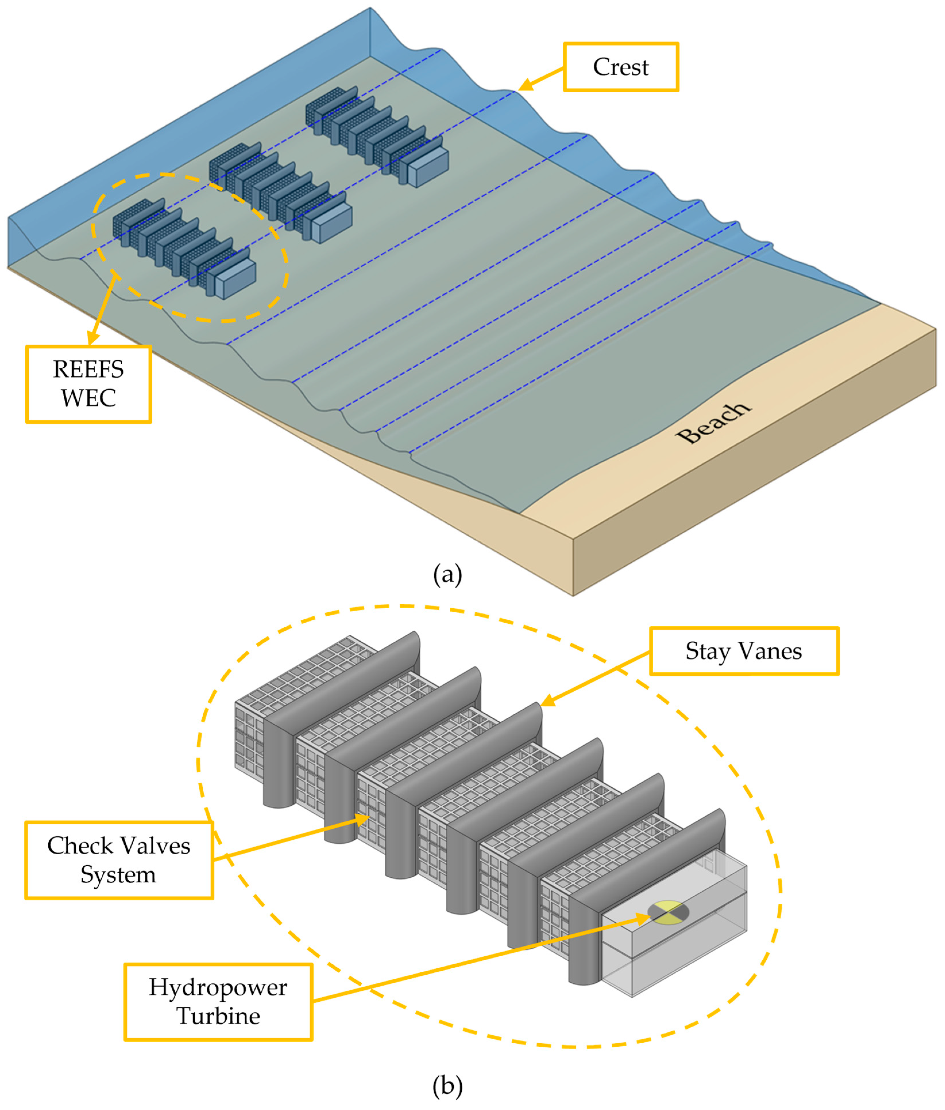
Figure 1. Simplified illustration of the REEFS WEC: (a) nearshore array positioning; (b) schematic constitution.
Inventions 10 00085 g001
Figure 2. Aerial photograph of the Differential Pressure Hydraulic Power Meter (DPHPM) attached to the REEFS lab model (scale 1.5:100), installed on the glass floor of the piston wave-maker flume at the LHWRE of the DCE–UC.
Inventions 10 00085 g002
Figure 3. REEFS wave-to-water power output plots computed by the numerical model and obtained in experimental tests, extrapolated for a prototype with a length of 88 m, a width of 20 m, and a height of 10 m, subjected to waves propagating at 18.3 m water depth. Adapted from [81].
Inventions 10 00085 g003
Figure 4. Photograph of experimental demonstration of wave breaking produced by the REEFS small-scale (3:100) model installed in the piston wavemaker flume of the LHWRE of the DCE of the UC.
Inventions 10 00085 g004
Figure 5. Snapshots of the free surface for an incident wave with a period of T = 0.86 s, wave height of H = 5 cm at water depth of d = 27.5 cm: (a) free surface configuration in CFD model, (b) corresponding free surface configuration in a (1.5:100) small-scale lab model. Adapted from [83].
Inventions 10 00085 g005
Figure 6. Turbine location inside the first (3:100) small-scale REFFS model used for a complete wave-to-wire proof-of-concept (the upper surface was removed to allow inner view of the turbine).
Inventions 10 00085 g006
Figure 7. Snapshot of the complete wave-to-wire proof-of-concept video with the lab (3:100) small-scale REEFS model in the piston wave flume of the LHWRE of the DCE of the UC, available at [85].
Inventions 10 00085 g007
Figure 8. Perspective drawing of the (3:100) small-scale model of the REEFS without support legs and considering transparent stay vanes and membranes to facilitate visualization.
Inventions 10 00085 g008
Figure 9. Snapshot of the wave-to-wire (3:100) small-scale REEFS model proof-of-concept in the piston wave flume of the LHWRE of the DCE of the UC, for a wave period of T = 1.4 s, wave height of H = 8 cm, and water depth d = 43 cm. Version without support legs nor stay vanes, equipped with an opaque membrane.
Inventions 10 00085 g009
Figure 10. Wave-to-water CNWT proof-of-concept of the REEFS WEC. Output snapshots after six wave periods (6T) for time instants (a) t = 6T, (b) t = 6T + T/4, (c) t = 6T + T/2, (d) t = 6T + 3T/4, (1) wave crest, (2) wave trough, (3) outlet velocity vectors, (4) inlet velocity vectors, and (5) streamlines.
Inventions 10 00085 g010
Figure 11. Possible test sites for REEFS WEC (1:10) small-scale model. Adapted from [91]. Lisboa Hayford Gauss IgeoE coordinate system, Tranverse Mercator projection, Lisboa Hayford datum.
Inventions 10 00085 g011
Figure 12. Perspective drawing of the (1:10) small-scale model of the REEFS metallic version and considering transparent membranes to facilitate visualization.
Inventions 10 00085 g012
Figure 13. Illustrative projection of a full-scale REEFS WEC installed on the seabed (concrete version).
Inventions 10 00085 g013
Figure 14. Illustrative projection of a full-scale REEFS WEC nearshore wave farm (concrete version).
Inventions 10 00085 g014
Disclaimer/Publisher’s Note: The statements, opinions and data contained in all publications are solely those of the individual author(s) and contributor(s) and not of MDPI and/or the editor(s). MDPI and/or the editor(s) disclaim responsibility for any injury to people or property resulting from any ideas, methods, instructions or products referred to in the content.