Article

Analytical and Numerical Investigation of Adhesive-Bonded T-Shaped Steel–Concrete Composite Beams for Enhanced Interfacial Performance in Civil Engineering Structures

by
Tahar Hassaine Daouadji
1,2,
Fazilay Abbès
3,
Tayeb Bensatallah
1,2 and
Boussad Abbès
3,*
1
Department of Civil Engineering, Ibn Khaldoun University of Tiaret, Tiaret 14000, Algeria
2
Laboratory of Geomatics and Sustainable Development LGéo2D, University of Tiaret, Tiaret 14000, Algeria
3
Université de Reims Champagne-Ardenne, MATIM, Campus Moulin de la Housse, 51100 Reims, France
*
Author to whom correspondence should be addressed.
Inventions 2025, 10(4), 61; https://doi.org/10.3390/inventions10040061
Submission received: 30 May 2025 / Revised: 19 July 2025 / Accepted: 21 July 2025 / Published: 23 July 2025

Abstract

This study introduces a new method for modeling the nonlinear behavior of adhesively bonded composite steel–concrete T-beam systems. The model characterizes the interfacial behavior between the steel beam and the concrete slab using a strain compatibility approach within the framework of linear elasticity. It captures the nonlinear distribution of shear stresses over the entire depth of the composite section, making it applicable to various material combinations. The approach accounts for both continuous and discontinuous bonding conditions at the bonded steel–concrete interface. The analysis focuses on the top flange of the steel section, using a T-beam configuration commonly employed in bridge construction. This configuration stabilizes slab sliding, making the composite beam rigid, strong, and resistant to deformation. The numerical results demonstrate the advantages of the proposed solution over existing steel beam models and highlight key characteristics at the steel–concrete interface. The theoretical predictions are validated through comparison with existing analytical and experimental results, as well as finite element models, confirming the model’s accuracy and offering a deeper understanding of critical design parameters. The comparison shows excellent agreement between analytical predictions and finite element simulations, with discrepancies ranging from 1.7% to 4%. This research contributes to a better understanding of the mechanical behavior at the interface and supports the design of hybrid steel–concrete structures.

1. Introduction

Adhesive bonding has emerged as a practical alternative to traditional mechanical fastening methods in civil engineering, particularly for the repair and strengthening of steel structural members. This technique involves the elastic bonding of distinct components, typically steel and concrete, to form composite elements capable of resisting bending moments through partial or full interaction. However, such interactions often induces relative slip and differential deflections between the components, which may result in separation phenomena such as uplift at the interface [1,2,3].
In classical composite design, full interaction between components is often assumed, or the interfacial behavior is simplified using idealized models where shear connectors are represented as rigid or elastic springs [4,5]. More recently, fiber-reinforced polymer (FRP) composites have been adopted as an alternative to steel plate reinforcements due to their favorable characteristics, namely low weight, high tensile strength, resistance to corrosion, and long-term durability. Although the mechanical and economic feasibility of using carbon fiber-reinforced polymer (CFRP) plates for strengthening steel members is more limited compared to concrete substrates, CFRP is particularly well-suited for rehabilitating fatigue-prone or pre-damaged steel elements [6,7].
Numerous studies have identified key failure mechanisms in steel–concrete composite members, including local buckling in compression zones, shear-induced buckling, and debonding at the adhesive interface [8,9,10]. Among these, interfacial sliding and delamination due to high shear and normal stresses in the adhesive layer remain the most critical failure modes [11,12]. Accurate prediction of interfacial stress distributions is essential for anticipating such failures. While experimental methods have been used to investigate these stress fields, the complex and highly localized nature of adhesive stresses poses important challenges for experimental validation [13,14].
Recent research has advanced the understanding of steel–concrete composite behavior, particularly in relation to interfacial slip and flexural performance. Karabulut [15,16] explored nonlinear deflection in steel- and GFRP-reinforced concrete beams through combined experimental, theoretical, and machine learning approaches, offering predictive tools for flexural behavior. Daouadji et al. [17,18] investigated interface sliding and bonding modes in I-steel–concrete beams, highlighting the influence of connection continuity and prestressed composite reinforcement on interfacial mechanics. Xie et al. [19] demonstrated the viability of GFRP bars in concrete slabs under aggressive conditions, emphasizing sustainability. Li et al. [20] utilized finite element modeling to simulate the flexural behavior of steel plate–HPC composite beams, showing good correlation with structural responses. Mohammadi Dehnavi et al. [21] addressed connection ductility effects in composite bridges, underlining its role in load distribution. Zeng et al. [22] and Jian et al. [23] provided comprehensive experimental and numerical assessments of interface slip using high-strength connectors and CFRP reinforcement under creep, respectively. Fan et al. [24] proposed slip calculations for beams with clustering studs. Lastly, Peng et al. [25] introduced a design-oriented method to estimate deflections in steel–concrete composite beams considering interface slip.
Table 1 summarizes the scope of the cited studies on bonded steel–concrete composite beams. Compared to existing literature, the present study proposes a closed-form analytical solution for modeling the interfacial sliding behavior of a T-shaped steel–concrete composite beam subjected to external loading. The approach accounts for both continuous and discontinuous adhesive bonding along the interface and introduces a theoretical formulation based on strain compatibility and linear elasticity.
The current study introduces the following new contributions:
-
A closed form analytical model for adhesively bonded beam systems that capture nonlinear shear stress distribution, through strain compatibility, more advanced than prior models based on studs, bolts, or FRP plating (e.g., references [8,10,17,18]).
-
Both continuous and discontinuous adhesive bonding models with different interface conditions (with or without gaps), addressing complexity not covered in existing stud/plate studies.
-
The T-section beam, commonly employed in multisectoral buildings and bridge construction, is selected for the analysis due to its structural relevance and practical implementation, different from I-section beams commonly used in the literature.
The innovation introduced in this study lies in replacing conventional mechanical shear connectors with different adhesive bonding techniques used to join the concrete slab to the steel beam. This innovative approach to bonding steel and concrete components represents a significant advancement in composite beam technology. Adhesively bonded steel–concrete composite beams offer several potential benefits, including reduced stress concentrations at the interface, elimination of on-site welding, and compatibility with prefabricated concrete slabs. As such, this technique is considered a highly promising alternative to conventional mechanically connected composite beams, paving the way for more efficient and sustainable construction practices.
Furthermore, parametric study is handled to investigate the influence of key variables on the performance of the composite system and to validate the development of design recommendations for bonded steel–concrete composite structures to promote their practical use.

2. Materials and Methods: Theoretical Formulation and Solution Procedure

2.1. Solution Method

This section presents the methodology for calculating slip at the steel–concrete interface, addressing the effect of adhesive bonding with continuous and discontinuous connection, using nonlinear beam theory:
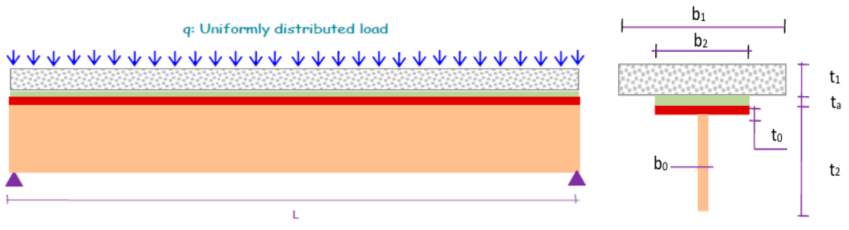
  • Present the assumptions and the static calculation scheme.
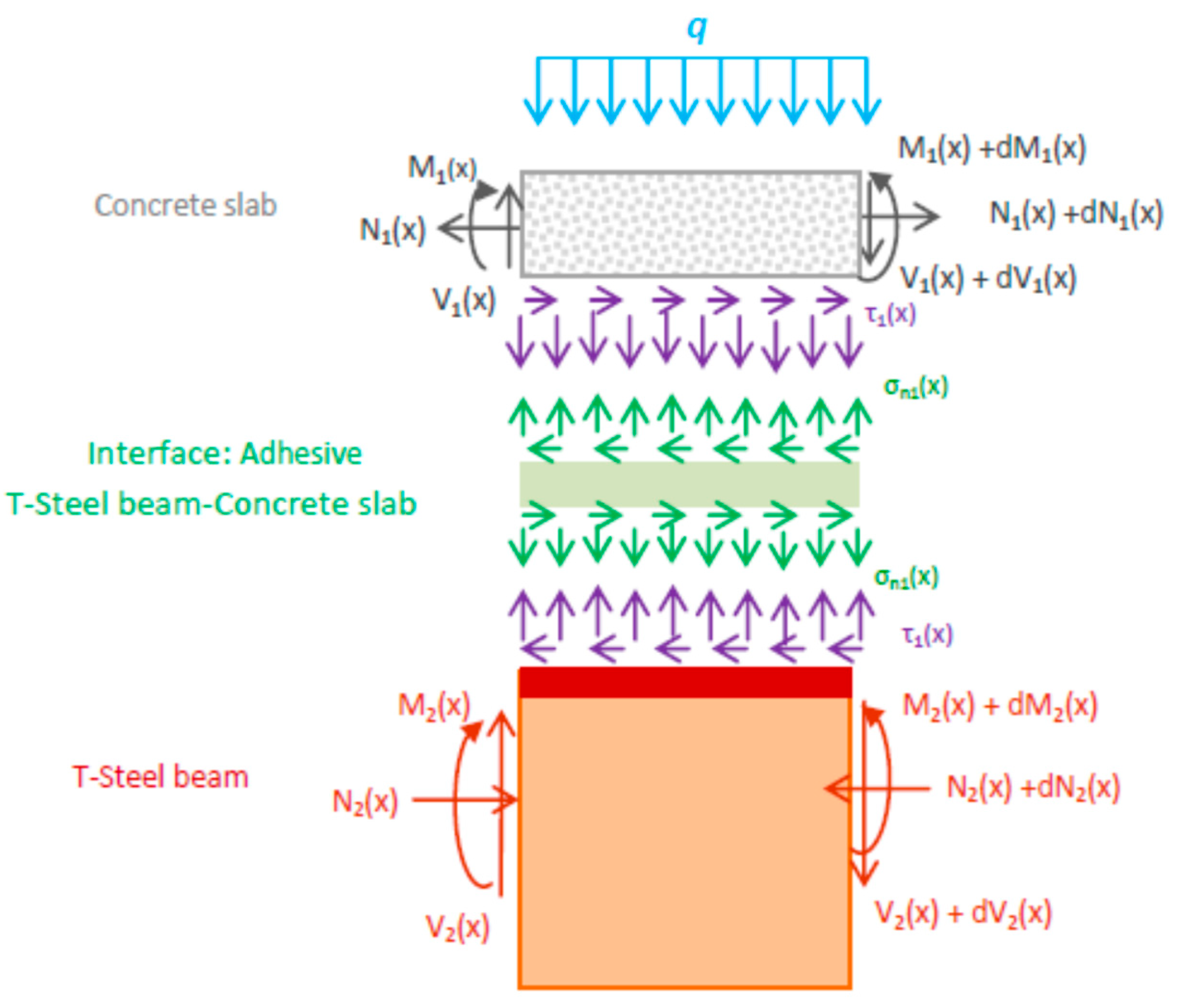
  • Present the internal forces in the infinitesimal element d x of an adhesively bonded T-shaped steel–concrete composite beam to establish the load transfer between the bonds.
  • Present the governing differential equation describing the interfacial shear stress distribution.
  • Formulate the general solutions for loading conditions consisting of either concentrated forces or uniformly distributed loads.
  • Derive the governing differential equation for the interfacial slip strain.
  • Solve for the interfacial slip.

2.2. Assumptions of the New Solution

This study presents an analytical investigation into the interfacial behavior and global response of a T-shaped steel–concrete composite beam connected through an adhesive bonding layer (Figure 1). The analysis focuses on the distribution of transverse shear stresses and associated deformation behavior under mechanical loading, while normal transverse stresses are assumed negligible due to their relatively minor influence in slender beam geometries.
The analytical formulation is built upon a set of simplifying, yet widely accepted, assumptions adapted from Hassaine Daouadji et al. [10], which are enumerated as follows:
-
Linear Elasticity: All constituent materials, the concrete slab, the T-section steel beam, and the adhesive layer, are assumed to behave according to linear elastic constitutive laws.
-
Beam Geometry and Support Conditions: The composite beam is considered to be shallow and simply supported. Consequently, the classical assumption of plane sections remaining plane before and after bending is applied.
-
Interfacial Imperfection: The bond between the concrete slab and the T-steel beam is assumed to be imperfect. As such, relative slip is permitted at the interface, allowing for a realistic simulation of partial interaction behavior.
-
Adhesive Stress Transfer: The adhesive layer is considered to transfer only shear stresses induced by differential deformation between the bonded layers.
-
Adhesive Stress Distribution: Stresses within the adhesive layer are assumed to be uniform across the layer thickness. This assumption is justified when the adhesive thickness is small relative to the beam depth.
-
Global Bending Behavior: The overall deformation of the composite beam is governed by bending behavior, and other deformation modes such as torsion or axial effects are supposed negligible.

2.3. Stress Analysis at the Interface Between Concrete Slab and Steel Beam

The composite steel–concrete beam, comprising a concrete slab, a thin adhesive bonding layer, and a T-shaped steel beam (Figure 2), is analyzed under the assumption of linear elastic material behavior. Each constituent material, concrete, steel, and adhesive, is required to contribute to the overall resistance of the structure by carrying internal forces and moments induced by externally applied transverse loads, denoted as q (distributed) and P (concentrated). The resulting structural deformations reflect the combined effects of flexural and axial strains within the beam components, as well as relative slip at the adhesive interface due to imperfect bonding. The analytical approach accounts for the composite action between the materials and quantifies the degree to which each component participates in resisting the applied loads.
For the sake of analytical simplicity, the following general solutions, describing the interfacial shear stress distribution τ ( x ) along the adhesive layer, are restricted to loading conditions consisting of either concentrated forces, uniformly distributed loads over a portion or the entire span of the beam, or a combination thereof. Under these loading scenarios, the interfacial shear stress for the uniformly distributed load q , and concentrated load P are given by Equations (1) and (2), respectively:
τ x = η q 2 λ L sin h λ L 2 2 λ x sin h λ L 2 + 2 λ cos h λ L 2 sin h λ x L x cos h λ x + L 2 x ,     x     0 x L
τ x = η P 2 sin h λ L 2 cos h λ L 2 sin h λ x cos h λ x + 1 ,     x     0 x L 2
with:
ξ = b 0 ( 3 t a 1 2 ( t 2 2 t 0 ) ( t 2 t 0 ) 2 + t 0 2 ) 6 G 2 t 2 A 2 ,
λ = b 2 y 1 + y 2 y 1 + y 2 + t a 1 E 1 I 1 + E 2 I 2 + 1 E 1 A 1 + 1 E 2 A 2 t a 1 G a 1 + t 1 3 G 1 + t 2 3 G 2 ξ 1 2 ,
η = 1 λ 1 E 1 A 1 + 1 E 2 A 2 t a 1 G a 1 + t 1 3 G 1 + t 2 3 G 2 ξ ,
where t a 1 and t 1 are the thicknesses of the adhesive and the concrete slab, respectively, t 2 is the height of the T-steel beam. G a 1 ,   G 1 and G 2 are the shear moduli of the adhesive, the concrete slab and the T-steel beam, respectively. E 1 and E 2 are the Young’s moduli of the concrete slab and the T-steel beam, respectively. A 1 and A 2 are the cross-sectional area of the concrete slab and the T-steel beam, respectively. I 1 and I 2 are the second moments of area of the concrete slab and the T-steel beam, respectively. y 1 and y 2 are the distances from the bottom of the concrete slab and the top of the steel beam to their respective centroids. t 0 and b 0 are the flange and web thicknesses of the T-steel beam, respectively.

2.4. Slip Distribution Along the Steel–Concrete Interface

The interfacial slip for the uniformly distributed load q , and concentrated load P are given by Equations (6) and (7), respectively:
S x = η q 2 K s λ L sin h λ L 2 2 λ x sin h λ L 2 + 2 λ cos h λ L 2 sin h λ x L x cos h λ x + L 2 x ,
S x = η P 2 K s sin h λ L 2 cos h λ L 2 sin h λ x cos h λ x + 1 ,
where K s = G a 1 t a 1 is the shear stiffness of the adhesive.

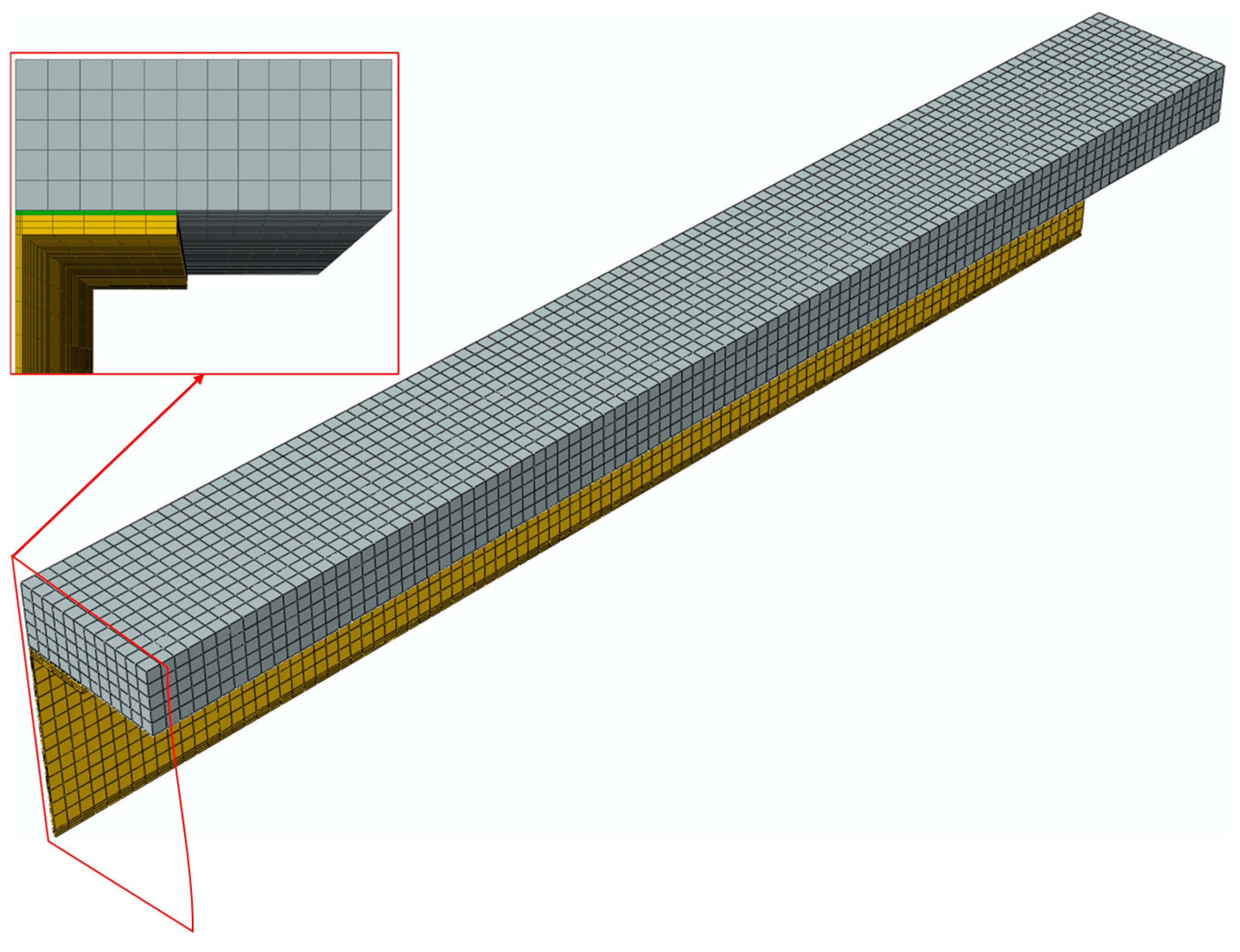
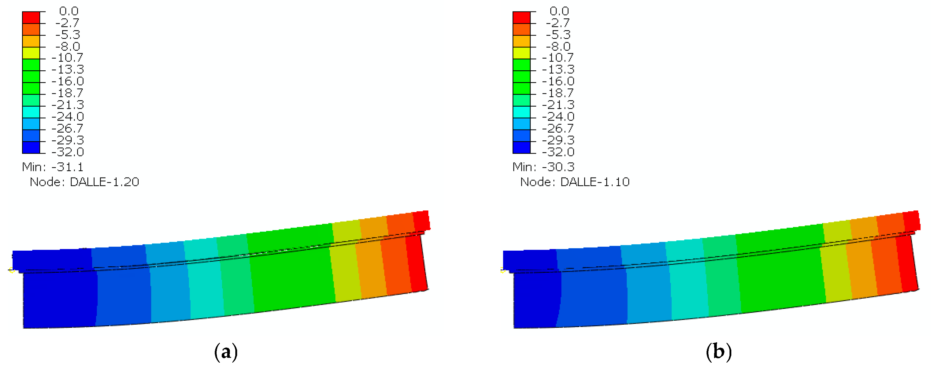
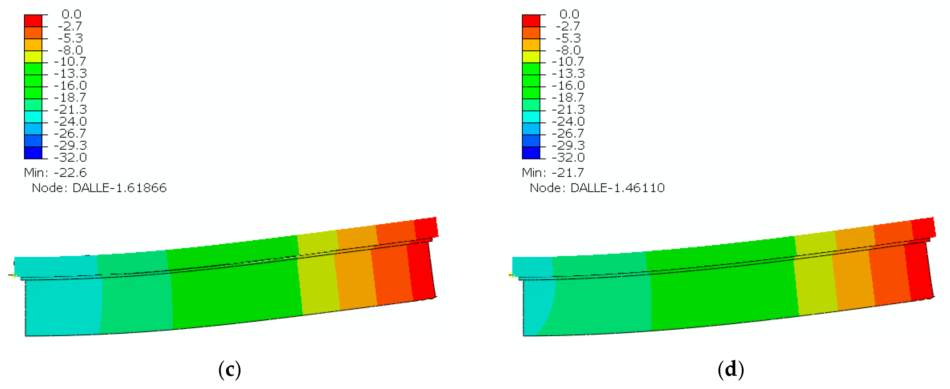
2.5. Finite Element Analysis Method

This study used the ABAQUS 2019 finite element software (Simulia, Velizy-Villacoublay, France) to develop a three-dimensional finite element model to analyze the interface sliding in the composite T-steel–concrete beam. Due to symmetrical considerations, only a quarter of the beam is modeled to reduce computational time. The beam consists of three components: a concrete slab, a T-steel beam, and an adhesive layer. All these components are modeled as solid parts. To ensure the accuracy and reliability of the finite element results, we conducted a mesh sensitivity analysis using different mesh sizes and element types. The mesh refinement study focused on the adhesive layer and the interface region, which are critical for capturing slip behavior accurately. A range of element sizes was tested, and the results were compared in terms of slip prediction, load–displacement response, and stress distribution. Based on this study, three elements through the thickness of both the adhesive layer and the steel girder were chosen as it provided a good balance between computational efficiency and result accuracy. Regarding element type, 3D 8-node hexahedral solid elements (C3D8) for concrete, steel, and adhesive were selected due to their effectiveness in capturing the stress transfer mechanisms across the bonded interface. The optimal finite element mesh used in this study is depicted in Figure 3.
The simulation setup involves applying boundary conditions, as illustrated in Figure 4. Two plans of symmetry are defined, where zero normal displacement is imposed. A concentrated load in midspan or a uniformly distributed load on the top of the composite beam is applied. A simple support condition is applied at the end of the T-beam by constraining the translation in the vertical direction.
To simulate the connection, the adhesive layer was modeled as a continuous bond between the steel girder and concrete slab with perfect bonding assumptions at the interfaces defined by tying the adhesive to concrete slab and T-steel beam. A linear elastic material model was assigned to the concrete slab, the T-steel beam, and the adhesive layer. The solution to the model is calculated using general static stress/displacement analysis available in ABAQUS 2019 Standard version.

3. Results and Discussion

3.1. Materials and Geometry Data

This study employs the proposed models to evaluate the interfacial slip (sliding) within a T-section steel–concrete composite beam connected via adhesive bonding. The composite beam is subjected to either a uniformly distributed or a concentrated loading. The material properties presented in Table 2 were adopted from the literature [26,27] and chosen to reflect values typically used in comparable studies.
Figure 5 presents the detailed dimensions and loading conditions of the adhesive-bonded steel–concrete beam. Figure 6 shows the adhesive bonding configurations of the T-section steel–concrete composite beam, illustrating variations from 25% to 100% of the bonded interface area.

3.2. Validation of the Analytical and the Finite Element Model

Before applying the proposed analytical and numerical models to new configurations, their validity was first established through comparison with existing results from the literature. This validation is based on the experimental study conducted by Bouazaoui et al. [27] and the analytical work developed by Tayeb and Daouadji [26]. The reference composite beam consists of a concrete slab and an I-section steel girder (IPE 220), directly bonded via an adhesive joint, and loaded at its midspan. The beam has a total length of 3480 mm and is simply supported over a span of 3300 mm. The concrete slab is 70 mm thick and 350 mm wide. A detailed description of the experimental setup and material properties is available in Bouazaoui et al. [27].
Figure 7 presents a comparison of the slip–load responses obtained from the present analytical and FEM against both the experimental results and analytical predictions from the literature. The good agreement between the theoretical models and the experimental data confirms the accuracy and robustness of the proposed modeling approach. It is worth noting that the experimental curve exhibits a gradually increasing initial stiffness, unlike the constant stiffness observed in both theoretical and FEM predictions. This nonlinearity at low load levels can be attributed to several physical factors, including progressive engagement of the adhesive interface, surface roughness, micro-settling effects, and possible instrumentation sensitivity. These behaviors, inherent to experimental conditions, are not typically captured in idealized models that assume perfect bonding and time-independent linear elasticity. The experimental results thus highlight real-world complexities that complement and validate the theoretical approach.
In addition, the T-section steel–concrete composite beam demonstrates clearly lower slip values compared to the I-section beam, as evident in both the analytical and numerical simulations. This improvement is primarily due to the increased bonding surface provided by the T-section, which enhances adhesive performance and reduces interfacial slip. As such, the proposed model effectively captures the influence of geometry on slip behavior, offering practical advantages for optimizing bond performance in composite beam systems.

3.3. Parametric Analysis of Factors Influencing Slip in Steel–Concrete Bonds

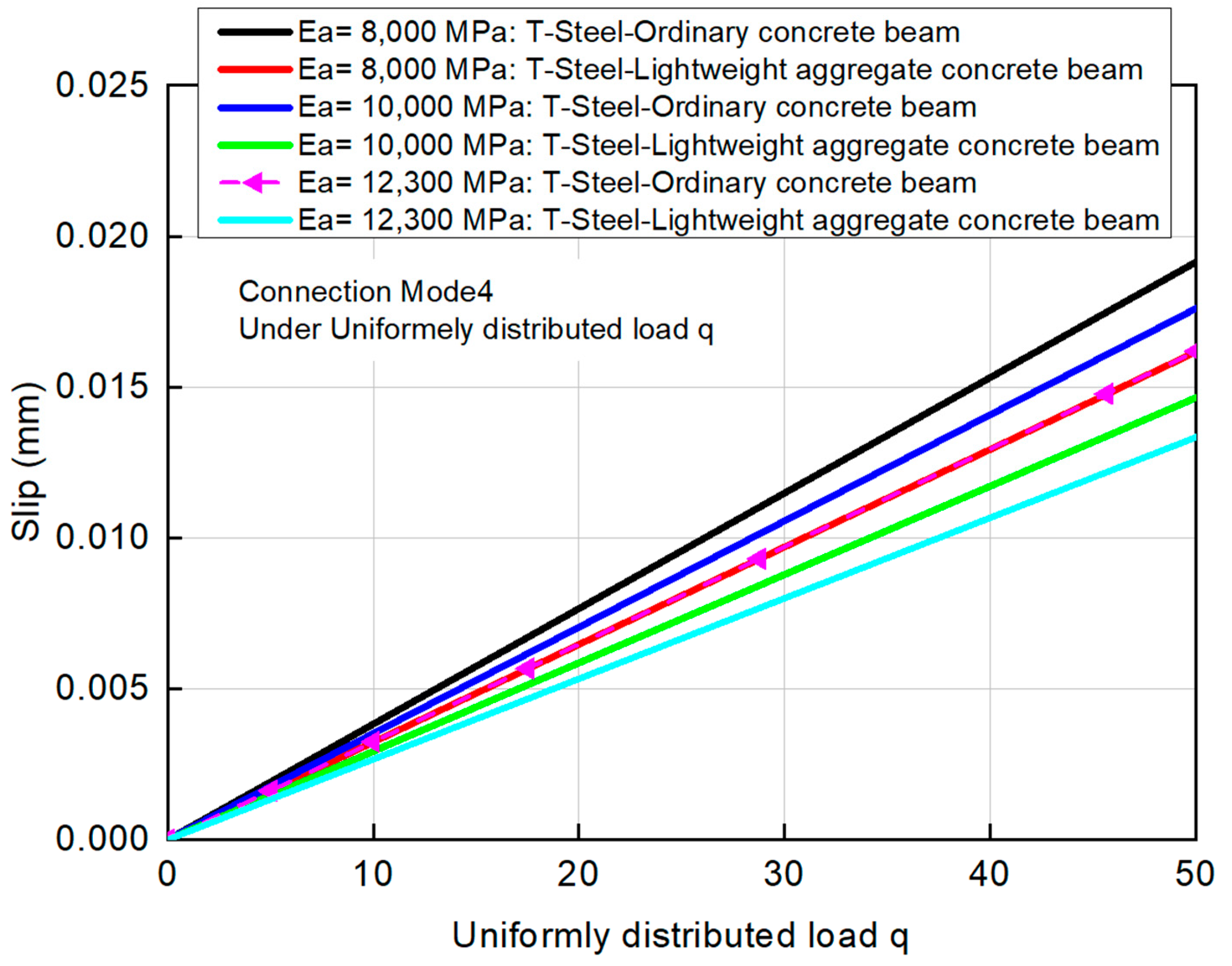
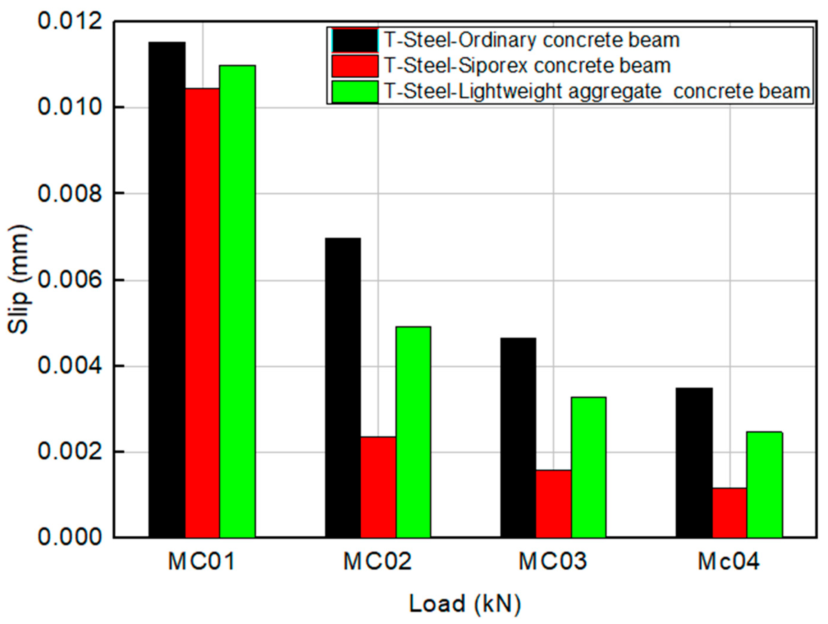
3.3.1. Effect of the Concrete Slab Material on Slip at the Steel–Concrete Interface

The proposed analytical model is validated through a direct comparison with a finite element model (FEM) to assess the influence of concrete’s mechanical properties on the interfacial behavior of composite beams. Specifically, the interface slip between the concrete slab and the T-shaped steel beam is evaluated for both continuous and discontinuous connection configurations under concentrated and uniformly distributed loadings. The corresponding results are presented in Table 3.
It is important to note that this comparison is conducted exclusively between the analytical and numerical models, using identical material parameters obtained from the literature. No experimental data are involved in this correlation. The comparison shows a strong agreement, with differences ranging from 1.7% to 4%, which supports the consistency and accuracy of the analytical approach in capturing the fundamental mechanics of interfacial slip in composite beam systems.
Among all connection modes, a decrease in the elastic modulus of concrete results in an increase in interfacial slip. This tendency reflects the larger deformability of lower-stiffness concrete, which leads to higher relative displacement at the interface. In both loading conditions, discontinuous connection configuration demonstrates the largest interface slip, while continuous connection configuration consistently exhibits the smallest slip. These findings highlight the effectiveness of continuous adhesive joints in promoting continuous and efficient stress transfer, thereby lowering interfacial slip and increasing the overall composite action of the beam.
To enhance the understanding of beam behavior, Figure 8 shows contour plots of vertical displacement under uniformly distributed loading for both the continuous connection configuration (mode 4) and the discontinuous connection configuration (mode 2). These plots are presented for beams made with both ordinary concrete and lightweight aggregate concrete. The maximum beam deflections observed are as follows: Mode 2 (Ordinary Concrete): 22.6 mm, Mode 4 (Ordinary Concrete): 21.7 mm, Mode 2 (Lightweight Aggregate Concrete): 31.1 mm, and Mode 4 (Lightweight Aggregate Concrete): 30.3 mm. The results show that beams with continuous connection (mode 4) consistently exhibit slightly lower vertical displacement than those with discontinuous connection (mode 2), indicating better structural stiffness due to improved interfacial bonding. Additionally, the use of lightweight aggregate concrete leads to higher deflections compared to ordinary concrete, which is attributed to its lower elastic modulus.

3.3.2. Effect of Young’s Modulus of Adhesive on Slip at the Steel–Concrete Interface

The adhesive employed in the composite beam is modeled as a soft, isotropic material characterized by relatively low stiffness. To evaluate the influence of adhesive stiffness on interfacial slip, parametric study was achieved by varying the Young’s modulus of the adhesive layer. The results are presented in Figure 9 and Figure 10 for the T-section steel–concrete composite beam subjected to concentrated and uniformly distributed loads, respectively. These results show a clear trend: increasing the stiffness of the adhesive substantially decreases the interfacial slip between the concrete slab and the steel T-beam.
This decrease in slip becomes especially significant when the concrete has lower stiffness, as in the case of lightweight aggregate concrete, compared to ordinary concrete. The flexibility of the adhesive and concrete in these cases contributes to greater interfacial slip, which in turn weakens the composite interaction between materials.
The use of more compliant adhesives (i.e., with lower Young’s modulus) can be beneficial in reducing interfacial stress concentrations and accommodating localized deformations at the steel–concrete interface. However, this increased flexibility may compromise the composite action and overall structural integrity. This compromise highlights the critical role of adhesive stiffness in attaining an optimal balance between effective stress distribution and structural integration in adhesively bonded steel–concrete composite systems [17].

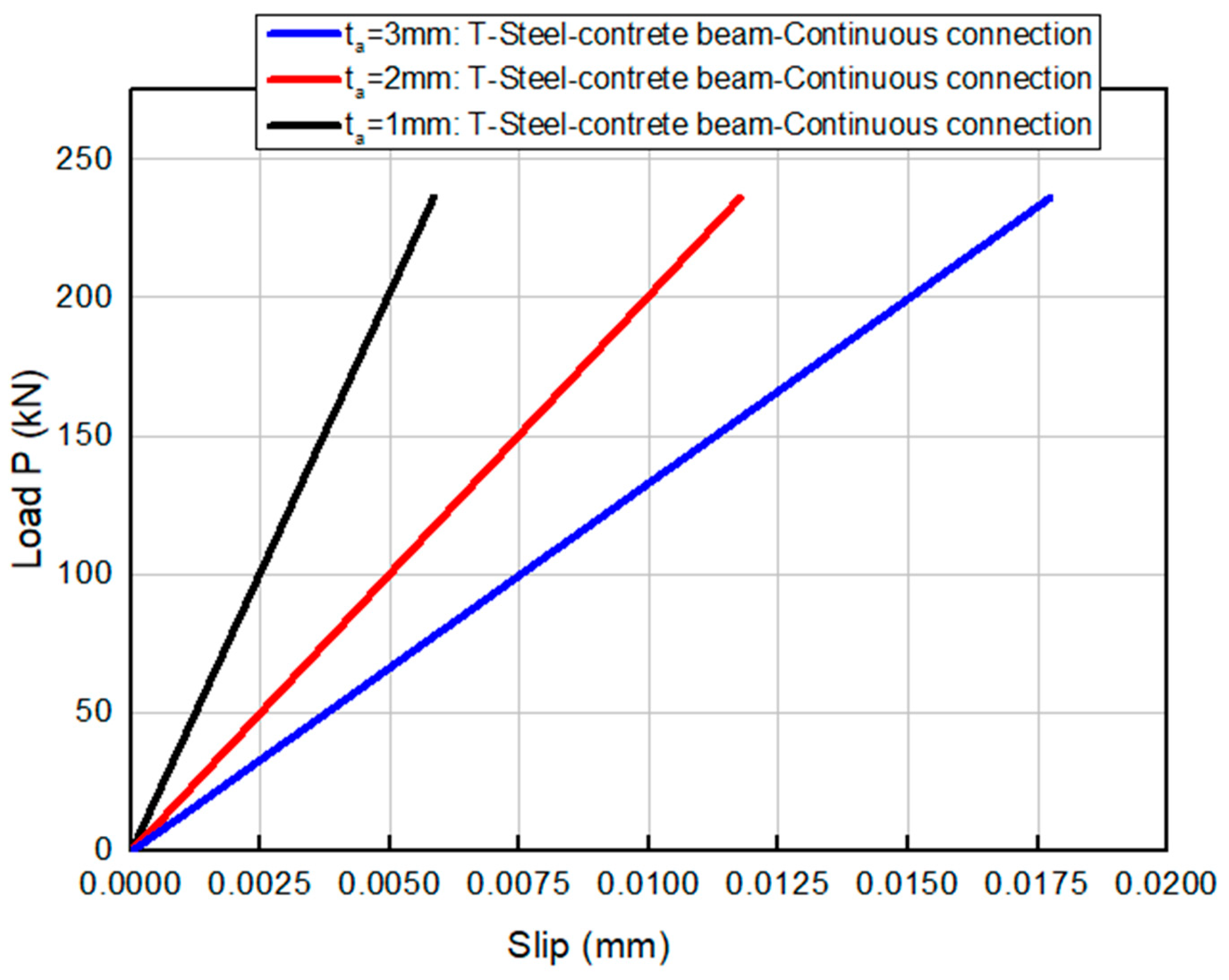
3.3.3. Effect of Adhesive Thickness on Slip at the Steel–Concrete Interface

Figure 11 illustrates the effect of adhesive layer thickness on interfacial slip behavior in a T-section steel–ordinary concrete composite beam. Adhesive thicknesses of 1 mm, 2 mm, and 3 mm were evaluated. An increase in adhesive thickness usually increases the ability of the joint to redistribute stress and mitigate interfacial stress concentrations due to enhanced compliance. However, this increased interfacial compliance also results in larger relative displacements between the adherends, thus increasing shear lag effects and reducing the effectiveness of composite action. Excessive adhesive thickness may lead to reduced load transfer effectiveness and potential instability at the interface. Therefore, to ensure optimal shear transfer and minimize interfacial slip, a minimal adhesive thickness is recommended, promoting higher interfacial stiffness and improved structural integration. Based on this analysis, an adhesive thickness between 1 and 2 mm suggests a good balance between bond strength, slip control, and construction practicality. The 1 mm layer showed the best performance in terms of minimizing slip, while 2 mm may provide more tolerance during application without significant loss of stiffness.

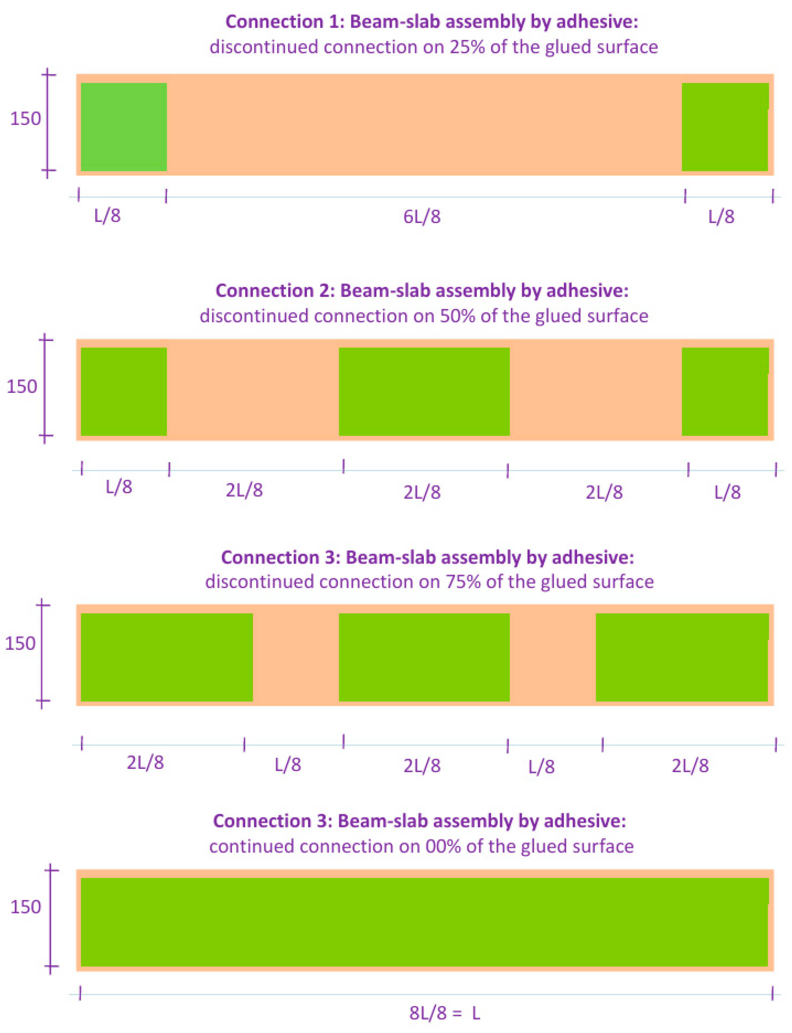
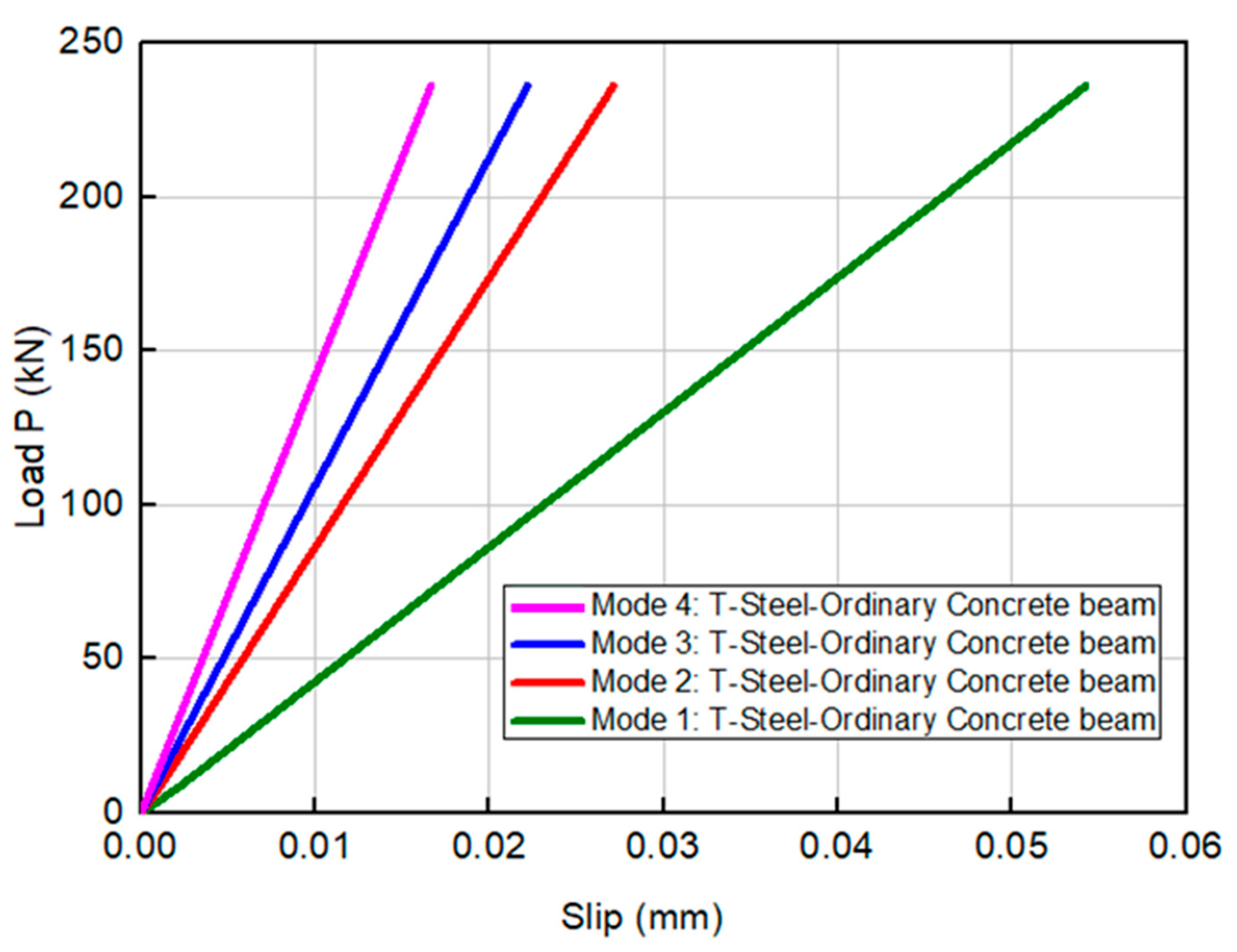
3.3.4. Effect of Connection Mode on Slip at the Steel–Concrete Interface

Figure 12 and Figure 13 illustrate the influence of connection configuration on interfacial slip behavior in a T-section steel–concrete composite beam subjected to both uniformly distributed and concentrated loading. Four adhesive bonding configurations, as defined in Figure 6, were analyzed: Mode 1 (25% bonded area), Mode 2 (50%), Mode 3 (75%), and Mode 4 (100%). The results demonstrate a clear correlation between bonded surface area and interfacial slip: as the effective bonded area decreases, the slip at the steel–concrete interface increases significantly. This behavior is attributed to increased interfacial compliance and exacerbated shear lag effects, which impair the transmission of shear forces across the interface and reduce the degree of composite action. In contrast, Mode 4, representing full adhesive coverage (100%), minimizes relative displacement between the adherends and ensures uniform stress distribution along the interface, thereby enhancing the global stiffness and stability of the composite system. These findings underscore the importance of maximizing bonded surface area in structural applications. Full-surface adhesive bonding is strongly recommended to limit interfacial slip, reduce differential deformation, and maintain the structural integrity of steel–concrete composite elements.

3.3.5. Effect of the Beam Length on Slip at the Steel–Concrete Interface

Table 4 presents the influence of beam span length on interfacial slip in T-section steel–concrete composite beams. Three span lengths were considered: 4 m, 6 m, and 8 m. The results indicate that as the span length increases, the magnitude of interfacial slip becomes more pronounced. This trend is primarily attributed to the increased bending moment and associated curvature in longer beams, which amplify relative displacements at the steel–concrete interface. In longer spans, the adhesive joint is subjected to higher differential strains between the adherends, exacerbating interfacial compliance and intensifying shear lag effects. These phenomena reduce the effectiveness of shear transfer across the bonded interface and compromise the degree of composite action. The findings underscore the importance of accounting for beam slenderness when designing adhesively bonded steel–concrete systems, particularly in applications where minimizing interfacial slip and maximizing structural integration are critical to performance.

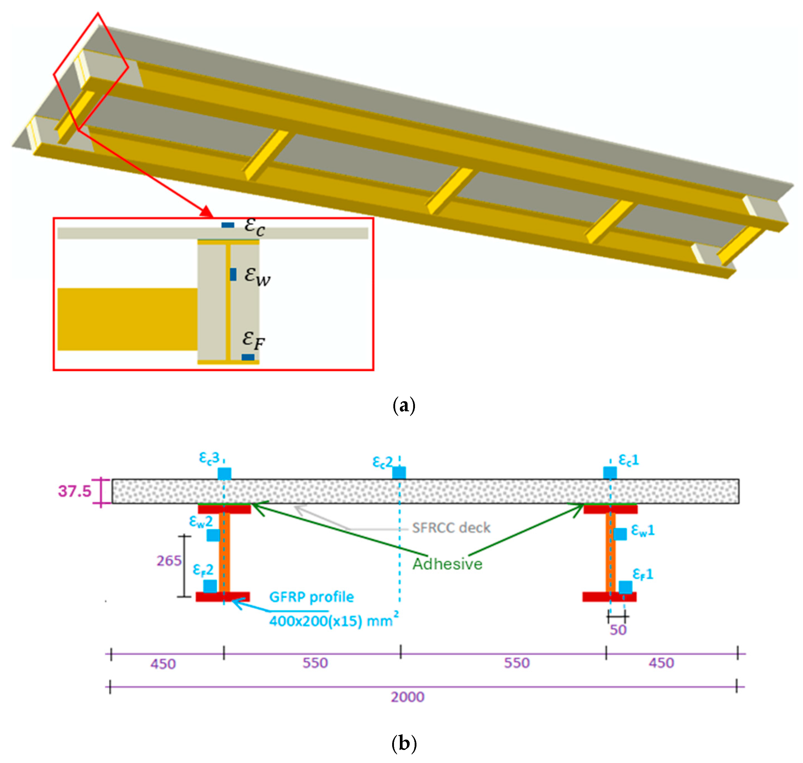
3.4. Case Study: Footbridge

To validate our approach on real study, the hybrid footbridge proposed by Gonilha et al. [28] is analyzed. This case study consists of a simply supported hybrid footbridge, with 11 m of length and 2 m of width. The footbridge is constituted of two pultruded I-shaped glass fiber reinforced polymer (GFRP) girders (400 × 200 (15) mm2) bonded to a 37.5 mm thick deck in steel fiber reinforced self-compacting concrete (SFRSCC). Secondary girders were used to avoid the distortion of the cross-section in case of eccentric loading. These secondary girders, placed at the support, quarter-span and midspan sections, were composed by I-shaped (200 × 100 (10) mm2) GFRP pultruded profiles and connected to the main girders. The 3D geometry, cross-section and strain gauges at midspan of the footbridge are shown in Figure 14.
The footbridge was loaded with uniformly distributed load configurations along the entire span, centered with the deck in a width of 1.20 m with a total load of 106.0 kN.
Firstly, in Table 5, our finite element (FE) results are compared with the experimental and numerical data reported by Gonilha et al. [28] for midspan deflection ( δ ) and axial strains illustrated in Figure 14 ( ε c , ε w , ε F ). The results demonstrate very good agreement between the midspan deflections predicted by our FE model and those measured and computed by Gonilha et al. [28], with relative differences of 4.46% and 1.22%, respectively. Regarding the axial strains, the FE results also show very good correlation with the experimental data reported by Gonilha et al. [28].
Secondly, Figure 15 presents a comparison between the finite element and analytical results for the slip between the deck and the I-shaped GFRP girder. The results indicate very good agreement, with a maximum relative difference of 8.2%. As slip data were not reported in Gonilha et al. [28], a direct comparison was not possible. However, given the validated accuracy of the midspan deflection and axial strain predictions, the proposed analytical model for slip can be considered validated.

4. Conclusions

This study analyzed the mechanical behavior of adhesively bonded T-section steel–concrete composite beams, emphasizing interfacial slip and the influence of key design parameters. The results demonstrate that adhesive stiffness, thickness, bond area, and beam span significantly affect the composite action.
Specifically, higher adhesive stiffness and thinner layers improve stress distribution and reduce slip, enhancing structural performance. In contrast, flexible or thicker adhesives increase interfacial deformation and reduce load transfer efficiency. Full bonding markedly improves global stiffness compared to partial bonding.
These findings provide valuable insights into optimizing the design of adhesive joints in composite systems. Although the conclusions are supported by comparisons with experimental data from the literature on hybrid footbridge, further experimental studies are recommended to fully confirm their applicability across a range of practical scenarios.

Author Contributions

Conceptualization, T.H.D. and B.A.; methodology, T.H.D.; software, B.A. and F.A.; validation, T.B. and F.A.; formal analysis, T.H.D.; investigation, T.B. and F.A.; resources, T.H.D. and B.A.; data curation, B.A.; writing—original draft preparation, T.H.D.; writing—review and editing, B.A.; visualization, F.A. All authors have read and agreed to the published version of the manuscript.

Funding

This research received no external funding.

Data Availability Statement

All data used to support the findings of this study are included within the article.

Conflicts of Interest

The authors declare no conflicts of interest.

References

  1. He, S.; Xu, Y.; Zhong, H.; Mosallam, A.S.; Chen, Z. Investigation on interfacial anti-sliding behavior of high strength steel-UHPC composite beams. Compos. Struct. 2023, 316, 117036. [Google Scholar] [CrossRef]
  2. Cai, M.; Li, W.; Wan, Z.; Sheng, J.; Tan, J.; Ma, C. Cracking control technique for continuous steel–concrete composite girders under negative bending moment. Arch. Civ. Eng. 2023, 69, 239–251. [Google Scholar] [CrossRef]
  3. Chen, Y.; Zhang, Y.; Yu, M.; Hu, X.; He, W.; Qin, K.; Zhu, Y.; Wei, X. Structural Design and Mechanical Behavior Investigation of Steel–Concrete Composite Decks of Narrow-Width Steel Box Composite Bridge. Buildings 2024, 14, 912. [Google Scholar] [CrossRef]
  4. Xin, Q.; Dou, Y.; Li, S. Fatigue Behavior of Prestressed Concrete Beams under Overload. J. Eng. Sci. Technol. Rev. 2017, 10, 124–131. [Google Scholar] [CrossRef]
  5. Berthet, J.F.; Yurtdas, I.; Delmas, Y.; Li, A. Evaluation of the adhesion resistance between steel and concrete by push out test. Int. J. Adhes. Adhes. 2011, 31, 75–83. [Google Scholar] [CrossRef]
  6. Wang, Y.H.; Yu, J.; Liu, J.P.; Zhou, B.X.; Chen, Y.F. Experimental study on assembled monolithic steel-prestressed concrete composite beam in negative moment. J. Constr. Steel Res. 2020, 167, 105667. [Google Scholar] [CrossRef]
  7. Henriques, D.; Gonçalves, R.; Sousa, C.; Camotim, D. GBT-based time-dependent analysis of steel–concrete composite beams including shear lag and concrete cracking effects. Thin-Walled Struct. 2020, 150, 106706. [Google Scholar] [CrossRef]
  8. Bensatallah, T.; Daouadji, T.H.; Abderezak, R.; Tounsi, A. Structural bonding for civil engineering structures: New model of composite I-steel–concrete beam strengthened with CFRP plate. Steel Compos. Struct. 2021, 41, 417–435. [Google Scholar] [CrossRef]
  9. Tounsi, A.; Daouadji, T.H.; Benyoucef, S. Interfacial stresses in FRP-plated RC beams: Effect of adherend shear deformations. Int. J. Adhes. Adhes. 2009, 29, 343–351. [Google Scholar] [CrossRef]
  10. Tahar, H.D.; Boussad, A.; Abderezak, R.; Rabia, B.; Fazilay, A.; Belkacem, A. Flexural behaviour of steel beams reinforced by carbon fibre reinforced polymer: Experimental and numerical study. Struct. Eng. Mech. 2019, 72, 409–420. [Google Scholar] [CrossRef]
  11. Xue, W.; Ding, M.; Wang, H.; Luo, Z. Static behavior and theoretical model of stud shear connectors. J. Bridge Eng. 2008, 13, 623–634. [Google Scholar] [CrossRef]
  12. Tang, L. Experimental study on HSS-concrete composite beams. J. Build. Struct. 2009, 30, 64–69. Available online: https://en.cnki.com.cn/Article_en/CJFDTOTAL-JZJB200902007.htm (accessed on 11 April 2025).
  13. Hegger, J.; Döinghaus, P. High performance steel and high-performance concrete in composite structures. In Composite Construction in Steel and Concrete IV; American Society of Civil Engineers: Reston, VA, USA, 2000; pp. 891–902. [Google Scholar]
  14. Du, H.; Hu, X.; Shi, D.; Xue, W. Flexural performance of composite beams using high-strength steel and high-strength concrete. Int. J. Steel Struct. 2021, 22, 27–41. [Google Scholar] [CrossRef]
  15. Karabulut, M. Nonlinear Load-Deflection Analysis of Steel Rebar-Reinforced Concrete Beams: Experimental, Theoretical and Machine Learning Analysis. Buildings 2025, 15, 432. [Google Scholar] [CrossRef]
  16. Karabulut, M. Machine learning-driven flexural performance prediction and experimental investigation of glass fiber-reinforced polymer bar-reinforced concrete beams. Polymers 2025, 17, 713. [Google Scholar] [CrossRef]
  17. Daouadji, T.H.; Abbès, B.; Bensatallah, T.; Abbès, F. Analysis of Interface Sliding in a Composite I-Steel–Concrete Beam Reinforced by a Composite Material Plate: The Effect of Concrete–Steel Connection Modes. J. Compos. Sci. 2025, 9, 273. [Google Scholar] [CrossRef]
  18. Daouadji, T.H.; Abderezak, R.; Rabia, B. Analysis of mechanical performance of continuous steel beams with variable section bonded by a prestressed composite plate. Steel Compos. Struct. 2024, 50, 183–199. [Google Scholar] [CrossRef]
  19. Xie, F.; Tian, W.; Li, S.; Diez, P.; Zlotnik, S.; Gonzalez, A.G. Experimental study on the structural performance of glass-fiber-reinforced concrete slabs reinforced with glass-fiber-reinforced polymer (GFRP) bars: A sustainable alternative to steel in challenging environments. Polymers 2025, 17, 1068. [Google Scholar] [CrossRef]
  20. Li, J.P.; Zhang, L.Y.; Zhu, Y.J.; Zhao, G.; Liu, F.Z.; Zhang, T. Finite Element Analysis of the Flexural Behavior of Steel Plate–High-Performance Concrete (HPC) Slab and Beam Composite Structures. Buildings 2024, 15, 27. [Google Scholar] [CrossRef]
  21. Mohammadi Dehnavi, M.M.; De Angelis, A.; Pecce, M.R. The effect of connection ductility on Composite steel–concrete bridges. Appl. Sci. 2024, 14, 963. [Google Scholar] [CrossRef]
  22. Zeng, W.; Fan, L.; Chen, F.; Zhu, S. Theoretical, experimental, and numerical simulation studies on interface slip in steel–concrete composite continuous beams with high-strength bolted connectors. Structures 2025, 71, 108126. [Google Scholar] [CrossRef]
  23. Jian, X.; Zhang, N.; Liu, H.; Zhao, Z.; Lei, M.; Chen, Z. Interface slip of steel–concrete composite beams reinforced with CFRP sheet under creep effect. Sci. Rep. 2022, 12, 22375. [Google Scholar] [CrossRef]
  24. Fan, L.; Xu, Y.M.; Tan, Y. Interface slip calculation of prefabricated steel–concrete composite beams with clustering studs. J. Jilin Univ. Eng. Technol. Ed. 2023, 53, 2533–2541. [Google Scholar] [CrossRef]
  25. Peng, F.; Xue, W.; Bai, L.; Du, M. Design Approach for Short-Term Deflection of Simple and Continuous Steel–Concrete Composite Beams Considering Interface Slip. J. Struct. Eng. 2025, 151, 04025072. [Google Scholar] [CrossRef]
  26. Tayeb, B.; Daouadji, T.H. Improved analytical solution for slip and interfacial stress in composite steel–concrete beam bonded with an adhesive. Adv. Mater. Res. 2020, 9, 133–153. [Google Scholar] [CrossRef]
  27. Bouazaoui, L.; Perrenot, G.; Delmas, Y.; Li, A. Experimental study of bonded steel concrete composite structures. J. Constr. Steel Res. 2007, 63, 1268–1278. [Google Scholar] [CrossRef]
  28. Gonilha, J.A.; Barros, J.; Correia, J.R.; Sena-Cruz, J.; Branco, F.A.; Ramos, L.F.; Gonçalves, D.; Alvim, M.R.; Santos, T. Static, dynamic and creep behaviour of a full-scale GFRP-SFRSCC hybrid footbridge. Compos. Struct. 2014, 118, 496–509. [Google Scholar] [CrossRef]
Figure 1. Simply supported composite T-steel–concrete beam.
Inventions 10 00061 g001
Figure 2. Internal force distribution in an infinitesimal element of an adhesively bonded T-shaped steel–concrete composite beam.
Inventions 10 00061 g002
Figure 3. Finite element mesh.
Inventions 10 00061 g003
Figure 4. Finite element boundary conditions.
Inventions 10 00061 g004
Figure 5. Geometric characteristics of T-steel–concrete beam under: (a) uniformly distributed loading; (b) concentrated loading.
Inventions 10 00061 g005
Figure 6. Adhesive bonding configurations of the T-section steel–concrete composite beam, illustrating variations from 25% to 100% of the bonded interface area.
Inventions 10 00061 g006
Figure 7. Comparison of load–slip curves of a simply supported composite steel–concrete beam bonded with an adhesive, with experimental model data based on Bouazaoui et al., 2007 [27] and analytical model data based on Tayeb and Daouadji, 2020 [26].
Inventions 10 00061 g007
Figure 8. Contour plots of vertical displacement under uniformly distributed loading for (a) Mode 2 (ordinary concrete). (b) Mode 2 (lightweight aggregate concrete). (c) Mode 4 (ordinary concrete). (d) Mode 4 (lightweight aggregate concrete).
Inventions 10 00061 g008aInventions 10 00061 g008b
Figure 9. Effect of adhesive Young’s modulus on the load–slip behavior of a T-section steel–concrete composite beam subjected to concentrated load.
Inventions 10 00061 g009
Figure 10. Effect of adhesive Young’s modulus on the load–slip behavior of a T-section steel–concrete composite beam subjected to uniformly distributed load.
Inventions 10 00061 g010
Figure 11. Effect of adhesive thickness on the load–slip behavior of a T-section steel–concrete composite beam.
Inventions 10 00061 g011
Figure 12. Effect of adhesive connection mode on the load–slip behavior of a T-section steel–concrete composite beam subjected to uniformly distributed load.
Inventions 10 00061 g012
Figure 13. Effect of adhesive connection mode on the load–slip behavior of a T-section steel–concrete composite beam subjected to concentrated load.
Inventions 10 00061 g013
Figure 14. Geometry of the footbridge: (a) 3D representation. (b) Cross-section and strain gauges at midspan.
Inventions 10 00061 g014
Figure 15. Slip behavior between the deck and the I-shaped GFRP girder.
Inventions 10 00061 g015
Table 1. Summary of the literature on bonded steel–concrete composite beams.
ReferencesScope
[1,5,6,12,14,22,23]Focus on experimental tests to characterize steel–concrete interface adhesion, sliding/slip behavior, and bond strength under various loading and reinforcement conditions.
[7,9,11,14,20,22,24,25]Development of analytical, numerical, or finite-element models to predict interface slip, load transfer, flexural behavior, and connector performance in composite beams.
[8,9,10,17,23]Studies involving the use of fiber-reinforced polymer (FRP) materials or composite plates to strengthen steel–concrete beams and analyze interfacial stress improvements.
[3,4,6,10,14,15,16,18,21]Experimental and/or theoretical analysis of flexural capacity, crack control, fatigue, and ductility of steel–concrete composite beams, including machine learning approaches for behavior prediction.
[1,13,14,19]Research on the use of high-performance steel, UHPC, or glass-fiber-reinforced polymer composites to improve structural performance and sustainability.
[2,6]Techniques and experimental studies focused on controlling cracking under negative bending moments in composite girders and beams.
[18,22,25]Studies on interface slip and structural response in continuous composite beams or those with variable cross-sections, often incorporating prestressing or bolted connectors.
Table 2. Material properties.
MaterialsYoung’s Modulus (MPa)Poisson Ratio
Concrete slabOrdinary concrete E 1 = 36,600 ν 1 = 0.2
Siporex concrete E 1 = 2800 ν 1 = 0.2
Lightweight aggregate concrete E 1 = 10,000 ν 1 = 0.2
AdhesiveAdhesive between concrete slab and steel beam E a 1 = 12,300 ν a 1 = 0.34
T-shaped steel beamSteel E 2 = 200,000 ν 2 = 0.3
Table 3. Comparison of finite element and analytical results for evaluating slip in a T-section steel–concrete composite beam.
LoadConnection ModeSolutionOrdinary
Concrete
Siporex
Concrete
Lightweight Aggregate Concrete
Concentrated load P = 200 kNDiscontinuousFEM0.01830.03550.0264
Analytical0.017980.034720.02588
ContinuousFEM0.01780.03400.0240
Analytical0.018510.035360.02496
Uniformly distributed load q = 50 kN/mLDiscontinuousFEM0.03750.07160.0535
Analytical0.038430.07340.0548
ContinuousFEM0.03360.07020.0504
Analytical0.034440.071950.05166
Table 4. Effect of the beam length on slip at the steel–concrete interface.
Length (mm)q = 100 kN/mL
40000.04156
60000.06234
80000.08313
Table 5. Comparison of midspan deflection and axial strains.
δ (mm) ε c (μm/m) ε w (μm/m) ε F (μm/m)
Test (Gonilha et al. [28])38.07−1903201102
FEM (Gonilha et al. [28])36.82−1884251161
FEM (Present study)36.37−1813341029
Disclaimer/Publisher’s Note: The statements, opinions and data contained in all publications are solely those of the individual author(s) and contributor(s) and not of MDPI and/or the editor(s). MDPI and/or the editor(s) disclaim responsibility for any injury to people or property resulting from any ideas, methods, instructions or products referred to in the content.

