Article

Novel Heat Exchangers with Cross-Runners for Air and Water Cooling

1
Department of Mechanical Engineering, Chienkuo Technology University, 50094 Changhua, Taiwan
2
Department of Energy Engineering, National United University, 36003 Miaoli, Taiwan
3
Liquid Cooler Technology Co., LTD., 24142 New Taipei, Taiwan
*
Author to whom correspondence should be addressed.
Inventions 2016, 1(2), 10; https://doi.org/10.3390/inventions1020010
Submission received: 15 March 2016 / Revised: 6 May 2016 / Accepted: 12 May 2016 / Published: 23 May 2016

Abstract

:
This work experimentally investigated the pressure drops and heat transfer characteristics of cross-runner heat exchangers. Three kinds of configurations employed were, (1) the aluminum alloy heat exchanger with a staggered rectangular-fin array (Model A); (2) the aluminum alloy heat exchanger with a staggered round pin fin array (Model B); and (3) the copper heat exchanger sintered by multiple copper sheets with rectangular punched holes forming cross-runners (Model C). The results indicate that increasing heat-transfer area (AHT) and decreasing porosity (ε) of the heat exchanger significantly enhanced the heat transfer capacity of the cross-runner heat exchanger, but also increased flow resistance. At the same pumping power for the air-cooled heat transfer experiment, the Nu of Model C was 2.27 and 1.67 times that of Models A and B respectively. Additionally, this study proposed the semi-empirical correlations of dimensionless pressure drop and Nusselt number in terms of Reynolds number for air-cooling measurements. Finally, the feasibility of using the present cross-runner heat exchangers for an instantaneous water heater was also investigated according to the water-cooled heat transfer experiment and the results showed great commercial potential of Model C.

1. Introduction

Heat exchangers are widely applied to many industrial applications, including heating in boilers and cooling in condensers. The small heat exchangers, such as finned heat sinks, are also popular ones for instantaneous water heaters and 3C cooling devices. Since that the modern 3C electronic chips are increased in the computing speeds and narrowed in the dimensions, the operating temperature of such chips goes up greatly. In order to maintain a normal operating temperature for the modern chips, the total heat exchange surface area and the structural complexity of the heat sink installed on the chips are increased. Therefore, the overall convection heat transfer between the fluid and fin matrix can be enhanced effectively due to the increase of heat dispersion area and the improvement of fluid turbulence. The result is better reliability and a longer service life for electronic components and machinery. This kind of finned heat sink is easily manufactured and inexpensive. The key factors that influence the performance of finned heat sink include the fluid velocity, the thermal properties of the fluid and the fins, the height and cross-sectional shape of the fins, the arrangement and relative pitch for the fin array, the bypass effect, and so on.
Many studies have been made for the effects of all these factors on the heat transfer of fin arrays. Vanfossen [1], as well as Brigham and Vanfossen [2], discussed the heat transfer of staggered pin-fin arrays, and indicated that the long pin-fin (H/d = 4) transferred heat better than short ones (H/d = 1/2 and 2). The heat transfer capacity of eight-row pin-fins was slightly higher than that of four-row pin-fins, and the pin-fin surface heat transfer coefficient was about 35% higher than the end-wall surface. Metzger et al. [3] indicated that the heat transfer capacity of oblique pin-fins was 20% higher than that of vertical pin-fins, but the pressure drop was doubled. In addition, they evaluated the pin-fin surface heat transfer coefficient at about two times that of the end-wall surface. Zukauskas and Ulinskas [4] established empirical correction equations for the heat transfer and pressure drop of in-line and staggered round pin arrays. Armstrong and Winstanley [5] made retrospective comments on the effect of pin-fin height and pitch on the heat transfer and flow resistance. Jubran et al. [6] indicated that the optimum pin-fin pitch was 2.5 times the pin-fin diameter. Tahat et al. [7,8] found that the optimum pitch of in-line pin-fin array was 1.3 times the pin-fin diameter, and the optimum pitch for a staggered pin-fin array was 2.2 times the pin-fin diameter. Babus’Haq et al. [9] suggested that the optimum transverse pitch of a pin-fin array was 2.04 times the pin-fin diameter, and the optimum longitudinal pitch was 1.63~1.95 times the pin-fin diameter. Sara et al. [10,11] discussed the heat transfer and pressure drop characteristics of an in-line pin-fin array in a channel with a fixed transverse pin-fin pitch and a variable longitudinal pitch. Wang et al. [12] reviewed shell-and-tube heat exchangers. They indicated that the multi-objectives optimization for air-cooled heat exchangers should consider the heat transfer, pumper power, space usage and other economic influence factors. Chen et al. [13] carried out the optimizations of H- and X-shaped heat exchangers by taking the maximum ratio of the dimensionless heat transfer rate to the dimensionless total pumping power as optimization objective. They reported that the performance of the heat exchanger with X-shaped structure was superior to that with H-shaped structure. Li et al. [14] experimentally investigated the effects of material thermal conductivity and thermal boundary conditions (i.e., conjugate and convective boundary conditions) on the conjugate heat transfer performance of pin fin arrays. They indicated that thermal conductivity could strongly influence the heat transfer performance. The thermal gradient along the wall thickness increased as the material thermal conductivity dropped; the temperature difference between convective and conjugate problems also raised. It would be not desirable in cooling design. Jadhav and Balaji [15] investigated the fluid flow and the heat transfer behaviors of a vertical channel with detached pin-fin arrays arranged in staggered manner on two opposite end walls. Their results found that the volume ratio of pin fins to total channel was the most dominating variable for both the pressure drop and the thermal resistance. They also perform a multi-objective optimization by using the multi-objective evolutionary algorithm to minimize the thermal resistance and the pumping power simultaneously.
Apart from finned heat sink, metallic porous media are also employed as heat exchangers. Metal foam, with high permeability, is one of the popular porous materials. Schampheleire et al. [16] reviewed the available methods to study thermal applications with open-cell metal foam. Chen and Wang [17] experimentally studied the heat transfer of the heat sink by employing non-uniform arrangements of metal foams for liquid cooling. It is found that the thermal resistance could be reduced by more than 62% as compared to that of empty plate design. For a given pumping power, the optimal metal-foam arrangement to have the best heat transfer performance is that the PPI (pores per inch) of metal foam descending from the inlet to the outlet of the heat sink. Abadi et al. [18] experimental explored the single-phase heat transfer mechanism of R245fa refrigerant in a metal-foam-filled plate heat exchanger. Their result demonstrated that, compared to the empty-channel heat exchanger, inserting 60-PPI metal foam promoted the heat transfer coefficient by up to 5.1 times. However, it also had the greatest pressure drop, which was 5.7 times that of an empty-channel heat exchanger. Metal foams not only extend lots of heat dispersion areas, but also increase fluid turbulence significantly, enhancing the total heat transfer capacity efficiently.
However, the porous structure reduces the effective thermal conductivity simultaneously. Inserting a metal core or fins into metal foams is one of the remedy methods to increase the effective thermal conductivity. It is a benefit to the conjugate heat transfer. Feng et al. [19] presents a study on finned metal foam (FMF) and metal foam (MF) heat sinks under impinging air jet cooling. They reported that the heat transfer of FMF heat sinks could be 1.5–2.8 times that of the MF heat sinks. Shih et al. [20] experimentally investigated the heat transfer characteristics of aluminum-foam heat sinks with the solid aluminum core under impinging-jet flow conditions. The Nusselt number of the aluminum-foam heat sink with a solid aluminum core reached a maximum of approximately 2.2 times that of the sample without a core.
This paper offers three designs of cross-runner heat exchangers. As shown in Figure 1, there are regularly-staggered fins in a rectangular channel to form multiple cross-runners, so that the heat exchange area per unit volume is greatly enlarged, and the fluid is separated and merged continuously in the cross-runners. This increases flow turbulence to further enhance heat transfer. Three kinds of configurations employed were, (1) the aluminum alloy heat exchanger with a staggered rectangular-fin array (Model A); (2) the aluminum alloy heat exchanger with a staggered round pin-fin array (Model B); and (3) the copper heat exchanger sintered by multiple copper sheets with rectangular punched holes forming cross-runners (Model C). Among the present three configurations, Model C has the very similar open-cell structure like metal foam, but with high effective thermal conductivity. These cross-runner heat exchangers were manufactured and an air-cooled heat transfer experimental platform was built. The pressure drop characteristics and heat transfer capacity of each of these three types of cross-runner heat exchangers were investigated. The feasibility of using a cross-runner heat exchanger for instantaneous water heating was also examined.

2. Tests of Heat-Transfer Performance

Two experimental setups were used herein. One is for air-cooling measurement and the other is for water-cooling measurements. They are described as follows.

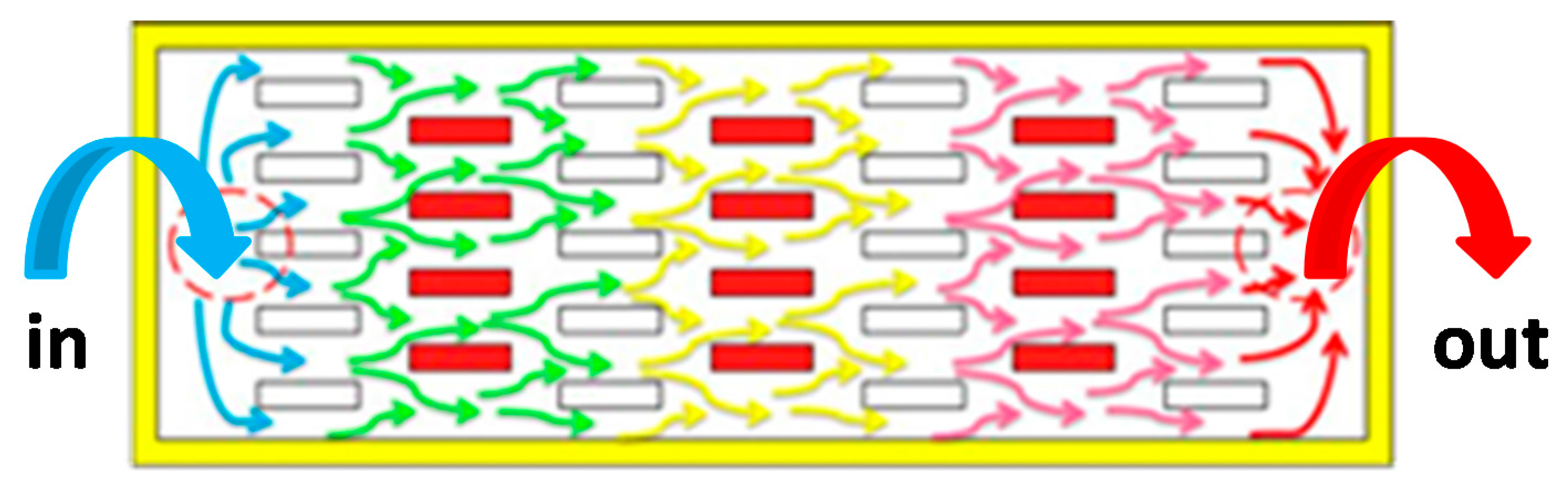
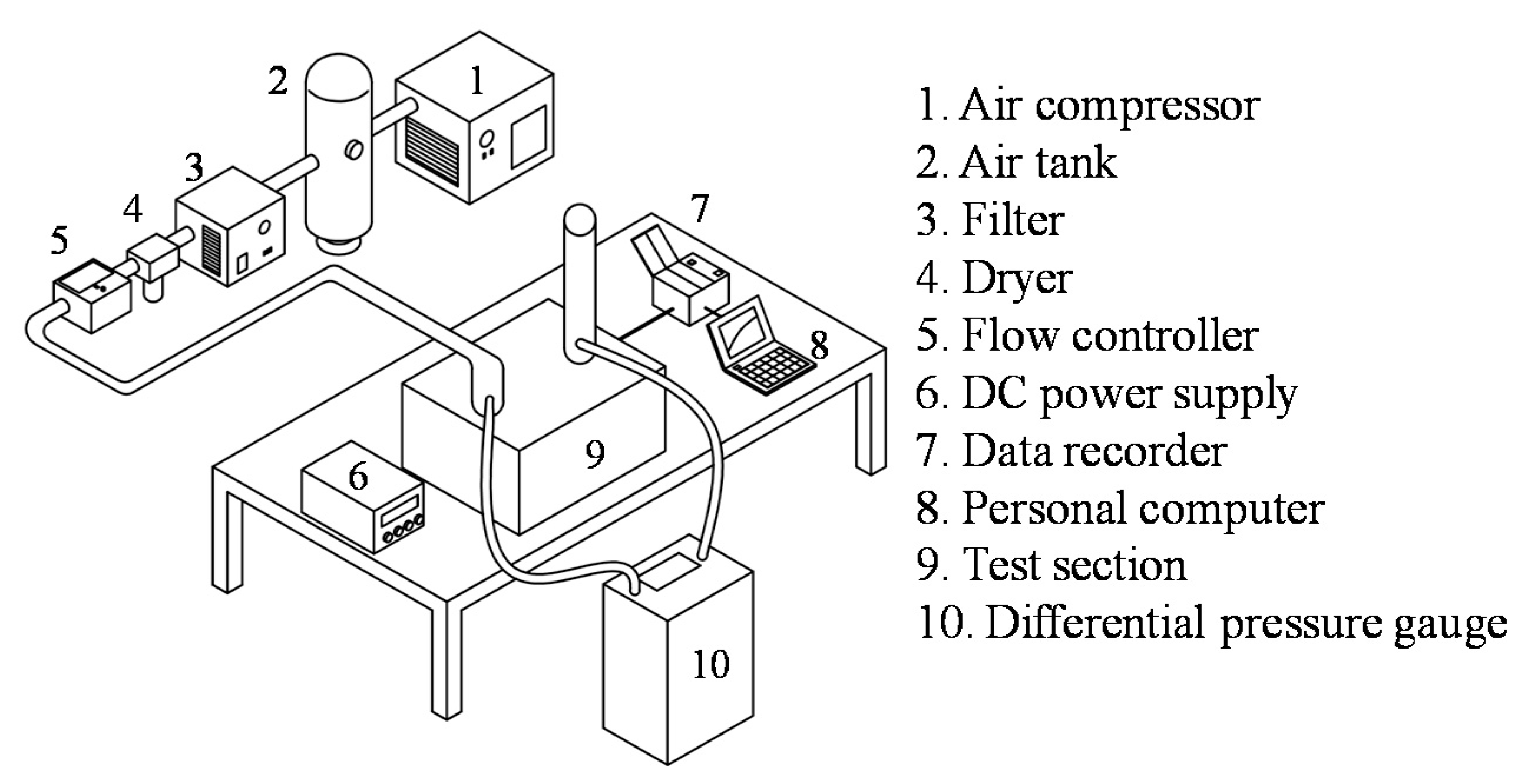
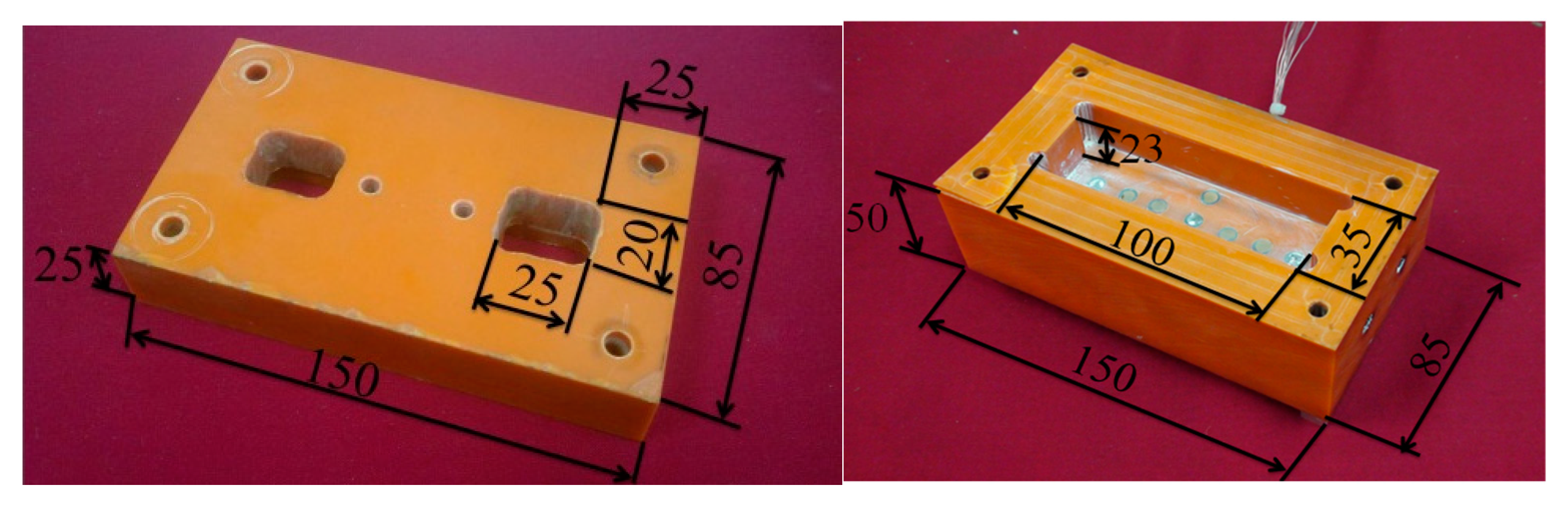
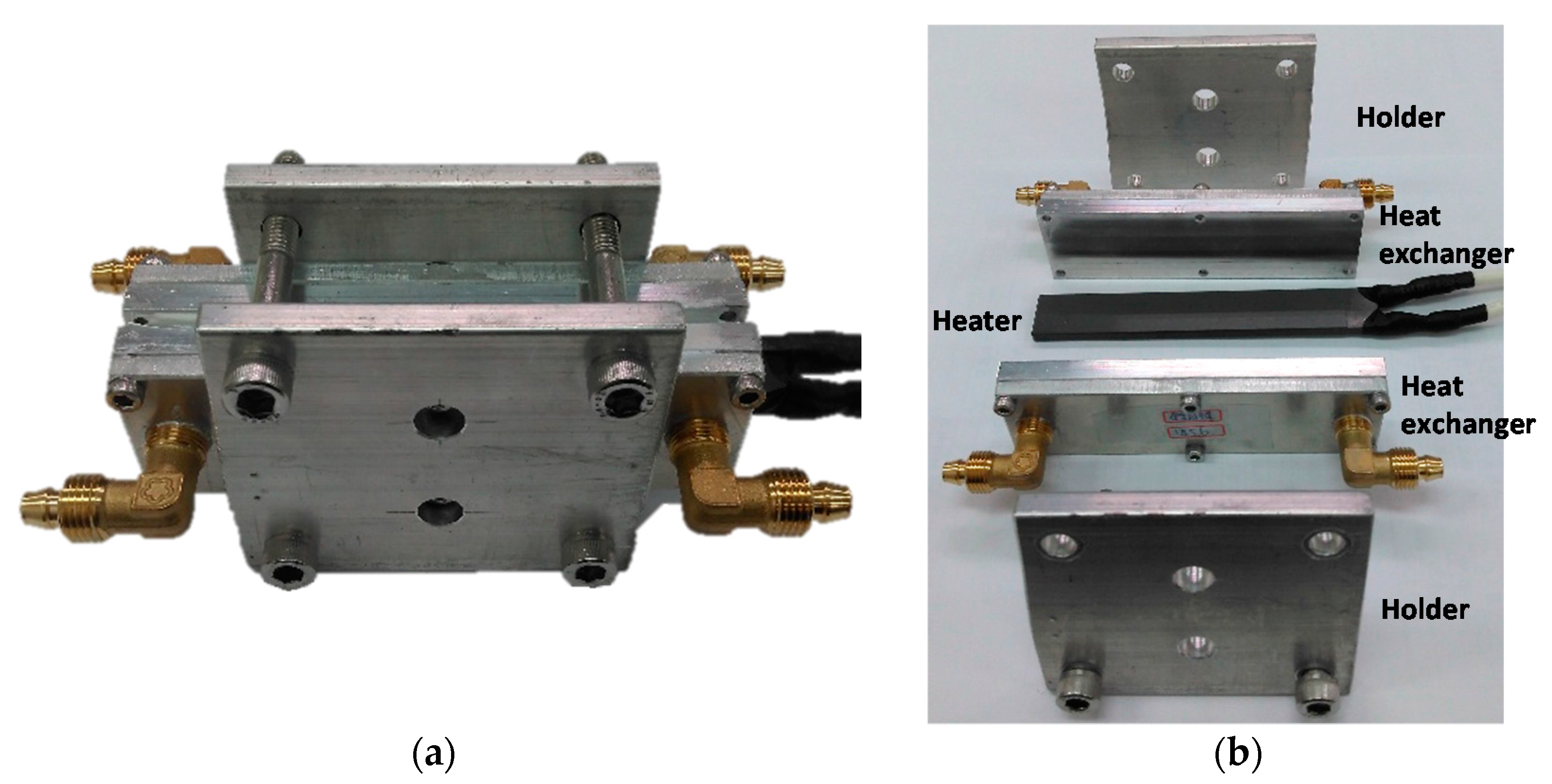
2.1. Experimental Setup for Air-Cooling Measurement

The air-cooling test platform, as shown in Figure 2, was comprised of an air supply system; a test section; a heating and temperature measurement system; and a data acquisition system. The air was supplied by a 5 HP air compressor. Compressed air was stored in an 800 L tank from which the air flow could be accurately regulated by a flow controller. The dryer and filter removed moisture and any fine particulate matter from the air. Then, the air with a given flow rate could enter into the test heat exchanger. The test section was made of Bakelite, which has very low thermal conductivity (1.4 W/m/K), see Figure 3. It was a rectangular box with 25 mm-thickness wall. The test heat exchanger was installed in this Bakelite box to reduce heat loss during testing. Three different cross-runner heat exchanger configurations were used: (1) the aluminum alloy heat exchanger with a staggered rectangular-fin array (Model A); (2) the aluminum alloy heat exchanger with a staggered round pin-fin array (Model B); and (3) the copper heat exchanger sintered by multiple copper sheets with rectangular punched holes forming cross runners (Model C). These three kinds of heat exchangers were made of various metal materials. Copper and aluminum alloy were common industrial metals and selected as the base materials. Copper has the thermal conductivity around 2.3 times that of aluminum alloy; it is about 3.1 times the mass of aluminum alloy and its unit price is also significantly above that of aluminum alloy. Based on heat transfer characteristics, copper is superior to aluminum alloy. However, the advantages of aluminum alloy in terms of cost and mass give this a niche value as a commodity for industrial applications. We designed the present Model A and Model B cross-runner heat exchangers to, separately, use aluminum-alloy rectangular fin arrays (Model A) and round-pin arrays (Model B) as the upper and lower parts of the heat exchanger. The fin or pin arrays on the upper and lower parts were staggered with respect to each other (see Figure 4a,b). When the inlet and outlet ports had been drilled and tapped, the two halves were fastened together by means of four side aluminum-alloy plates which were welded on to form an enclosed flow chamber. Model A was made with three different heights (H): Model A-1 for H = 3 mm; Model A-2 for H = 6 mm and Model A-3 for H = 9 mm. Model B was made with two various heights (H): Model B-1 for H = 6 mm and Model B-2 for H = 11 mm. Model C was another kind of cross-runner heat exchanger [21] (see Figure 4c), composed of a main body with water inlet and outlet fittings. The body was manufactured by sintering multiple 0.5 mm-thickness copper plates. There were four rectangular and two irregular holes punched at the plates. The two irregular holes were responsible for inlet and outlet, respectively, and the rectangular holes in adjacent plates were staggered with respect to one another. The assembly of cooper plates was held together by high-temperature bonding or sintering. Fluid entering the heat exchanger was forced to break into many small streams, in both series and parallel, which converge and break again many times as they followed the complex cross-runners to the outlet. This turbulent flow resulted in good heat transfer between the fluid and the heat dissipation surfaces. The final prototypes of various cross-runner heat exchanges (see Figure 5) were anodized to give them protection against corrosion. As listed in Table 1, they have different thermal properties, such as effective thermal conductivities, porosities and heat-transfer surface areas. These thermal properties would influence the total flow resistances and heat transfer characteristics in the present conjugate heat transfer issue. A stainless-steel thin-film heater was attached to the bottom of the Bakelite test section and there was Teflon tape on both sides of the film heater as insulation to prevent direct contact with the thermocouples which could result in errors or even short circuits. The film heater was powered by a DC power supply. Nine thermocouples (Model: TT-T-30, OMEGA Engineering Inc., Stamford, CT, USA) were located in the bottom of the test section. Each of the thermocouple junctions was welded to a copper sheet, which made close contact with the film heater by using high-conductivity thermal grease. The test heat exchanger was put in the test section and contacted closely on the other side of the film heater also by high-conductivity thermal grease. The distribution of thermocouples is shown in Figure 3. In addition, there were thermocouples at the inlet and outlet of the heat exchanger to measure the air flow temperature. The ambient temperature was also monitored. The outputs of thermocouples were connected to a data recorder (Model: MX-100, YOKOGAWA Meters & Instruments Corporation, Musashino, Tokyo, JAP) from where the data was transferred to a computer. A temperature change lower than 0.2 °C over 15 min was identified as a thermal steady-state condition. The static pressure drop (Δp) of fluid through the test specimen was measured by the pressure sensors connected to the inlet and outlet of the heat exchanger.

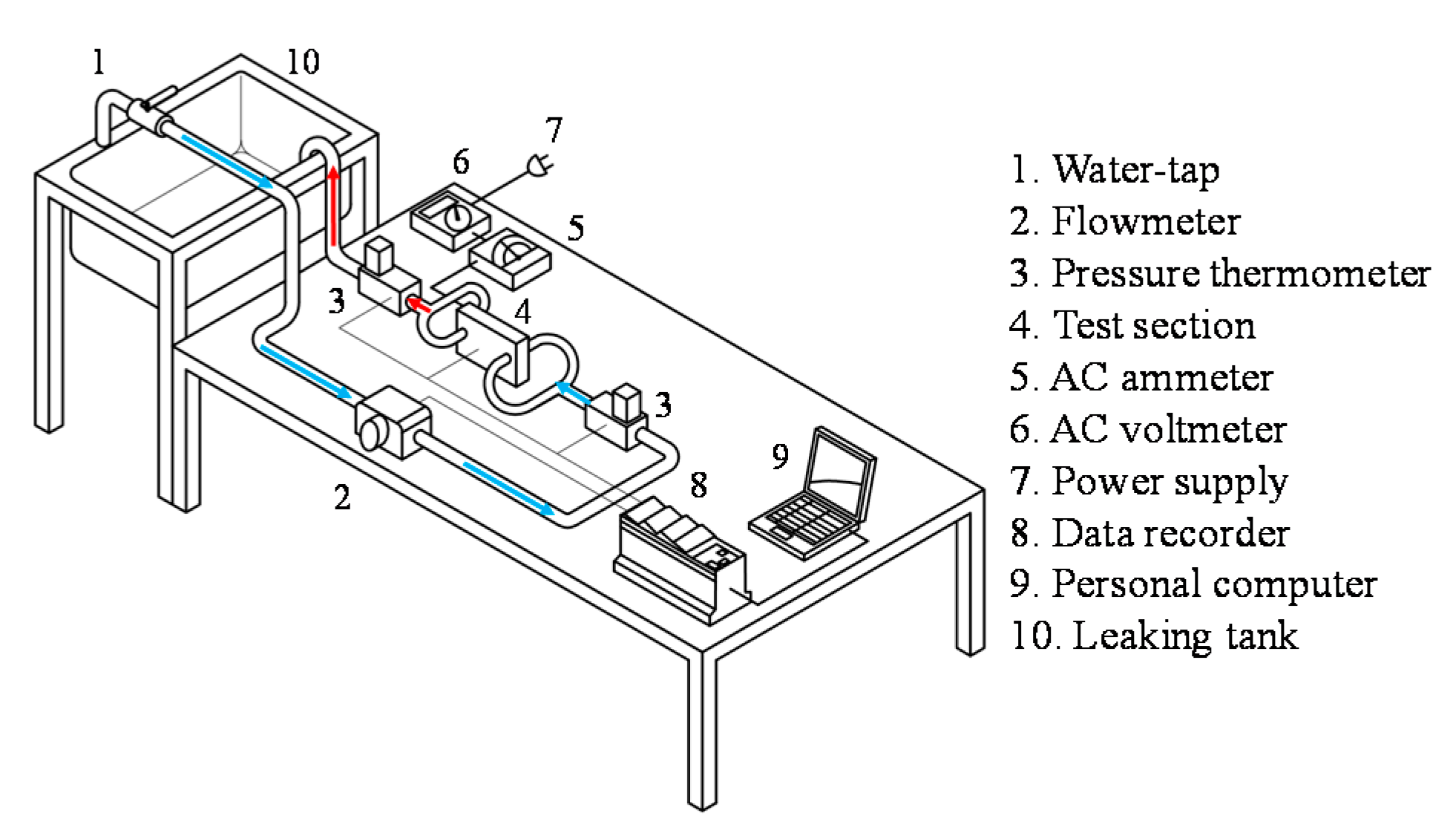
2.2. Experimental Setup for Water-Cooling Measurement

The water-cooling heat-transfer test platform, as shown in Figure 6, was used for the feasibility evaluation of the heat exchangers employed in the tank-less water heater (i.e., the instantaneous water heater). It consisted of an open-loop water supply system, a test section with a heater, and a data acquisition system. The open-loop water supply system provided continuous water flow from the water-tap. The water flow rate was regulated by the water-tap and measured by a flow meter. Water entered through the test section and finally flowed into the leaking tank. The test section, as shown in Figure 7, was comprised of a ceramic heater, two test heat exchangers and a set of holder. The ceramic heater was located between two test heat exchangers with the same configuration and all of them were fixed by the aluminum-alloy holder. Model A and Model C (see Figure 4) were selected as the typical cases. AC electric power with 220 V was provided to the heater to heat the given-rate water flow through two heat exchangers. The electric current and voltage were measured by the AC ammeter and AC voltmeter, respectively. The water temperatures at the inlet and outlet of the test section were monitored by the thermometers. Finally, the temperature history of heating water flow would be recorded by the YOKOGAWA MX-100 data recorder and computer.

2.3. Data Reduction and Uncertainty Analysis

For the air-cooling measurement, the flow rate and temperature were measured and the Reynolds number (Re), dimensionless pressure drop (ΔP*), dimensionless pumping power (W*), and average Nusselt number (Nu) were calculated using the following equations:
R e = ρ f Q f l o w μ · W
Δ P * = ( Δ p 0.5 ρ f ( Q f l o w / H / W ) 2 ) · ( R e L H ) 2
W * = ( Δ p 0.5 ρ f ( Q f l o w / H / W ) 2 ) · ( L H ) 2 · R e 3
N u = h L k f = ( Q i n Q l o s s ) L A ( T w T f ) k f
where Qflow is the volumetric flow rate; W, H and L are the internal width, height, and length of the heat exchanger under test; Tw is the average temperature of the heated wall; Tf is the bulk air mean temperature through the heat exchanger; Qin is the total input heat; Qloss is the lost heat; A (=W × L) is the area of the heated surface and Δp is the pressure drop through the heat exchanger. One needs to note that, according to the present definitions, the Reynolds number (Re) and average Nusselt number (Nu) really display the air flow rate though heat exchanger and the overall heat transfer capacity of heat exchanger, respectively. The fair comparison of overall heat transfer capacity cannot be obtained for the heat exchangers with various heights (H) if the characteristic length of Nu is the hydraulic diameter of heat exchanger instead of the fixed-value L.
In the forced convection heat transfer experiment, the total input heat (Qin) equals to the sum of the convective heat transferred to air flow (Qc) and the loss heat to the ambient (Qloss). In order to obtain the heat loss, we perform the heat loss estimation experiment. In that test, the inlet and outlet ends of the test section were closed and there would be no forced convection flow through the inlet and outlet. At this condition, the total input heat (Qin) supplied by the film heater almost equals to the lost heat (Qloss) as shown in Equation (5). Different total input heats (Qin) were set, and the wall temperature (Tw) and ambient temperature (T) corresponding to thermal equilibrium were recorded. The relationship between the lost heat (Qloss) and the temperature difference (TwT) could be determined. Then, the Nusselt number in the forced convection heat transfer experiment could be determined by substituting the result of Equation (5) into (4).
Q i n = V × I = Q l o s s = h l o s s A ( T w T )
The overall uncertainty is combined with the errors of measurement and calculation. The measurement error is resulted from the both deviations of the instrument and manual reading. The calculation error is obtained from alternative computations of measured data. The inaccuracy of the instrument was provided by the instrument manufacturer, and the inaccuracy of the temperature measurement was ±0.2 °C. This experiment used the estimation method proposed by Moffat [22] to evaluate parameter uncertainty. The uncertainties found for Re, ΔP*, W* and Nu were ±2.43%, ±3.61%, ±4.11%, and ±7.38%, respectively.

3. Results and Discussion

Figure 8 shows the relationship between the dimensionless pressure drop and the Reynolds number for different test heat exchangers. The lowest pressure drop was found in the model A. Model B showed a medium pressure drop. Model C showed the highest pressure drop. As shown in Table 1, Model C has the lowest porosity among the present test heat exchangers, resulting in the largest actual average aperture velocity in the cross runners of heat exchanger. Moreover, the heat transfer area (AHT) of Model C is quite large in a fixed volume (the second one in the test heat exchangers), increasing the skin friction and form drag. Therefore, at the same Reynolds number (i.e., the same volume flow rate), the maximum pressure drop is resulted from Model C. In addition, for the heat exchangers with the same configuration, for example Models A-1, A-2, and A-3, as well as Models B-1 and B-2, lower height would lead bigger pressure drop due to the interaction result of increasing actual average aperture velocity and decreasing heat-transfer area in the cross runners. In order to identify the effects of actual average aperture velocity and heat-transfer area on the pressure drop, the relation between the dimensionless pressure drop (ΔP*) and the Reynolds number based on the average aperture velocity (Re*) is plotted in Figure 9. It is found that, for the heat exchangers with the same configuration and at the same Re*, increasing the height of heat-exchanger promoted ΔP* because of the increase of heat-transfer area. The ΔP* increased with the power of Re*. The power of Re* ranged from 1.411 to 1.862 and the average value was 1.756. According to the relationship between ΔP* and Re* as well as the heat-transfer area in Table 1, an empirical correlation of ΔP* in terms of Re*, ε and AHT/W/L with deviation less than 10% is expressed as Equation (6) and Equation (7). Figure 10 shows the experimental data and predicting results.
Δ P * = C 1 ( A H T W L ) m ( Re * ) n 1
where  Re * = Re ( W H ) ( 1 ε ) ,   m = 4.06 ε 1.862 ,   n 1 = 1.756 ,   C 1 = 454   f o r   M o d e l   A = 1590   f o r   M o d e l   B = 5939   f o r   M o d e l   C
Figure 11 shows the relationship between the Nusselt number (Nu) and Reynolds number (Re) when the heat exchangers were cooled by air. The result demonstrates that for the same Reynolds number, the Nusselt number of Model C was far larger than those of Models A and B. It depicts that Model C has a much greater heat exchange capacity. Additionally, the Nusselt number of Model B was medium and that of Model A was the lowest. It should be explained as follows: for the heat exchangers herein, the heat transfer mechanism is the conjugate heat transfer combining, firstly, thermal conduction from the heated wall to the fin surface, and then series connection with thermal convection from the fin surface to the fluid. Therefore, the key factors influencing the overall heat transfer are the effective thermal conductivity (ke), the total heat-transfer area (AHT), the porosity (ε) and the porous-like structure. The bigger effective thermal conductivity (ke) is desired for the better thermal conduction, while larger heat-transfer area (AHT), lower porosity (ε) and the complex porous-like structure are necessary for obtaining more effective forced convection heat transfer. See Table 1, the Model C is the most consistent with the above-mentioned conditions and following with Model B and Model A, sequentially. Furthermore, a semi-empirical correlation of the Nusselt number is derived according to the conjugate heat transfer mechanism.
Q c = ( H 2 A k e + 1 A H T h s f ) 1 ( T w T f )
Assuming  N u s f = h s f D h k f = C 2 ( Re D h ) n 2
Re D h = Re ( D h H ) ( 1 ε )
D h = 4 V v o i d A H T = 4 L W H ε A H T
Substituting Equations (4) and (9)–(11) into (8), one can obtain the following expression:
N u = ( H 2 L k f k e + 1 C 2 ( Re D h ) n 2 D h L A A H T ) 1
Rearranging Equation (12) and the solid-to-fluid Nusselt number (Nusf) in terms of the Reynolds number based on average aperture velocity and hydraulic diameter (ReDh) will be obtained as Equation (13):
N u s f = ( N u 1 H 2 L k f k e ) 1 A A H T D h L = C 2 ( Re D h ) n 2
where Qc is the convective heat transferred to air flow; H and L are the internal height and length of the heat exchanger; Tw is the average temperature of the heated wall; Tf is the bulk air mean temperature through the heat exchanger; A (=W × L) is the area of the heated surface; AHT and ke are the total heat-transfer surface area and effective thermal conductivity of the heat exchanger; kf is the thermal conductivity of fluid; hsf is the heat transfer coefficient between the fluid and the solid fins in the heat exchanger; Vvoid is the void volume in the heat exchanger and Dh is the porous hydraulic diameter of cross-runners in the heat exchanger.
According to all the air-cooling experimental data in the present study, the relevant constants C2 and n2 are listed in Table 2. The experimental results and the prediction by the empirical correlation Equation (13) are shown in Figure 12. Both of the solid-to-fluid Nusselt number (Nusf) and the average-aperture-velocity Reynolds number (ReDh) are based on the porous hydraulic diameter (Dh). Therefore, the present correlation can be more widely used. The Nusselt number predicted by the most popular formula of Dittus and Boelter [23] is also plotted in Figure 12, showing a reasonable comparison result. The average deviation between the experimental data and the present prediction is less than 1%. Figure 13 shows the relationship between Nusselt number and dimensionless pumping power. Under the same pumping power, the heat transfer capacity of Model C is 2.27 and 1.67 times that of Model A and Model B, respectively. This makes it clear that the heat transfer enhancement of Model C is adequate compensation for the increase in flow resistance.
Figure 14 and Figure 15 show the results of the water-cooling measurement. Models A-1, A-2, A-3, and C were selected as the typical cases. Figure 14 displays the relationship between the temperature rise (i.e., ΔT, water temperature difference between inlet and outlet of the heat exchanger) and water flow rate at the thermal-equilibrium condition. The theoretical value predicted by the energy-balance method is also plotted in Figure 14. It is found that the ΔT of Model C, with an excellent heat transfer capacity, almost agreed with theoretical value. It means the very high heat-transfer performance of Model C almost resulted in no heat loss. In other words, almost all the input electrical power was transmitted by the Model C to the water flow. By comparing with Model C, Model A has 7.7%–15% of input heat to be lost at the present range of water flow rate from 2 to 5 L/min. In general, under the no-insulation condition, the heat exchanger with better heat transfer capacity would lead less heat loss. It would be an energy-saving device. Figure 15 shows that the steady-state temperature can be reached in about 75 s, this conserves energy and demonstrates that the Model C can be useful as a heat exchanger in the application of instantaneous water heating. The model C heat exchanger design is a practical one that has great commercial potential.

4. Conclusions

This study proposed three designs of cross-runner heat exchanger: (1) the aluminum alloy heat exchanger with a staggered rectangular-fin array (Model A); (2) the aluminum alloy heat exchanger with a staggered round pin fin array (Model B); and (3) the copper heat exchanger sintered by multiple copper sheets with rectangular punched holes forming cross-runners (Model C). The main conclusions are listed as follows.
(1)
Increasing the heat-transfer area (AHT) and decreasing the porosity (ε) of the heat exchanger will obviously increase the flow resistance of the cross-runner heat exchanger.
(2)
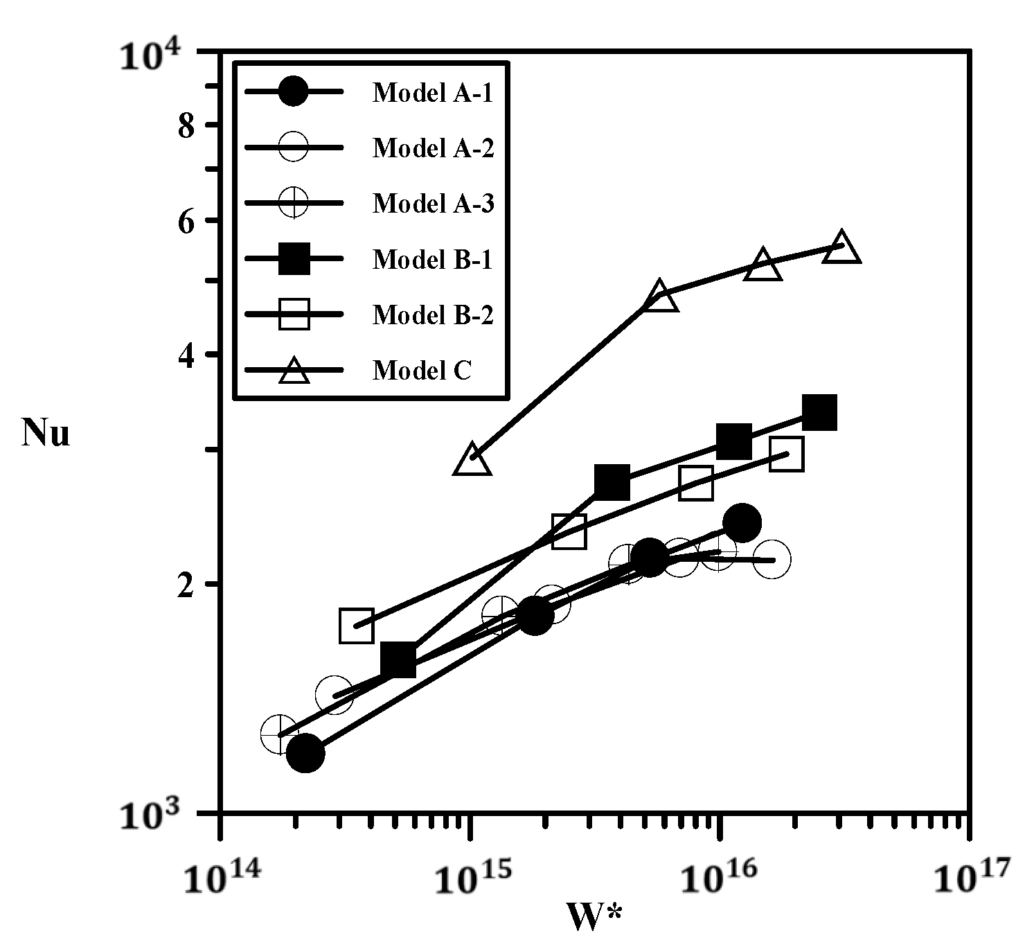
The larger effective thermal conductivity (ke), larger heat-transfer area (AHT), and lower porosity (ε) are desired for the better conjugate heat transfer performance.
(3)
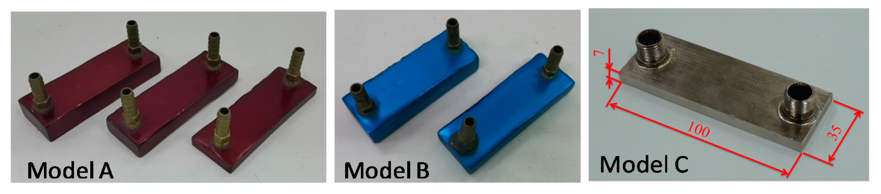
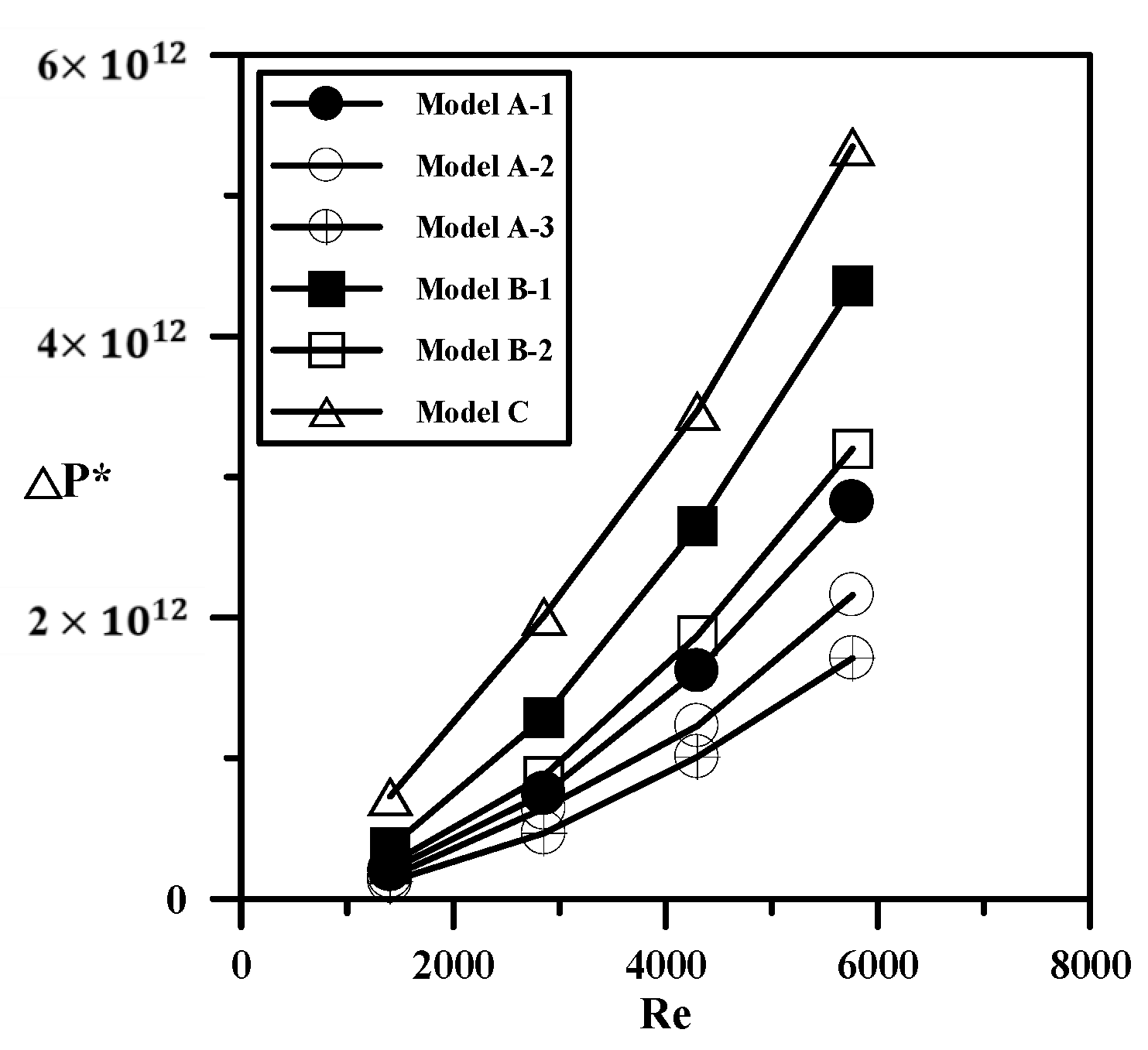
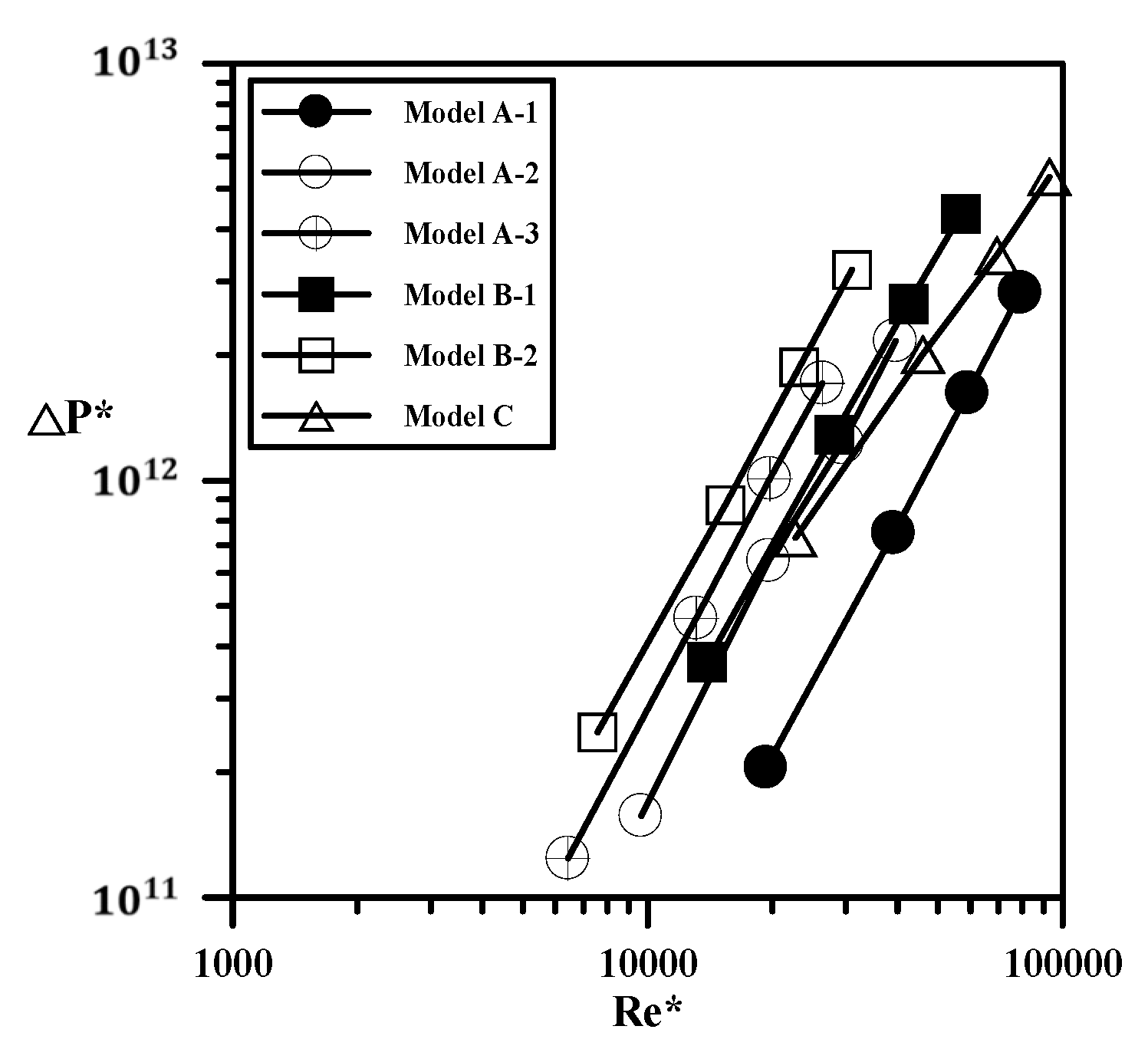
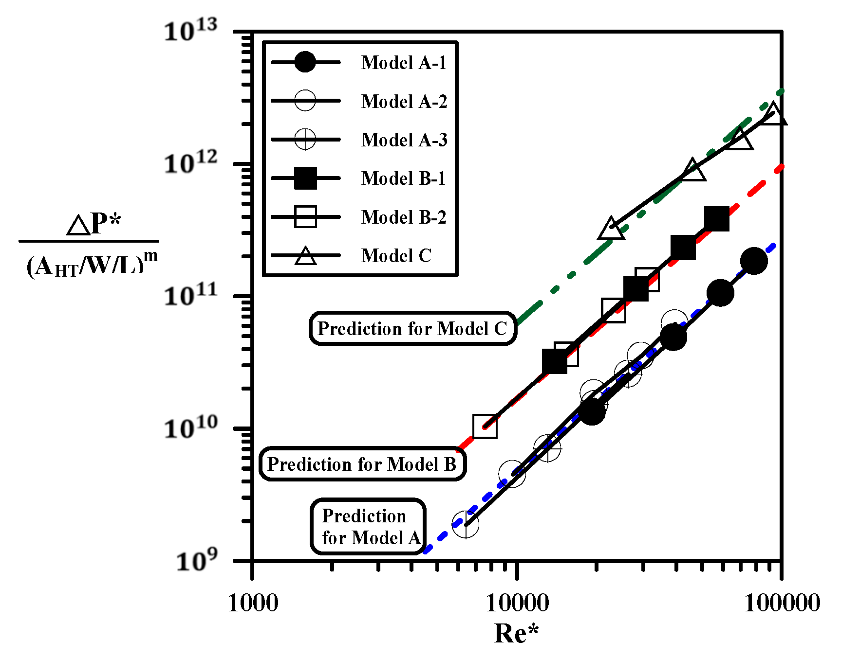
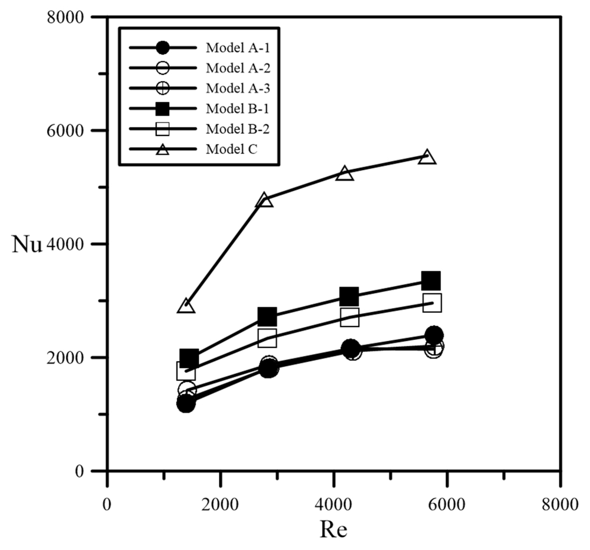
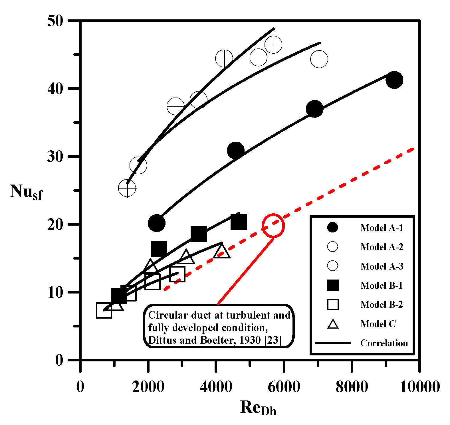
The experimental measurements using air-cooled heat transfer indicated that under the same pumping power, the heat transfer capacity of Model C was 2.27 and 1.67 times that of Models A and B, respectively. The semi-empirical correlations of the dimensionless pressure drop and Nusselt number in terms of the Reynolds number for different heat exchangers with various ke, AHT, and ε were proposed.
(4)
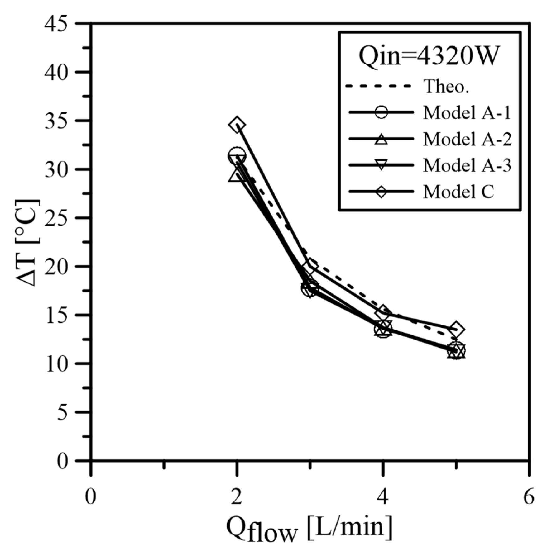
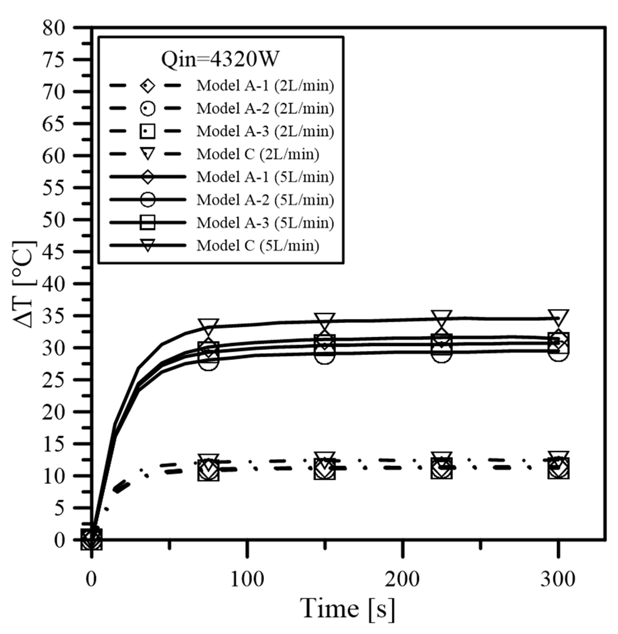
The feasibility of Model C as the heat exchanger for use in instantaneous water heating applications was confirmed by the water-cooling tests. The results showed the design has great commercial potential.

Acknowledgments

The author would like to thank the Ministry of Science and Technology of the Republic of China for financial support of this research under Contracts: MOST 103-2632-E-270-001-MY3, MOST 103-2221-E-270-008, MOST 103-2622-E-270-005-CC3, and MOST 104-2815-C-270-006-E.

Author Contributions

Tzer-Ming Jeng led this work as well as guided the experimental tests and data analysis; Sheng-Chung Tzeng participated discussions and was responsible for correspondence, Ching-Wen Tseng performed experimental tests, Chia-Hung Chang built the experimental setup, Yi-Cheng Liu performed experimental tests, Hsiao-Yun Peng drew figures and Huang-Han Chen participated discussions.

Conflicts of Interest

The authors declare no conflict of interest.

References

  1. Vanfossen, G.J. Heat-transfer coefficients for staggered arrays of short pin fins. ASME J. Eng. Gas Turbines Power 1982, 104, 268–274. [Google Scholar] [CrossRef]
  2. Brigham, B.A.; Vanfossen, G.J. Length to diameter ratio and row number effects in short pin fin heat transfer. ASME J. Eng. Gas Turbines Power 1984, 106, 241–244. [Google Scholar] [CrossRef]
  3. Metzger, D.E.; Fan, C.S.; Haley, S.W. Effects of pin shape and array orientation on heat transfer and pressure loss in pin fin arrays. ASME J. Eng. Gas Turbines Power 1984, 106, 252–257. [Google Scholar] [CrossRef]
  4. Zukauskas, A.; Ulinskas, R. Efficiency parameters for heat transfer in tube banks. Heat Transf. Eng. 1985, 6, 19–25. [Google Scholar] [CrossRef]
  5. Armstrong, J.; Winstanley, D. A review of staggered array pin fin heat transfer for turbine cooling applications. ASME J. Turbomach. 1988, 110, 94–103. [Google Scholar] [CrossRef]
  6. Jubran, B.A.; Hamdan, M.A.; Abdualh, R.M. Enhanced heat transfer, missing pin, and optimization for cylindrical pin fin arrays. ASME J. Heat Transf. 1993, 115, 576–583. [Google Scholar] [CrossRef]
  7. Tahat, M.A.; Babus’Haq, R.F.; Probert, S.D. Forced steady-state convections from pin-fin arrays. Appl. Energy 1994, 48, 335–351. [Google Scholar] [CrossRef]
  8. Tahat, M.; Kodah, Z.H.; Jarrah, B.A.; Probert, S.D. Heat transfer from pin-fin arrays experiencing forced convection. Appl. Energy 2000, 67, 419–442. [Google Scholar] [CrossRef]
  9. Babus’Haq, R.F.; Akintunde, K.; Probert, S.D. Thermal performance of a pin-fin assembly. Int. J. Heat Fluid Flow 1995, 16, 50–55. [Google Scholar] [CrossRef]
  10. Sara, O.N.; Yapici, S.; Yilmaz, M.; Pekdemir, T. Second law analysis of rectangular channels with square pin-fins. Int. Commun. Heat Mass Transf. 2001, 28, 617–630. [Google Scholar] [CrossRef]
  11. Sara, O.N. Performance analysis of rectangular ducts with staggered square pin fins. Energy Convers. Manag. 2003, 44, 1787–1803. [Google Scholar] [CrossRef]
  12. Wang, Q.; Zeng, M.; Ma, T.; Du, X.; Yang, J. Recent development and application of several high-efficiency surface heat exchangers for energy conversion and utilization. Appl. Energy 2014, 15, 748–777. [Google Scholar] [CrossRef]
  13. Chen, L.; Feng, H.; Xie, Z.; Sun, F. Thermal efficiency maximization for H- and X-shaped heat exchangers based on constructal theory. Appl. Therm. Eng. 2015, 91, 456–462. [Google Scholar] [CrossRef]
  14. Li, W.; Yang, L.; Ren, J.; Jiang, H. Effect of thermal boundary conditions and thermal conductivity on conjugate heat transfer performance in pin fin arrays. Int. J. Heat Mass Transf. 2016, 95, 579–592. [Google Scholar] [CrossRef]
  15. Jadhav, R.S.; Balaji, C. Fluid flow and heat transfer characteristics of a vertical channel with detached pin-fin arrays arranged in staggered manner on two opposite endwalls. Int. J. Therm. Sci. 2016, 105, 57–74. [Google Scholar] [CrossRef]
  16. Schampheleire, S.D.; Jaeger, P.D.; Kerpel, K.D.; Ameel, B.; Huisseune, H.; Paepe, M.D. How to study thermal applications of open-cell metal foam: experiments and computational fluid dynamics. Materials 2016, 9, 94–120. [Google Scholar] [CrossRef] [Green Version]
  17. Chen, K.-C.; Wang, C.-C. Performance improvement of high power liquid-cooled heat sink via non-uniform metal foam arrangement. Appl. Therm. Eng. 2015, 87, 41–46. [Google Scholar] [CrossRef]
  18. Abadi, G.B.; Moon, C.; Kim, K.C. Experimental study on single-phase heat transfer and pressure drop of refrigerants in a plate heat exchanger with metal-foam-filled channels. Appl. Therm. Eng. 2016, 102, 423–431. [Google Scholar] [CrossRef]
  19. Feng, S.S.; Kuang, J.J.; Wen, T.; Lu, T.J.; Ichimiy, K. An experimental and numerical study of finned metal foam heat sinks under impinging air jet cooling. Int. J. Heat Mass Transf. 2014, 77, 1063–1074. [Google Scholar] [CrossRef]
  20. Shih, W.-H.; Liu, C.-C.; Hsieh, W.-H. Heat-transfer characteristics of aluminum-foam heat sinks with a solid aluminum core. Int. J. Heat Mass Transf. 2016, 97, 742–750. [Google Scholar] [CrossRef]
  21. Chen, H.-H. A Heat Exchanger of Sheet Configuration. Patent of ROC M428652, 1 May 2012. [Google Scholar]
  22. Moffat, R.J. Contributions to the theory of single-sample uncertainty analysis. ASME J. Fluids Eng. 1982, 104, 250–258. [Google Scholar] [CrossRef]
  23. Dittus, P.W.; Boelter, L.M.K. Heat Transfer in Automobile Radiators of the Tubular Type; University of California publications in engineering; University of California Press: Berkeley, CA, USA, 1930; Volume 2, pp. 443–461, reprinted in Int. Comm. Heat Mass Transf. 1985, 12, 3–22. [Google Scholar] [CrossRef]
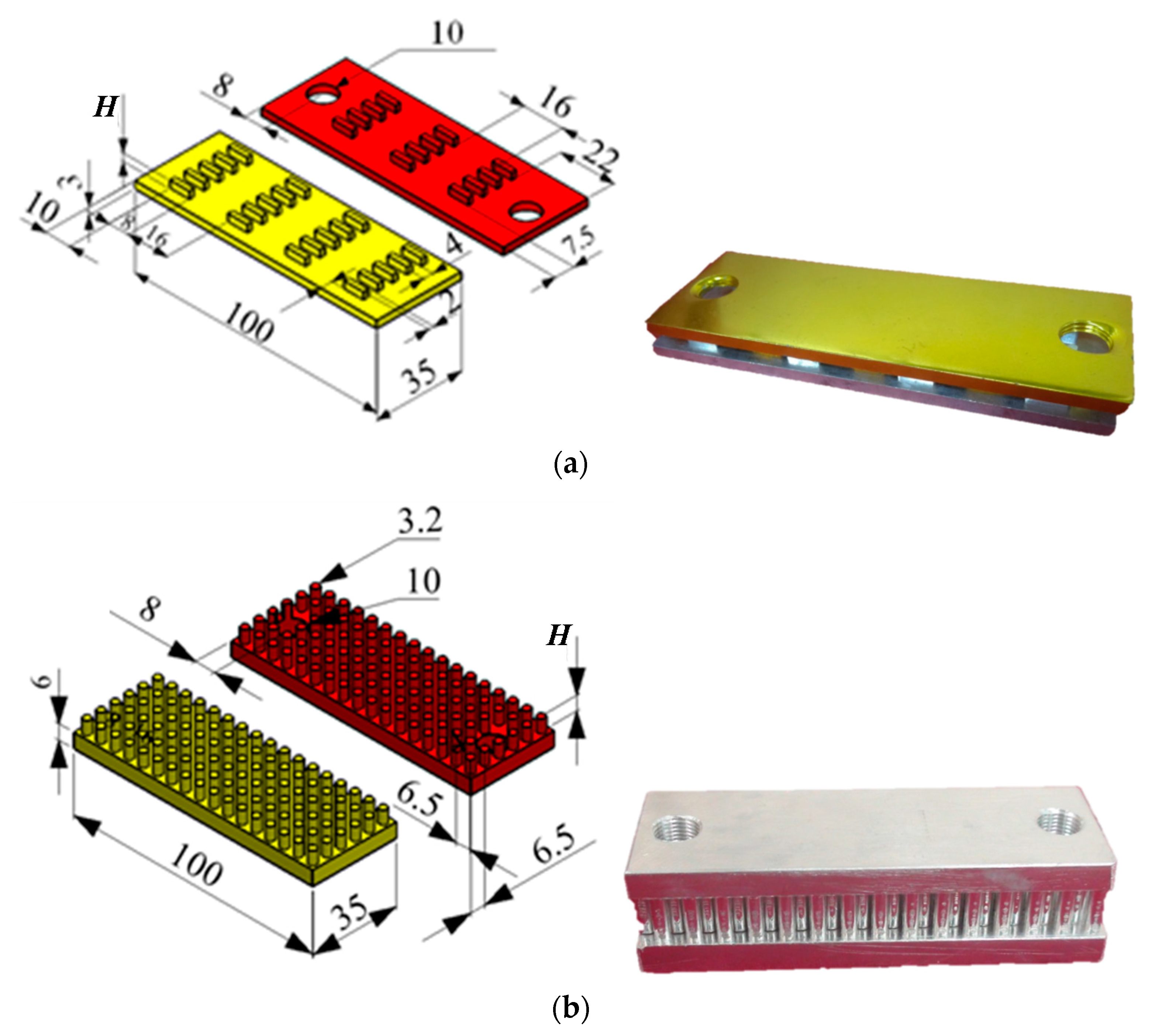
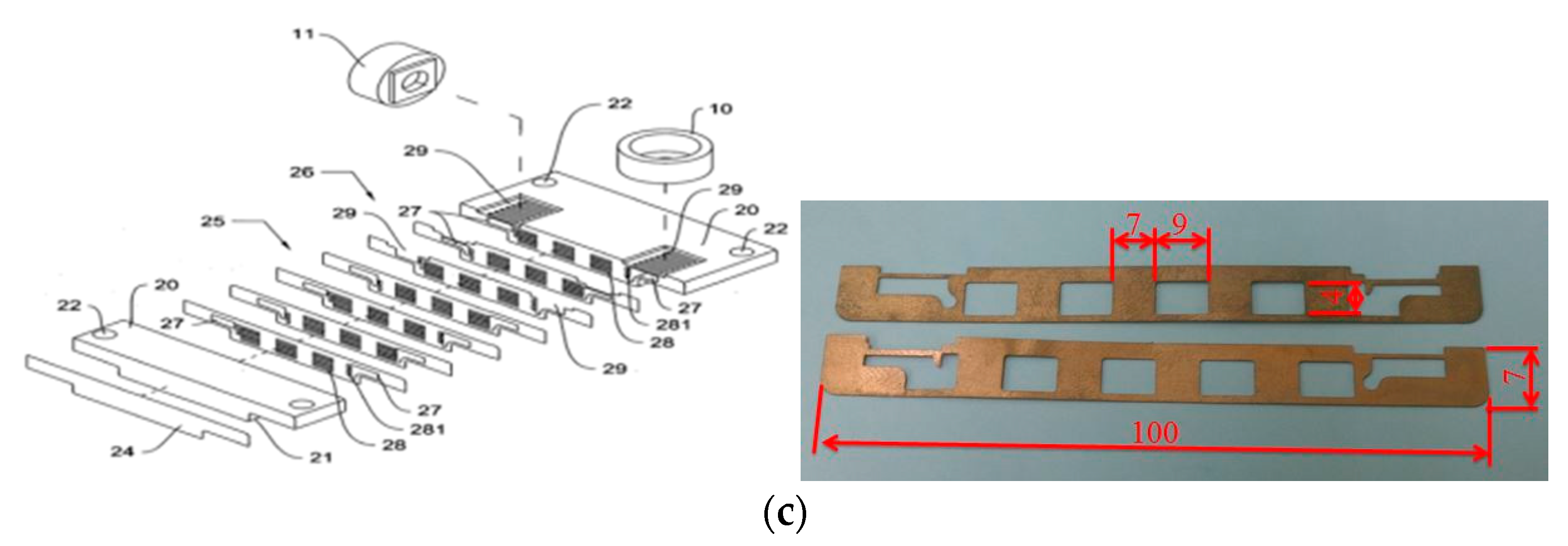
Figure 1. Top-view diagram of the flow pattern in the internal runners of the present heat exchanger. (the arrows show the flow directions of fluid; the white and red boxes are separately the fins grown from the bottom and upper walls; the left and right red dashed circular are the inlet and outlet respectively).
Inventions 01 00010 g001
Figure 2. Experimental setup for air-cooling measurement.
Inventions 01 00010 g002
Figure 3. The test section for air-cooling measurement (units: mm).
Inventions 01 00010 g003
Figure 4. Configurations and dimensions of various heat exchangers (unit: mm). (a) Model A: the left drawing shows the bottom (yellow) and upper (red) parts; the right is the physical combination; (b) Model B: the left drawing shows the bottom (yellow) and upper (red) parts; the right is the physical combination; and (c) Model C: the left drawing is the exploded view in where the numbers mean different decomposition parts [21]; the right displays the copper plates used to manufacture Model C.
Inventions 01 00010 g004aInventions 01 00010 g004b
Figure 5. The prototypes of various heat exchangers (unit: mm): the left drawing shows the Model A heat exchangers of three heights; the center shows Model B heat exchangers of two heights; the right is Model C heat exchanger.
Inventions 01 00010 g005
Figure 6. Experimental setup for water-cooling measurement.
Inventions 01 00010 g006
Figure 7. The test section for water-cooling measurement. (a) The combination assembly of the test section; (b) the decomposition parts of the test section.
Inventions 01 00010 g007
Figure 8. Relationship between ΔP* and Re.
Inventions 01 00010 g008
Figure 9. Relationship between ΔP* and Re*.
Inventions 01 00010 g009
Figure 10. Correlation for ΔP* in terms of Re* and AHT/W/L.
Inventions 01 00010 g010
Figure 11. Relationship between Nu and Re.
Inventions 01 00010 g011
Figure 12. Correlation for Nusf in terms of ReDh.
Inventions 01 00010 g012
Figure 13. Relationship between Nu and W*.
Inventions 01 00010 g013
Figure 14. Relationship between temperature rise and water flow rate.
Inventions 01 00010 g014
Figure 15. Water temperature history.
Inventions 01 00010 g015
Table 1. List of the relevant thermal properties for the test heat exchangers herein.
Model TypeMaterial ε ks* (≅ke) [W/m/K]AHT [m2] × 106
Model A-1Al-alloy0.8524.68706
Model A-2Al-alloy0.8524.611436
Model A-3Al-alloy0.8524.614166
Model B-1Al-alloy0.5967.217272
Model B-2Al-alloy0.5967.228235
Model CCopper0.3125719320
Table 2. Corresponding factors in Equations (9) and (13).
Model TypeC2n2
Model A-10.3920.513
Model A-22.5180.330
Model A-31.0410.445
Model B-10.2080.549
Model B-20.5650.392
Model C0.3460.469

