
Apparatus and Experiments Towards Fully Automated Medical Isotope Production Using an Ion Beam Accelerator

 , , and
Abstract
1. Introduction
- Target holder fabrication
- Target physical form
- Efficient chemical separation
- Photolabelling system integration
- Application of 3D printing technologies
2. Materials and Methods
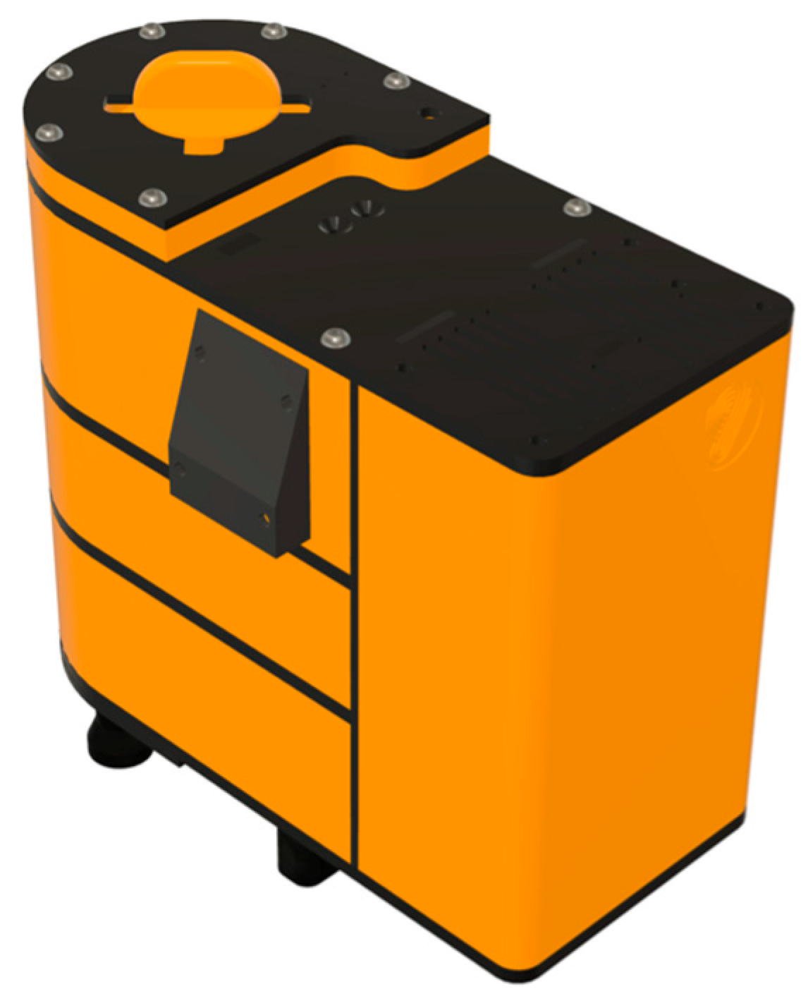
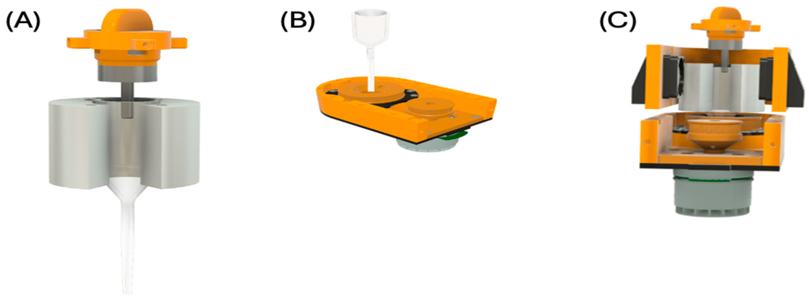
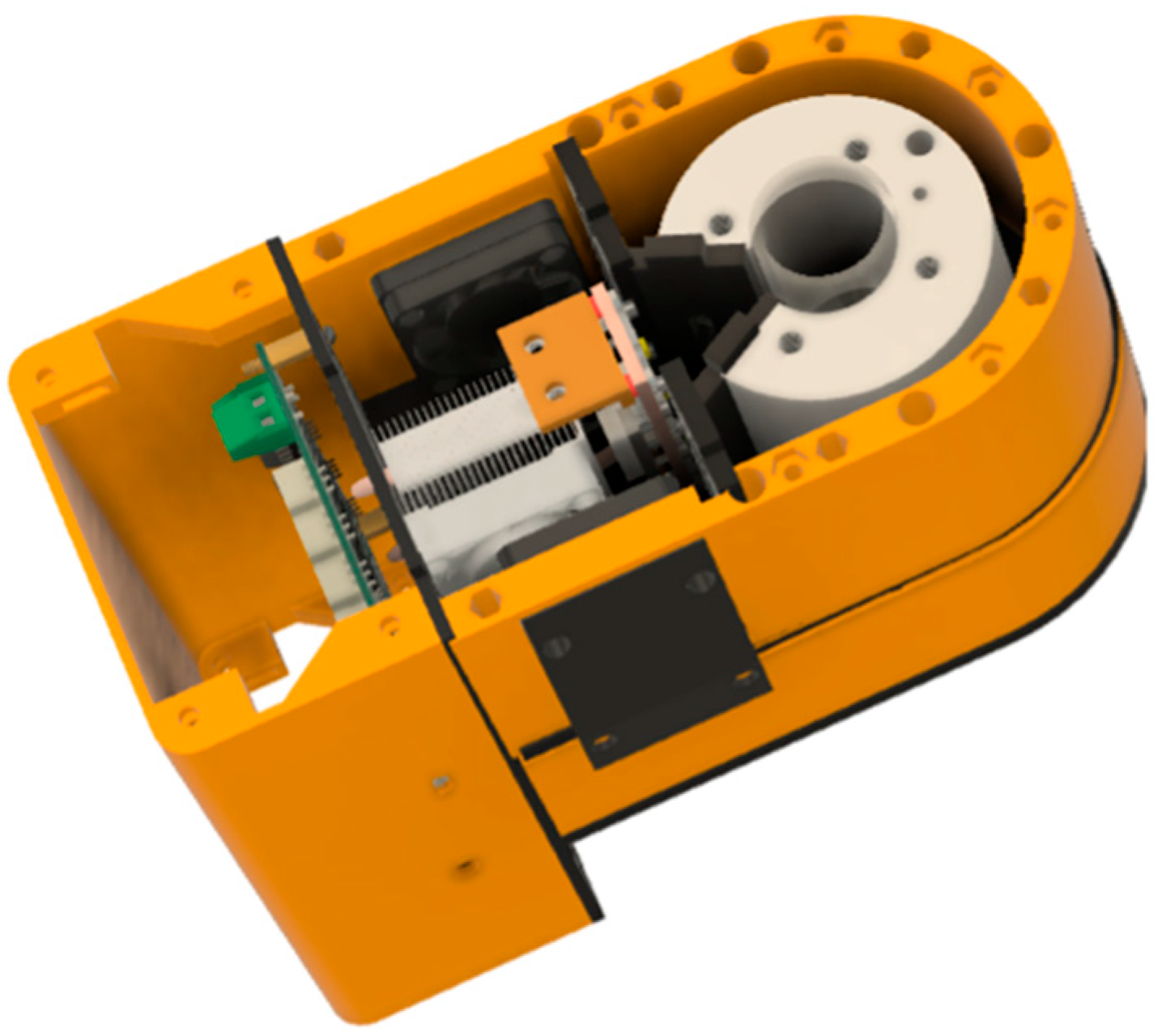
2.1. Target Holder and Translator
2.2. Chemical Separation Unit
2.3. Photolabelling, Vortex Mixing, and Controlled Heating Unit
2.4. Vortexing and Controlled Heating
2.5. Photolabelling
3. Results
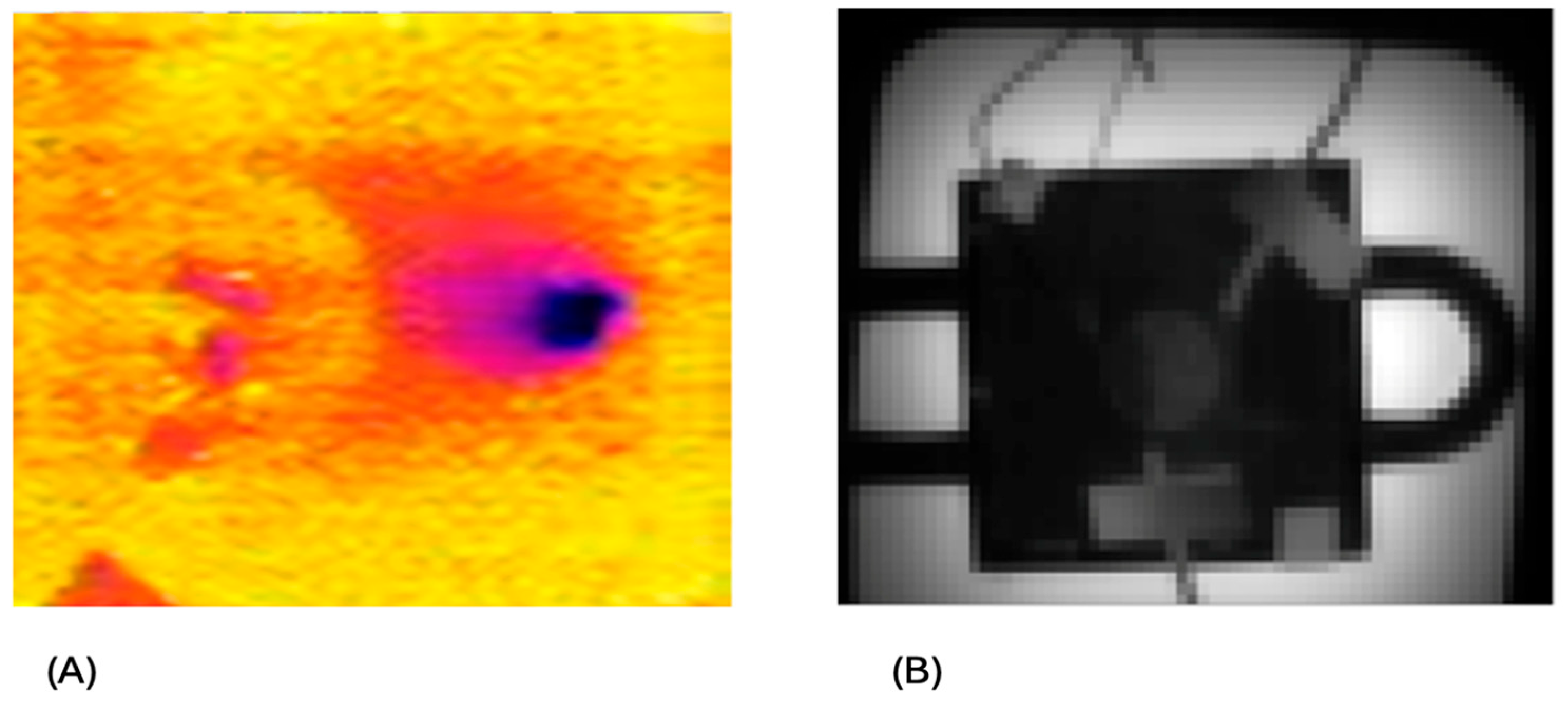
3.1. Irradiation
3.2. Zr/Y Separation
3.3. Photolabelling, Vortex Mixing, and Controlled Heating
4. Discussion
4.1. Target Holder
4.2. Chemical Separation Unit
4.3. Photolabelling, Vortex Mixing, and Controlled Heating
5. Conclusions
Supplementary Materials
Author Contributions
Funding
Data Availability Statement
Acknowledgments
Conflicts of Interest
References
- Guillou, A.; Earley, D.F.; Patra, M.; Holland, J.P. Light-induced synthesis of protein conjugates and its application in photoradiosynthesis of 89Zr-radiolabeled monoclonal antibodies. Nat. Protoc. 2020, 15, 3579–3594. [Google Scholar] [CrossRef] [PubMed]
- Holland, J.P.; Sheh, Y.; Lewis, J.S. Standardized methods for the production of high specific-activity zirconium-89. Nucl. Med. Biol. 2009, 36, 729–739. [Google Scholar] [CrossRef] [PubMed]
- De Feo, M.S.; Pontico, M.; Frantellizzi, V.; Corica, F.; De Cristofaro, F.; De Vincentis, G. 89Zr-PET imaging in humans: A systematic review. Clin. Transl. Imaging 2022, 10, 23–36. [Google Scholar] [CrossRef]
- Gaja, V.; Cawthray, J.; Geyer, C.R.; Fonge, H. Production and semi-automated processing of 89Zr using a commercially available TRASIS miniAiO module. Molecules 2020, 25, 2626. [Google Scholar] [CrossRef] [PubMed]
- ALECO. ALCEO Solid Target Processing System. Available online: www.comecer.com/alceo-solid-target-processing-system (accessed on 2 November 2022).
- Nitra, Nirta® Target Technology. Available online: https://www.iba-radiopharmasolutions.com/cyclotrons-equipment/#solid (accessed on 2 November 2022).
- Gelbart, W.Z.; Johnson, R.R. Solid Target System with In-Situ Target Dissolution. Instruments 2019, 3, 14. [Google Scholar] [CrossRef]
- Imura, R.; Ozeki, A.N.; Shida, N.; Kobayashi, M.; Ida, H.; Wada, Y.; Akimitsu, N.; Kumakura, Y. Radiolabeling of PSMA-617 with 89Zr: A novel use of DMSO to improve radiochemical yield and preliminary small-animal PET results. Nucl. Med. Biol. 2022, 106–107, 21–28. [Google Scholar] [CrossRef] [PubMed]
- Blanco, I. The Use of Composite Materials in 3D Printing. J. Compos. Sci. 2020, 4, 42. [Google Scholar] [CrossRef]
- Dejesus, O.T.; Nickles, R.J. Production and purification of 89Zr, a potential PET antibody label. Int. J. Rad. Appl. Instrum. A 1990, 41, 789–790. [Google Scholar] [CrossRef]
- Qaim, S.M. Development of novel positron emitters for medical applications: Nuclear and radiochemical aspects. Radiochim. Acta 2011, 99, 611–625. [Google Scholar] [CrossRef]
- Qaim, S.M.; Scholten, B.; Spahn, I.; Neumaier, B. Positron-emitting radionuclides for applications, with special emphasis on their production methodologies for medical use. Radiochim. Acta 2019, 107, 1011–1026. [Google Scholar] [CrossRef]
- Pandey, M.K.; Engelbrecht, H.P.; Byrne, J.P.; Packard, A.B.; DeGrado, T.R. Production of 89Zr via the 89Y(p, n)89Zr reaction in aqueous solution: Effect of solution composition on in-target chemistry. Nucl. Med. Biol. 2014, 41, 309–316. [Google Scholar] [CrossRef] [PubMed]
- Queern, S.L.; Aweda, T.A.; Massicano, A.V.; Clanton, N.A.; El Sayed, R.; Sader , J.A.; Zyuzin, A.; Lapi, S.E. Production of Zr-89 using sputtered yttrium coin targets 89Zr using sputtered yttrium coin targets. Nucl. Med. Biol. 2017, 50, 11–16. [Google Scholar] [CrossRef] [PubMed]
- Larenkov, A.; Bubenschikov, V.; Makichyan, A.; Zhukova, M.; Krasnoperova, A.; Kodina, G. Preparation of zirconium-89 solutions for radiopharmaceutical purposes: Interrelation between formulation, radiochemical purity, stability and biodistribution. Molecules 2019, 24, 1534. [Google Scholar] [CrossRef] [PubMed]
- Ellison, P.A.; Valdovinos, H.F.; Graves, S.A.; Barnhart, T.E.; Nickles, R.J. Spot-welding solid targets for high current cyclotron irradiation. Appl. Radiat. Isot. 2016, 118, 350–353. [Google Scholar] [CrossRef] [PubMed]
- Meijs, W.E.; Herscheid, J.D.M.; Haisma, H.J.; Wijbrandts, R.; van Langevelde, F.; Van Leuffen, P.J.; Mooy, R.; Pinedo, H.M. Production of highly pure no-carrier added 89Zr for the labelling of antibodies with a positron emitter. Appl. Radiat. Isot. 1994, 45, 1143–1147. [Google Scholar] [CrossRef]
- Kandil, S.A.; Scholten, B.; Saleh, Z.A.; Youssef, A.M.; Qaim, S.M.; Coenen, H.H. A comparative study on the separation of radiozirconium via ion-exchange and solvent extraction techniques, with particular reference to the production of 88Zr and 89Zr in proton induced reactions on yttrium. J. Radioanal. Nucl. Chem. 2007, 274, 45–52. [Google Scholar] [CrossRef]
- Wooten, A.L.; Madrid, E.; Schweitzer, G.D.; Lawrence, L.A.; Mebrahtu, E.; Lewis, B.C.; Lapi, S.E. Routine Production of 89Zr Using an Automated Module. Appl. Sci. 2013, 3, 593–613. [Google Scholar] [CrossRef]
- Link, J.M.; Krohn, K.A.; Eary, J.F. 89Zr for antibody labeling and positron emission tomography. J. Label. Compd. Radiopharm. 1986, 23, 1297–1298. [Google Scholar]
- Bouakkaz, A.O.; Albedah, A.; Bouiadjra, B.B.; Khan, S.M.A.; Benyahia, F.; Elmeguenni, M. Effect of temperature on the mechanical properties of polypropylene–talc composites. J. Thermoplast. Compos. Mater. 2018, 31, 896–912. [Google Scholar] [CrossRef]
- Rana, A.S.; Zubair, M.; Danner, A.; Mehmood, M.Q. Revisiting tantalum based nanostructures for efficient harvesting of solar radiation in STPV systems. Nano Energy 2021, 80, 105520. [Google Scholar] [CrossRef]
- Verel, I.; Visser, G.W.M.; Boellaard, R.; Walsum, M.S.-V.; Snow, G.B.; van Dongen, G.A.M.S. Basic Science Investigations 89 Zr Immuno-PET: Comprehensive Procedures for the Production of 89 Zr-Labeled Monoclonal Antibodies. J. Nucl. Med. 2003, 44, 1271–1281. [Google Scholar] [PubMed]
- Patra, M.; Eichenberger, L.S.; Fischer, G.; Holland, J.P. Photochemische Konjugation und Eintopfradiomarkierung von Antikörpern für Immun-PET. Angew. Chem. 2019, 131, 1946–1951. [Google Scholar] [CrossRef]
- Patra, M.; Klingler, S.; Eichenberger, L.S.; Holland, J.P. Simultaneous Photoradiochemical Labeling of Antibodies for Immuno-Positron Emission Tomography. iScience 2019, 13, 416–431. [Google Scholar] [CrossRef] [PubMed]


Disclaimer/Publisher’s Note: The statements, opinions and data contained in all publications are solely those of the individual author(s) and contributor(s) and not of MDPI and/or the editor(s). MDPI and/or the editor(s) disclaim responsibility for any injury to people or property resulting from any ideas, methods, instructions or products referred to in the content. |
© 2025 by the authors. Licensee MDPI, Basel, Switzerland. This article is an open access article distributed under the terms and conditions of the Creative Commons Attribution (CC BY) license (https://creativecommons.org/licenses/by/4.0/).
Share and Cite
Hussain, A.Y.M.; Baidak, A.; Choudhury, A.; Smith, A.; Andrews, C.; Wojcik, E.; Brown, L.; Nancekievill, M.; De Moraes Shubeita, S.; Smith, T.A.D.; et al. Apparatus and Experiments Towards Fully Automated Medical Isotope Production Using an Ion Beam Accelerator. Instruments 2025, 9, 18. https://doi.org/10.3390/instruments9030018
Hussain AYM, Baidak A, Choudhury A, Smith A, Andrews C, Wojcik E, Brown L, Nancekievill M, De Moraes Shubeita S, Smith TAD, et al. Apparatus and Experiments Towards Fully Automated Medical Isotope Production Using an Ion Beam Accelerator. Instruments. 2025; 9(3):18. https://doi.org/10.3390/instruments9030018
Chicago/Turabian StyleHussain, Abdulaziz Yahya M., Aliaksandr Baidak, Ananya Choudhury, Andy Smith, Carl Andrews, Eliza Wojcik, Liam Brown, Matthew Nancekievill, Samir De Moraes Shubeita, Tim A. D. Smith, and et al. 2025. "Apparatus and Experiments Towards Fully Automated Medical Isotope Production Using an Ion Beam Accelerator" Instruments 9, no. 3: 18. https://doi.org/10.3390/instruments9030018
APA StyleHussain, A. Y. M., Baidak, A., Choudhury, A., Smith, A., Andrews, C., Wojcik, E., Brown, L., Nancekievill, M., De Moraes Shubeita, S., Smith, T. A. D., Yasakci, V., & Currell, F. (2025). Apparatus and Experiments Towards Fully Automated Medical Isotope Production Using an Ion Beam Accelerator. Instruments, 9(3), 18. https://doi.org/10.3390/instruments9030018