

The Mu2e Crystal Calorimeter: An Overview


 ,
,  ,
,
Abstract
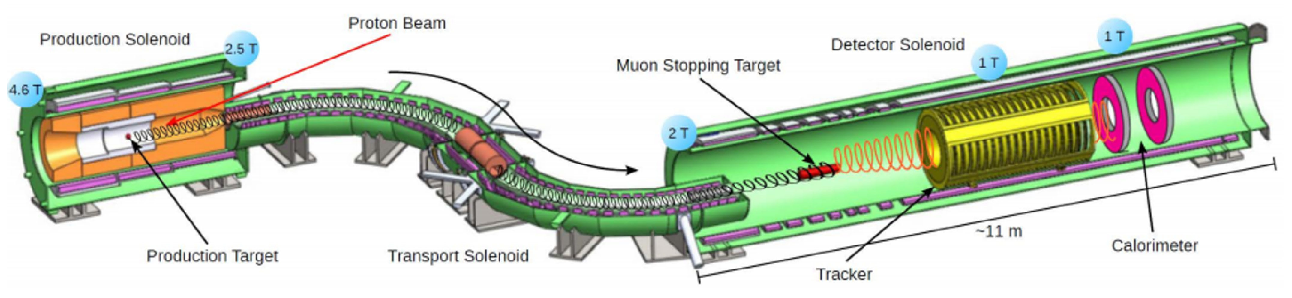
1. Introduction
2. Materials and Methods
2.1. Calorimeter Requirements
2.2. Technical Choices for Crystals and Photo-Sensors
2.3. Electronics Scheme
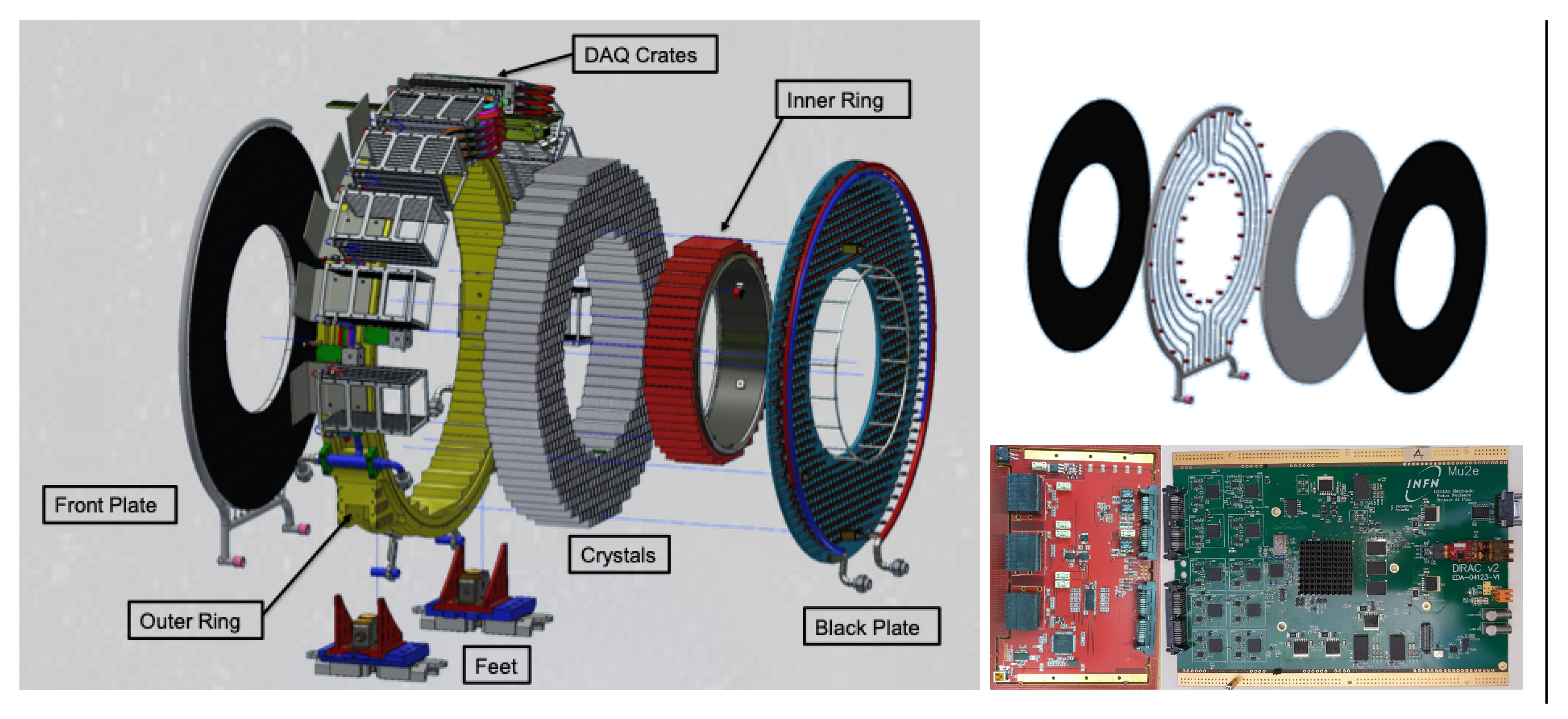
2.4. Breakdown of Mechanical Layout
2.5. Calibration Systems
3. Results
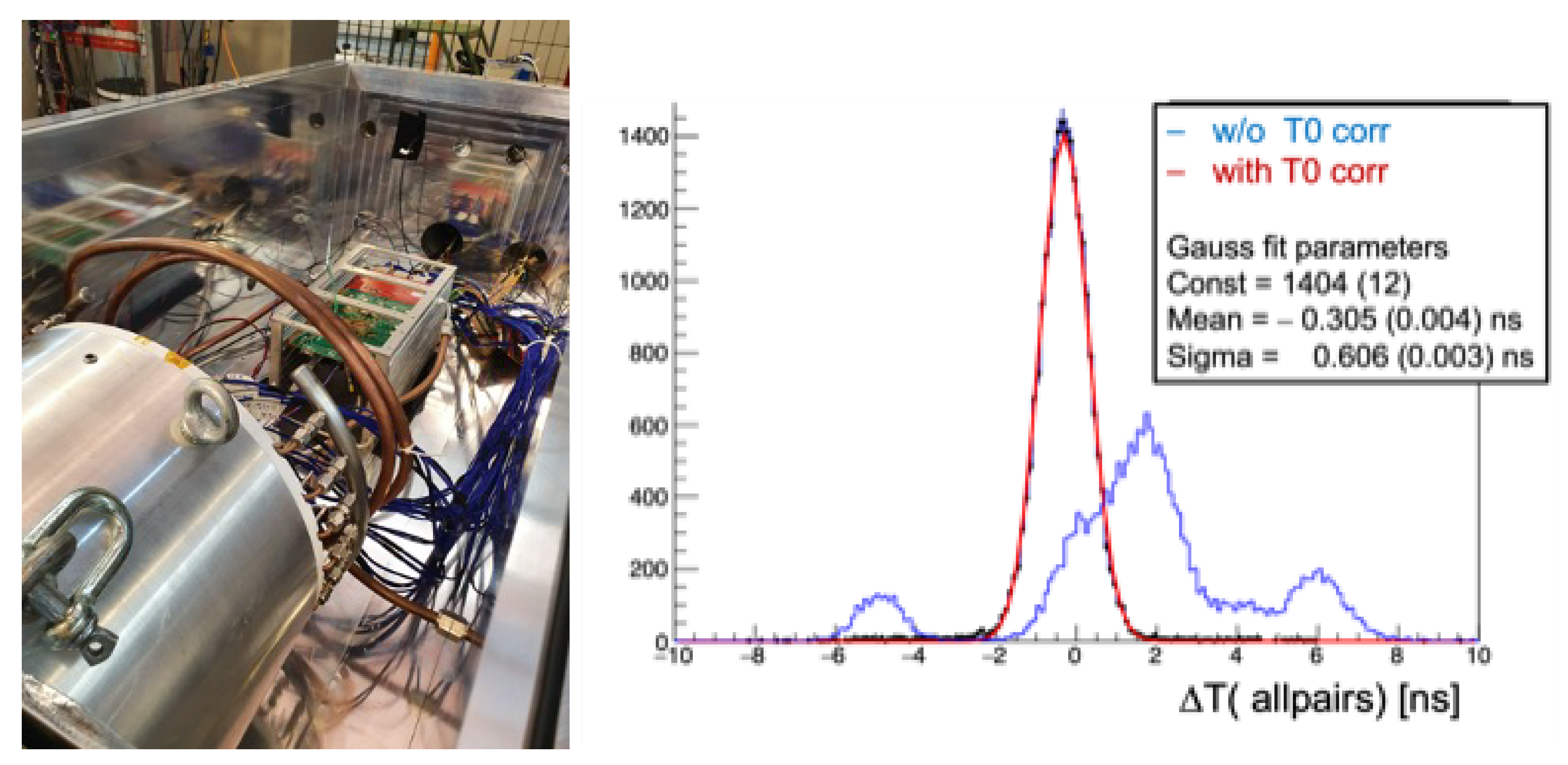
3.1. Calorimeter Qualification with Module-0
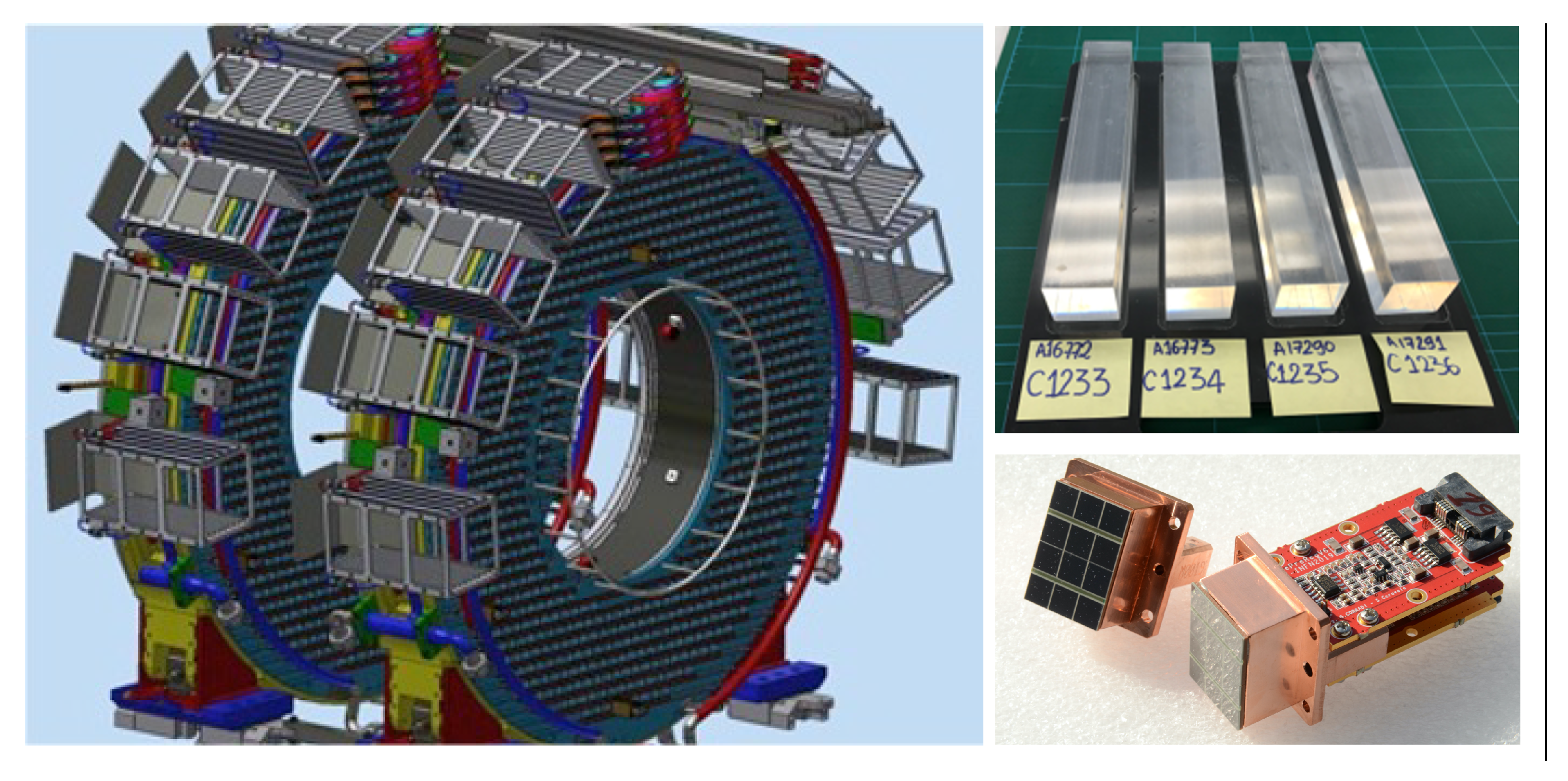
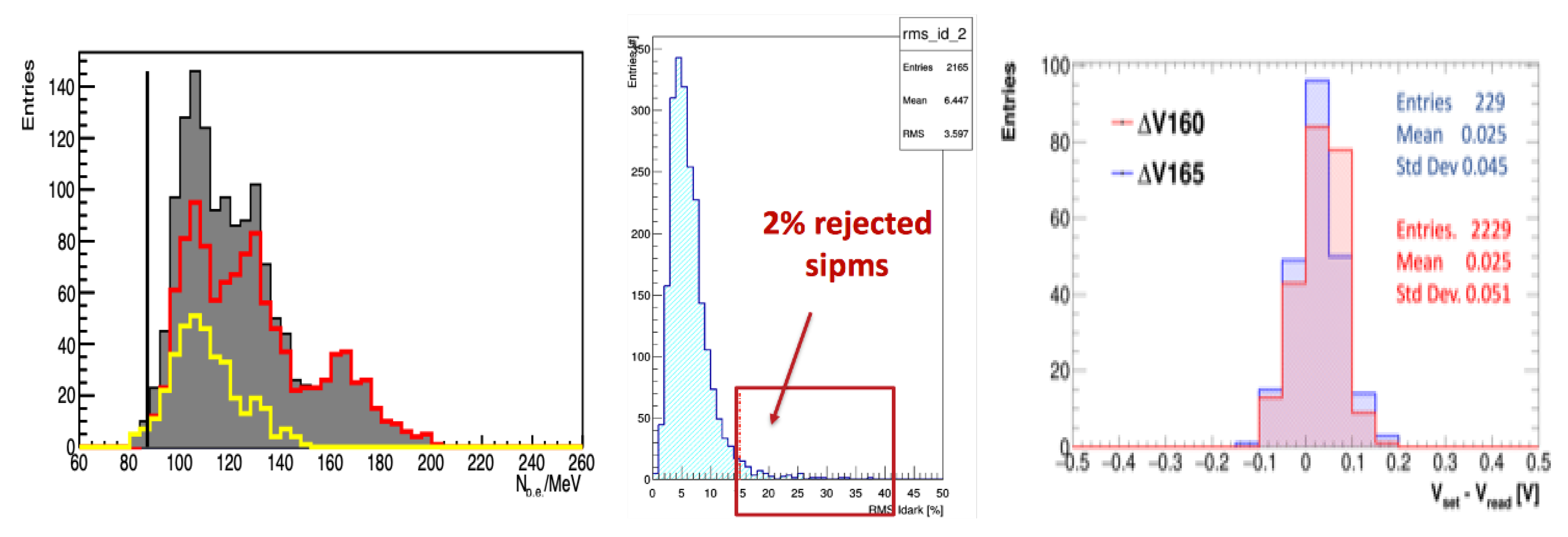
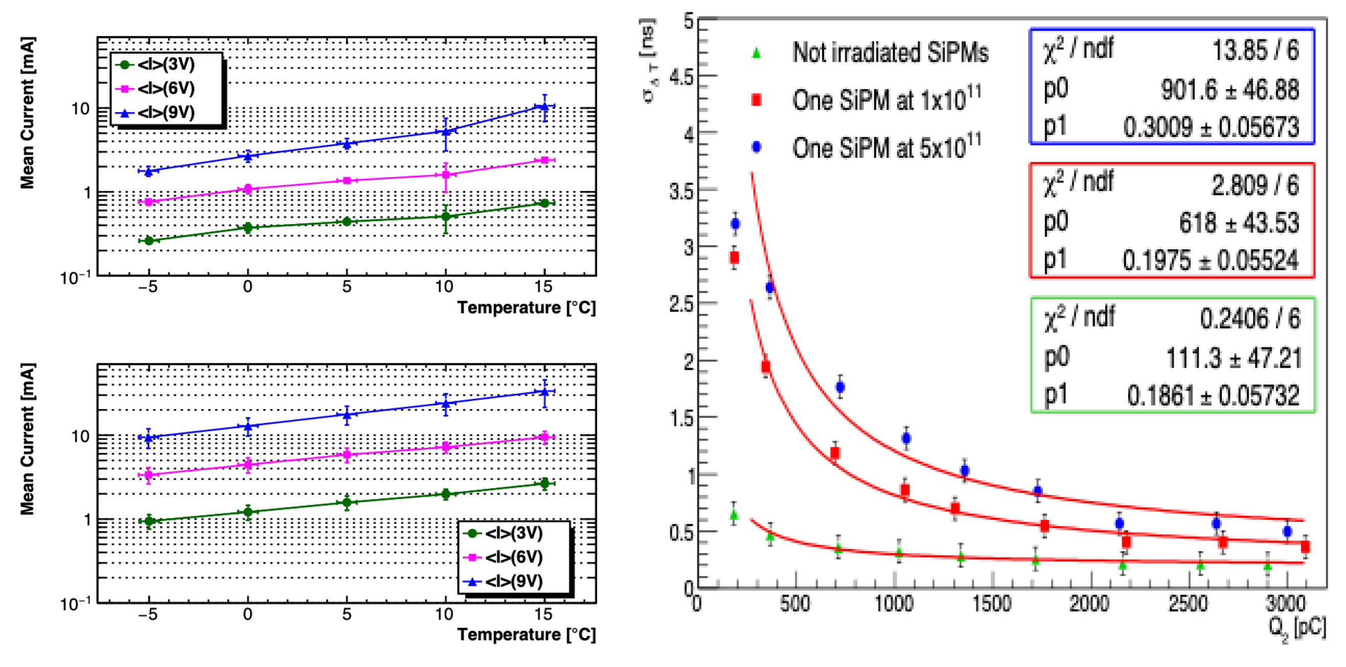
3.2. Production of Crystals, SiPMs and FEE
3.3. Preparation and Test of the Readout Units
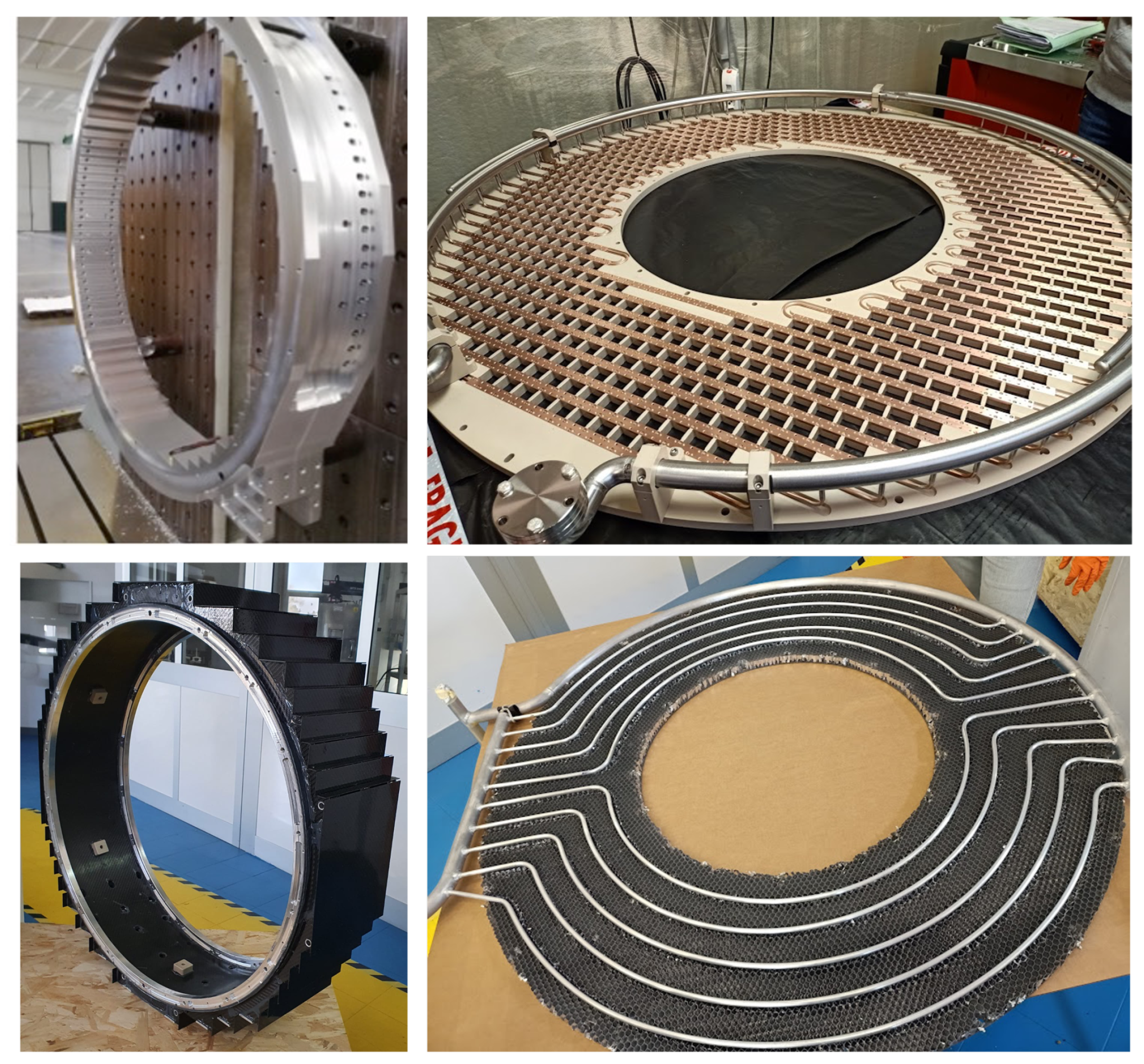
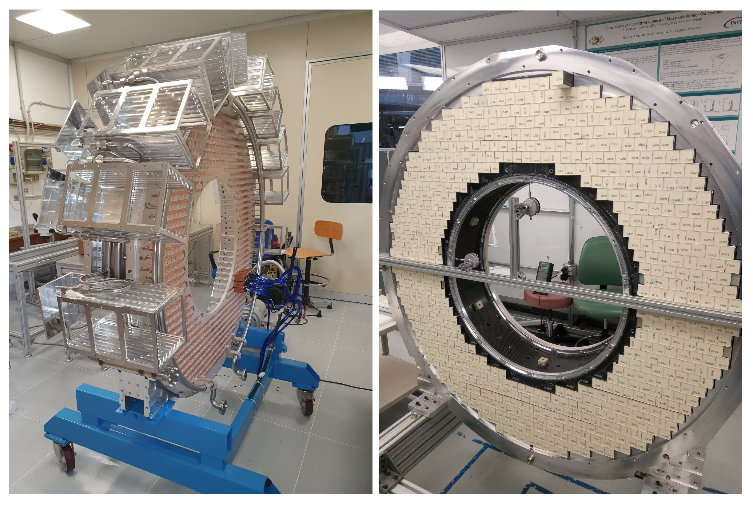
3.4. Production and Assembly of the Calorimeter Mechanical Structure
4. Discussion
5. Conclusions
Author Contributions
Funding
Data Availability Statement
Acknowledgments
Conflicts of Interest
References
- Bartoszek, L.; Barnes, E.; Miller, J.P.; Mott, J.; Palladino, A.; Quirk, J.; Roberts, B.L.; Crnkovic, J.; Polychronakos, V.; Tishchenko, V.; et al. The Mu2e Collaboration. Mu2e technical design report. arXiv 2015, arXiv:1501.05241. [Google Scholar]
- Bilenky, S.M.; Petcov, S.T.; Pontecorvo, B. Lepton mixing, μ→eγ decay and neutrino oscillations. Phys. Lett. B 1977, 67, 309–312. [Google Scholar] [CrossRef]
- Lobashev, V.; Djilibaev, R. On the search for μ→ e conversion on Nuclei. Sov. J. Nucl. Phys. 1989, 49, 384–385. [Google Scholar]
- Lee, M.J. Mu2e Collaboration. The straw tube tracker for the Mu2e experiment. Nucl. Phys. B Proc. Suppl. 2016, 273–275, 2530–2532. [Google Scholar]
- Atanov, N.; Baranov, V.; Bloise, C.; Budagov, J.; Cervelli, F.; Ceravolo, S.; Colao, F.; Cordelli, M.; Corradi, G.; Davydov, Y.I.; et al. Design and status of the Mu2e calorimeter. IEEE Trans. Nucl. Sci. 2018, 65, 2073–2080. [Google Scholar] [CrossRef]
- Artikov, A.; Baranov, V.; Blazey, G.C.; Chen, N.; Chokheli, D.; Davydov, Y.; Dukes, E.C.; Dychkant, A.; Ehrlich, R.; Francis, K.; et al. Photoelectron Yield od scintillating counters with embedded wavelength shifting fibers read out with silicon photomultipliers. Nucl. Instrum. Meth. A 2018, 890, 84–95. [Google Scholar] [CrossRef]
- Atanov, N.; Baranov, V.; Budagov, J.; Ceravolo, S.; Cervelli, F.; Colao, F.; Cordelli, M.; Corradi, G.; Dane, E.; Davydov, Y.; et al. The Mu2e calorimeter final design report. arXiv 2018, arXiv:1802.06341. [Google Scholar]
- Atanov, N.; Baranov, V.; Colao, F.; Cordelli, M.; Corradi, G.; Dane, E.; Davydov, Y.I.; Flood, K.; Giovannella, S.; Glagolev, V.; et al. Measurement of time resolution of the Mu2e LYSO calorimeter prototype. Nucl. Instrum. Meth. A 2016, 812, 104–111. [Google Scholar] [CrossRef]
- Atanov, N.; Baranov, V.; Colao, F.; Cordelli, M.; Corradi, G.; Dane, E.; Davydov, Y.I.; Flood, K.; Giovannella, S.; Glagolev, V.; et al. Energy and time resolution of a LYSO matrix prototype for the Mu2e experiment. Nucl. Instrum. Meth. A 2016, 824, 684–685. [Google Scholar] [CrossRef]
- Atanov, N.; Baranov, V.; Budagov, J.; Carosi, R.; Cervelli, F.; Colao, F.; Cordelli, M.; Corradi, G.; Dane, E.; Davydov, Y.I.; et al. Design and status of the Mu2e electromagnetic calorimeter. Nucl. Instrum. Meth. A 2016, 824, 695–698. [Google Scholar] [CrossRef]
- Ceravolo, S.; Colao, F.; Diociaiuti, E.; Corradi, G.; Di Falco, S.; Donati, S.; Fiore, S.; Ferrari, A.; Gioiosa, A. Design and qualification of the Mu2e electromagnetic calorimeter electronics system. In Proceedings of the 15th Pisa Meeting on Advanced Detectors, Isola d’Elba, Livorno, Italy, 22–27 May 2022. [Google Scholar]
- Atanov, N.; Baranov, V.; Borrel, L.; Bloise, C.; Budagov, J.; Ceravolo, S.; Cervelli, F.; Colao, F.; Cordelli, M.; Corradi, G.; et al. Mu2e crystal calorimetry front-end electronics: Design and characterization. In Proceedings of the Special Issue of Instruments 2022 Selected Papers from the 19th International Conference on Calorimetry in Particle Physics (Calor 2022), Brighton, UK, 16–20 May 2022. [Google Scholar]
- Atanov, N.; Baranov, V.; Borrel, L.; Bloise, C.; Budagov, J.; Ceravolo, S.; Cervelli, F.; Colao, F.; Cordelli, M.; Corradi, G.; et al. Development, construction and test of the Mu2e electromagnetic calorimeter mechanical structures. JINST 2022, 17, C01007. [Google Scholar] [CrossRef]
- Aubert, B.; Bazan, A.; Boucham, A.; Boutigny, D.; De Bonis, I.; Favier, J.; Gaillard, J.-M.; Jeremie, A.; Karyotakis, Y.; Le Flour, T.; et al. The BABAR detector. Nucl. Instrum. Meth. A 2002, 479, 1–116. [Google Scholar] [CrossRef]
- Atanov, N.; Baranov, A.; Budagov, A.; Caiulo, D.; Cervelli, F.; Colao, F.; Cordelli, M.; Davydov, Y.I.; Di Falco, S.; Diociaiuti, E.; et al. Design and test of the Mu2e un-doped CsI + SiPM crystal calorimeter. Nucl. Instrum. Meth. A 2019, 936, 94–97. [Google Scholar] [CrossRef]
- Atanov, N.; Baranov, V.; Budagov, J.; Davydov, Y.I.; Glagolev, V.; Tereshchenko, V.; Usubov, Z.; Cervelli, F.; Di Falco, S.; Donati, S.; et al. Quality assurance on un-doped CsI crystals for the Mu2e experiment. In Proceedings of the 2017 IEEE Nuclear Science Symposium and Medical Imaging Conference (NSS/MIC), Atlanta, GA, USA, 21–28 October 2017; pp. 752–757. [Google Scholar]
- Cordelli, M.; Cervelli, F.; Diociaiuti, E.; Donati, S.; Donghia, R.; Di Falco, S.; Ferrari, A.; Giovannella, S.; Happacher, F.; Martini, M.; et al. Pre-production and quality assurance of the Mu2e calorimeter Silicon Photomultipliers. Nucl. Instrum. Meth. A 2018, 912, 347–349. [Google Scholar] [CrossRef]
- Atanov, N.; Baranov, V.; Budagov, J.; Caiulo, D.; Cervelli, F.; Colao, F.; Cordelli, M.; Corradi, G.; Davydov, Y.I.; Di Falco, S.; et al. The Mu2e calorimeter: Quality assurance of production crystals and SiPMs. Nucl. Instrum. Meth. A 2019, 936, 154–155. [Google Scholar] [CrossRef]
- Sanzani, E.; Bloise, C.; Ceravolo, S.; Cervelli, F.; Colao, F.; Cordelli, M.; Corradi, G.; Falco, S.D.; Diociaiuti, E. An automated QC station for the calibration of the Mu2e calorimeter Readout Units. In Proceedings of the 1th Pisa Meeting on Advanced Detectors, Isola d’Elba, Livorno, Italy, 22–27 May 2022. [Google Scholar]


| Params | at 0 | at 50 | (ps) at 0 | (ps) at 50 |
|---|---|---|---|---|
| a | 0.6 | 0.6 | - | - |
| b | 0.27 (0.03) | 0.37 (0.04) | 6.8 (0.1) | 8.9 (0.2) |
| c | 4.05 (0.27) | 5.86 (0.39) | 91 (4) | 118 (7) |
Publisher’s Note: MDPI stays neutral with regard to jurisdictional claims in published maps and institutional affiliations. |
© 2022 by the authors. Licensee MDPI, Basel, Switzerland. This article is an open access article distributed under the terms and conditions of the Creative Commons Attribution (CC BY) license (https://creativecommons.org/licenses/by/4.0/).
Share and Cite
Atanov, N.; Baranov, V.; Borrel, L.; Bloise, C.; Budagov, J.; Ceravolo, S.; Cervelli, F.; Colao, F.; Cordelli, M.; Corradi, G.; et al. The Mu2e Crystal Calorimeter: An Overview. Instruments 2022, 6, 60. https://doi.org/10.3390/instruments6040060
Atanov N, Baranov V, Borrel L, Bloise C, Budagov J, Ceravolo S, Cervelli F, Colao F, Cordelli M, Corradi G, et al. The Mu2e Crystal Calorimeter: An Overview. Instruments. 2022; 6(4):60. https://doi.org/10.3390/instruments6040060
Chicago/Turabian StyleAtanov, Nikolay, Vladimir Baranov, Leo Borrel, Caterina Bloise, Julian Budagov, Sergio Ceravolo, Franco Cervelli, Francesco Colao, Marco Cordelli, Giovanni Corradi, and et al. 2022. "The Mu2e Crystal Calorimeter: An Overview" Instruments 6, no. 4: 60. https://doi.org/10.3390/instruments6040060
APA StyleAtanov, N., Baranov, V., Borrel, L., Bloise, C., Budagov, J., Ceravolo, S., Cervelli, F., Colao, F., Cordelli, M., Corradi, G., Davydov, Y., Falco, S. D., Diociaiuti, E., Donati, S., Echenard, B., Ferrari, C., Gioiosa, A., Giovannella, S., Giusti, V., ... Zhu, R. Y. (2022). The Mu2e Crystal Calorimeter: An Overview. Instruments, 6(4), 60. https://doi.org/10.3390/instruments6040060