Article

Split Hopkinson Tension Bar and Universal Testing Machine for High-Speed X-ray Imaging of Materials under Tension

1
INATECH-Sustainable Systems Engineering, Albert-Ludwigs-Universität Freiburg, Emmy-Noether Str. 2, 79110 Freiburg, Germany
2
Department of Physics, NRCN, P.O. Box 9001, Be’er Sheva 8419001, Israel
3
ESRF—The European Synchrotron, CS40220, CEDEX 09, 38043 Grenoble, France
4
Fraunhofer Institute for High-Speed Dynamics, Ernst-Mach-Institut, EMI, Ernst-Zermelo Str. 4, 79104 Freiburg, Germany
*
Author to whom correspondence should be addressed.
Instruments 2022, 6(3), 38; https://doi.org/10.3390/instruments6030038
Submission received: 5 August 2022 / Revised: 2 September 2022 / Accepted: 5 September 2022 / Published: 9 September 2022

Abstract

:
Studying the failure behaviour of engineered or natural materials under dynamic loading scenarios is of high importance, for example to investigate the fracture mechanics and to prevent catastrophic failures of constructions. When dynamic loading is coupled to high-speed X-ray imaging, not only surface information but images of the interior of the specimens during failure are accessible. Here, a custom designed Split Hopkinson Tension Bar (SHTB) coupled a Universal Testing Machine (UTM) has been developed, dedicated to study quasi-static and dynamic response using ultra-high speed X-ray phase contrast imaging. Both systems follow a compact design which allows them to be temporarily installed at a synchrotron beamline. A brief description of the installation and usage of these setups are outlined. Selected example applications outline the potential of these systems. Both systems can be considered for proposal experiments at beamline ID19 of the European synchrotron ESRF on request.

1. Introduction

Developments in the field of novel materials: From materials with complex microstructure to those designed to withstand significant deformations and be resilient, one requires in-depth knowledge of these materials deformation and fracture mechanics. Material response data from crash and impact loading situations are required for the design of lightweight, highly durable materials in the aerospace and automotive industries [1,2,3]. For such dynamic testing scenarios experimental systems based on the Kolsky bar become a natural choice. For a Kolsky bar experiment, one can determine the dynamic strain evolution by using one of the full field image analysis methods (e.g., Digital Image Correlation [4]). Similarly, high-speed cameras are employed to investigate the deformation history within transparent materials [5,6]. However, the comprehensive subsurface damage information is no longer apparent when the transparency is damaged during the deformation or when the specimens are optically opaque. Thus, X-rays deem as a suitable probe for imaging through-thickness failure of such specimens, exploring the interior damage processes.
In this paper we demonstrate the experimental advancements of custom-made dynamic and quasi-static traction setups customized to the capabilities of in situ ultra-high speed phase-contrast X-ray radiography at the European Synchrotron Radiation Facility (ESRF), Grenoble, France. This facility provides a unique opportunity for real-time in-situ X-ray imaging, allowing to visualise microstructural changes (e.g., pore formation and multi-fracture formation and propagation, as shown in Section 3) in the bulk of the specimen undergoing dynamic or quasi-static deformation. Propagation-based X-ray phase contrast imaging (XPCI) is used in real-time, resulting in improved contrast of material edges while preserving the material geometrical description. This is ensured by the careful arrangement of the pixel size, source energy and propagation distance (up to 10 m) within the near-field condition to ensure the image acquired resemble the true geometry of the specimen. Such imaging arrangement opens a plethora of possibilities to study the material micro-structural deformation ranging from void nucleation, high rate defect growth to different mechanically-induced failure mechanisms.
Development of 3rd and 4th generation high-energy synchrotron photon sources allowed the use of hard X-rays as diagnostics to probe matter during transient dynamics by capturing through volume information with high temporal and spatial resolution [7,8,9]. Mechanically induced dynamic failure can be followed across different material length scales using high-speed X-ray phase-contrast imaging, providing valuable insight into volume mechanisms occurring during material failure. Such diagnostics provides novel opportunities for in-depth study of the complex failure mechanisms in opaque materials under high strain rate using the Hopkinson pressure bar instruments, complementing the conventional macroscopic point-wise measurements by capturing the material under extreme loading scenarios. Some of the first applications focused on following the deformation and fracture mechanisms at micro scale (e.g., [10,11,12]). Recently focused studies, relying on a large field of view of millimetre scale, extend the study of materials under dynamic compression loading to spatial scales close-to representative elementary volume [13,14].
In this work, a Split-Hopkinson Tension bar (SHTB) for high rates of strain (500–5000 s−1) and a Universal Testing Machine (UTM) for low strain rate (10−3–1 s−1) were installed now at beamline ID19 of the ESRF. Owing to the available space of the experimental hutch, these devices were custom-built with the intention of extending the in-situ testing capabilities at ID19 to perform mechanical loading experiments covering a wide range of loading rates. The resulting strain rates are relevant to applications in automotive industry, aerospace crash scenarios as well as industrial processes such as metal sheet deep drawing and hydroforming.
The SHTB and UTM systems are designed for easy installation in the hutch. An aluminium frame on wheels, acts as a base to both the systems (interchangeable) which can be rolled in and out of the hutch in minutes. Figure 1 shows a sketch of the installation in the experimental hutch of ID19 including the SHTB.

2. Methods and Capabilities

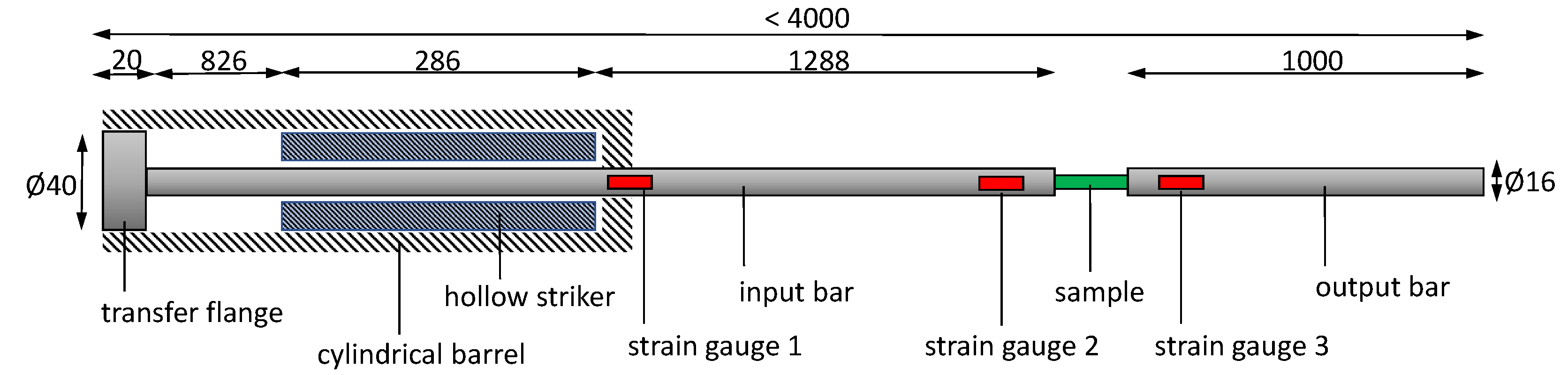
2.1. Split-Hopkinson Tension Bar

The Split-Hopkinson Tension Bar (SHTB) utilised in this work is sketched in Figure 2. This design configuration of the setup is intended to produce well-defined loading rates with precise force measurements at short time intervals. One of the key design issues was fitting the tension bar within the ID19 experimental hutch’s 5 m width (as shown in Figure 1) area. The dimensions of the setup are indicative of these conditions.
This design incorporates 16 mm diameter aluminium shafts as input bar and output bar cut to lengths 2400 mm and 1000 mm, respectively. Thus bringing the effective length of the whole system to sub 4 m length. The striker tube is a 286 mm long hollow polyoxymethylene shaft. With a wave propagation speed c 0 = 1400 m/s and the provided length of the striker, the effective pulse duration T = (2 × striker length)/ c 0 is about 0.41 ms. The cylindrical barrel horizontally supports the striker, which is pneumatically propelled by compressed air. A launching system is used to regulate the air pressure in the pressure tank, which is controlled remotely by the beamline control software. Circular specimens can be directly threaded to the bars and flat-sheet type specimens via constant impedance mount [15] for the bars. A pressure range of 0.3 bar to 2 bar corresponds to a velocity range of 2–15 m/s. At these controlled velocities, it is possible to perform high strain rate experiments in the order of 500–5000 s−1. A protective cover with clear windows made of polycarbonate encloses the specimen and contains its fragments, guaranteeing no harm to the other equipment in the hutch. The whole system is mounted on a height adjustable frame to align with the X-ray beam position.
Forces are measured using strain gauges installed on both bars and linked diagonally to a Wheatstone bridge circuit to exclude bending information. The output of the Wheatstone bridge is increased by a gain factor of 100 using an amplifier (excitation 10 V) with 1 MHz bandwidth. This signal is recorded with Teledyne Waverunner 8254M-MS oscilloscope with a bandwidth of 4 GHz.
The polychromatic beam energy spectrum used for X-ray imaging ranges from 20 keV to 50 keV with a mean energy of the beam ≈ 30 keV. During the dynamic experiments, a single crystal scintillator with a thickness of 500 µm of LYSO:Ce is employed to transform the transmitted X-ray photons into visible light that is recorded by a digital camera. Here, a HPV-X2 ultra-high speed camera (Shimadzu Cooperation, Kyoto, Japan) with 1× optical magnification captures, v i a a mirror, the luminescence images of the LYSO:Ce single-crystal scintillator (90 degree periscope design, to the keep electronics of the camera outside the intense X-ray radiation). A field-of-view (FOV) of 12.8 × 8 mm2 (maximum possible) is achieved by the detector with pixel resolution of 32 µm/pixel. Each recorded frame has a pixel count of 400 × 250 pixel. The detector continually records 128 frames in on-sensor memory, with the option of increasing the recording to 256 frames at lower pixel count each frame. The former can record at frame rates up-to 5 MHz, while the latter can record the frame rates up-to 10 MHz with inter-frame times as short as 50 ns. Within the 844.4 m long storage ring, ESRF provides filling modes that may be used for single bunch time resolved imaging with either 4-bunch (704 ns temporal spacing) or 16-bunch (176 ns temporal spacing) evenly spaced electron packets. The 16-bunch filling method is employed in the examples described here, with an inter flash time of X-ray arrival to the experimental hutch of 176 ns. The pulse width of each pulse impinging the deforming sample is approximately 100 ps, imposing the theoretical limit of the temporal resolution. In this work, 530 ns and 880 ns inter-frame temporal sampling is used at 200 ns exposure time to capture the full emission of the scintillator. A X-ray energy flux of 20 × 10 6 photons/mm2 is generated with 16-bunch filling mode at ID19 used for ultra-high-speed imaging. More information on bunch imaging and synchronised X-ray pulses at ESRF is discussed in [8,9].

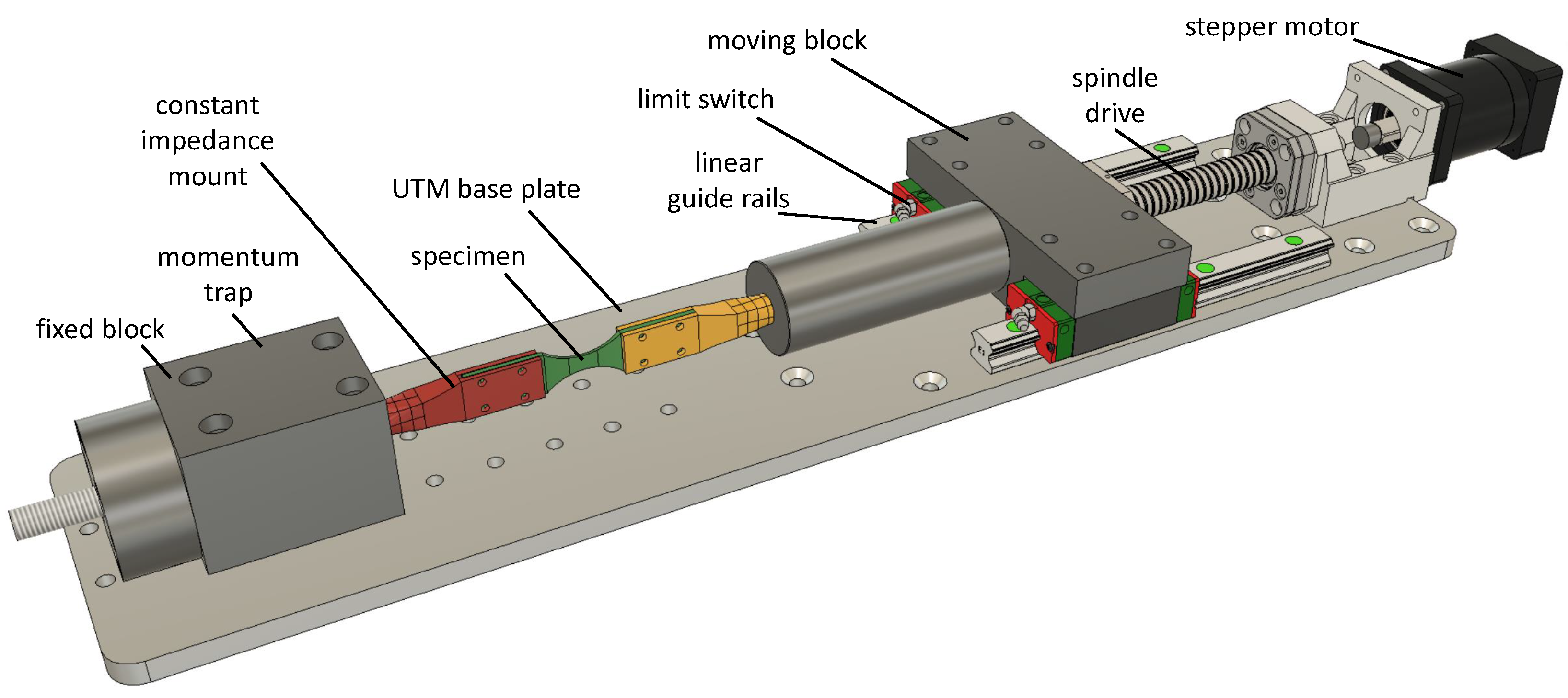
2.2. Universal Testing Machine

The Universal Testing Machine (UTM) employed in this work is shown in Figure 3. A stepper motor with planetary gears powers a spindle shaft in linear motion, allowing compression and tension tests to be performed. A maximum force of 10 kN can be achieved in compression or tension. Specimen mounts [15] are connected to fixed and moving blocks each. The UTM is less than 1 m in length and weighs only 5 kg. This portable device can be easily placed on to the height adjustable base frame of SHTB. The motion of the moving block is guided by linear rails and limit switches are employed at both ends of the rails to restrict the travel. The machine works at velocities ≈ 10 mm/s, corresponding to slow and quasi-static strain rates (10 3 –1 1 s).
The UTM is controlled via open source Arduino IDE software from the hutch control room. Protective case used for SHTB experiments can also be used with this machine to contain specimen fragments. A force sensor placed in the fixed block continuously records to the Arduino.
During slow tensile experiments, a single crystal scintillator LuAg: Ce is employed to convert X-rays to visible light that can be registered by the camera. Here, a high speed camera type SA-Z (Photron Ltd., Japan) lens-coupled to the scintillator captures the transmitted X-ray radiographs of a deforming sample. In this work two possible detector configurations were used. First, at 1× optical magnification-pixel pitch of 20 µm/pixel—with 500 µm thick LuAG:Ce scintillator. Second, at 2 × optical magnification-pixel pitch of 10 µm/pixel-with 250 µm thick LuAG:Ce scintillator. At a resolution of 1024 × 1024 pixel (with 23.3 µm exposure time) the camera records the deformation images at a frame rate of 10 kHz for ≈ 20 s recording duration. At ≈ 7 s of recording duration a higher frame rate of 200 kHz with a resolution of 384 × 176 pixel was achieved as well. The recording speed was adapted to the speed of the applied load.

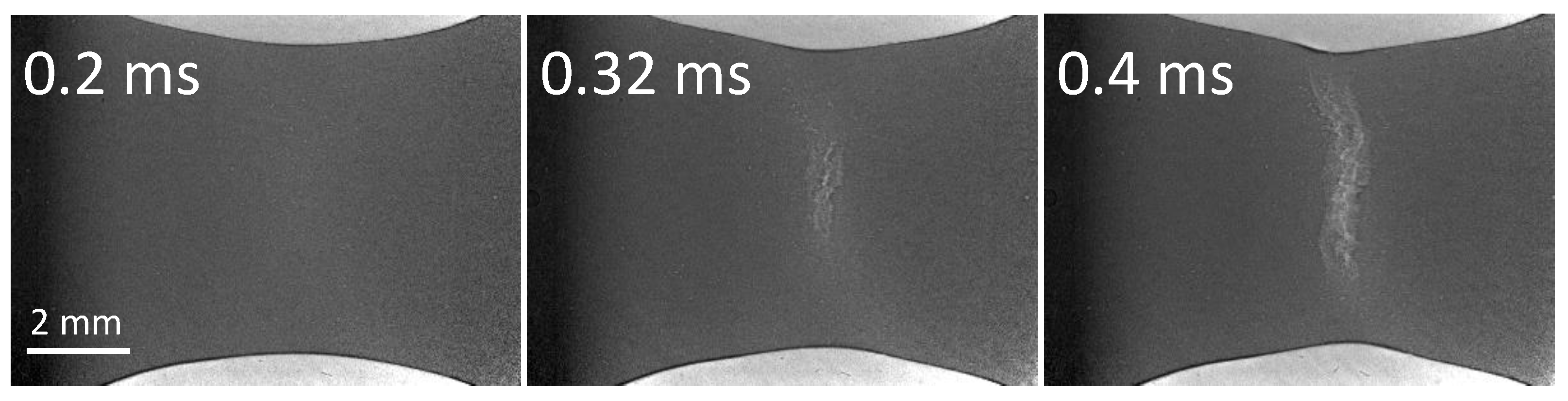
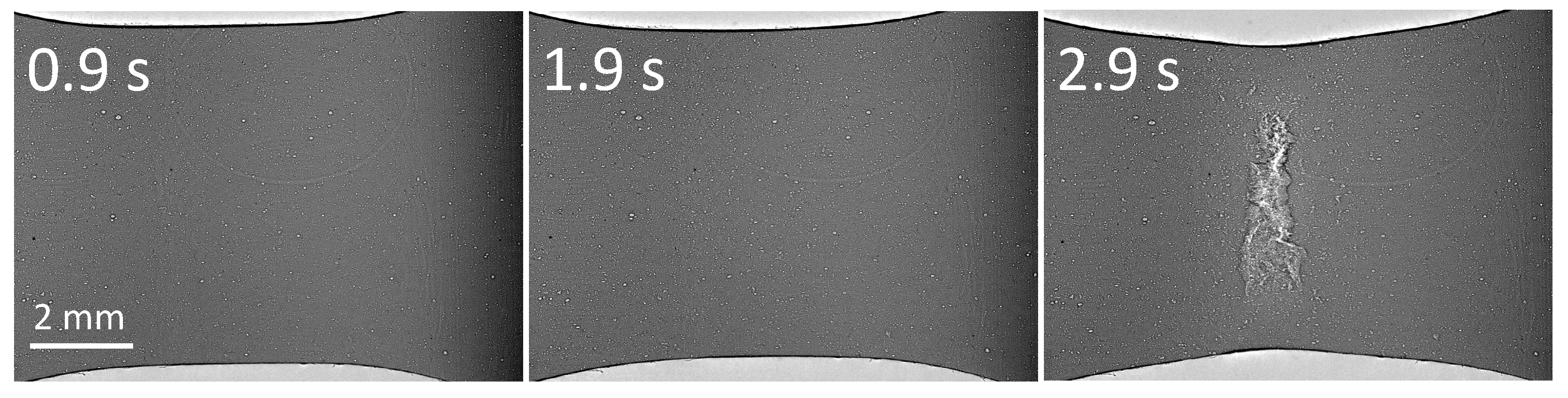
3. Example Applications

Dynamic and quasi-static tensile loading experiments were performed at ID19 on a series of composite and Additively Manufactured (AM) specimens. High strain rate dynamic experiments and slow quasi-static strain rate experiments were carried out at SHTB and UTM, respectively. Two unique materials have been selected for preliminary testing. Firstly, a Scandium modified Aluminium-Magnesium alloy AA5028 known as Scalmalloy serves for safety-relevant applications in the filed of crash and impact industry [16]. Specimen preparation and previous works on Scalmalloy can be found in [17,18]. Secondly, a high performance reinforced polymer composite, basalt-fibre reinforced polymer (BFRP) provides good fatigue resistance and energy absorption characteristics. Specimen preparation and previous works on BFRP can be found in [19,20].
Flat Scalmalloy specimens (printed 0°flat) with parallel gauge region of 7 × 3 mm2 (width × length) and a thickness of 1.5 mm, were tested in dynamic at a strain rate of 1000/s (shown in Figure 4) and quasi-static at a strain rate 0.001/s (shown in Figure 5). The specimens were produced as blanks of 100 × 23 × 3 mm3 (l × b × t) and then CNC milled to dimensions. The specimen geometry was designed to see the fracture in the gauge region and to work well with the constraints of our SHTB. Similarly to earlier works on Scalmalloy [17], this work indicates the typical behaviour of the material’s brittle nature, as the failure strains reach ≈ 10 %. Additionally, in both slow rate and high rate experiments, the crack initiates at the specimen’s centre and propagates towards the edges.
Basalt Fibre Reinforced Polymer (BFRP) specimens with fibre direction ±45° are prepared from prepregs of basalt fibres. The specimen dimensions are 20 × 3 × 1.6 mm3 (l × b × t). Figure 6 shows radiographs of deforming sample of the high strain rate dynamic experiments at a strain rate of 1000/s and Figure 7 are of the quasi-static experiments at a strain rate of 0.001/s. In both cases the fibre direction is clearly visible. In high strain rate experiments we observe an explosion of fibres, whereas, in low strain rate the fibres gradually fail, which is an expected phenomenon in fibre composites [20]. In all the above mentioned example applications, a clear depiction of the crack was achieved by XPCI: The image contains information from both attenuation (material thickness or density) and interference effects stemming from abrupt attenuation changes at interfaces causing white/black contrasts. Thus, the overall image is an attenuation image with enhanced edge contrast.
The force plots of the above mentioned specimens are shown in Figure 8. The maximum force of Scalmalloy and BFRP are 3.5 kN and 1.5 kN, respectively. Under compression and/or tension, the UTM can safely attain 10 kN of force amplitude. In SHTB a maximum force of 20 kN can be achieved with a particle velocity of 7.3 m/s, given the mechanical strength of the aluminium bars in the setup.

4. Summary

This study details the design of the installed SHTB and UTM systems at beamline ID19 of the ESRF (Grenoble, France). The capabilities of the two tensile testing methods have been demonstrated with two specimen trials in each system. As example application: Scalmalloy and BFRP, two distinct materials, were uniaxially probed under tension load at quasi-static and dynamic rates of strain. The deformation radiographic images of these specimens have been shown. The combination of the ESRF’s high-speed phase contrast radiography together with our experimental equipment offer an unique opportunity to investigate fracture behaviour in a wide range of materials from AM metals to reinforced polymers. Real-time in-situ imaging enables us to visualise microstructural changes, which is a very valuable information in the failure modelling of complex materials.

Author Contributions

Conceptualization, P.J. and G.G.; Data curation, P.J., A.C., D.L.-H. and G.G.; Formal analysis, P.J.; Funding acquisition, S.H.; Investigation, P.J. and B.L.; Resources, B.L. and A.R.; Supervision, A.R., G.G. and S.H.; Visualization, A.C. and G.G.; Writing—original draft, P.J.; Writing—review and editing, P.J., G.G., A.C., B.L. and A.R. All authors have read and agreed to the published version of the manuscript.

Funding

This research is funded from Carl-Zeiss Foundation, grant title Skalenübergreifende Charakterisierung robuster funktionaler Materialsysteme.

Acknowledgments

P.J. and G.G. gratefully acknowledge funding from Carl-Zeiss Foundation, grant title Skalenübergreifende Charakterisierung robuster funktionaler Materialsysteme. This work was performed at Beamline ID19 of the European Synchrotron Radiation Facility (ESRF) (BLC-13170), Grenoble, France for which we are grateful.

Conflicts of Interest

The authors declare no conflict of interest, in particular no financial or proprietary interests in any material discussed in this article.

References

  1. Ozdemir, Z.; Hernandez-Nava, E.; Tyas, A.; Warren, J.A.; Fay, S.D.; Goodall, R.; Todd, I.; Askes, H. Energy absorption in lattice structures in dynamics: Experiments. J. Impact Eng. 2016, 89, 49–61. [Google Scholar] [CrossRef]
  2. Tsouknidas, A.; Pantazopoulos, M.; Katsoulis, I.; Fasnakis, D.; Maropoulos, S.; Michailidis, N. Impact absorption capacity of 3D-printed components fabricated by fused deposition modelling. Mater. Des. 2016, 102, 41–44. [Google Scholar] [CrossRef]
  3. Li, S.; Zhao, S.; Hou, W.; Teng, C.; Hao, Y.; Li, Y.; Yang, R.; Misra, R.D.K. Functionally Graded Ti-6Al-4V Meshes with High Strength and Energy Absorption. Adv. Eng. Mater. 2016, 18, 34–38. [Google Scholar] [CrossRef]
  4. Gilat, A.; Schmidt, T.E.; Walker, A.L. Full Field Strain Measurement in Compression and Tensile Split Hopkinson Bar Experiments. Exp. Mech. 2009, 49, 291–302. [Google Scholar] [CrossRef]
  5. Chen, W.W.; Rajendran, A.M.; Song, B.; Nie, X. Dynamic Fracture of Ceramics in Armor Applications. J. Am. Ceram. Soc. 2007, 90, 1005–1018. [Google Scholar] [CrossRef]
  6. Paliwal, B.; Ramesh, K.T.; McCauley, J.W.; Chen, M. Dynamic Compressive Failure of AlON Under Controlled Planar Confinement. J. Am. Ceram. Soc. 2008, 91, 3619–3629. [Google Scholar] [CrossRef]
  7. Fezzaa, K.; Wang, Y. Ultrafast X-Ray Phase-Contrast Imaging of the Initial Coalescence Phase of Two Water Droplets. Phys. Rev. Lett. 2008, 100, 104501. [Google Scholar] [CrossRef] [PubMed]
  8. Rack, A.; Scheel, M.; Hardy, L.; Curfs, C.; Bonnin, A.; Reichert, H. Exploiting coherence for real-time studies by single-bunch imaging. J. Synchrotron Radiat. 2014, 21, 815–818. [Google Scholar] [CrossRef] [PubMed]
  9. Olbinado, M.P.; Just, X.; Gelet, J.L.; Lhuissier, P.; Scheel, M.; Vagovic, P.; Sato, T.; Graceffa, R.; Schulz, J.; Mancuso, A.; et al. MHz frame rate hard X-ray phase-contrast imaging using synchrotron radiation. Opt. Express 2017, 25, 13857. [Google Scholar] [CrossRef] [PubMed]
  10. Hudspeth, M.; Claus, B.; Dubelman, S.; Black, J.; Mondal, A.; Parab, N.; Funnell, C.; Hai, F.; Qi, M.L.; Fezzaa, K.; et al. High speed synchrotron x-ray phase contrast imaging of dynamic material response to split Hopkinson bar loading. Rev. Sci. Instruments 2013, 84, 025102. [Google Scholar] [CrossRef] [PubMed]
  11. Chen, W.W.; Hudspeth, M.C.; Claus, B.; Parab, N.D.; Black, J.T.; Fezzaa, K.; Luo, S.N. In situ damage assessment using synchrotron X-rays in materials loaded by a Hopkinson bar. Philos. Trans. R. Soc. A 2014, 372, 20130191. [Google Scholar] [CrossRef] [PubMed]
  12. Parab, N.D.; Claus, B.; Hudspeth, M.C.; Black, J.T.; Mondal, A.; Sun, J.; Fezzaa, K.; Xiao, X.; Luo, S.; Chen, W. Experimental assessment of fracture of individual sand particles at different loading rates. Int. J. Impact Eng. 2014, 68, 8–14. [Google Scholar] [CrossRef]
  13. Cohen, A.; Levi-Hevroni, D.; Fridman, P.; Chapman, D.; Rack, A.; Olbinado, M.P.; Yosef-Hai, A.; Eakins, D. In-situ radiography of a split-Hopkinson bar dynamically loaded materials. J. Instrum. 2019, 14, T06008. [Google Scholar] [CrossRef]
  14. Farbaniec, L.; Chapman, D.J.; Patten, J.R.W.; Smith, L.C.; Hogan, J.D.; Rack, A.; Eakins, D.E. In-situ visualisation of dynamic fracture and fragmentation of an L-type ordinary chondrite by combined synchrotron X-ray radiography and microtomography. Icarus 2021, 359, 114346. [Google Scholar] [CrossRef]
  15. Ganzenmüller, G.C.; Langhof, T.; Hiermaier, S. A Constant Acoustic Impedance Mount for Sheet-Type Specimens in the Tensile Split-Hopkinson Bar. EPJ Web Conf. 2018, 183, 02064. [Google Scholar] [CrossRef]
  16. Vorel, M.; Hinsch, S.; Konopka, M.; Scheerer, M. AlMgSc alloy 5028 status of maturation. In Proceedings of the 7th European conference for Aeronautics and Space Sciences (Eucass), Milan, Italy, 3–7 July 2017; Volume 633, p. 4. [Google Scholar] [CrossRef]
  17. Jakkula, P.; Ganzenmüller, G.; Gutmann, F.; Pfaff, A.; Mermagen, J.; Hiermaier, S. Strain Rate Sensitivity of the Additive Manufacturing Material Scalmalloy®. J. Dyn. Behav. Mater. 2021, 7, 518–525. [Google Scholar] [CrossRef]
  18. Koutny, D.; Skulina, D.; Pantělejev, L.; Paloušek, D.; Lenczowski, B.; Palm, F.; Nick, A. Processing of Al-Sc aluminum alloy using SLM technology. Procedia Cirp 2018, 74, 44–48. [Google Scholar] [CrossRef]
  19. Plappert, D.; Ganzenmüller, G.C.; May, M.; Beisel, S. Mechanical Properties of a Unidirectional Basalt-Fiber/Epoxy Composite. J. Compos. Sci. 2020, 4, 101. [Google Scholar] [CrossRef]
  20. Ganzenmüller, G.C.; Plappert, D.; Trippel, A.; Hiermaier, S. A Split-Hopkinson Tension Bar study on the dynamic strength of basalt-fibre composites. Compos. Part Eng. 2019, 171, 310–319. [Google Scholar] [CrossRef]
Figure 1. Schematic experimental setup showing-X-ray beam, Hopkinson bar and ID19 hutch.
Instruments 06 00038 g001
Figure 2. Sketch of the SHTB setup employed in this work. All dimensions are in mm. Input and output bars are 16 mm diameter aluminium rods. The striker is a hollow POM tube of 40 mm outer diameter and 16.1 mm inner diameter. Two strain gauges on the input bar to measure the incident wave [ ε i n c ] and reflected wave [ ε r e f ], and one on output bar to measure the transmitted wave [ ε t r a ].
Instruments 06 00038 g002
Figure 3. Sketch of the UTM setup employed in this work.
Instruments 06 00038 g003
Figure 4. X-ray images of Scalmalloy specimen (printed 0° flat) under tension in SHTB. Image series captured by Shimadzu HPV-x2 based ultra-high speed X-ray detector at 1.14 MHz frame rate (with 880 ns inter-frame temporal sampling and captured with an exposure time of 200 ns) and a pixel count of 400 × 250 pixels for each of 128 acquired frames. From left to right, different timestamps capturing the formation of crack to fracture. White contrast in these radiographs represent high intensity X-rays. The aspect ratio of the images are adjusted for illustration purposes.
Instruments 06 00038 g004
Figure 5. X-ray images of Scalmalloy specimen (printed 0° flat) under tension in quasi-static UTM. Image series captured by Photron SA-Z high speed camera at 10 kHz frame rate and a resolution of 1024 × 1024 pixels. From left to right, different timestamps capturing the formation of voids to fracture. White contrast in these radiographs represent high intensity X-rays. The aspect ratio of the images are adjusted for illustration purposes.
Instruments 06 00038 g005
Figure 6. X-ray images of Basalt Fibre BFRP (fibre direction ±45°) under tension in SHTB. Image series captured by Shimadzu HPV-x2 based ultra-high speed X-ray detector at 1 MHz frame rate (with 1060 ns inter-frame temporal sampling and captured with an exposure time of 200 ns) and a pixel count of 400 × 250 pixels for each of 128 acquired frames. From left to right, different timestamps capturing the formation of crack to fracture. White contrast in these radiographs represent high intensity X-rays. The aspect ratio of the images are adjusted for illustration purposes.
Instruments 06 00038 g006
Figure 7. X-ray images of Basalt Fibre BFRP (fibre direction ±45°) under tension in quasi-static UTM. Image series captured by Photron SA-Z high speed camera at 10 kHz frame rate and a resolution of 1024 × 1024 pixels. From left to right, different timestamps capturing the formation of crack to fracture. White contrast in these radiographs represent high intensity X-rays. The aspect ratio of the images are adjusted for illustration purposes.
Instruments 06 00038 g007
Figure 8. Force analysis of Scalmalloy (printed 0° flat) and Basalt Fibre BFRP (fibre direction ±45°) under tension in dynamic and quasi-static tension experiments. All results presented here, are a set of two experiments.
Instruments 06 00038 g008
Publisher’s Note: MDPI stays neutral with regard to jurisdictional claims in published maps and institutional affiliations.

