Article

Micromagnetic Simulation of Round Ferromagnetic Nanodots with Varying Roughness and Symmetry

Faculty of Engineering and Mathematics, Bielefeld University of Applied Sciences, 33619 Bielefeld, Germany
*
Author to whom correspondence should be addressed.
Condens. Matter 2021, 6(2), 19; https://doi.org/10.3390/condmat6020019
Submission received: 23 March 2021 / Revised: 21 May 2021 / Accepted: 24 May 2021 / Published: 26 May 2021
(This article belongs to the Section Magnetism)

Abstract

:
Magnetic nanodots are of high interest for basic research due to their broad spectrum of possible magnetic states and magnetization reversal processes. Besides, they are of technological interest since they can be applied in magnetic data storage, especially if vortex states occur in closed dots or open rings. While producing such nanorings and nanodots from diverse magnetic materials by lithographic techniques is quite common nowadays, these production technologies are naturally prone to small deviations of the borders of these nanoparticles. Here we investigate the influence of well-defined angular-dependent roughness of the edges, created by building the nanoparticles from small cubes, on the resulting hysteresis loops and magnetization reversal processes in five different round nanodots with varying open areas, from a thin ring to a closed nanodot. By varying the orientation of the external magnetic field, the impact of the angle-dependent roughness can be estimated. Especially for the thinnest ring, significant dependence of the transverse magnetization component on the field orientation can be found.

1. Introduction

Round magnetic nanodots, either closed or ring-like, have been investigated by many research groups. Besides relative ease to produce them reliably with lithographic methods, they are mostly interesting due to the vortex states occurring in dots of diverse dimensions [1,2]. Vortex states generally have low in-plane stray fields, resulting in small, although not fully negligible interactions with neighboring nanodots [3]. Their chirality—whether the magnetization rotates clockwise or counterclockwise—can be used to store data. For closed nanodots, the vortex core polarity, pointing up or down, can also be used to store data [4]. This is why several research groups investigated possibilities to reverse the vortex polarity [5,6,7,8,9] or possible eigenmodes of vortex precessions [10,11,12].
The nucleation of vortex states and possible propagation of the vortex cores generally depend on the geometry and on the anisotropies within a nanodot. Modifying the anisotropy along the nanodot, for example, can result in deformations of the vortex core [13]. Embedding nanodots from hard magnetic materials into a matrix of soft magnetic material or vice versa can result in “large” vortices along neighboring nanodots or regular ones, limited to single nanodots [14], while bow-tie shape nanodots in a magnetic matrix can result in double-vortices, depending on geometry and material combination [15].
The influence of the nanodot thickness on nucleation and annihilation fields for a vortex state was even revealed in an array of CoFe nanodots with varying thickness [16]. Varying the geometry further, sometimes double-vortex states were found in nanodots consisting of only one material [17,18,19,20].
Besides these studies dealing with filled nanodots, there are also several reports on open nanorings. Zhang and Haas found the switching mechanisms in such nanorings to depend on the relative geometrical dimensions, especially showing vortex, onion, and double vortex states. They also found 360° domain walls, called twists [21]. Similarly, Yoo et al. found onion and vortex states in magneto-optical Kerr effect measurements and the phase border between them to depend on thickness, ring width, and external diameter [22]. Vaz et al. investigated a broad range of features found in magnetic nanorings, from electric currents used to shift domain walls to pinning of domain walls at size constrictions [23].
A more detailed study on different domain walls in magnetic nanorings prepared from permalloy was performed by Park et al. who found single- and double-vortex head-to-head domain walls for different ring thicknesses [24]. Most recently, Muscas et al. investigated mesoscale magnetic rings by first-order reversal curves (FORC) and revealed the aforementioned typical metastable states, i.e., onion and vortex states, and found transverse and vortex domain walls in the onion configurations [25].
A factor occurring in all experimental investigations, but often being neglected, is the indispensable roughness along the outer and, in case of nanorings, also inner edges, since lithographic production processes can naturally not lead to perfectly flat edges [26]. Such edge defects and roughness are known to result in pinning of domain walls and thus in an increase of coercivity [27,28,29]. Studies of the influence of border roughness on magnetic states and magnetization reversal processes, however, are scarce. Madami et al. investigated the impact of roughness and polycrystallinity on magnetic nanodots used as switches in spintronics devices and found increased energy dissipation due to these imperfections [30]. Tu et al. also saw an influence of the edge roughness on the magnetic properties of nanodots, prepared by different techniques [31].
Here, we investigate the effect of a small edge roughness, below the accuracy of recent lithographic techniques, on magnetization reversal in symmetric nanodots and nanorings and compare it with the influence of a highly asymmetric open area in a nanoring. Simulations of the roughness are performed by modelling the nanodots and nanorings by small cubes and rotating the external magnetic field successively to investigate whether differences occur in the magnetization reversal of the otherwise completely symmetric nanodots and nanorings.

2. Materials and Methods

The simulation program OOMMF (Object Orientated MicroMagnetic Framework) [32] was used to run all micromagnetic simulations in this work. OOMMF is based on solving the Landau-Liftshitz-Gilbert equation [33] and runs on CPU cores, other than mumax3 which works on GPUs [34].
For all simulations, nanoparticles of iron were used. Therefore, literature values of iron (Fe) were chosen as parameters of the material: MS,Fe = 1700 × 103 A/m as magnetization at saturation, AFe = 21 × 10−12 J/m as exchange constant and K1,Fe = 48 × 103 J/m3 as magneto-crystalline anisotropy constant [35]. The Gilbert damping constant was chosen with a value of α = 0.5 to represent the quasistatic case.
The crystalline orientation chosen was “random”, modelling the typical situation of sputtered nanostructures. The cubic grain size was set to (5 nm)3 unless mentioned differently.
The external magnetic field was swept from 250 mT to −250 mT and back in 1000 steps per direction, i.e., with a field step size of ΔH = 0.5 mT, unless denoted differently. These field strengths were sufficient to always reach magnetization saturation. Besides longitudinal (ML) and transversal magnetization components (MT), spatially resolved screenshots were taken to investigate the magnetic states and magnetization reversal processes. The simulations were performed at angles θ of the external magnetic field from 0° to 90° at intervals of 15°.
The shapes used in the simulations, depicted in Figure 1, have diameters of 500 nm and a height of 5 nm, combined with different symmetric cutouts (Figure 1a–c), without cutout (Figure 1d), or with an asymmetric cutout (Figure 1e) as a comparison. Figure 1f shows the definition of the angles in this study. Case 1 is a very fine ring; a disk of diameter 460 nm has been cut out. Case 2 is slightly broader, a dot with diameter 350 nm has been cut. Case 3 is almost a disk with a hole in the center of diameter 55 nm. Case 4 is solid. The cylinder that is punched out of case 5 is 275 nm in diameter and eccentric.
All simulated hysteresis loops, combined with six snapshots of the magnetization reversal process per simulation, are depicted in the Supplementary Information.

3. Results and Discussion

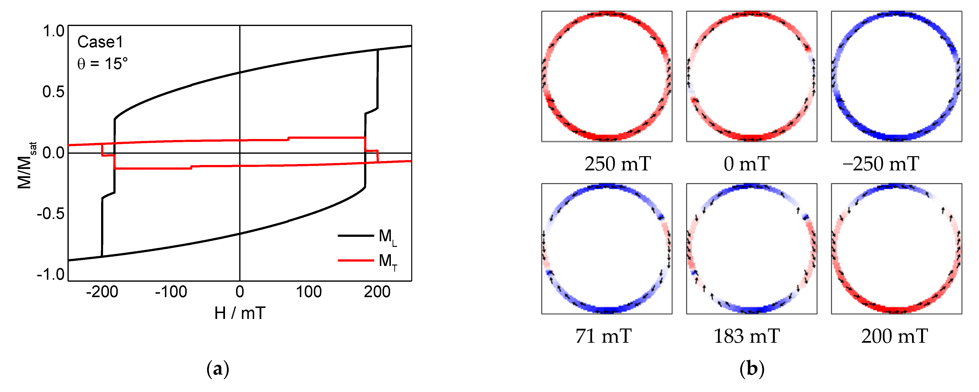
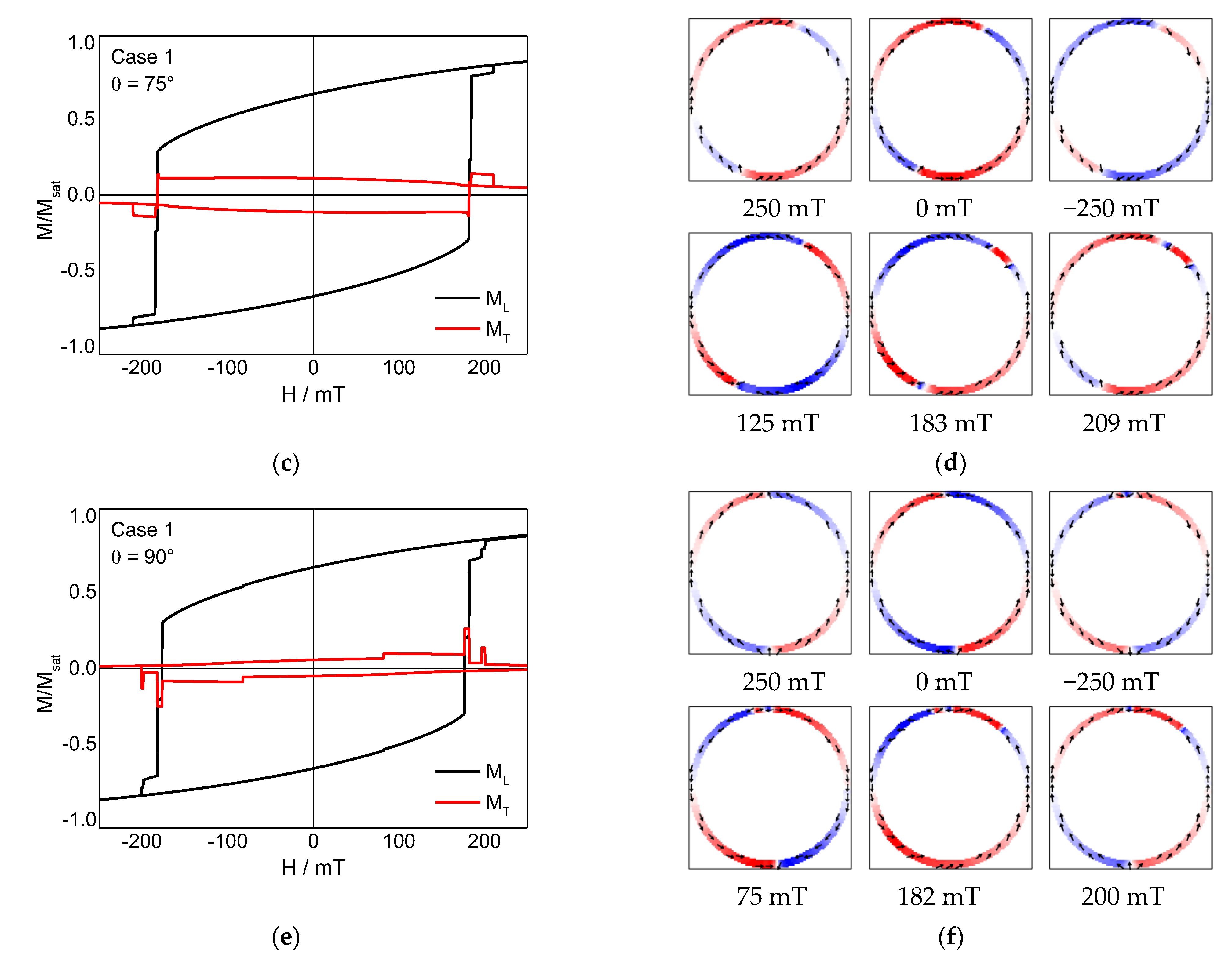
Figure 2 depicts the results of some chosen angles, simulated for case 1. Generally, the first three snapshots show positive saturation (250 mT), 0 mT, and negative saturation (−250 mT), while the next three snapshots show characteristic points during the reversed field sweep from negative to positive saturation.
Comparing these hysteresis loops shows on the one hand that the coercivities are quite similar and apparently stable against the rotation of the external magnetic field. The loop shapes, however, differ. On the one hand, the steps in the longitudinal loops have different heights; on the other hand, the transverse magnetization loops show clearly different shapes. It should be mentioned that even the transverse magnetization at saturation, which would be expected to be equal to zero for a fully symmetric system [36], is apparently smaller or larger than zero, depending on the orientation. This indicates that the introduced edge roughness also introduced an anisotropy, which will be investigated quantitatively at the end of this paper. Comparing the transverse magnetization at saturation with a simulation [32] gives rise to an additional fourfold anisotropy here.
It should be mentioned that opposite to other simulations, the highly symmetric orientations θ = 0° etc. do not show hysteresis loops and magnetic states qualitatively different from neighboring orientations like 1°. As visible here for θ = 90°, magnetization reversal starts with an onion state, which is also the case for θ = 91°, θ = 92° etc. Only the position of the domain walls at the “beginning” and “end” of the onion state is slightly shifted according to the field orientation.
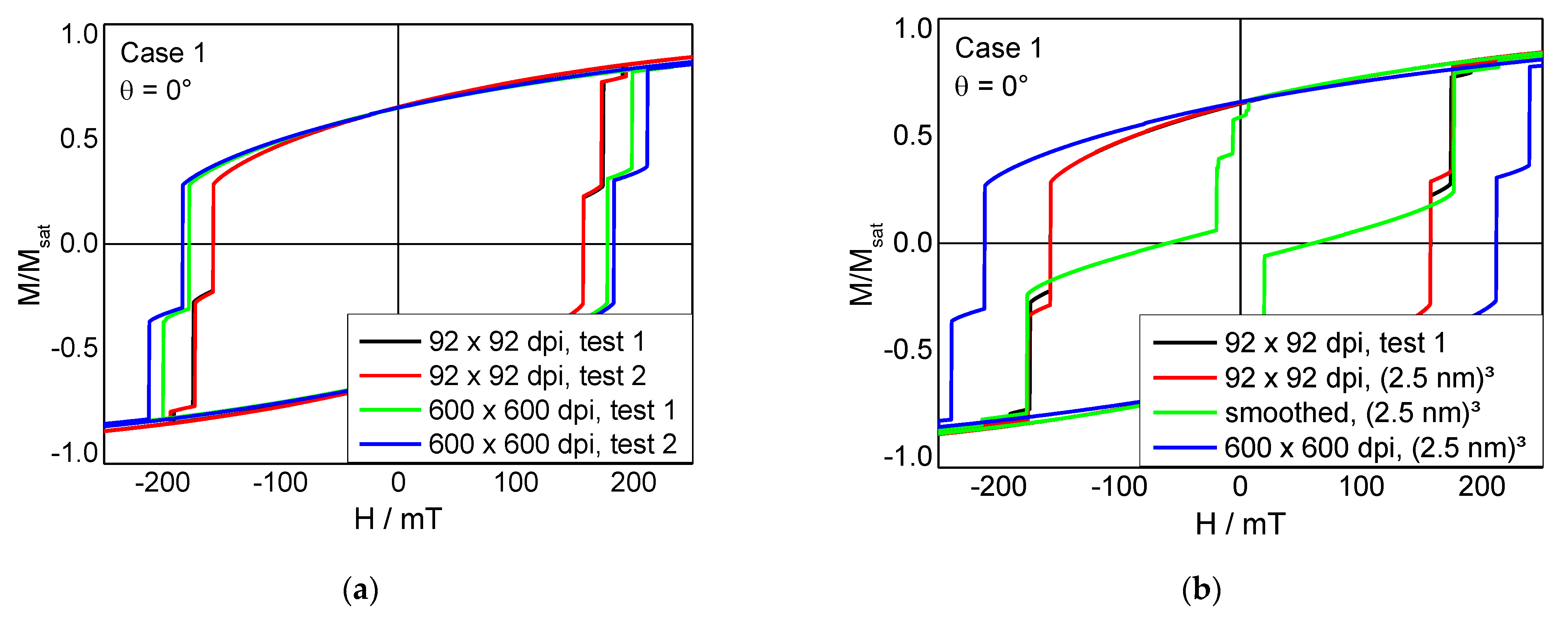
Besides, it should be investigated whether the anisotropy visible here is influenced by the cell size, with and without changing the edge roughness at the same time. For this, different sample and simulation parameters were changed. Figure 3a shows two tests each, performed with the original mask (600 × 600) dpi and a cell size of 5 nm, i.e., splitting the image in (92 × 92) cells laterally inside OOMMF, and performed on a mask which was reduced to (92 × 92) dpi before using it in OOMMF. While the two corresponding graphs are similar (in case of (600 × 600) dpi) or nearly equal (in case of the pre-defined mask with (92 × 92) dpi), there is a clear difference visible between (92 × 92) dpi and (600 × 600) dpi masks. This can be attributed to several pixels (here identical to cells) being either filled with magnetic material or not along the edges of this structure. In this quite narrow ring, even single pixels can make a difference, as this experiment shows. Generally, however, the slopes of the loops as well as the magnetization reversal processes are similar and identical to those depicted in Figure 2f.
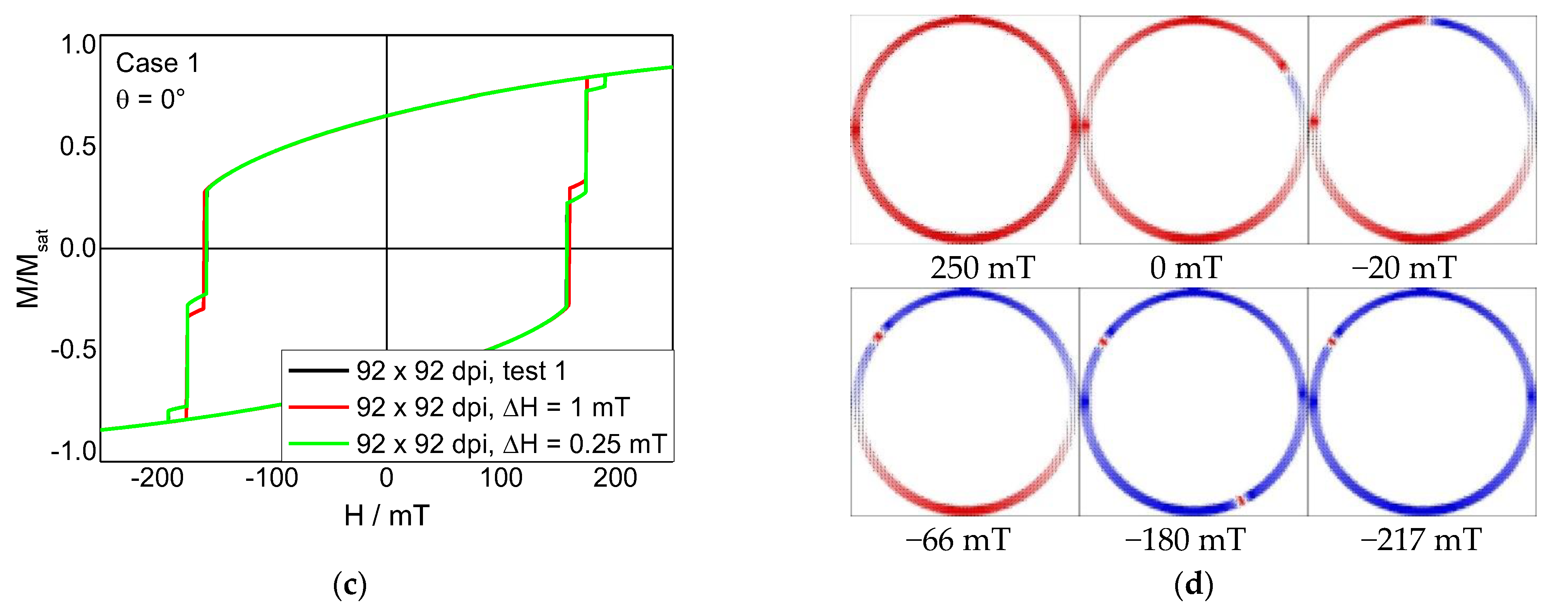
Next, Figure 3b shows a comparison of the curve for (92 × 92) dpi, used as a reference, with the same mask, simulated with a halved cell size of 2.5 nm. Both are nearly identical, with the step around −160 mT to −170 mT having a slightly different height due to a slightly different position of the remaining domain wall in this field range. Next, the green graph shows results of a simulation with “smoothed” edges, where the mask was reduced from (600 × 600) dpi to (92 × 92) dpi with jpg smoothing. Such light-grey areas are interpreted by OOMMF as thinner regions. Unexpectedly, this curve has a completely different slope. It results from the magnetization reversal mechanism depicted in Figure 3d. Here, the domain wall firstly located near the right end of the sample starts moving to the top, moves on to the left until the domain wall at the left vanishes, the lower left part of the sample switches by creating a new domain wall on the lower right side, which vanishes again, before finally the moving domain wall vanishes, too. Apparently, such “thinned” edges do not fix domain walls as strongly as the original shape. This feature will be investigated by a better defined edge thinning in the future.
The last graph in Figure 3b was simulated by using the original (600 × 600) dpi image as mask, but again with a cell size of (2.5 nm)3. This curve again looks quantitatively different from the former curves. Comparing it with both curves simulated with the (92 × 92) mask without edge thinning, it can be stated that no large difference is visible between cell sizes of (5 nm)3 and (2 nm)3, but reducing the edge roughness quantitatively (not qualitatively) changes the hysteresis loops.
Finally, Figure 3c shows a comparison of simulations performed with different ΔH. Similar to experimental investigations where the field switching speed can clearly alter the measured hysteresis loops, here also small differences between ΔH = 0.25 mT from positive to negative saturation, ΔH = 0.5 mT and ΔH = 1 mT are visible. However, these differences are only quantitative; no qualitative changes of magnetization reversal processes are visible.
Due to these finding, the next simulations were proceeded with the parameters mentioned in Section 2.
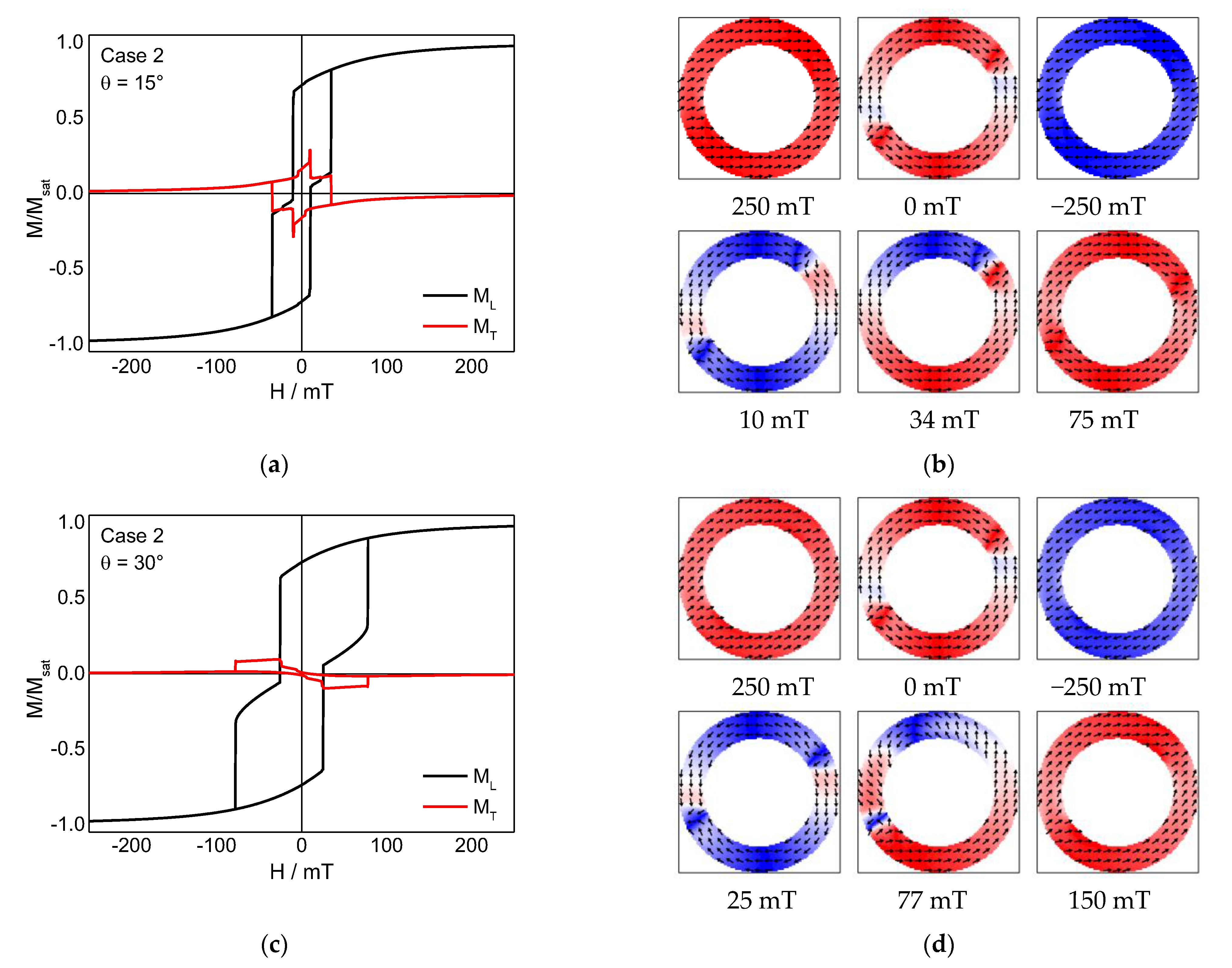
When comparing different angles θ simulated for case 2, it could be expected that the broader ring is less influenced by a small surface roughness. As Figure 4 shows, this is correct in terms of the transverse magnetization at saturation, which is near zero for all angles under examination. Nevertheless, for case 2 not only the transverse, but also the longitudinal hysteresis loops differ strongly for different field angles θ. Comparing the magnetization snapshots of θ = 15° and θ = 30° orientations (Figure 4b,d) gives a possible explanation for this finding. In both cases, a horseshoe-like state is visible (10 mT for θ = 15° and 25 mT for θ = 30°, respectively), followed by a vortex state with 360° domain wall (34 mT for for θ = 15° and 77 mT for θ = 30°). These 360° domain walls, however, are not found along the symmetry axis of θ = 15° or θ = 30°, respectively, and are generally shifted from this expected orientation. This fits to the aforementioned findings that the edge roughness can produce pinning centers for domain walls [27,28,29], leading to deviations from the expected symmetry due to the external magnetic field orientation and thus variations of the coercive fields. It should be mentioned that no clear correlation between field orientation and coercive fields could be identified for case 2 (cf. Supplementary Information).
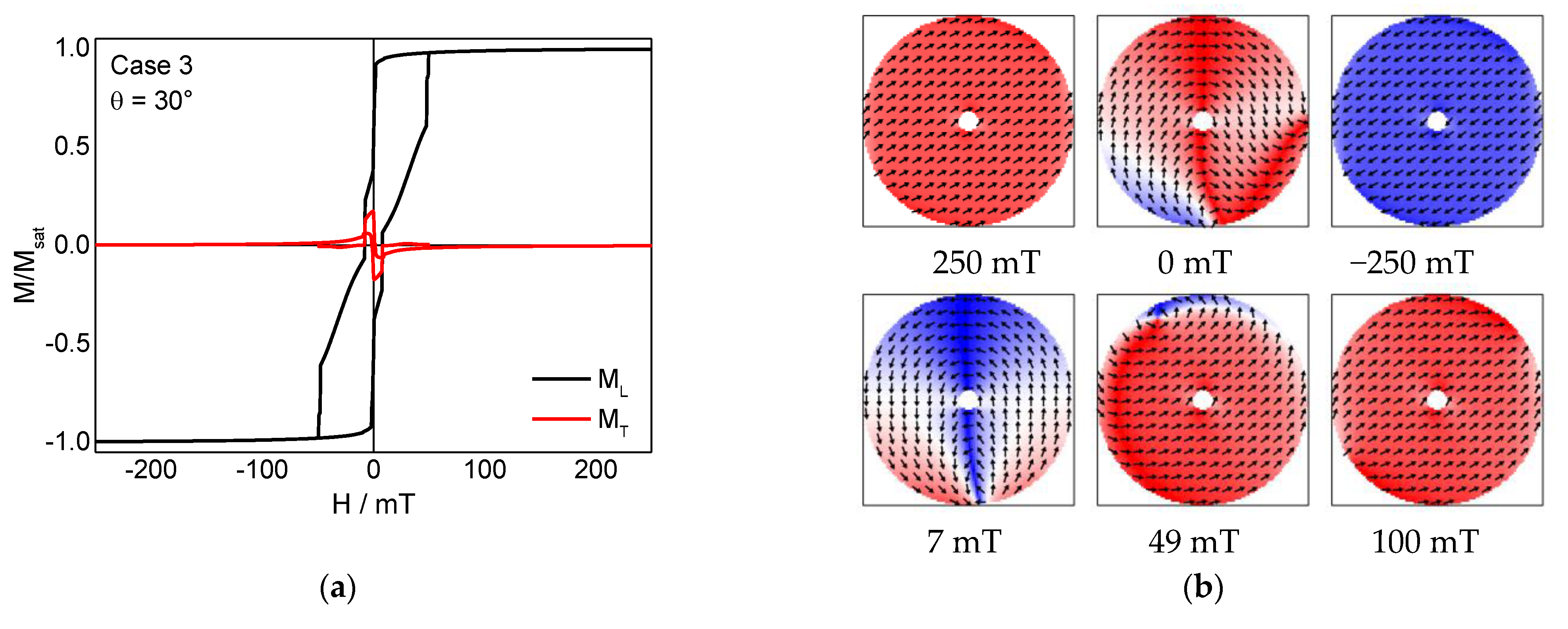
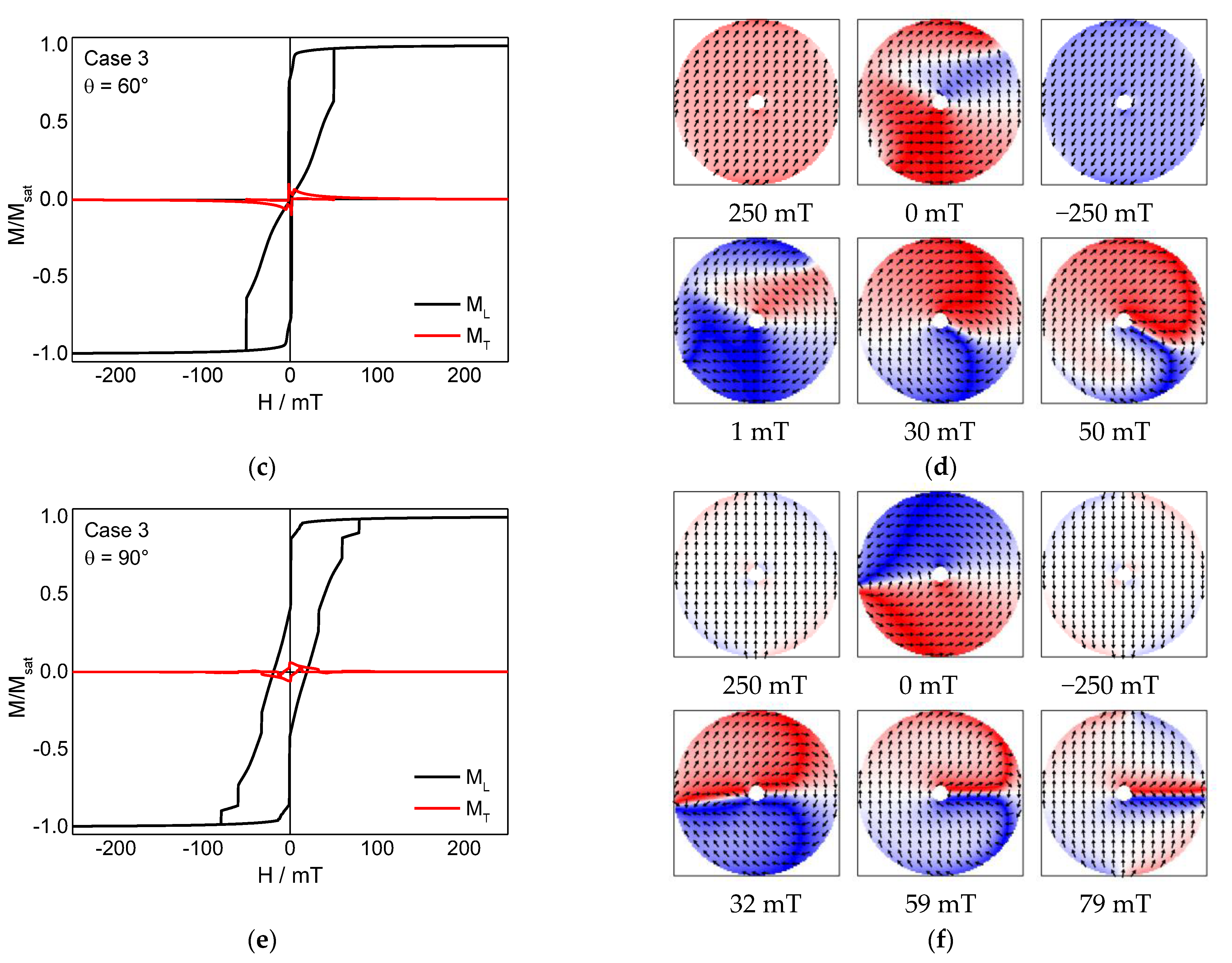
Next, Figure 5 shows simulations of case 3. Here, three qualitatively different types of longitudinal hysteresis loops can be seen. For θ = 30°, we see a longitudinal loop with two steps, at θ = 60° there is one step, and at θ = 90° there are three steps. The differences in the transverse magnetization loops are less easily visible.
Correspondingly, different magnetic states can be found during magnetization reversal. For a field orientation of θ = 30°, the narrow step near 0 mT is correlated with a horseshoe-like state, as depicted in Figure 5b (7 mT). The subsequent broad step is formed by a slightly asymmetric vortex state (49 mT), as it is also visible for θ = 60° (Figure 5d, 30 mT). For θ = 60°, there is no horseshoe state before the vortex state. The simulation of θ = 90° reveals a different magnetization reversal process. Starting again from the horseshoe-like state (Figure 5f, 32 mT), the domain wall of this state vanishes in the next state, while a new domain wall is formed on the opposite side (Figure 5f, 59 mT). At first glance, this second state looks like another horseshoe state; however, a more detailed investigation of the corresponding snapshot reveals a twisted domain wall, i.e., a full rotation of the magnetization between top and bottom of the nanoparticle (depicted in more detail later). This new domain wall is slightly modified in the third step (79 mT) where the magnetic moments along the right edge change their direction.
It must be mentioned that these different magnetization reversal processes, found for different angles, cannot be attributed only to the edge roughness since equivalent angles —θ = 0° and θ = 90°, θ = 30° and θ = 60°, etc.—do not always show the same magnetization reversal processes, as visible by comparing Figure 5a,c. Thus, an additional impact of the randomly chosen anisotropy axis in each grain must be taken into account.
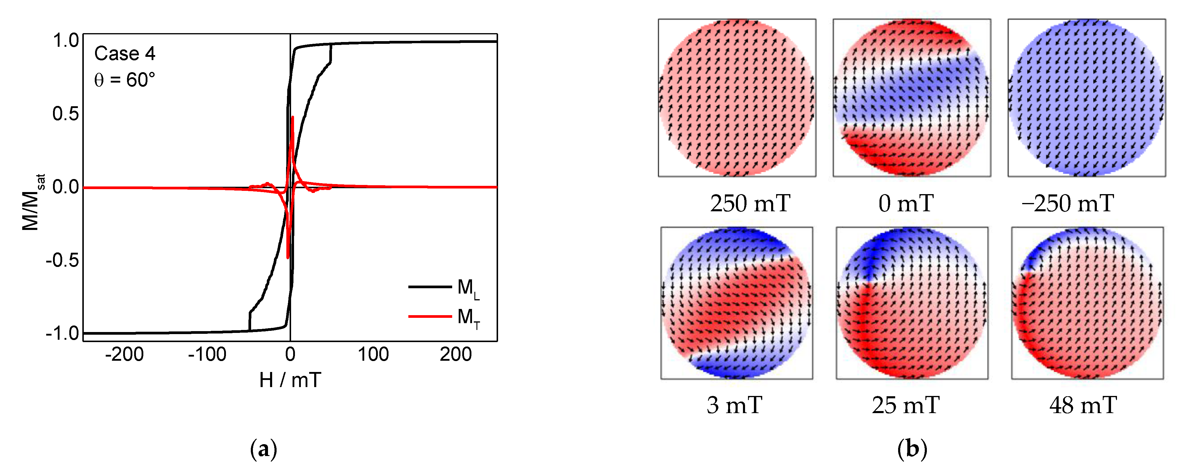
For case 4, magnetization reversal always occurs via a vortex state (Figure 6), which is consistent with a previous examination of this system at θ = 0° [20]. Measuring at an angle different from θ = 0° apparently stabilizes a meander state before the vortex state, as depicted in Figure 6b (3 mT). For θ = 0°, this state was found to occur sometimes in nanodots of similar height and diameter as investigated here, but not reliably [20].
Finally, the results of some simulations of the asymmetric case 5 are depicted in Figure 7. Here, the longitudinal curves are all qualitatively similar, showing two or three steps. Between θ = 60° and θ = 90°, an additional long, flat step is visible (Figure 7e). The transverse magnetization component is relatively large outside the angular range of θ = 30–45°, indicating that the asymmetric hole impedes smooth switching of the magnetization, which is also reflected by the relatively large coercive fields, as compared to the other cases.
For all angles under examination, a vortex state occurs at vanishing external magnetic field (Figure 7b,d, 0 mT), while for angles θ ≥ 45°, a 360° domain wall is visible at the thinnest place (small red area in Figure 7f, 0 mT; depicted in more detail in Figure 8). Afterwards, a domain wall is formed between outer and inner edge (for example, Figure 7b, 36 mT). Besides these magnetic states, different others can occur within small field ranges, such as tail-to-tail and head-to-head domain walls (Figure 7f, −8 mT and 179 mT, respectively) or meander states, combined with different types of domain walls (for example, Figure 7b,d, 36 mT, or Figure 7f, 59 mT). As expected, in this asymmetric nanodot, the geometrical asymmetry clearly dominates any roughness-related effects.
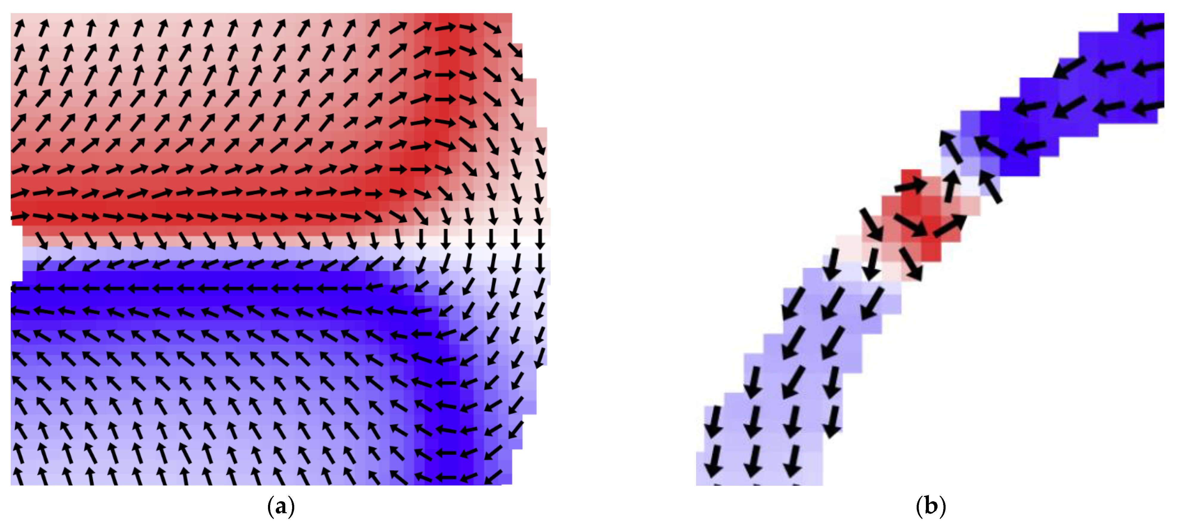
Finally, Figure 8 shows in more detail two special snapshots with small details, corresponding to the twisted domain wall in Figure 5f at 59 mT and to the 360° domain wall at the thinnest position of the asymmetric sample in Figure 7f at 0 mT.

4. Conclusions

Micromagnetic simulations of diverse nanodots with symmetric or asymmetric holes and a defined edge roughness, given by the edge length of 5 nm of the cubes building the nanodots, were performed using OOMMF. While the strongest variations of the transverse magnetization component with the external magnetic field orientation was found in the only particle with an asymmetric hole, and the filled nanodot did not show significant differences between different field orientations, unexpected large deviations were found for three symmetric rings.
These differences partly resulted from arbitrary orientations of the magneto-crystalline anisotropy axes in the single cubes (cases 2 and 3), but especially for the thinnest ring, a clear fourfold anisotropy was introduced by the edge roughness, as visible from the angle-dependent transverse magnetization at remanence. Tests with different cell sizes and different roughness revealed that this effect is due to the roughness and nearly independent from the chosen cell size.
Our findings show that even small geometrical deviations from a perfectly symmetric shape can introduce new—and often unexpected—asymmetries. This can not only be a disadvantage, making measurements of such samples unreliable, but can also be used to support a desired magnetization reversal mechanism without large changes of the sample shape.

Supplementary Materials

The following are available online at https://www.mdpi.com/article/10.3390/condmat6020019/s1, hysteresis loops and exemplary snapshots for all cases and angles under investigation.

Author Contributions

Conceptualization, P.S. and A.E.; validation, P.S. and A.E.; investigation, P.S.; writing—original draft preparation, A.E. and P.S.; writing—review and editing, P.S. and A.E.; visualization, P.S. and A.E. Both authors have read and agreed to the published version of the manuscript.

Funding

This research received no external funding.

Data Availability Statement

All data produced during this study are available in the Supplementary Information.

Conflicts of Interest

The authors declare no conflict of interest.

References

  1. Wachowiak, A.; Wiebe, J.; Bode, M.; Pietzsch, O.; Morgenstern, M.; Wiesendanger, R. Direct observation of internal spin structure of magnetic vortex cores. Science 2002, 298, 577–580. [Google Scholar] [CrossRef]
  2. Guslienko, K.Y.; Aranda, G.R.; Gonzalez, J.M. Topological gauge field in nanomagnets: Spin-wave excitations over a slowly moving magnetization background. Phys. Rev. B 2010, 81, 014414. [Google Scholar] [CrossRef] [Green Version]
  3. Mejía-López, J.; Altbir, D.; Romero, A.H.; Batlle, X.; Roshchin, I.V.; Li, C.-P.; Ivan, S.K. Vortex state and effect of anisotropy in sub-100-nm magnetic nanodots. J. Appl. Phys. 2006, 100, 104319. [Google Scholar] [CrossRef] [Green Version]
  4. Noske, M.; Stoll, H.; Fähnle, M.; Gangwar, A.; Woltersdorf, G.; Slavin, A.; Weigand, M.; Dieterle, G.; Förster, J.; Back, C.H.; et al. Three-dimensional character of the magnetization dynamics in magnetic vortex structures: Hybridization of flexure gyromodes with spin waves. Phys. Rev. Lett. 2016, 117, 037208. [Google Scholar] [CrossRef] [PubMed] [Green Version]
  5. Weigand, M.; van Waeyenberge, B.; Vansteenkiste, A.; Curcic, M.; Sackmann, V.; Stoll, H.; Tyliszczak, T.; Kaznatcheev, K.; Bertwistle, D.; Woltersdorf, G.; et al. Vortex core switching by coherent excitation with single in-plane magnetic field pulses. Phys. Rev. Lett. 2009, 102, 077201. [Google Scholar] [CrossRef] [PubMed] [Green Version]
  6. Gaididei, Y.; Kravchuk, V.P.; Sheka, D.D.; Mertens, F.G. Multiple vortex-antivortex pair generation in magnetic nanodots. Phys. Rev. B 2010, 81, 094431. [Google Scholar] [CrossRef] [Green Version]
  7. Otxoa, R.M.; Petit-Watelot, S.; Manfrini, M.; Radu, I.P.; Thean, A.; Kim, J.-V.; Devolder, T. Dynamic influence of vortex-antivortex pairs in magnetic vortex oscillators. J. Magn. Magn. Mater. 2015, 394, 292–298. [Google Scholar] [CrossRef] [Green Version]
  8. Ehrmann, A.; Blachowicz, T. Influence of tilted fields on magnetization reversal in Fe nanodots. In Proceedings of the IEEE 8th International Conference on Nanomaterials: Applications & Properties, Sumy, Ukraine, 9–11 November 2020. [Google Scholar]
  9. Li, J.Q.; Wang, Y.; Cao, J.F.; Meng, X.G.; Zhu, F.Y.; Tai, R.Z. Fast control of the polarity of the magnetic vortex for a pair of magnetic nanodots. J. Magn. Magn. Mater. 2021, 529, 167841. [Google Scholar] [CrossRef]
  10. Buess, M.; Knowles, T.P.J.; Höllinger, R.; Haug, T.; Krey, U.; Weiss, D.; Pescia, D.; Scheinfein, M.R.; Back, C.H. Excitations with negative dispersion in a spin vortex. Phys. Rev. B 2005, 71, 104415. [Google Scholar] [CrossRef] [Green Version]
  11. Blachowicz, T.; Ehrmann, A.; Steblinski, P.; Palka, J. Directional-dependent coercivities and magnetization reversal mechanisms in fourfold ferromagnetic systems of varying sizes. J. Appl. Phys. 2013, 113, 013901. [Google Scholar] [CrossRef] [Green Version]
  12. Janutka, A.; Gawronski, P. Spin-transfer-driven dynamics of magnetic vortices and antivortices in dots with crystalline cubic anisotropy. IEEE Trans. Magn. 2017, 53, 4300706. [Google Scholar] [CrossRef]
  13. Pylypovskyi, O.V.; Sheka, D.D.; Kravchuk, V.P.; Gaididei, Y. Effects of surface anisotropy on magnetic vortex core. J. Magn. Magn. Mater. 2014, 361, 201–205. [Google Scholar] [CrossRef] [Green Version]
  14. Sudsom, D.; Ehrmann, A. Micromagnetic simulations of Fe and Ni nanodot arrays surrounded by magnetic or non-magnetic matrices. Nanomater. 2021, 11, 349. [Google Scholar] [CrossRef]
  15. Sudsom, D.; Juhász Junger, I.; Döpke, C.; Blachowicz, T.; Hahn, L.; Ehrmann, A. Micromagnetic simulation of vortex development in magnetic bi-material bow-tie structures. Condens. Matter 2020, 5, 5. [Google Scholar] [CrossRef] [Green Version]
  16. Sellarajan, B.; Saravanan, P.; Ghosh, S.K.; Nagaraja, H.S.; Barshilia, H.C.; Chowdhury, P. Shape induced magnetic vortex state in hexagonal ordered CoFe nanodot arrays using ultrathin alumina shadow mask. J. Magn. Magn. Mater. 2018, 451, 51–56. [Google Scholar] [CrossRef]
  17. Prejbeanu, I.L.; Natali, M.; Buda, L.D.; Ebels, U.; Lebib, A.; Chen, Y.; Ounadjela, K. In-plane reversal mechanism in circular Co dots. J. Appl. Phys. 2002, 91, 7343–7345. [Google Scholar] [CrossRef]
  18. Vavassori, P.; Zaluzec, N.; Metlushko, V.; Novosad, V.; Ilic, B.; Grimsditch, M. Magnetization reversal via single and bouble vortex states in submicron Permalloy ellipses. Phys. Rev. B 2004, 69, 214404. [Google Scholar] [CrossRef] [Green Version]
  19. Prosandeev, S.; Bellaiche, L. Controlling double vortex states in low-dimensional dipolar systems. Phys. Rev. Lett. 2008, 101, 097203. [Google Scholar] [CrossRef] [Green Version]
  20. Ehrmann, A.; Blachowicz, T. Vortex and double-vortex nucleation during magnetization reversal in Fe nanodots of different dimensions. J. Magn. Magn. Mater. 2019, 475, 727–733. [Google Scholar] [CrossRef]
  21. Zhang, W.; Haas, S. Phase Diagram of Magnetization Reversal Processes in Nanorings. Phys. Rev. B 2010, 81, 064433. [Google Scholar] [CrossRef] [Green Version]
  22. Yoo, Y.G.; Kläui, M.; Vaz, C.A.F.; Heyderman, L.J.; Bland, J.A.C. Switching field phase diagram of Co nanoring magnets. Appl. Phys. Lett. 2003, 82, 2470–2472. [Google Scholar] [CrossRef]
  23. Vaz, C.A.F.; Hayward, T.J.; Llandro, J.; Schackert, F.; Morecroft, D.; Bland, J.A.C.; Kläui, M.; Laufenberg, M.; Backes, D.; Rüdiger, U.; et al. Ferromagnetic nanorings. J. Phys. Condens. Matter 2007, 19, 255207. [Google Scholar] [CrossRef] [Green Version]
  24. Park, M.H.; Hong, Y.K.; Choi, B.C.; Donahue, M.J.; Han, H.; Gee, S.H. Vortex head-to-head domain walls and their formation in onion-state ring elements. Phys. Rev. B 2006, 73, 094424. [Google Scholar] [CrossRef] [Green Version]
  25. Muscas, G.; Menniti, M.; Brucas, R.; Jönsson, P.E. Mesoscale Magnetic Rings: Complex magnetization reversal uncovered by FORC. J. Magn. Magn. Mater. 2020, 502, 166559. [Google Scholar] [CrossRef]
  26. Fernandez, E.; Tu, K.-H.; Ho, P.; Ross, C.A. Thermal stability of L10-FePt nanodots patterned by self-assembled block copolymer lithography. Nanotechnology 2018, 29, 465301. [Google Scholar] [CrossRef] [Green Version]
  27. Bryan, M.T.; Atkinson, D.; Cowburn, R.P. Experimental study of the influence of edge roughness on magnetization switching in Permalloy nanostructures. Appl. Phys. Lett. 2004, 85, 3510. [Google Scholar] [CrossRef]
  28. Zhu, F.Q.; Shang, Z.; Monet, D.; Chien, C.L. Large enhancement of coercivity of magnetic Co/Pt nanodots with perpendicular anisotropy. J. Appl. Phys. 2007, 101, 09J101. [Google Scholar] [CrossRef]
  29. Li, X.; Leung, C.W.; Chiu, C.-C.; Lin, K.-W.; Chan, M.S.; Zhou, Y.; Pong, P.W.T. Reduced magnetic coercivity and switching field in NiFeCuMo/Ru/NiFeCuMo synthetic-ferrimagnetic nanodots. Appl. Surf. Sci. 2017, 410, 479–484. [Google Scholar] [CrossRef]
  30. Madami, M.; Gubbiotti, G.; Tacchi, S.; Carlotti, G. Magnetization dynamics of single-domain nanodots and minimum energy dissipation during either irreversible or reversible switching. J. Phys. D. Appl. Phys. 2017, 50, 453002. [Google Scholar] [CrossRef]
  31. Tu, K.-H.; Bai, W.B.; Liontos, G.; Ntetsikas, K.; Avgeropoulos, A.; Ross, C.A. Universal pattern transfer methods for metal nanostructures by block copolymer lithography. Nanotechnology 2015, 26, 375301. [Google Scholar] [CrossRef] [Green Version]
  32. Donahue, M.J.; Porter, D.G. OOMMF User’s Guide; Version 1.0; Interagency Report NISTIR 6376; National Institute of Standards and Technology: Gaithersburg, MD, USA, 1999. [Google Scholar]
  33. Gilbert, T.L. A phenomenological theory of damping in ferromagnetic materials. IEEE Trans. Magn. 2004, 40, 3443–3449. [Google Scholar] [CrossRef]
  34. Leliaert, J.; Dvornik, M.; Mulkers, J.; de Clercq, J.; Milosevic, M.V.; van Waeyenberge, B. Fast micromagnetic simulations on GPU – recent advances made with mumax3. J. Phys. D Appl. Phys. 2018, 51, 123002. [Google Scholar] [CrossRef]
  35. Kneller, E.F.; Hawig, R. The exchange-spring magnet: A new material principle for permanent magnets. IEEE Trans. Magn. 1991, 27, 3588–3560. [Google Scholar] [CrossRef]
  36. Ehrmann, A.; Blachowicz, T. Asymmetric hysteresis loops in Co thin films. Condens. Matter. 2020, 5, 71. [Google Scholar] [CrossRef]
Figure 1. Sketches of the five cases under examination: (a) case 1; (b) case 2; (c) case 3; (d) case 4; and (e) case 5; (f) definition of angles in this study. The colour of the snapshots depends on the orientation of the magnetization: red = magnetization pointing to the right, blue = magnetization pointing to the left, white = magnetization pointing from top to bottom or vice versa.
Condensedmatter 06 00019 g001
Figure 2. (a,c,e) Hysteresis loops and (b,d,f) snapshots of the magnetization reversal from positive to negative saturation and back for case 1, simulated for the angles θ depicted in the graphs.
Condensedmatter 06 00019 g002aCondensedmatter 06 00019 g002b
Figure 3. (a) Hysteresis loops, simulated for case 1 at θ = 0° with different random orientations of anisotropy axes and different edge definitions; (b) comparison between different cells sizes and edge constructions; (c) comparison between different simulation ΔH; (d) snapshots for the magnetization reversal with “smoothed” edges.
Condensedmatter 06 00019 g003aCondensedmatter 06 00019 g003b
Figure 4. (a,c) Hysteresis loops and (b,d) snapshots of the magnetization reversal from positive to negative saturation and back for case 2, simulated for the angles depicted in the graphs.
Condensedmatter 06 00019 g004
Figure 5. (a,c,e) Hysteresis loops and (b,d,f) snapshots of the magnetization reversal from positive to negative saturation and back for case 3, simulated for the angles depicted in the graphs.
Condensedmatter 06 00019 g005aCondensedmatter 06 00019 g005b
Figure 6. (a) Hysteresis loop and (b) snapshots of the magnetization reversal from positive to negative saturation and back for case 4, simulated for θ = 60°.
Condensedmatter 06 00019 g006
Figure 7. (a,c,e) Hysteresis loops and (b,d,f) snapshots of the magnetization reversal from positive to negative saturation and back for case 5, simulated for the angles depicted in the graphs.
Condensedmatter 06 00019 g007aCondensedmatter 06 00019 g007b
Figure 8. Snapshots of the magnetization, taken of (a) the twisted domain wall in Figure 5f at 59 mT; (b) the 360° domain wall at the thinnest position in Figure 7f at 0 mT.
Condensedmatter 06 00019 g008
Publisher’s Note: MDPI stays neutral with regard to jurisdictional claims in published maps and institutional affiliations.