Review

Fabry-Perot Cavity Leaky Wave Antennas with Tunable Features for Terahertz Applications

Department of Information Engineering, Electronics and Telecommunications, “Sapienza” University of Rome, via Eudossiana 18, 00184 Rome, Italy
*
Author to whom correspondence should be addressed.
Condens. Matter 2020, 5(1), 11; https://doi.org/10.3390/condmat5010011
Submission received: 13 January 2020 / Accepted: 22 January 2020 / Published: 25 January 2020

Abstract

:
Terahertz (THz) radiation is a very appealing band of the electromagnetic spectrum due to its practical applications. In this context, the THz generation and manipulation is an essential part of the technological development. The demand of THz antennas is still high because it is already difficult to obtain directive, efficient, planar, low-cost, and easy-to-fabricate THz radiating systems. In this regard, Fabry-Perot cavity leaky-wave antennas are gaining increasing attention at THz, due to their very interesting radiating features: the combination of planar designs with metamaterials and metasurfaces could offer a promising platform for future THz manipulation technologies. In this short review, we focus on different classes of leaky-wave antennas, based on materials with tunable quasi-optical parameters. The possibility of producing directive patterns with particularly good efficiencies, as well as the capability of dynamically reconfiguring their radiating features, are discussed by taking into account the risk of increasing costs and fabrication complexity.

1. Introduction

The terahertz (THz) band conventionally occupies the region of the electromagnetic spectrum between the high-frequency limit of the microwaves, often indicated as 300 GHz, and the low-frequency edge of the infrared frequency range, usually fixed at 10 THz. This corresponds to wavelengths in the range between 300 μm to 1 mm. Historically, THz detection was conceived for interstellar dust sensing between 100 GHz and 3 THz. Nowadays, several applications have been exploited, such as molecular spectroscopy and high-resolution imaging [1], non-destructive testing [2], security screening [3], explosives and drug detection [4], monitoring of water content in human tissues [5], and high data-rate communications [6,7]. Moreover, THz communications are gaining an increasing interest, connected to the possibility to have access to Tbps wireless links [8]. In this context, there is a request to develop antennas, which (i) could be fabricated with low-cost materials, (ii) are light and simple to integrate, and (iii) may exhibit reconfigurable properties.
Among the class of planar antennas, leaky-wave antennas (LWAs) are promising devices at THz frequencies. LWAs are travelling-wave antennas and they are well-known radiating systems at microwaves from decades. In LWAs, radiation phenomena are interpreted as an energy leakage of a wave that propagates in a partially open structure. The wave propagating in a LWA progressively loses its energy due to both the (undesirable) losses in the medium and the radiation losses [9]. Because of such energy outflow, leaky waves are described by a generally complex propagation wavenumber.
The main advantages of LWAs are the simple fabrication and design as well as the ubiquity of leaky-wave phenomena from microwaves (i.e., the historical starting point of the leaky-wave theory), to nano-optics (thanks to the current developments in metasurfaces and nanostructured materials). For this reason, they are perfectly suitable for being scaled at THz frequencies.
This review aims to analyze and describe the design of novel reconfigurable Fabry-Perot cavity leaky-wave antennas (FPC-LWAs) layouts for THz applications, focusing on the fabrication constraints that could have an impact on the FPC-LWA layout in the THz range. After introducing in Section 2 the theoretical background of the leaky waves and the leaky-wave antennas, in Section 3 and Section 4, we focus on two complementary approaches for the design of tunable THz FPC-LWAs by means of an electro-optical control. In Section 5, we present and discuss the strategies for a wide reconfigurability of the THz radiation pattern by means of two-dimensional (2D) materials with tunable quasi-optical parameters. Conclusions are drawn in Section 6.

2. Leaky-Wave Antennas

LWAs are travelling wave antennas in which the propagating modes responsible for the radiation (i.e., the leaky waves) are characterized by a generally complex propagation wavenumber kz = βzz, where βz is the phase constant and αz is the attenuation constant. Moreover, in order to effectively radiate [10,11], the leaky wave propagating in the structure has to be a fast wave, i.e., characterized by |βz| < k0 where k0 is the free-space wavenumber. Therefore, the operation of a LWA is quite different from a slow-wave or a surface-wave type of antenna, for which radiation mainly takes place at discontinuities (e.g., at the edge of the structure) [12]. In the absence of ohmic losses, αz takes into account only power losses due to radiation and it is called “leakage constant”: it represents the rate of decreasing of the aperture field due to the leakage mechanism of radiation.
LWAs can be divided into several categories, according to their geometrical structure and their principle of operation [13]. A rigorous description goes beyond the aim of this work and can be found in [14]. A first distinction can be made between one-dimensional (1D) and two-dimensional (2D) LWAs, that differ from each other for the nature of the leaky waves propagating in the structure. In the former case, leaky waves propagate along a longitudinal direction with a planar wavefront; in the latter case, leaky waves radially propagate with a cylindrical wavefront. This important distinction considerably affects the radiation features: a 1D LWA usually produces fan beams, while a 2D LWA mainly radiates pencil beams or fully conical beams.
Then, LWAs can also be divided, according to their structure, in uniform, quasi-uniform and periodic antennas. This distinction can affect the antenna scanning characteristics. In fact, a uniform LWA usually scans inside the forward spatial quadrant by varying the operating frequency, while a periodic LWA can scan the radiation beam in both forward and backward quadrants. However, some exceptions could exist.

2.1. Fabry-Perot Cavity Leaky-Wave Antennas

FPC-LWAs as those discussed here are 2D quasi-uniform LWAs and can be considered as partially-open and partially-guiding structures that support the radial propagation of cylindrical leaky waves [15]. The working principle of these structures is based on the occurrence of a gain-enhancement and was originally formulated, according to a ray-optics modeling, as a phenomenon of multiple beam interference [16]. However, the radiation properties of the FPC-LWAs can also be addressed under the frame of leaky-wave theory [13].
An FPC is able to radiate when the fundamental leaky modes supported by the cavity are excited by the antenna feed. Interestingly, if a horizontal electric or magnetic dipole is selected as excitation for the FPC-LWA, the antenna radiates a directive pencil beam at broadside at its frequency of operation.
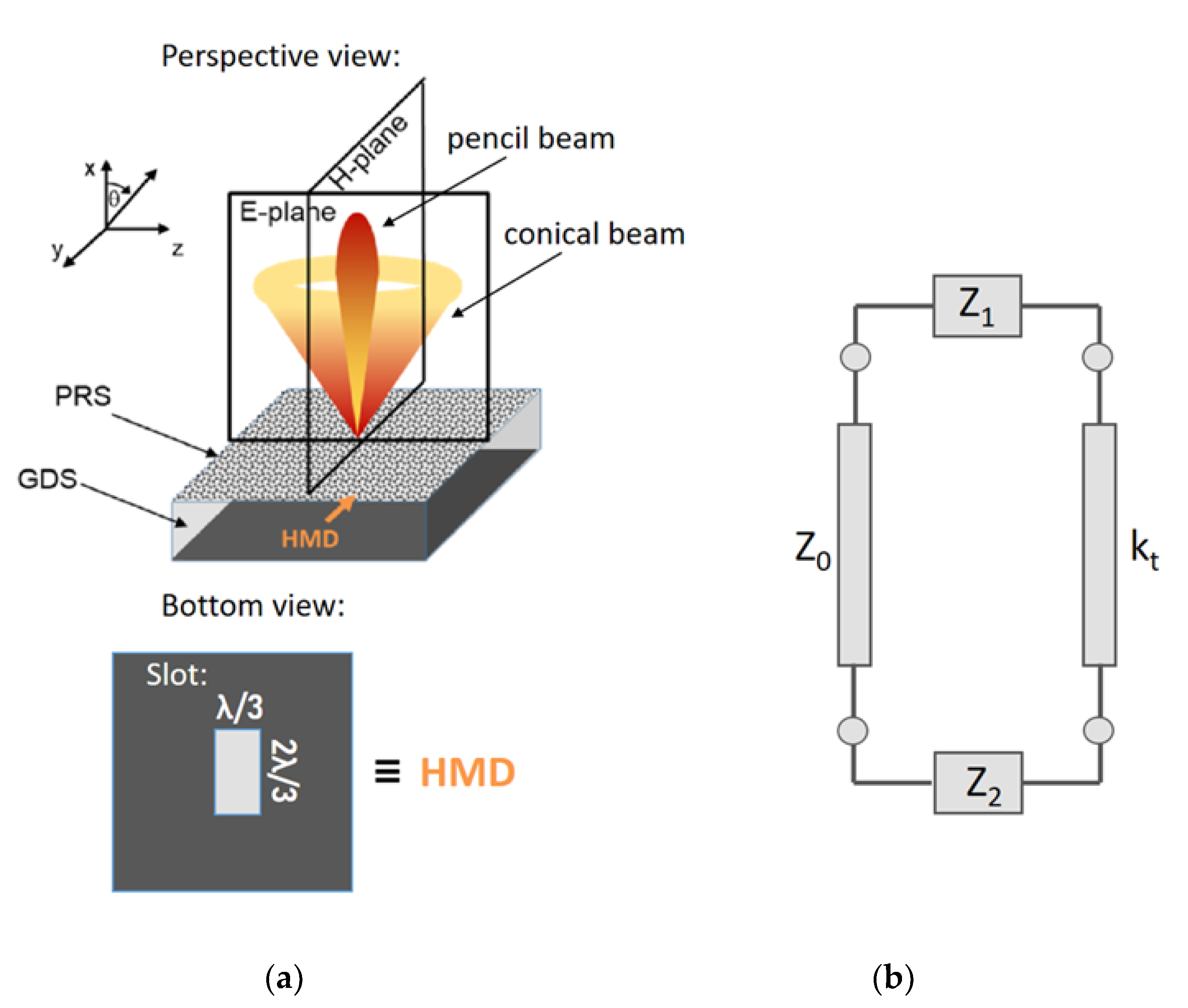
For frequencies close to the operating frequency, an FPC-LWA emits a conical beam that has the cone axis along the vertical x-axis (see Figure 1a) [13,17,18].
An FPC-LWA layout consists of a grounded dielectric slab (GDS) covered with a partially reflecting sheet (PRS) [19]. The PRS can assume several shapes, e.g., a distributed Bragg reflector, a simple dielectric layer with a refractive index higher than the substrate, or a metasurface. In any case, the antenna design process is the same, thanks to the leaky-wave approach.

2.2. Antenna Parameters and Main Rules for FPC-LWA Design

The radiation properties of an FPC-LWA depend on the source type. FPC-LWAs for THz radiation are usually fed by a horizontal magnetic dipole (HMD) because, differently from a vertical dipole, it allows for emitting THz radiation in the broadside direction. An HMD is able to excite the pair of fundamental TE and TM leaky modes, both characterized by a complex propagation wavenumber, as already discussed in Section 1.
The setting of a proper design of the FPC-LWAs, i.e., a design in which some assumptions are satisfied [17], is important for describing radiation as caused only by the fundamental leaky modes. When these two conditions are met (i.e., an HDM is selected as a feed and the FPC-LWA is designed according to the design rules in [20]), the TM leaky mode affects radiation in the antenna E-plane, while the TE leaky mode is responsible for the radiation pattern in the antenna H-plane. In the condition of broadside radiation, nearly the same attenuation and phase constant values characterize the TE and TM leaky modes: the FPC-LWA radiates an omnidirectional pencil beam.
The pointing angles θ 0 TE and θ 0 TM of the beam are measured from the vertical axis (x-axis of Figure 1) and their expression is [20].
θ 0 TE , TM arcsin ( β z TE , TM k 0 ) 2 ( α z TE , TM k 0 ) 2
Equation (1) also defines two regimes of radiation: if β z α z , the FPC-LWA emits radiation at broadside; if β z α z , the FPC-LWA emits a conical beam. When β z α z , the radiation emitted at broadside reaches its maximum value. Such condition is usually set as the operative one and it is the starting point in the FPC-LWA design process. The antenna beamwidth in the E- and H-plane is [15].
{ Δ θ TE = 2 α z TE k 0 sec θ 0 TE   ,   Δ θ TM = 2 α z TM k 0 sec θ 0 TM     for   β z α z Δ θ TE = 2 2 α z TE k 0 ,   Δ θ TM = 2 2 α z TM k 0   for   β z α z
It is important to point out that the beamwidths and the pointing angles are different on the E- and H-planes when the wavenumber of the TM and TE mode differs, i.e., when the scanning angle increases. For this reason, in several applications in which the pointing angle changes, it could be important to select an antenna PRS that shows the same behavior for both TM and TE polarizations. In this way, the antenna is able to emit an almost circular conical beam when β z α z .
In the leaky-wave theory [13], a leaky-wave antenna is interpreted as a radiating version of a parallel plate waveguide (PPW), due to the presence of a PRS that allows a radiation leakage. In fact, a grounded dielectric slab covered by a PRS (instead of a reflecting surface) supports a pair of fundamental TE-TM leaky modes (instead of the fundamental TE-TM PPW guided modes), that can eventually radiate if properly excited. Two key geometrical parameters in the design of a FPC-LWA [17] are the lateral size of the antenna (i.e., with respect to the axis reported in Figure 1a, the antenna dimensions along the y- and z-axis) and the substrate thickness. The antenna efficiency, i.e., the ratio between the radiated and the incoming power, is related to the lateral size of an FPC-LWA. In order to avoid pattern deterioration due to diffraction effects from edges, the lateral size of the antenna (i.e., lateral truncation) should be set so as the travelling cylindrical modes have radiated at least 90% of the input power before they reach the lateral truncation [21].
Under the condition of broadside radiation and of antenna of infinite lateral extent (i.e., radiation efficiency ≥90% by design), for the TE and TM fundamental leaky modes, the thickness of the antenna substrate is given by a simple formula [15].
h = λ 0 / ( 2 n s )
where n s is the antenna substrate refractive index at the design frequency, i.e., the frequency at which β z α z .

2.3. Techniques for the Analysis of FPC-LWA Features

Two standard methods are usually employed for the analysis of complex structures: the mode matching technique [22] and the transverse resonance technique [23]. The mode matching technique is a time-consuming technique, especially if the domain of interest is composed by more than one medium. In the situation in which only the determination of the eigenvalues is of interest, the transverse resonance technique represents an appropriate tool [23]. In fact, the eigenvalues of a waveguide problem correspond to pole singularities of a suitable characteristic Green’s function in the complex plane of the propagation wavenumber. This Green’s function can be identified as the voltage (or current) on a transmission line along one of the transverse direction of the waveguide axial direction [24,25]. The pole singularities correspond to the transverse equivalent network (TEN) model resonances and are usually computed using analytical methods.
A general form of terminated TEN is given in Figure 1b. The transverse wavenumber kt that corresponds to source-free fields in the waveguide can be derived from the solution of the resonance equation:
Z ( k t ) = Z ( k t ) + Z ( k t )   or   Y ( k t ) = Y ( k t ) + Y ( k t )
where Z , Y , Z , and Y are the impedances or admittances from the left and the right of an arbitrary reference plane. A closed-form analytical solution to this resonance equation does not generally exist, except for very simple canonical examples, such as the parallel-plate waveguide [23,26].
In the simple situation in which the leaky wave can be seen as a perturbation of a mode in a closed waveguide [25], the transverse wavenumber can be considered as:
k t = k t 0 + Δ k t
where k t 0 is the wavenumber of the unperturbed mode and Δ k t is the perturbation. If the cross-section is homogeneous, the resonance equation can be written in terms of normalized impedances (admittances), expanded in the point k t = k t 0 :
Z ( k t 0 ) + ( d Z ( k t ) d k t ) k t = k t 0 Δ k t 0
Δ k t Z ( k t 0 ) ( d Z ( k t ) d k t ) k t = k t 0   or   Δ k t Y ( k t 0 ) ( d Y ( k t ) d k t ) k t = k t 0
where Z = Z / Z 0 is the normalized impedance, and Y = Y / Y 0 is the normalized admittance.

2.4. Fabry-Perot Cavity Leaky Wave Antennas at THz Frequencies

Leaky-wave phenomena occur at any frequency range. For this reason, LWAs working at THz frequencies are feasible and some examples of devices are already present in the scientific literature [15,27,28,29,30,31,32,33,34,35,36,37,38,39,40,41,42,43,44]. In this section, only LWAs working in the frequency band between 300 GHz and 3 THz are discussed. The choice of this specific frequency band is linked to a technological challenge that characterizes the so-called “terahertz gap” [45]. In fact, even if the border between millimeters waves and far-IR has not been delimited yet, below 0.3 THz, facilities developed for the millimeter waves are available, while, above 3 THz, the mechanisms connected to the description of far-IR radiation are predominant.
The most studied THz LWA is a leaky waveguide coupled with a hemispherical silicon lens. It is able to operate at a fixed value of frequency [27,28] or in a frequency band of 0.2 THz [29] until 1.4 THz [30,31,32] wide. When the device works at a single frequency, it can show a very high directivity (i.e., the power density emitted by the antenna versus the power density emitted by an ideal isotropic radiator, when they radiate the same total power); for example [27], of 42.1 dB. Lens-like LWAs able to operate in a frequency band wider than 1 THz can be employed for practical applications, such as THz detectors. However, independently from the operating frequencies of the antenna, the radiation efficiency is always below 75%, due to losses introduced by the coupling with a silicon lens.
With respect to FPC-LWAs, the maximum radiated power at broadside is connected to the resonance condition of the multiple reflections. For this reason, FPC-LWAs usually work around a narrow band centered at the resonance frequency of the FPC. The PRS can assume several forms. In [33,34,35], the performances of FPC-LWAs with different metasurface geometries are compared. A metasurface is, in general, a metallic patterned surface, in which the geometrical elements composing the pattern have dimensions deeply below the operative wavelength [46]. It means that this surface can be considered as a homogeneous surface with properties depending on the specific geometrical pattern chosen for the metasurface synthesis. Even if several geometries have been investigated in the THz range as PRS for FPC-LWAs, none of them has been fully characterized yet. However, they show advantages common to many LWAs, such as the suitability to miniaturization and integration on complex devices or the scalability at every THz frequency value of operation. The radiation efficiencies, computed for the structures presented in [33,34,35], do not go beyond the 75%, but the high number of degrees of freedom in the metasurfaces design may allow for higher values. In this context, a fishnet metasurface has been recently introduced as a spatially nondispersive PRS with a design able to synthetize surfaces that allow for directivities ranging from 15 to 30 dB [36,37,38].
An interesting opportunity offered by FPC-LWAs is the possibility to develop THz antennas with a reconfigurable pointing angle at a fixed frequency. The only two ways, currently present in literature in the frequency band of interest, to steer the beam is the use of a graphene sheet as a PRS [39,40,41] or the integration in the LWA layout of one or more liquid crystal (LC) layers [15,42]. An alternative way to steer the beam is to change the operating frequency. An example is presented in [43,44], where a microstrip LWA with periodic elements is investigated as a THz radar and shows a beam steering over an angular range of 38°, with a very narrow radiated beam. However, this kind of device has a limited application as radar to a short range object detection [43].
Other forms of FPC-LWAs working in the THz range will be widely analyzed in the following sections, where FPC-LWA structures implementing strategies for reconfiguring the emitted beam pointing angle will be described in terms of design and numerical investigation.

3. Fabry-Perot Cavity Leaky Wave Antennas Based on Tunable Metamaterials

In this section, we start our analysis about the design possibilities offered by different tunable materials by introducing an FPC-LWA structure made with a GDS covered by a metamaterial. The metamaterials are artificial materials obtained from the combination of different materials, present in nature, with spacing and geometrical features below the wavelength dimension. The metamaterial of Figure 2a consists of a multilayered structure in which layers of material with high refractive index are interleaved with LC layers. Because of both the ordinary and the extraordinary refractive index of the LC has a value lower than the other material constituting the multilayer, the PRS can be considered as a distributed Bragg reflector.

3.1. Liquid Crystals for THz Antenna Design

Liquid crystals are materials that exhibit a solid crystalline phase, a liquid phase and intermediate phases in which they flow like a liquid, but show a preferred orientation. These intermediate phases are called mesophases. It is possible to distinguish several mesophases by changing temperature, concentration, constituents, substituents, or other LCs or environmental properties [47]. Materials constituted by molecules with an anisotropic shape could reveal mesophases. For this reason, it is common to refer to LCs as rod-like molecules [48]. Thermotropic are the most extensively studied LCs. They exhibit different mesophases as temperature increases. When the thermotropic LC is in a nematic phase, its rod molecules have a random position. The nematic phase could remind a liquid; however, LC molecules are aligned in the same direction defined by a unit vector called director.
When an external perturbation field is applied on LCs in nematic phase, they are subjected to deformation, as a solid. However, in a solid, the stress produces a translational displacement of molecules while, in LCs, molecules rotate in direction of the force without any displacement in their centre of gravity. In general, in nematic LCs subjected to an external electric field, the director vector experiments a torque force. LCs respond to this external force with a reorientation of their long axis, which is influenced by several factors.
Thermotropic nematic LC layers are usually employed in a confined geometry, called “cell”, i.e., a cavity in which the top and bottom walls are covered with thin layers of polymeric material, typically a polyimide or polyamide. In free space optics, the edges are usually neglected as these lie outside the useable area of the device. This thin layer undergoes a mechanical [49] or optical [50] process able to align the polymer chains in a same direction (planar homogeneous alignment). When the nematic LC is in contact with this layer, it is energetically favourable that the LC director has the same direction of polymer chains. In this way, the first layer of rods is considered as anchored to the cell walls. The second layer follows the alignment pattern of the first layer, but experiments a lower anchoring, and so on. When LC molecules are strongly anchored to a boundary, surface interactions are not considered in the evaluation of rod molecules motion in nematic LCs due to external field interactions [47].
Moreover, the electronic response of LCs to an external electric field is characterized by its dielectric constants (or refractive indices), as well as electrical conductivities. These physical parameters are dependent on the direction of the external field and to its frequency: the dielectric permittivity is a tensor and its elements are, in general, complex numbers. Rod-like molecules are usually uniaxial LCs and the permittivity tensor is:
ε = = ε 0 [ ε 0 0 0 ε 0 0 0 ε ]
and similarly for the conductivity tensor. In Equation (8), the dielectric permittivity is considered as the product of the vacuum permittivity ε 0 and the extraordinary relative permittivity ε of the LC, when the director is parallel to the applied field, and it is the product of the vacuum permittivity ε 0 and the ordinary relative permittivity ε of the LC, when the director is perpendicular to the applied field. Pure organic LCs are highly purified nonconductive materials (i.e., σ = 0), though they may become conductive by adding ions and impurities. Electrical conductivity influences director orientation, chemical degradation and LC lifetime.
Regarding dielectric permittivity, in most cases, ε > ε due to molecular structure and constituents. This condition is called positive anisotropy, i.e., Δ ε = ( ε ε ) / S eq > 0 , where Seq is the order parameter under equilibrium condition. In general, the elements in dielectric permittivity tensor are frequency dispersive and some LCs could change their anisotropy from negative to positive by increasing external field frequency [47].
When an external electric field E is applied, if its strength is more than a critical value EF, called Freedericksz transition [51], the LC director rotates by an angle θ with respect to its rest position, trying to align itself with the field direction:
E F = π d ( K Δ ε ) 1 2   or   V F =   π ( K Δ ε ) 1 2
where d is the distance between the electrodes which apply the field, and K is a local field factor. K takes into account the Frank elastic constants describing LC director deformation: the splay modulus k11, the twist modulus k22, and the bend modulus k33 [48]. Under the condition of strong anchoring, if the external field induces a reorientation of the director from parallel to perpendicular with respect to electrodes plane:
K = k 11 + 1 4 ( k 33 2 k 22 )
The rod molecules reorientation determines a change in a LC dielectric permittivity as well as in its refractive index. In fact, as discussed above, in the absence of external fields, LC permittivity is expressed by Equation (8). For values of applied voltage higher than the Freedericksz transition, it becomes [47]:
ε = = ε 0   [ ε 0 0 0 ε 0 0 0 ε ]
In the application of Figure 2, we consider the nematic LC mixture 1825 [52,53] due to its high birefringence and moderate losses in the THz frequency range. The selected LC has an ordinary and extraordinary permittivity equal to ε = 2.3 and ε = 2.42 at 1 THz, Frank elastic constants k11 = 12.5 pN, k22 = 7.4 pN, k33 = 32.1 pN, and viscosity γ = 311.55 mPa·s [52,53]. As every uniaxial LC, the 1825 mixture has a permittivity that, for V = 0, can be described by Equation (8) and, for V > VF, is represented by Equation (11). For intermediate state, i.e., for 0 < V < VF, the permittivity tensor is no longer represented by a diagonal matrix. However, if the LC director is aligned along the z-axis, and a low driving voltage is applied, the LC molecules tilt in the xz-plane exhibiting a negligible rotation over both the yz- and the xy-plane [15,42]. With this approximation, the LC can still be locally modelled as a uniaxial crystal. The permittivity tensor can be generically expressed as:
ε r = ( V ) = [ ε x ( V ) 0 0 0 ε y ( V ) 0 0 0 ε z ( V ) ]
where ε = = ε 0 ε r = ( V ) . The assumption of uniaxial LC is important in the design of an FPC-LWA because it allows for modeling the antenna by means of a simple TEN. In the following, we will consider only the two limiting cases V = 0 and V > VF, while the value of the permittivity in the LC layer is considered as a medium value in the selected direction (i.e., it takes into account the local variations due to the anchoring effect).

3.2. Design of the Fabry-Perot Cavity Leaky-Wave Antenna with Liquid Crystals

The innovative elements of the FPC-LWA in Figure 2 are its capability of changing its equivalent impedance by applying an external bias voltage to the LC cells. The change in impedance corresponds to a variation in the FPC-LWA pointing angle at the operative frequency. The FPC-LWA’s multilayer is a stack of alumina layers ( ε r , A l = 9 ,   tan δ = 0.01 , at 1 THz) and LC cells. The multilayer is placed over a GDS made with Zeonex E48R ( ε r , Z e = 2.3 ,   tan δ = 0.006 , at 1 THz, Zeon Corporation, Tokyo, Japan), a cyclic olefin copolymer with a permittivity matched with the ordinary permittivity of the selected LC mixture. In this way, it is possible to enhance the resonance condition of the FPC [54]. The thickness of the layers in the stack is fixed at odd multiples of a quarter wavelength in the corresponding media. This choice guarantees that the FPC-LWA is able to radiate a narrow beam at broadside, i.e., the antenna is highly directive at broadside.
The equivalent circuit model of the multilayer FPC-LWA with LCs is reported in Figure 2b. The TEN takes into account the LC anisotropy and is the starting point of the dispersion analysis. When no voltage is applied to the LC layers, the LC molecules are oriented along the z-axis and ε z ( V = 0 ) = ε (compare Equation (8)). When a voltage V > VF is applied to the LCs, the rod-like molecules reorient their principal axis parallel to the external E-field and ε x ( V > V F ) = ε (compare Equation (11)). With regard to the transverse transmission line model (Figure 2b), the characteristic admittances, Y3, and the normal wavenumbers, kx3, of the LC layers for both transverse-electric (TE) and transverse-magnetic (TM) polarizations (with respect to the xz-plane) are functions of the bias voltage. Their expressions are given by:
Y 3 TE = k x ω μ 0   and   Y 3 TM = ω ε 0 ε z ( V ) k x
k x 3 TE = k 0 2 ε y k z 2   and   k x 3 TM = ε z ( V ) ε x ( V ) k 0 2 ε x ( V )   k z 2
where k0 is the vacuum wavenumber, kx and kz is are the wavenumbers in x- and z-directions, respectively, ε0 is the vacuum dielectric permittivity, and μ0 is the vacuum permeability. However, the selected LC mixture is uniaxial and εy does not depend on the applied voltage: only the fundamental TM leaky mode is affected by the external bias and, thus, the TE leaky mode is not of interest in this investigation. It also allows for showing the LWA radiation features only in the E-plane (i.e., the xz-plane), that is the plane affected by the TM leaky mode [17].
The dispersion equation relates the frequency and the complex longitudinal wavenumber kz. The dispersion equation can be obtained by applying the transverse resonance technique to the transverse equivalent network of Figure 2b. Equation (4) evaluated at the cross-section correspondent to x = h 1 is
Y in , i j Y 0 TM cot ( k x , 0 h 0 ) = 0
where the input admittance of the i-th layer can be written as [42]
Y in , i = Y i TM Y in , i + 1 cos ( k x , i h i ) + j Y i TM sin ( k x , i h i ) Y i TM cos ( k x , i h i ) + j Y in , i + 1 sin ( k x , i h i )
where Y i TM is the characteristic admittance of the i-th layer, k x , i is the transverse wavenumber of the i-th layer, and h i can be considered as the i-th layer thickness.
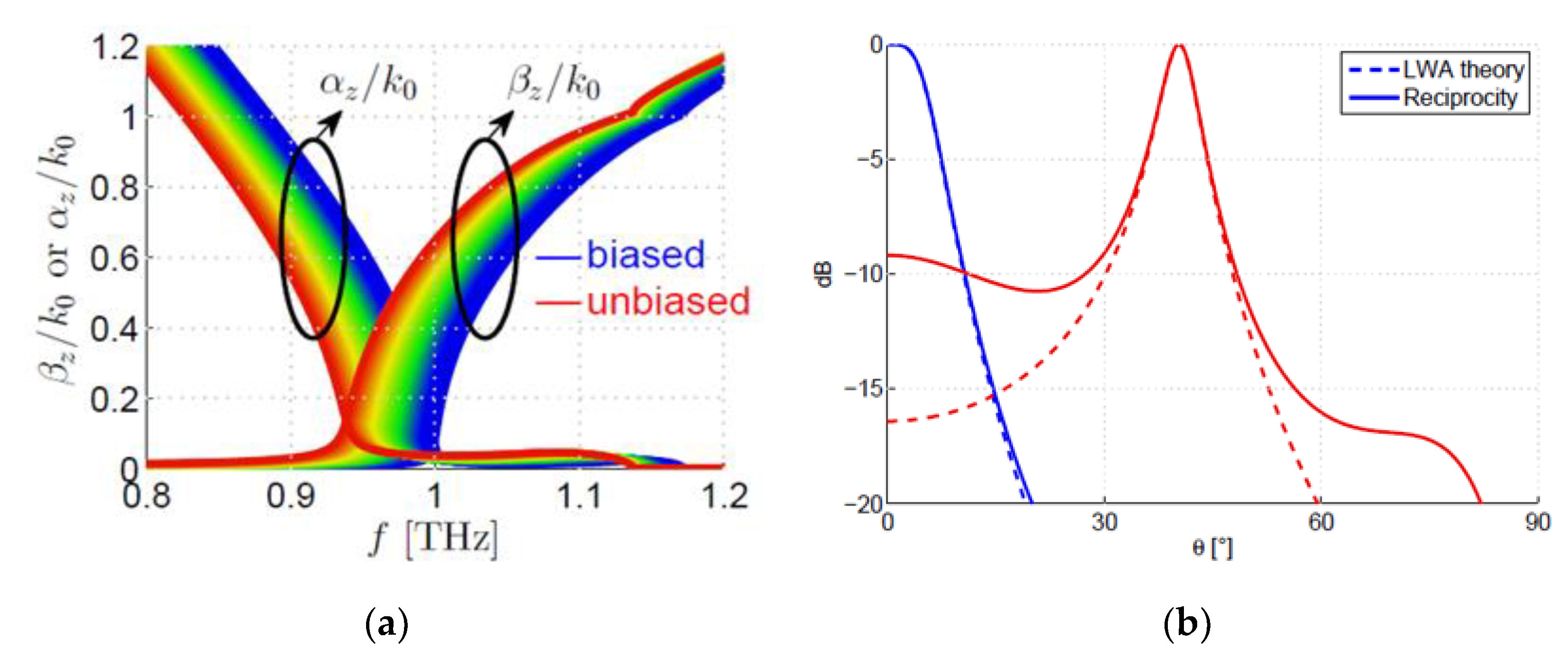
We can consider a multilayer FPC-LWA layout working at f0 = 1 THz, as a case of study able to underline the excellent reconfigurable properties of the proposed structure [42]. The number of layers that constitutes the stack is fixed at 5, i.e., three alumina layers of thickness equal to 75 µm and two LC cells 100 µm thick. Dispersion curves computed between 0.8 and 1.2 THz by means of leaky-wave theory [55,56] are presented in Figure 3a. They are a family of curves obtained gradually changing the voltage between zero (red curve) and the threshold voltage V > VF (blue curve). From a numerical viewpoint, the voltage changing corresponds to a dielectric permittivity commutation as reported in Equation (12), where ε x ( V = 0 ) = ε , ε y ( V = 0 ) = ε , ε z ( V = 0 ) = ε , ε x ( V = V F ) = ε , ε y ( V = V F ) = ε , and ε z ( V = V F ) = ε . Intermediate results can be obtained for intermediate values of voltage, i.e., intermediate values of dielectric permittivity in the x- and z-directions. For the proposed LC cell thickness, values below 20 V are sufficient to cover almost the complete switching range, as can be derived from LC dynamic complex numerical models that take into account molecules’ orientation states at intermediate voltage values [57]. For simplifying the analysis, it is assumed that LC relative permittivity linearly varies with the applied voltage. For this reason, the unbiased and biased states are always correctly predicted. Conversely, the dynamic variation of β ^ z = β z / k 0 and α ^ z = α z / k 0 , corresponding to voltage values between 0 and 20 V, could change if the permittivity tensor is computed for the intermediate biasing states.
The frequency at which the splitting condition β ^ z α ^ z is achieved can be considered as the operating frequency. For this case of study, the operative frequency is fixed by the value obtained when the voltage is equal to V (blue curve), which corresponds to the design frequency. In fact, once the operating frequency is fixed, it is possible to change the value of the normalized phase constant β ^ z by simply decreasing the external voltage. On the contrary, the value of the normalized attenuation constant α ^ z remains almost the same, such that β ^ z > α ^ z . This would allow the steering of the THz beam with a quasi-constant beamwidth (because it is proportional to α ^ z that does not change with the voltage) at a fixed frequency.
The radiation patterns, computed by means of both leaky-wave theory and full-wave simulations [58], are reported in Figure 3b and confirm the results achieved from the dispersion analysis. The antenna excitation is modelled with an HMD placed on the ground plane. HMD source can be used to model a slot etched in the ground plane and back-illuminated by a coherent THz source, such as QCLs or photomixers. For deriving radiating patterns, two methods are used: (i) taking into account only the contribution of the relevant leaky mode (dash line) and (ii) computing them by means of full-wave simulations (solid line). Radiation pattern for the unbiasing state (blue lines) shows a very good agreement between LWA theory and simulations. However, in the biased state (red lines), the LWA theory does not provide an accurate evaluation. This is probably because a higher-order leaky-wave mode could be present, increasing the sidelobe level. Full-wave simulations, however, correctly predicts this effect. In fact, the thickness of the LC layers extends the range of tunability, but degrades the radiation patterns. In [42], some solutions that take into account different number of layers and different thickness of the layers are introduced and discussed.

4. Liquid Crystal Cell as a Grounded Dielectric Slab

An alternative strategy that can be employed for steering the beam emitted by an FPC-LWA consists in substituting the GDS with a slab of anisotropic material, i.e., with a layer of LC. In fact, an external voltage on the LC cell is able to tune the values of the nematic LC’s permittivity tensor, dynamically affecting the propagation properties of the modes supported by the grounded anisotropic dielectric slab (GADS). The starting point in the design of FPC-LWAs with an anisotropic substrate is to carry out a comprehensive analysis of the modal spectrum supported by a GADS. It constitutes a solid background for optimizing the performances of the GADS when it is covered by a PRS, i.e., when the radiation is enabled [59].

4.1. The Grounded Anisotropic Dielectric Slab Model

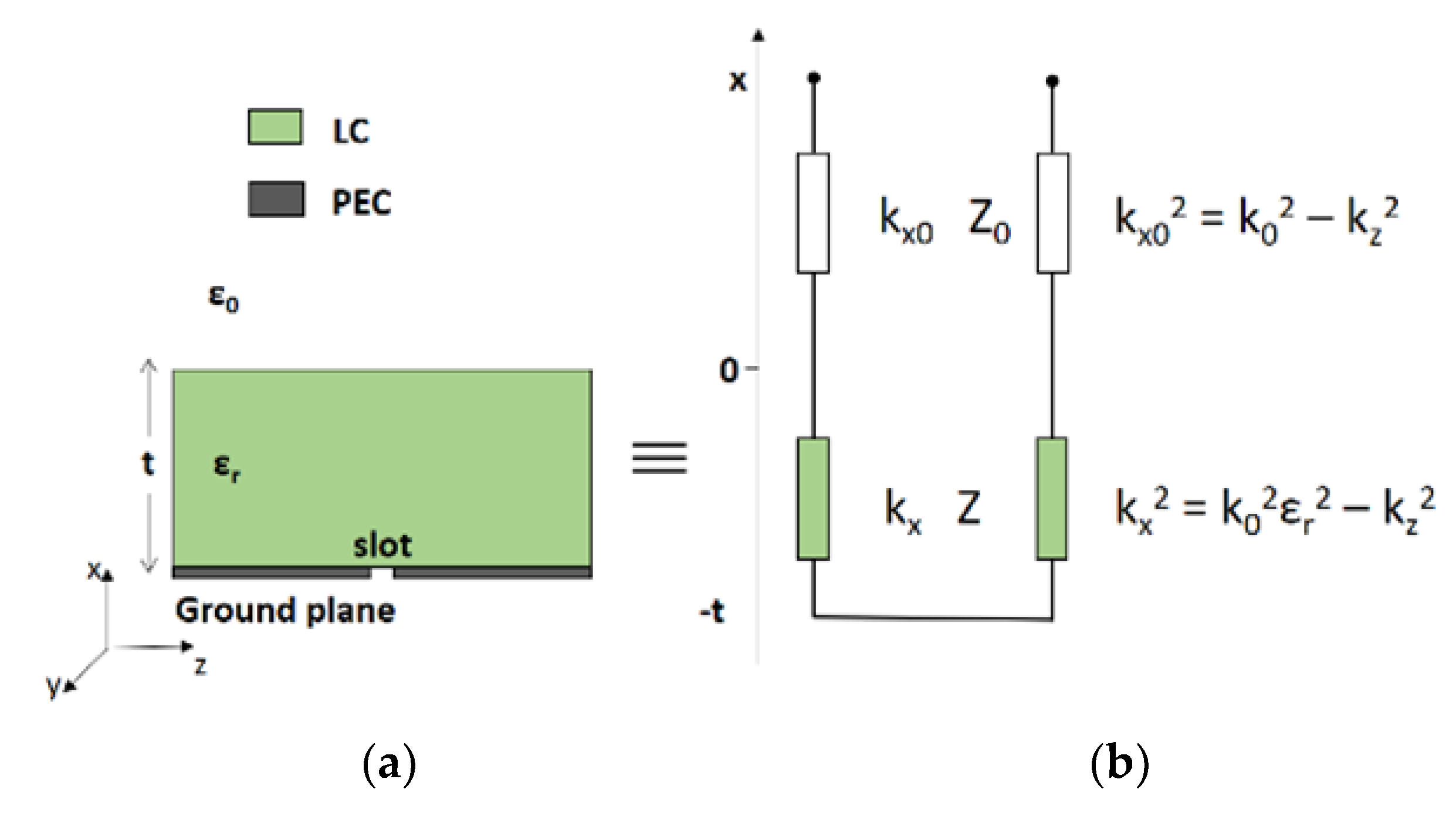
The analysis of both the leaky and the surface waves excited by an HMD and supported by the GADS is performed in the frequency range between 0.25 and 2 THz. As in the previous section, two limiting cases are numerically studied: the LCs are unbiased (V = 0) and a bias voltage that fully reorients the LC molecules is applied (V > VF). Again, the LC mixture 1825 is selected ( n o = 1.554 − j0.018 and n e = 1.941 − j0.022 at 1 THz, where n o = ε and n e = ε ). According to Equation (3) and considering a design frequency of 1 THz, the LC slab thickness is 96.5 µm. In this way, the LC layer is an FPC at 1 THz and the TE mode always experiments the FPC at 1 THz, even if the LC is biased. Figure 4 depicts the model employed in the study of the GADS complex mode spectra. The model consists of an air region, the LC slab and a ground considered as a perfect electric conductor (PEC). The electrodes for the LC biasing are neglected as a first approximation because they do not remarkably affect the modal analysis.
The modal analysis of the GADS can be carried out by means of the TRT applied to the equivalent network of the structure, as described in Section 2.3. However, the simple TEN model of Figure 4a is a good approximation of more rigorous models developed in literature [60,61] when the LCs are uniaxial and their ε and ε differ less than 50%. The characteristic admittances and the normal wavenumbers of the LC layer for both the TE and the TM polarizations (with respect to the xz-plane) are the same as in Equations (13) and (14). The selected LC mixture is uniaxial and εy does not depend on the applied voltage. Equation (4) evaluated at x = 0 gives the following dispersion equation for the TM mode of the GADS:
j Y TM cot ( k x , 0 h 0 ) = Y 0 TM
where Y0TM is the TM characteristic admittance in the air.

4.2. Modal Spectra of Grounded Isotropic and Anisotropic Dielectric Slab

The modal analysis involves two structures: the GDS and the GADS. In the GDS, the permittivity has an isotropic value and it is equal to either ε r = ε , or ε r = ε ; in the GADS, the permittivity is the tensor of Equation (12). The complex mode spectra resulting from the dispersion analysis are presented in Figure 5 and are slightly different between the GDS and GADS, confirming the importance to modeling the permittivity of the substrate as a tensor. The normalized phase constant of the surface-wave modes (SW) does not show significant variations between the GDS and the GADS models. The leaky-wave modes (LW) are characterized by values of the normalized attenuation constant that never decrease below 0.75. For this reason, the LW cannot represent a contribution to the radiation and the grounded slabs need to be covered by a PRS for working as antennas. This aspect will be investigated in the future. However, the normalized phase constant (related to the FPC-LWA pointing angle, as expressed in Equation (1)) of the LW shows a significant variation due to the birefringence of the selected LC mixture. This suggests that the GADS once equipped of a PRS may represent an interesting solution for performing the beam steering of the THz radiation.
The analysis presented in Figure 5 is a preliminary numerical study that may constitute a solid background for the experimental implementation of LC-substrate FPC-LWAs with THz beam-steering capabilities.

5. Graphene Fabry–Perot Cavity Leaky Wave Antennas for THz Beam Steering

In the previous examples, we have seen how it is possible to enhance beam-steering capabilities at fixed frequency in FPC-LWAs by exploiting the tunable features of liquid crystals. However, in such LC-based devices, the beam can only be steered along a principal plane, namely the E-plane, since only TM leaky modes are affected by the axis re-orientation of the LC permittivity sensor. In order to fully switch from a pencil beam to a conical beam, both TM and TE leaky modes need to be affected by the application of a bias voltage. Remarkably, graphene-based FPC-LWAs have recently been shown to effectively provide for such radiating features [62,63,64]. Indeed, one of the most intriguing features exhibited by graphene (the two-dimensional version of graphite) is the electrical field-effect, i.e., the capability to change its surface conductivity (which completely describes its electrical properties, being graphene a 2Dmaterial) through the application of a bias voltage [65]. In particular, in the THz range, graphene exhibits moderate ohmic losses and a wide variation of reflectivity as the bias is raised from zero (very low reflectivity) to tens of Volts (moderate/high reflectivity) [66]. Interestingly, in the low THz range and for fast waves (as radiating leaky waves), graphene exhibits the same surface conductivity for both TM and TE polarization [67]. As a consequence, when a bias voltage is applied to graphene, both TM and TE leaky modes are affected, and to the radiating features along the principal E- and H-plane, respectively [63,68,69,70]. Two relatively simple realizations of graphene-based FPC-LWAs are the graphene planar waveguide (GPW) [68] and the graphene substrate superstrate (GSS) [69].

5.1. Graphene Planar Waveguide

A GPW is the simplest configuration of graphene-based FPC-LWAs. In practice, the PRS is represented by a uniform graphene sheet that is placed above a λ/2 thick grounded dielectric slab (usually silicon oxide), fed through a sub-resonant slot etched in the ground-plane and back-illuminated by a THz source (as depicted in Figure 1). The graphene sheet can be biased by placing a thin layer of a low-loss THz conductive polymer beneath the graphene sheet and contacting the layers with two electrodes (see Figure 6a). The greatest the bias voltage, the highest would be the reflectivity of the graphene sheet [68]. However, the value of the maximum bias voltage depends on the voltage breakdown of the dielectric filling the gap between graphene sheet and the conductive polymer (see Section IV in [63] for an in-depth discussion). For antenna applications, a value of bias voltage that raises the chemical potential of graphene up to 1 eV is considered a good trade-off (an approximate relation between the chemical potential and the bias voltage can be found e.g., in [40,66,68]). In particular, in the case of the GPW studied in [68], when the graphene chemical potential is raised to 1 eV, the GPW radiates a pencil beam at broadside. By progressively lowering the bias, the beam evolves in a conical beam reaching a maximum angle that is dictated by both the graphene quality and the substrate material (see Figure 6b–c). In this regard, we should mention that graphene quality considerably affects the antenna radiating features, and very high quality graphene flakes are needed to achieve a satisfactory performance with a GPW. However, even using high-quality graphene, a GPW is not capable of radiating highly-directive beams. This limitation is due to the both the non-negligible ohmic losses of graphene and the moderate values of its reflectivity. Therefore, in order to improve directivity in graphene-based FPC-LWAs, a PRS with a higher reflectivity is needed. This idea is realized in the GSS [69].

5.2. Graphene Substrate Superstrate

In a GSS, a λ/4 thick superstrate layer of a high refractive index material (e.g., Hafnium Oxide) is placed on top of the low-refractive index dielectric substrate, whereas the graphene sheet is lowered down to an optimal position between the ground plane and the substrate-superstrate interface (see Figure 7a). Such an optimal position can be retrieved from semi-analytical approaches
where the objective function is represented by the search of a position that maximizes directivity at broadside [69]. The result is a position in a middle-of-the-way between the substrate–superstrate interface (where the interaction between graphene and the tangential electric modal field is expected to be minimum) and the middle of the substrate (where the interaction between graphene and the tangential electric modal field is expected to be maximum). The reason for this result lies in the graphene electrical properties: the optimal position has to counterbalance the benefits of graphene tenability and reflectivity with the drawbacks of graphene ohmic losses, whose effects are more prominent in the points of maximum interaction with the electric field (see the relevant discussion in [63]). As a result, the GSS exhibits a higher directivity and a slightly reduced rate of reconfigurability with respect to the GPW (see Figure 7b–c). Nevertheless, the GSS offers more degrees of freedom to design FPC-LWAs with certain radiating features. In both cases, the quality of graphene plays a crucial role, and this aspect is still hindering a first experimental validation of these concepts.

6. Conclusions

Leaky-wave antennas are fast traveling-wave antennas, in which radiation occurs thanks to a power leakage during the wave propagation. They are antennas characterized by a high directivity and by the possibility to be employed as radiating systems at microwaves as well as at optical frequencies. For these reasons, LWAs seem to be particularly suitable for being integrated in THz systems. Among the several existing LWAs typologies, FPC-LWAs are attractive structures because they allow for tuning the radiating features by applying an external voltage. In this review, some strategies for implementing a reconfiguration of the emitting radiation have been discussed and some examples have been analyzed.

Author Contributions

Writing—Original draft preparation, S.T.; writing—review and editing, S.T. and W.F.; supervision, W.F. All authors have read and agreed to the published version of the manuscript.

Funding

This research received no external funding.

Acknowledgments

The authors would like to thank A. Galli, P. Burghignoli, P. Baccarelli, R. Beccherelli, and D.C. Zografopoulos for their valuable contributions on the topic of the current short Review.

Conflicts of Interest

The authors declare no conflict of interest.

References

  1. Dhillon, S.S.; Vitiello, M.S.; Linfield, E.H.; Davies, A.G.; Hoffmann, M.C.; Booske, J.; Paoloni, C.; Gensch, M.; Weightman, P.; Williams, G.P.; et al. The 2017 terahertz science and technology roadmap. J. Phys. D Appl. Phys. 2017, 50, 043001. [Google Scholar] [CrossRef]
  2. Tu, W.; Zhong, S.; Shen, Y.; Incecik, A. Nondestructive testing of marine protective coatings using terahertz waves with stationary wavelet transform. Ocean Eng. 2016, 111, 582–592. [Google Scholar] [CrossRef] [Green Version]
  3. Heinz, E.; May, T.; Born, D.; Zieger, G.; Anders, S.; Zakosarenko, V.; Meyer, H.-G.; Schäffel, C. Passive 350 GHz video imaging systems for security applications. J. Infrared Millim. Terahertz Waves 2015, 36, 879–895. [Google Scholar] [CrossRef]
  4. Leahy-Hoppa, M.R.; Fitch, M.J.; Zheng, X.; Hayden, L.M.; Osiander, R. Wideband terahertz spectroscopy of explosives. Chem. Phys. Lett. 2007, 434, 227–230. [Google Scholar] [CrossRef]
  5. Haglund, R.F.; Neev, J.; Wood, R.F. Commercial and biomedical applications of ultrashort pulse lasers; laser plasma generation and diagnostics. In Proceedings of the SPIE, San Jose, CA, USA, 29 May 2001. [Google Scholar] [CrossRef]
  6. Rappaport, T.S.; Murdock, J.N.; Gutierrez, F. State of the Art in 60-GHz Integrated Circuits and Systems for Wireless Communications. Proc. IEEE 2011, 99, 1390–1436. [Google Scholar] [CrossRef]
  7. Miles, R.; Zhang, X.-C.; Eisele, H.; Krotkus, A. Terahertz Frequency Detection and Identification of Materials and Objects; Springer Science & Business Media: Berlin/Heidelberg, Germany, 2007; ISBN 978-1-4020-6503-3. [Google Scholar]
  8. Akyildiz, I.F.; Jornet, J.M.; Han, C. Terahertz band: Next frontier for wireless communications. Phys. Com. 2014, 12, 16–32. [Google Scholar] [CrossRef]
  9. Monticone, F.; Alù, A. Leaky-wave theory, techniques, and applications: From microwaves to visible frequencies. Proc. IEEE 2015, 103, 793–821. [Google Scholar] [CrossRef]
  10. Tamir, T.; Oliner, A.A. Guided complex waves. Part 1: Fields at an interface. Proc. Inst. Electr. Eng. 1963, 110, 310–324. [Google Scholar] [CrossRef]
  11. Tamir, T.; Oliner, A.A. Guided complex waves. Part 2: Relation to radiation patterns. Proc. Inst. Electr. Eng. 1963, 110, 325–334. [Google Scholar] [CrossRef]
  12. Croswell, W.; Zucker, F.J. Surface-wave antennas. In Antenna Engineering Handbook; Volakis, J.L., Ed.; McGraw-Hill: New York, NY, USA, 2007; Chapter 10. [Google Scholar]
  13. Jackson, D.R.; Oliner, A.A. Leaky-wave antennas. In Modern Antenna Handbook; Balanis, C.A., Ed.; John Wiley & Sons, Inc.: Hoboken, NJ, USA, 2008; pp. 325–367. ISBN 978-0-470-29415-4. [Google Scholar]
  14. Galli, A.; Baccarelli, P.; Burghignoli, P. Leaky-Wave Antennas. In Wiley Encyclopedia of Electrical and Electronics Engineering; Webster, J.G., Ed.; John Wiley & Sons, Inc.: Hoboken, NJ, USA, 2016; ISBN 978-0-471-34608-1. [Google Scholar]
  15. Fuscaldo, W.; Tofani, S.; Burghignoli, P.; Baccarelli, P.; Galli, A. Terahertz leaky-wave antennas based on metasurfaces and tunable materials. In Metamaterials and Metasurfaces; Canet-Ferrer, J., Ed.; IntechOpen: London, UK, 2018; pp. 93–116. [Google Scholar]
  16. von Trentini, G. Partially reflecting sheet arrays. IEEE Trans. Antennas Propag. 1956, 4, 666–671. [Google Scholar] [CrossRef]
  17. Ip, A.; Jackson, D.R. Radiation from cylindrical leaky waves. IEEE Trans. Antennas Propag. 1990, 38, 482–488. [Google Scholar] [CrossRef]
  18. Zhao, T.; Jackson, D.R.; Williams, J.T.; Oliner, A.A. General formulas for 2Dleaky-wave antennas. IEEE Trans. Antennas Propag. 2005, 53, 3525–3533. [Google Scholar] [CrossRef]
  19. Feresidis, A.P.; Vardaxoglou, J.C. High gain planar antenna using optimised partially reflective surfaces. IEE Proc. Microwaves Antennas Propag. 2001, 148, 345–350. [Google Scholar] [CrossRef]
  20. Lovat, G.; Burghignoli, P.; Jackson, D.R. Fundamental properties and optimization of broadside radiation from uniform leaky-wave antennas. IEEE Trans. Antennas Propag. 2006, 54, 1442–1452. [Google Scholar] [CrossRef]
  21. Luukkonen, O.; Simovski, C.; Granet, G.; Goussetis, G.; Lioubtchenko, D.; Raisanen, A.V.; Tretyakov, S.A. Simple and accurate analytical model of planar grids and high-impedance surfaces comprising metal strips or patches. IEEE Trans. Antennas Propag. 2008, 56, 1624–1632. [Google Scholar] [CrossRef] [Green Version]
  22. Itoh, T. Numerical Techniques for Microwave and Millimeter-Wave Passive Structures; Wiley-Interscience: Hoboken, NJ, USA, 1989. [Google Scholar]
  23. Sorrentino, R. Numerical Methods for Passive Microwave and Millimeter Wave Structures; IEEE Press: New York, NY, USA, 1989. [Google Scholar]
  24. Felsen, L.B.; Marcuvitz, N. Radiation and Scattering of Waves; John Wiley & Sons: Hoboken, NJ, USA, 1994; ISBN 978-0-7803-1088-9. [Google Scholar]
  25. Goldstone, L.; Oliner, A. Leaky-wave antennas I: Rectangular waveguides. IRE Trans. Antennas Propag. 1959, 7, 307–319. [Google Scholar] [CrossRef]
  26. Pozar, D.M. Microwave Engineering; Wiley India Pvt. Limited: Delhi, India, 2009; ISBN 978-81-265-1049-8. [Google Scholar]
  27. Alonso-delPino, M.; Reck, T.; Jung-Kubiak, C.; Lee, C.; Chattopadhyay, G. Development of silicon micromachined microlens antennas at 1.9 THz. IEEE Trans. Terahertz Sci. Technol. 2017, 7, 191–198. [Google Scholar] [CrossRef]
  28. Llombart, N.; Chattopadhyay, G.; Skalare, A.; Mehdi, I. Novel terahertz antenna based on a silicon lens fed by a leaky wave enhanced waveguide. IEEE Trans. Antennas Propag. 2011, 59, 2160–2168. [Google Scholar] [CrossRef]
  29. Hussain, N.; Park, I. Optimization of a small lens for a leaky-wave slit dipole antenna at the terahertz band. In Proceedings of the 2016 International Symposium on Antennas and Propagation (ISAP), Okinawa, Japan, 24–28 October 2016; pp. 782–783. [Google Scholar]
  30. Neto, A.; Llombart, N.; Baselmans, J.J.A.; Baryshev, A.; Yates, S.J.C. Demonstration of the leaky lens antenna at submillimeter wavelengths. IEEE Trans. Terahertz Sci. Technol. 2014, 4, 26–32. [Google Scholar] [CrossRef]
  31. Bueno, J.; Yurduseven, O.; Yates, S.J.C.; Llombart, N.; Murugesan, V.; Thoen, D.J.; Baryshev, A.M.; Neto, A.; Baselmans, J.J.A. Photon noise limited performance over an octave of bandwidth of kinetic inductance detectors for sub-millimeter astronomy. In Proceedings of the 2016 41st International Conference on Infrared, Millimeter, and Terahertz waves (IRMMW-THz), Copenhagen, Denmark, 25–30 September 2016; pp. 1–2. [Google Scholar]
  32. Llombart, N.; Bueno, J.; Yurduseven, O.; Baselmans, J.; Neto, A. Dual polarized leaky wave antenna coupled KIDs for THz space applications. In Proceedings of the 2014 39th International Conference on Infrared, Millimeter, and Terahertz waves (IRMMW-THz), Millimeter, Tucson, AZ, USA, 14–19 September 2014; pp. 1–2. [Google Scholar]
  33. Hussain, N.; Park, I. Design of a wide-gain-bandwidth metasurface antenna at terahertz frequency. AIP Adv. 2017, 7, 055313. [Google Scholar] [CrossRef] [Green Version]
  34. Hussain, N.; Nguyen, T.K.; Park, I. Performance comparison of a planar substrate-integrated Fabry-Perot cavity antenna with different unit cells at terahertz frequency. In Proceedings of the 2016 10th European Conference on Antennas and Propagation (EuCAP), Davos, Switzerland, 10–15 April 2016; pp. 1–4. [Google Scholar]
  35. Nguyen, T.K.; Ta, B.Q.; Park, I. Design of a planar, high-gain, substrate-integrated Fabry–Perot cavity antenna at terahertz frequency. Curr. Appl. Phy. 2015, 15, 1047–1053. [Google Scholar] [CrossRef]
  36. Fuscaldo, W.; Tofani, S.; Zografopoulos, D.C.; Baccarelli, P.; Burghignoli, P.; Beccherelli, R.; Galli, A. Systematic design of THz leaky-wave antennas based on homogenized metasurfaces. IEEE Trans. Antennas Propag. 2018, 66, 1169–1178. [Google Scholar] [CrossRef]
  37. Tofani, S.; Fuscaldo, W.; Zografopoulos, D.C.; Burghignoli, P.; Baccarelli, P.; Beccherelli, R.; Galli, A. Design-flow of Fabry-Perot cavity leaky-wave antennas based on homogenized metasurfaces. In Proceedings of the 2019 13th European Conference on Antennas and Propagation (EuCAP), Krakow, Poland, 31 March–5 April 2019; pp. 1–4. [Google Scholar]
  38. Tofani, S.; Fuscaldo, W.; Zografopoulos, D.C.; Baccarelli, P.; Burghignoli, P.; Beccherelli, R.; Galli, A. Spatial Dispersion Analysis of Homogenized Metafurfaces for Terahertz Leaky-wave Antennas. In Proceedings of the 12th European Conference on Antennas and Propagation (EuCAP 2018), London, UK, 9–13 April 2018. [Google Scholar]
  39. Li, J.; He, M.; Wu, C.; Zhang, C. Radiation-pattern-reconfigurable graphene leaky-wave antenna at terahertz band based on dielectric grating structure. IEEE Antennas Wirel. Propag. Lett. 2017, 16, 1771–1775. [Google Scholar] [CrossRef]
  40. Esquius-Morote, M.; Gómez-Diaz, J.S.; Perruisseau-Carrier, J. Sinusoidally modulated graphene leaky-wave antenna for electronic beamscanning at THz. IEEE Trans. Terahertz Sci. Technol. 2014, 4, 116–122. [Google Scholar] [CrossRef] [Green Version]
  41. Cheng, J.; Jafar-Zanjani, S.; Mosallaei, H. Real-time two-dimensional beam steering with gate-tunable materials: A theoretical investigation. Appl. Opt. 2016, 55, 6137–6144. [Google Scholar] [CrossRef]
  42. Fuscaldo, W.; Tofani, S.; Zografopoulos, D.C.; Baccarelli, P.; Burghignoli, P.; Beccherelli, R.; Galli, A. Tunable Fabry-Perot cavity THz antenna based on leaky-wave propagation in nematic liquid crystals. IEEE Antennas Wirel. Propag. Lett. 2017, 16, 2046–2049. [Google Scholar] [CrossRef]
  43. Murano, K.; Watanabe, I.; Kasamatsu, A.; Suzuki, S.; Asada, M.; Withayachumnankul, W.; Tanaka, T.; Monnai, Y. Demonstration of short-range terahertz radar using high-gain leaky-wave antenna. In Proceedings of the 2016 41st International Conference on Infrared, Millimeter, and Terahertz waves (IRMMW-THz), Copenhagen, Denmark, 25–30 September 2016; pp. 1–2. [Google Scholar]
  44. Murano, K.; Watanabe, I.; Kasamatsu, A.; Suzuki, S.; Asada, M.; Withayachumnankul, W.; Tanaka, T.; Monnai, Y. Low-profile terahertz radar based on broadband leaky-wave beam steering. IEEE Trans. Terahertz Sci. Technol. 2017, 7, 60–69. [Google Scholar] [CrossRef]
  45. Chamberlain, J.M. Where optics meets electronics: Recent progress in decreasing the terahertz gap. Philos. Trans. R. Soc. A 2004, 362, 199–213. [Google Scholar] [CrossRef]
  46. Holloway, C.L.; Kuester, E.F.; Gordon, J.A.; O’Hara, J.; Booth, J.; Smith, D.R. An overview of the theory and applications of metasurfaces: The two-dimensional equivalents of metamaterials. IEEE Antennas Propag. Mag. 2012, 54, 10–35. [Google Scholar] [CrossRef]
  47. Khoo, I.-C. Liquid Crystals: Physical Properties and Nonlinear Optical Phenomena; John Wiley & Sons: Hoboken, NJ, USA, 2007; ISBN 978-0-470-08402-1. [Google Scholar]
  48. Chandrasekhar, S. Liquid Crystals; Cambridge University Press: Cambridge, UK, 1992; ISBN 978-0-521-42741-8. [Google Scholar]
  49. Berreman, D.W. Solid surface shape and the alignment of an adjacent nematic liquid crystal. Phys. Rev. Lett. 1972, 28, 1683–1686. [Google Scholar] [CrossRef]
  50. Yaroshchuk, O.; Reznikov, Y. Photoalignment of liquid crystals: Basics and current trends. J. Mater. Chem. 2011, 22, 286–300. [Google Scholar] [CrossRef]
  51. Fréedericksz, V.; Zolina, V. Forces causing the orientation of an anisotropic liquid. Trans. Faraday Soc. 1933, 29, 919–930. [Google Scholar] [CrossRef]
  52. Dąbrowski, R.; Kula, P.; Herman, J. High birefringence liquid crystals. Crystals 2013, 3, 443–482. [Google Scholar] [CrossRef]
  53. Reuter, M.; Vieweg, N.; Fischer, B.M.; Mikulicz, M.; Koch, M.; Garbat, K.; Dąbrowski, R. Highly birefringent, low-loss liquid crystals for terahertz applications. APL Mater. 2013, 1, 012107. [Google Scholar] [CrossRef]
  54. Jackson, D.R.; Oliner, A.A.; Ip, A. Leaky-wave propagation and radiation for a narrow-beam multiple-layer dielectric structure. IEEE Trans. Antennas Propag. 1993, 41, 344–348. [Google Scholar] [CrossRef]
  55. Fuscaldo, W. Advanced Radiating Systems Based on Leaky Waves and Nondiffracting Waves. Ph.D. thesis, 2017. [Google Scholar]
  56. Tofani, S. Static and reconfigurable devices for near-field and far-field terahertz applications. Ph.D. thesis, Sapienza University of Rome, Rome, Italy, 2018. [Google Scholar]
  57. Zografopoulos, D.C.; Beccherelli, R.; Kriezis, E.E. Beam-splitter switches based on zenithal bistable liquid-crystal gratings. Phys. Rev. E 2014, 90, 042503. [Google Scholar] [CrossRef] [PubMed]
  58. CST. Available online: https://www.cst.com/ (accessed on 9 May 2017).
  59. Tofani, S.; Fuscaldo, W.; Zografopoulos, D.C.; Burghignoli, P.; Baccarelli, P.; Beccherelli, R.; Galli, A. Terahertz modal analysis of a grounded liquid-crystal cell and its application as a tunable cavity antenna. In Proceedings of the 2019 41st Photonics and Electromagnetics Research Symposium (PIERS), Rome, Italy, 17–20 June 2019. [Google Scholar]
  60. Yakovlev, A.B.; Hanson, G.W. Fundamental modal phenomena on isotropic and anisotropic planar slab dielectric waveguides. IEEE Trans. Antennas Propag. 2003, 51, 888–897. [Google Scholar] [CrossRef]
  61. Pavone, S.C.; Martini, E.; Caminita, F.; Albani, M.; Maci, S. Surface Wave Dispersion for a Tunable Grounded Liquid Crystal Substrate Without and With Metasurface on Top. IEEE Trans. Antennas Propag. 2017, 65, 3540–3548. [Google Scholar] [CrossRef]
  62. Wang, X.-C.; Zhao, W.-S.; Hu, J.; Yin, W.-Y. Reconfigurable Terahertz Leaky-Wave Antenna Using Graphene-Based High-Impedance Surface. IEEE Trans. Nanotechnol. 2015, 14, 62–69. [Google Scholar] [CrossRef]
  63. Fuscaldo, W.; Burghignoli, P.; Baccarelli, P.; Galli, A. Graphene Fabry-Perot cavity leaky-wave antennas: Plasmonic versus nonplasmonic solutions. IEEE Trans. Antennas Propag. 2017, 65, 1651–1660. [Google Scholar] [CrossRef]
  64. Fuscaldo, W.; Tofani, S.; Burghignoli, P.; Baccarelli, P.; Notargiacomo, A.; Cibella, S.; Pea, M.; Carelli, P.; Mishra, N.; Coletti, C.; et al. Graphene-Based Fabry-Perot Cavity Leaky-Wave Antennas: Towards an Experimental Validation. In Proceedings of the 2018 48th European Microwave Conference (EuMC), Madrid, Spain, 25–27 September 2018; pp. 276–279. [Google Scholar]
  65. Geim, A.K.; Novoselov, K.S. The rise of graphene. Nat. Mater. 2007, 6, 183–191. [Google Scholar] [CrossRef] [PubMed]
  66. Hanson, G.W. Dyadic Green’s functions for an anisotropic, non-local model of biased graphene. IEEE Trans. Antennas Propag. 2008, 56, 747–757. [Google Scholar] [CrossRef]
  67. Lovat, G.; Hanson, G.W.; Araneo, R.; Burghignoli, P. Semiclassical spatially dispersive intraband conductivity tensor and quantum capacitance of graphene. Phys. Rev. B 2013, 87, 115429. [Google Scholar] [CrossRef]
  68. Fuscaldo, W.; Burghignoli, P.; Baccarelli, P.; Galli, A. Complex mode spectra of graphene-based planar structures for THz applications. J. Infrared Milli. Terahz Waves 2015, 36, 720–733. [Google Scholar] [CrossRef] [Green Version]
  69. Fuscaldo, W.; Burghignoli, P.; Baccarelli, P.; Galli, A. A Reconfigurable Substrate-Superstrate Graphene-Based Leaky-Wave THz Antenna. IEEE Antennas Wirel. Propag. Lett. 2016, 15, 1545–1548. [Google Scholar] [CrossRef]
  70. Fuscaldo, W.; Tofani, S.; Burghignoli, P.; Baccarelli, P.; Galli, A. Terahertz Fabry-Perot cavity leaky-wave antennas. In Proceedings of the 2019 41st Photonics and Electromagnetics Research Symposium (PIERS), Rome, Italy, 17–20 June 2019. [Google Scholar]
Figure 1. (a) an example of FPC-LWA fed by an HMD (horizontal magnetic dipole) oriented along the y-axis [15]; (b) terminated equivalent network representing a waveguide cross-section [13]. An FPC-LWA is constituted by a dielectric substrate with a metallization (i.e., a mirror) on the bottom (grounded dielectric slab, GDS) and a PRS (partially reflective surface) on top. A slot for antenna excitation is etched on the metalized side of the substrate. Note that a back-illuminated quasi-resonant slot can be modeled as an equivalent horizontal magnetic dipole (HMD).
Condensedmatter 05 00011 g001
Figure 2. (a) cross-section and (b) equivalent network of a multilayer FPC-LWA with nematic LC cells (NLC) [42].
Condensedmatter 05 00011 g002
Figure 3. (a) dispersion curves of the fundamental TM mode computed by means of leaky-wave theory [55,56]; (b) radiation patterns predicted by leaky-wave theory (dashed lines) or by means of full-wave simulations with CST (solid lines) [55,56,58].
Condensedmatter 05 00011 g003
Figure 4. (a) cross-section of the model of the GADS and (b) its equivalent circuit network [59].
Condensedmatter 05 00011 g004
Figure 5. (a) normalized phase constant and (b) normalized attenuation constant spectra of the TM modes of a GDS (black and gray lines) and a GADS (red and blue lines) obtained by changing the values in the LC permittivity tensor. Proper modes are depicted in solid lines, physical and nonphysical improper complex modes are represented in dotted and dashed lines, respectively [59].
Condensedmatter 05 00011 g005
Figure 6. (a) a sketch of the GPW described in 5.1 [55]. In (b,c), the evolution from a pencil beam to a conical beam as the chemical potential is lowered from 1 eV to 0.5 eV, respectively [70]. The radiation patterns are obtained through CST full-wave simulations [58].
Condensedmatter 05 00011 g006
Figure 7. (a) a sketch of the GSS described in 5.2 [55]. In (b) and (c), the evolution from a pencil beam to a conical beam as the chemical potential is lowered from 1 eV to 0.3 eV, respectively [70]. The radiation patterns are obtained through CST full-wave simulations [58].
Condensedmatter 05 00011 g007