1. Introduction
Current research on fish sorting devices spans multiple critical areas, including fish passage in fishways, behavioral conditioning, feeding management, and processing and sorting [
1,
2,
3,
4,
5,
6]. In fishway design, researchers have achieved uniform flow velocity distribution by optimizing hydraulic structures, effectively improving fish passage rates. In the field of behavioral control, techniques such as conditioning and flow simulation have significantly enhanced fish aggregation response and residence time. Concurrently, advancements in automated processing equipment have led to marked improvements in cutting precision and sorting efficiency, providing crucial support for intensive aquaculture and mechanized processing [
7,
8,
9,
10,
11]. However, existing devices, often based on mechanical screening or flow guidance principles, still exhibit limitations in processing efficiency, sorting accuracy, and adaptability to fish of varying sizes, necessitating the introduction of novel technological approaches to overcome these challenges.
In 2014, Wang Xinlei et al. [
12] investigated the hydraulic characteristics of a novel spiral fishway, finding that the flow velocity distribution within the spiral fishway was uniform, with a maximum velocity of 1.2 m/s, meeting the requirements for fish passage. In 2017, Hu Xiaobo et al. [
13] studied a bidirectional rotating hydropower screw fishway technology, demonstrating that the device enabled bidirectional fish passage, controlled flow velocity between 0.5–1.0 m/s, and effectively improved fish passage efficiency. In 2025, Hao Bohan [
14] investigated the design of an automated integrated fish cutting and splitting mechanical device, achieving a cutting accuracy of ±0.5 mm, a 30% increase in processing efficiency, and a significant reduction in labor costs. In 2026, Long Taoyuan et al. [
15] studied a device for monitoring fish feeding activity based on vibration signals, achieving a monitoring accuracy of 92.5%, enabling real-time feedback on feeding status, and effectively guiding precise feeding. In 2025, Han Deqiang [
16] investigated a fish circular swimming display device and technology, finding that the device simulated natural flow environments, extended fish residence time by 40%, and significantly enhanced display effectiveness. In 2023, Hu Qingsong et al. [
17] studied the design and experimentation of an EVA-based acoustic conditioning device for fish, achieving a reduced aggregation response time of 15 s post-conditioning, an aggregation rate of 85%, and effectively improving feeding efficiency. In 2019, Liu Jiafeng [
18] studied a feeding device for pond fish culture, obtaining results showing uniform feeding, timed and quantitative control capabilities, and effective reduction of feed waste. In 2022, Chen Xuewu [
19] investigated a sorting device for fish product processing, achieving a sorting accuracy of 98%, a processing capacity of 500 kg/h, and effectively improving processing efficiency.
Cyclone separation technology, as a method for efficient classification based on centrifugal force, has seen research focused on structural optimization, flow field regulation, and separation performance enhancement. By improving the separation chamber structure and introducing innovative designs such as double-cylinder or elliptical-cylinder configurations, researchers have effectively increased the separation efficiency of target materials while reducing system energy loss. The widespread application of numerical simulation has enabled the clear elucidation of particle trajectories and separation mechanisms for materials with varying characteristics within cyclone separators, leading to continuous improvement in the accuracy of predictive models. These research findings indicate that cyclone separation technology, leveraging its core advantage of efficient classification via centrifugal force, demonstrates excellent controllability and adaptability in the sorting and classification of various materials, suggesting its potential for application in the field of fish separation.
In 2025, Xu Yang et al. [
20] investigated the influence of dust discharge structure on cyclone separator performance, finding that the optimized structure increased separation efficiency to 94.2% and reduced pressure drop by 12.5%. In 2025, Tong Lingmiao [
21] conducted numerical simulations of gas-solid two-phase flow in a cyclone separator based on CFD-DPM, obtaining results showing separation efficiency below 70% for particles smaller than 5 μm, with efficiency significantly increasing for larger particle sizes. In 2025, Zheng Yuanbo [
22] studied the flow field characteristics and separation performance of a dual-diversion intensified cyclone separator, achieving a separation efficiency of 96.8% and a 15.3% reduction in pressure drop. In 2025, Guo Heng [
23] investigated the dust separation characteristics and structural design of a micro cyclone separator, obtaining a separation efficiency of 93.5% for 10 μm particles, suitable for small-scale dust removal scenarios. In 2025, Wang Xiaokang et al. [
24] conducted simulations and experiments on a plot-scale corn cyclone separator, achieving a separation efficiency of 95.2% for corn kernels and an entrainment rate below 3%. In 2024, Wang Zhongchen et al. [
25] studied the separation efficiency of cyclone separators, finding that the highest efficiency, reaching 96%, occurred at inlet velocities between 18–22 m/s, with particle concentration significantly influencing efficiency. In 2024, Zhu Zhenxing et al. [
26] investigated the separation performance and flow field of a novel double-cylinder cyclone separator, achieving a separation efficiency of 97.3% and an 18.6% reduction in pressure drop. In 2024, Feng Mengjing [
27] conducted structural design and performance optimization of a novel cyclone separator based on numerical simulation, achieving an increased separation efficiency for 5 μm particles to 82.4% and improved overall performance. In 2024, Chen Jiyuan et al. [
28] studied prediction models for cyclone separator efficiency, establishing a model with a prediction error of less than 5%, capable of accurately predicting separation efficiency under different operating conditions. In 2024, Yang Huandi [
29] investigated the flow field characteristics and separation performance of an elliptical cyclone separator, achieving a separation efficiency of 94.7% and a 10.2% reduction in pressure drop. In 2024, Tang Hongyu et al. [
30] predicted cyclone separator efficiency using the FA-ISSA-PPR model, achieving a prediction accuracy of 98.3%, surpassing traditional prediction methods.
Synthesizing the characteristics of the aforementioned two technological domains, this paper proposes to integrate existing fish sorting devices with cyclone separation principles to conduct simulation and prediction research on a novel fish sorting device. The specific concept involves adapting the principle of cyclone separation technology, which utilizes centrifugal force for particle classification, to the fish sorting process. This will be achieved by constructing multiphase flow models to numerically simulate the flow field distribution and fish movement behavior within the device. The research aims to investigate the sorting performance of the novel device under varying structural parameters and operational conditions, thereby overcoming the technical bottlenecks of traditional fish sorting devices in terms of processing efficiency and sorting accuracy. This endeavor seeks to provide an innovative solution for mechanized fish processing by integrating fluid mechanics and centrifugal separation principles, with the aim of promoting self-organized and low-stress pre-sorting of fish bodies [
31].
2. Structure and Dynamic Model of Spiral Fish Sorting Device
2.1. Device Structure and Working Principle
Existing research on fish grading focuses mainly on structural optimization and efficiency, but lacks theoretical insight into the spontaneous sorting mechanism of fish in passive spiral chutes. Traditional CFD methods cannot fully handle two-way coupling between fish and water, free-surface deformation, or fish interactions. CFD-DEM approaches simulate particle motion but fail to capture fluid entrainment and vortex-induced sorting. This study employs the DEM-SPH coupling method, whose mesh-free nature effectively captures free-surface flow and fluid-solid dynamics, realistically reproducing fish movement in spiral chutes [
32,
33,
34,
35]. It overcomes the limitations of traditional simulations and reveals the self-organizing stratification mechanism of fish under flow inertia and vortices, filling a key research gap and providing theoretical support for gentle and efficient grading technologies [
34,
35].
The spiral fish pre-sorting device mainly consists of a fish inlet, a spiral chute, a water film lubrication system, a supporting structure, and an outlet channel. The spiral chute is the core functional component. Its design, through an appropriate chute width and spiral incline angle, allows the fish to gradually space out during sliding, preventing stacking and collisions. The chute width and spiral incline angle are key parameters in the dynamic analysis of the device, as they jointly determine the balance of gravity, friction, and fluid forces acting on the fish. The chute width constrains the fish’s movement space and posture, while the spiral incline angle directly controls the tangential component of gravity, which is the fish’s main driving force. Together, they influence the fish’s terminal velocity, spacing stability, and the final grading effect, making them crucial structural variables for optimizing the device’s performance [
18].
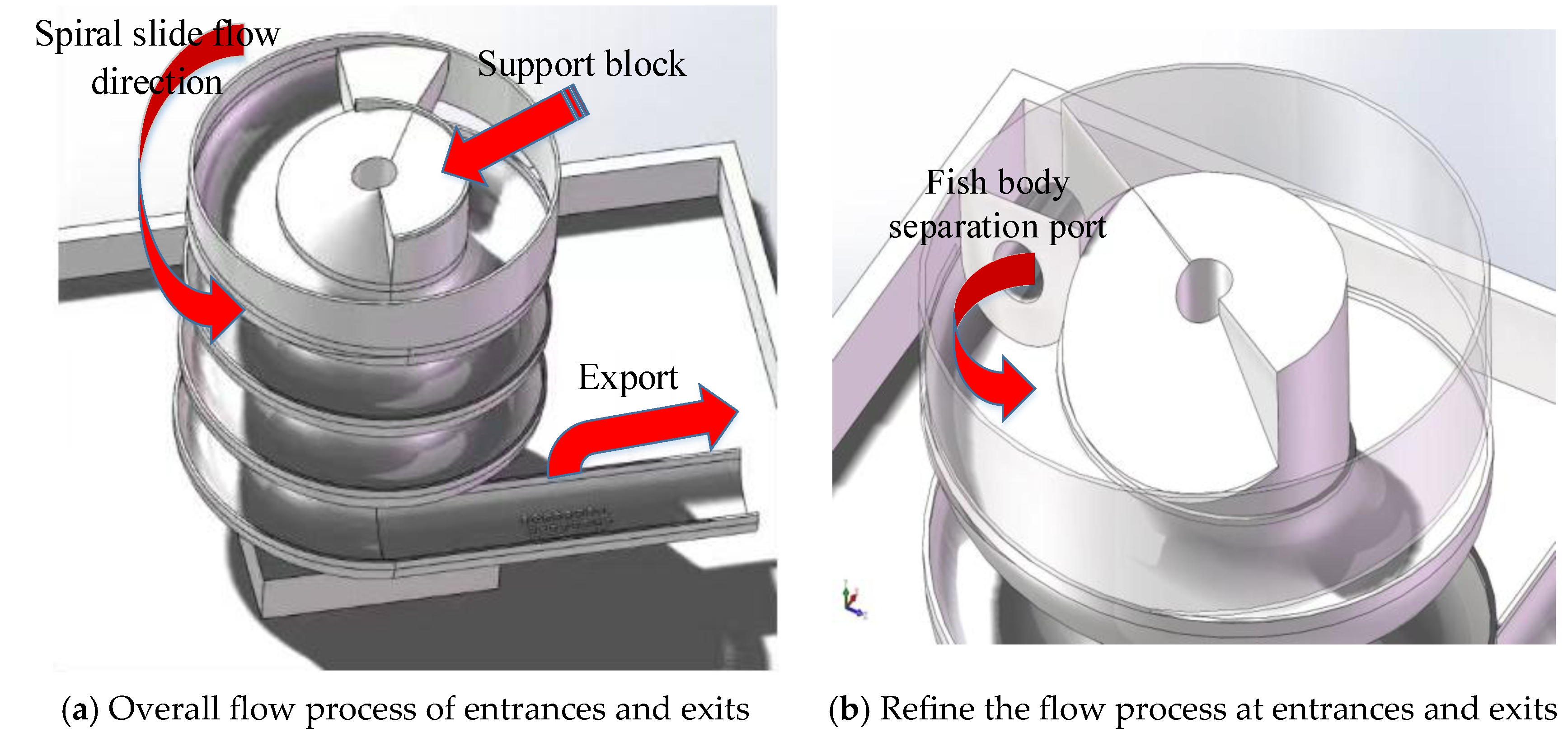
Figure 1 shows the overall schematic of the spiral device. The spiral device is driven by the fish’s own weight and water flow, requiring no external power. Fish enter the feeding inlet at intervals through the water film delivery pipe and slide along the spiral chute under the influence of gravity and water flow. During sliding, the fish are affected by the components of gravity, water resistance, and friction, gradually achieving spacing separation. The main structural parameters of the device are shown in
Table 1.
2.2. Dynamics Model of Fish Body in a Spiral Channel
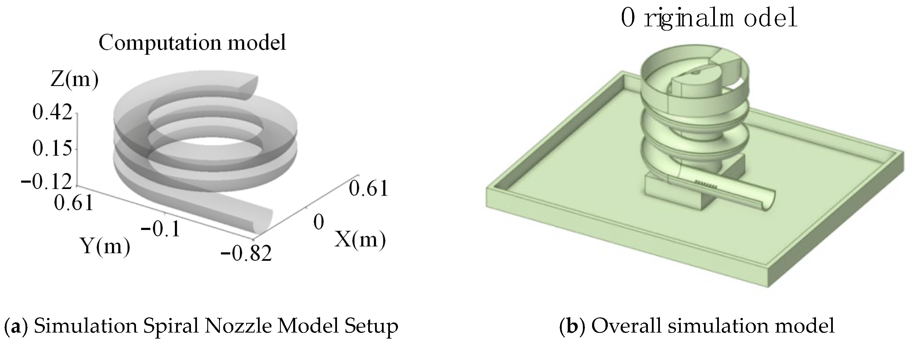
This paper constructs a multi-stage dynamic model of fish sliding in a spiral flume in the MATLAB 2024 environment. In the initial stage, a simplified model driven by gravity and water flow is used to quantitatively analyze the impact of different modeling assumptions on sliding results. Subsequently, 3D modeling is performed using SolidWorks 2024, and analyses are conducted using Ansys Rocky to verify sorting effects.
There is a flow-splitting phenomenon for fish inside the spiral flume, and the flow-splitting ratio is an important factor affecting its performance. To quantitatively analyze the effect of flow splitting, the flow-splitting ratio is introduced. The bypass flow-splitting ratio is defined as the ratio of bypass flow to inlet flow, while the bottom flow fish ratio is defined as the ratio of fish in the bottom flow to fish in the inlet flow [
23].
The sum of the bypass diversion ratio and the baseflow diversion ratio is the total diversion ratio, as defined in Equation (3) [
23].
The proportion of bypass flow in the total flow is denoted as
BF, as shown in Equation (4). This parameter is needed for subsequent studies of related operating conditions [
23].
In the formula: Sb—Bypass shunt ratio (%);
Qb—Bypass shunt volumetric flow rate (m3/s);
Qr—Inlet fish volume flow (m3/s);
Su—Base Flow to Total Flow Ratio (%);
Qu—Baseflow and diversion volumetric flow rate (m3/s);
S—Total shunt ratio (%);
Qo—Overflow Air Volume Flow (m3/s);
BF—The proportion of bypass shunt ratio in the total shunt ratio (%).
The fish body separation efficiency in a spiral chute is assessed. In fish, the focus is on the quality of the captured fish, and traditional overall separation efficiency or fractional efficiency should be used [
23].
In addition, to measure the proportion of fish separated into bypass flow and base flow, the parameter Bs is introduced for evaluation, which is defined as shown in Equation (8) [
23]:
In the formula: E—Total Separation Efficiency (%);
mf—Inlet Fish Mass Flow (mg/s);
mu—Fish mass flow in baseflow diversion (mg/s);
mb—Fish mass flow in bypass diversion (mg/s);
mo—Overflow Orifice Fish Mass Flow Rate (mg/s);
cf—Inlet Fish Concentration (mg/m3);
co—Fish concentration at the overflow (mg/m3);
Ed—Fish Sorting Efficiency (%);
cfd—Fish concentration with an inlet particle size of d (mg/m3);
cod—Fish concentration with an overflow orifice diameter of d (mg/m3);
E’—Converted Separation Efficiency (%);
Bs—Proportion of fish separated by bypass diversion (%).
The resultant force acting on the fish’s body can be expressed as:
In the formula, F is the tangential resultant force on the slide, m is the mass of the fish, aw represents the acceleration per unit mass generated by the water flow, Fd is the fluid resistance, and Ff is the friction force on the slope.
Acceleration is defined as follows [
26]:
In the formula: a is the instantaneous acceleration of the fish; g is the acceleration due to gravity; awater is the effective propulsive acceleration provided by the water current; Cd is the drag coefficient; ρ is the density of the water; A is the projected area of the fish body; v is the instantaneous velocity of the fish; μ is the kinetic friction coefficient between the slide surface and the fish; and R is the local radius of curvature of the slide.
2.3. DEM–SPH Coupled Calculation Method
Smoothed Particle Hydrodynamics (SPH) is a method used for numerically simulating the behavior of continuous media, such as fluid dynamics [
32,
33,
34]. The SPH method is a Lagrangian mesh-free approach that can effectively account for the interaction between fluids and particles when dealing with problems involving high solid content and free-surface flows [
32,
34]. In this simulation, it will be used to model the movement of a fish’s body in a water layer. In the SPH method, the fluid is represented by a set of irregularly distributed nodes, where the fluid’s physical properties such as mass, density, velocity, position, and pressure are known. These SPH elements serve as interpolation points for integrating the Navier–Stokes equations that control fluid flow.
The SPH solver employs a weakly compressible formulation with an artificial equation of state following the Tait relation; the initial particle spacing was set to Δp = [value] m with a smoothing length ratio h/Δp = 1.2, consistent with recommendations for free-surface channel flows. Fish-body particles were modelled using the Hertz-Mindlin no-slip contact law; the normal stiffness, tangential stiffness, and coefficient of restitution were assigned values calibrated from available material property data for fish tissue analogues. Fluid–particle coupling was implemented through a locally volume-averaged drag force scheme with bidirectional momentum exchange [
35]; the drag coefficient was computed from the Schiller-Naumann correlation as a function of the local particle Reynolds number. Convergence was assessed by monitoring the RMS residuals of velocity and pressure fields across successive time steps, with a threshold of 1 × 10
−4 adopted as the stopping criterion.
To ensure numerical transparency and reproducibility, the DEM-SPH coupling model was implemented using its built-in SPH solver. The SPH particle size was set to 2 mm, with a smoothing length of 1.2 times the particle spacing to maintain stability. The fish body was modeled as a rigid clump of spheres using the Hertz-Mindlin contact model with a rolling friction coefficient of 0.01. Fluid–particle coupling was governed by a semi-analytical drag model with a coupling sub-stepping ratio of 10. Convergence was achieved when residuals fell below 10−4 for continuity and momentum equations.
DEM–SPH coupling is a two-way coupling approach that does not rely on a closed model when simulating fluid–particle interactions [
32,
33,
34,
35]. Instead, this method handles momentum transfer between fluid and particles through an analytically coupled approach. Therefore, the scale of SPH units should be at least several times smaller than the particles so that fluid flow around solid particles can be explicitly resolved [
32,
33]. As shown in
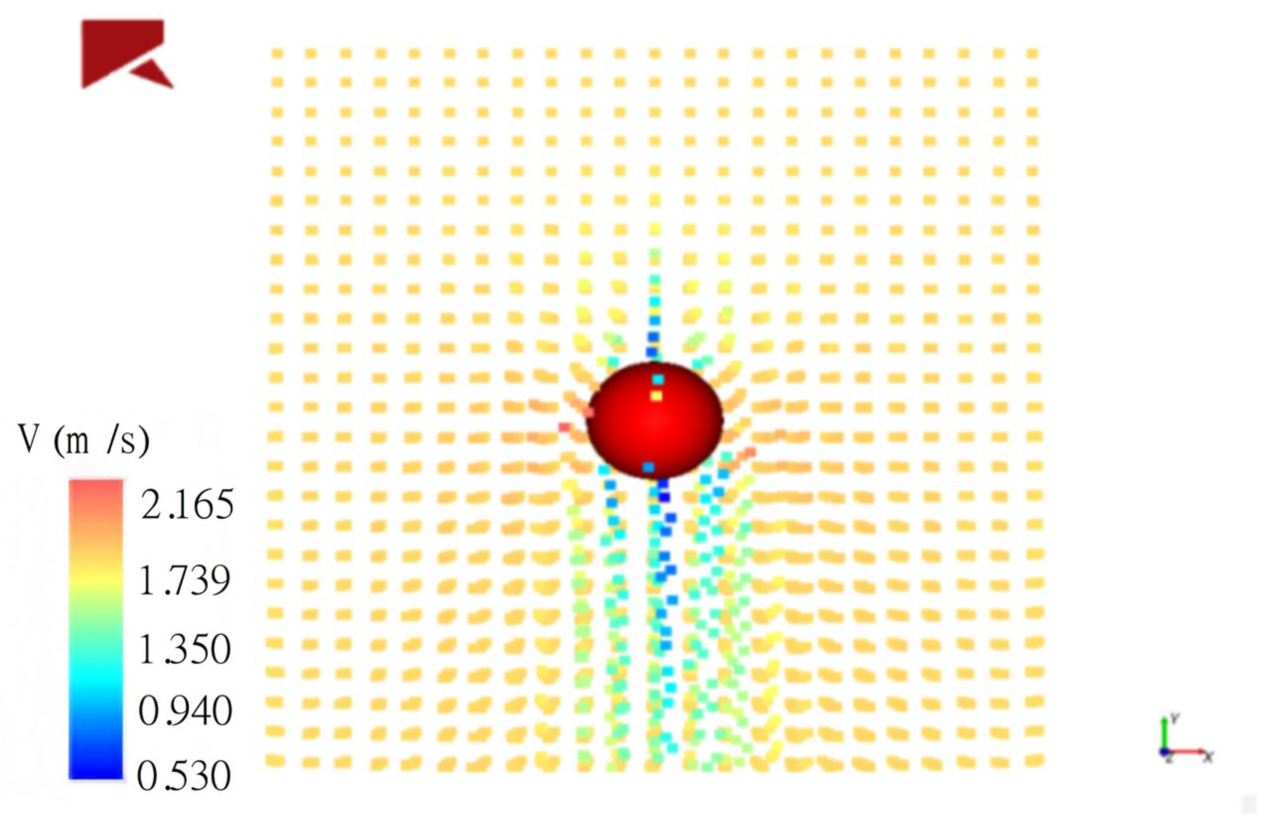
Figure 2, SPH units are colored according to absolute velocity and interact with the particles. In order to overcome the limitation of passive particle modeling, a simplified behavior control framework is introduced into the DEM-SPH coupling model. Every fish agent is equipped with a rules-based reaction to local flow conditions and proximity to other fish. In particular, when the local fluid speed exceeds a certain threshold, the fish can actively adjust its direction to maintain its stability; when the distance to the adjacent fish is less than a safe margin, a side-to-side maneuver is triggered. This is done by modifying the speed vector and orientation of the fish at every DEM time step based on local SPH-derived flow data. Although this approach does not fully replicate real fish locomotion, it provides a more realistic representation of fish–fish and fish–flow interactions than purely passive models, and improves the accuracy of predicted spacing and collision rates.
In numerical simulations, the integral interpolation form of
A(
ra) can be expressed as a summation over its neighboring SPH elements
b.
where
mb is the mass of the neighboring SPH element
b;
ρb is the density of the neighboring SPH element
b;
rb is the position of SPH element
b; and
Ab is the value of property
A at position
rb. In three-dimensional SPH smoothed particle hydrodynamics calculations, the term
mb/
ρb can be regarded as the volume associated with each SPH element, used to reflect the particle discretization characteristics of the fluid domain. The local fluid properties are determined collectively by the contributions of neighboring particles within the computational domain. The spatial gradient of the physical quantity A can be obtained by taking the partial derivative of the kernel function with respect to position
ra, and its expression is:
In the formula, ∇aWab represents the gradient of the kernel function W(ra − rb, h) with respect to the position of particle a. This form provides a numerical approximation of spatial derivatives without a mesh, offering a theoretical foundation for computing pressure gradients, viscous forces, and fluid stress terms in the SPH method.
4. Conclusions
This paper presents a passive fish pre-sorting device utilizing a spiral chute structure, designed to mitigate issues such as stacking, collisions, and stress responses during aquaculture grading. Through the construction of a dynamic model and the application of DEM-SPH coupled numerical simulations, the motion behavior and separation mechanism of fish within the spiral channel were analyzed.
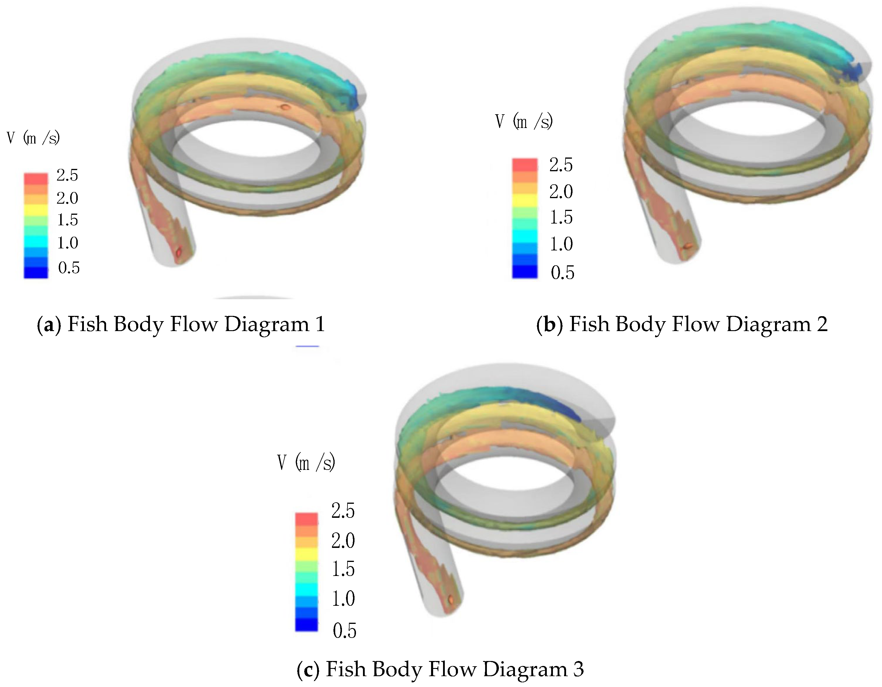
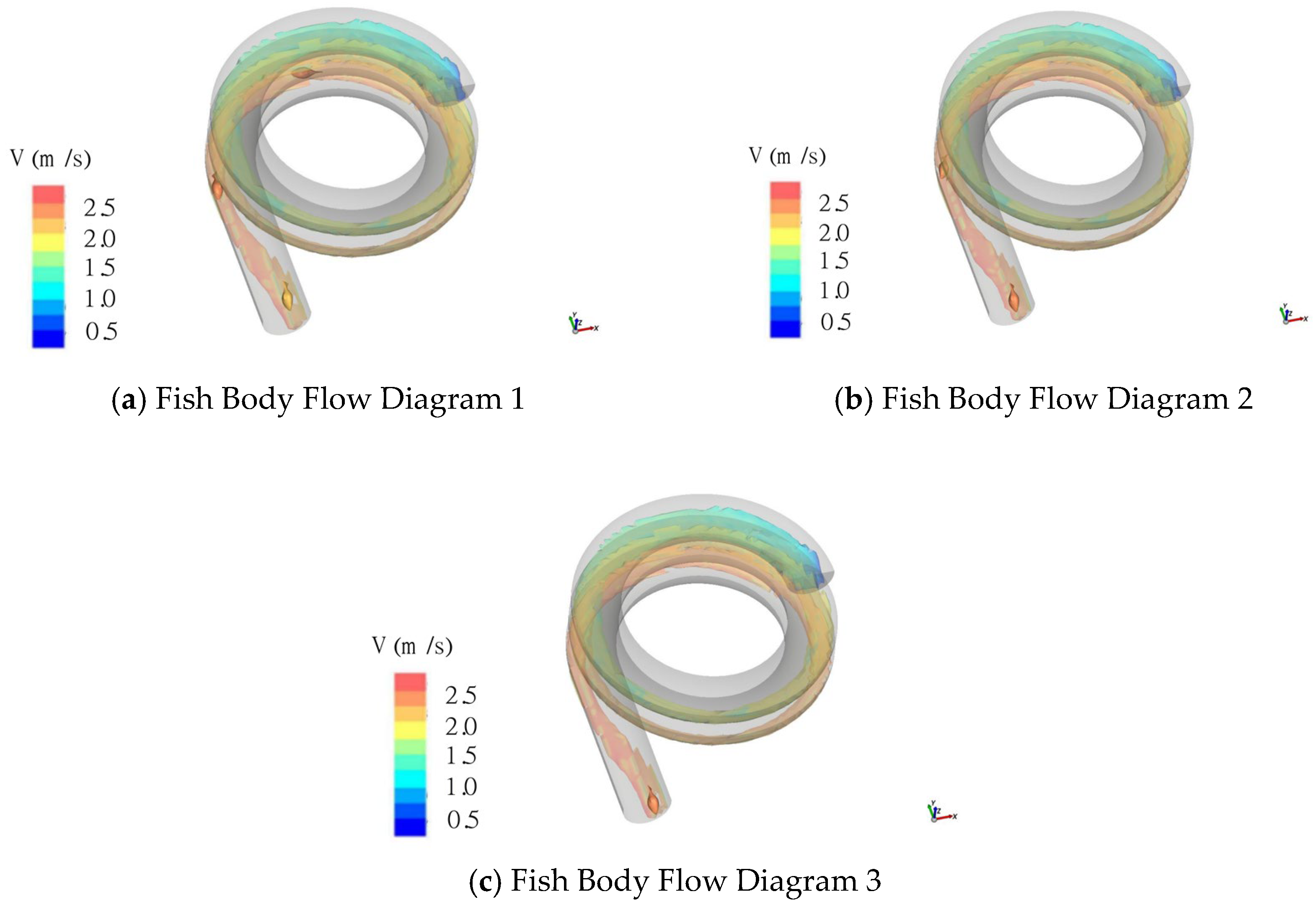
(1) The simulation results indicate that the device enables automatic spacing adjustment and orderly output using only the fish’s own weight and water flow. The DEM-SPH coupling method effectively reproduces the fluid–fish interaction, illustrating a self-sorting process influenced by fluid inertia and vortex dynamics. These findings support the theoretical feasibility of the proposed design.
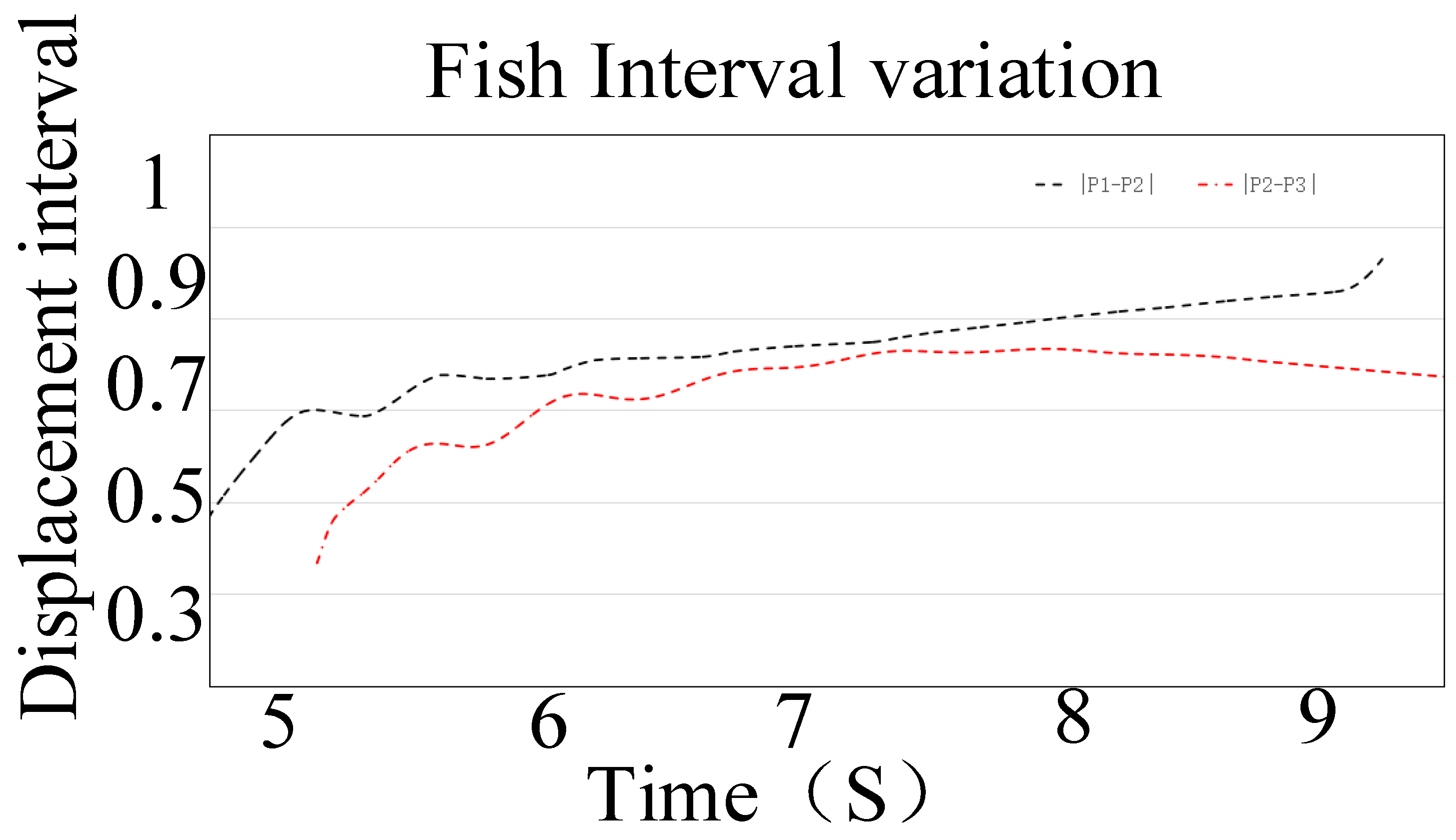
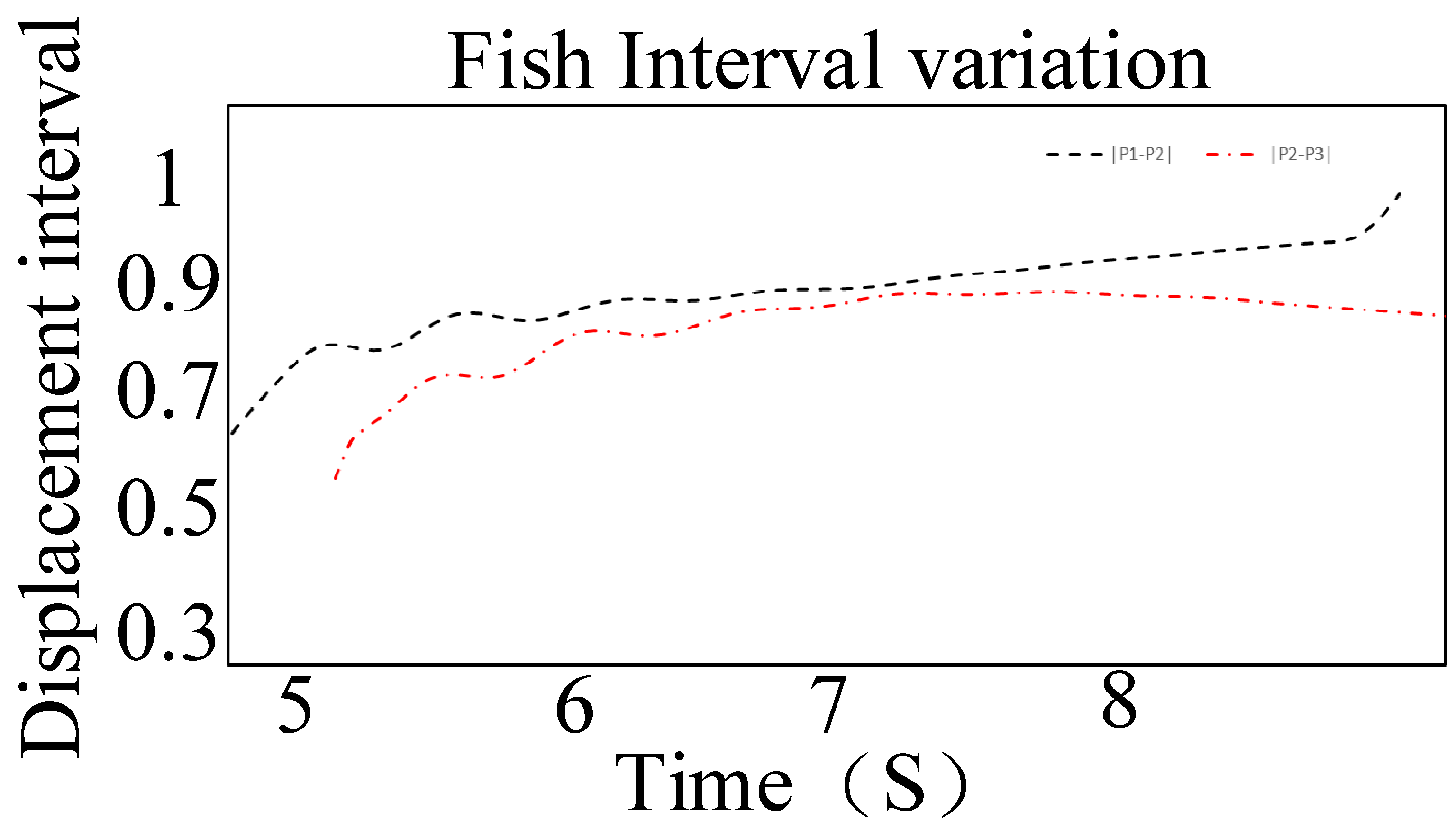
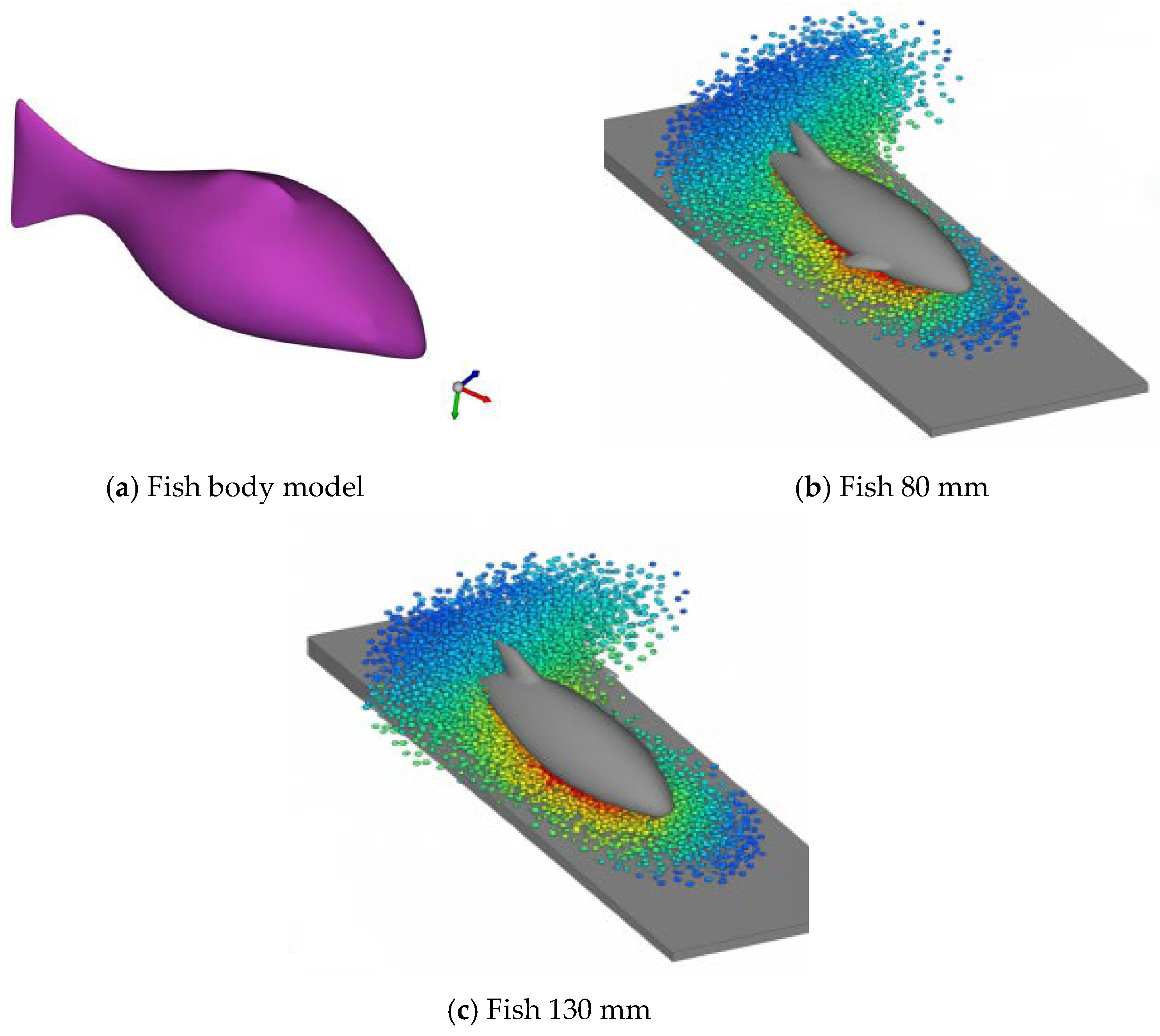
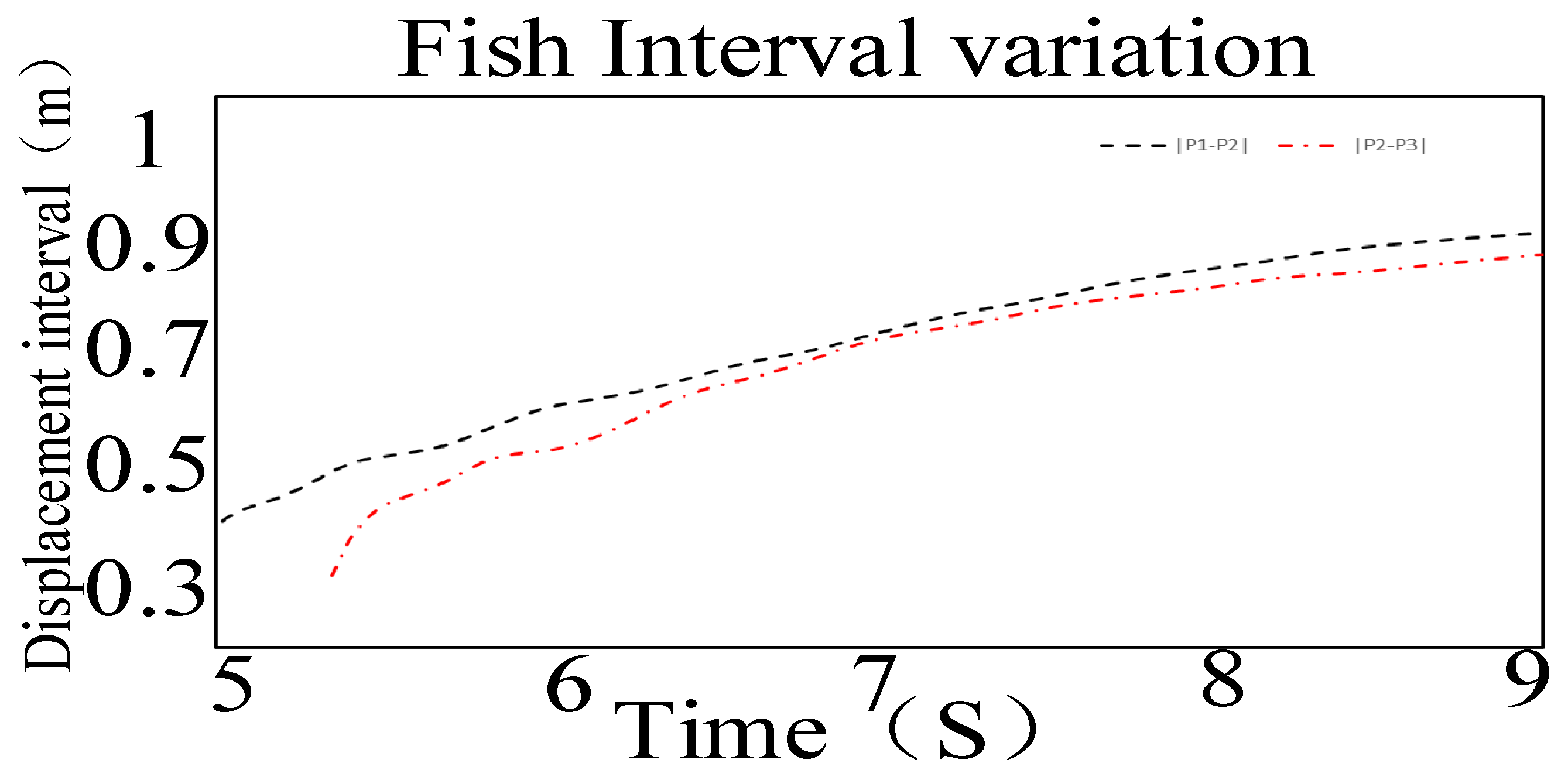
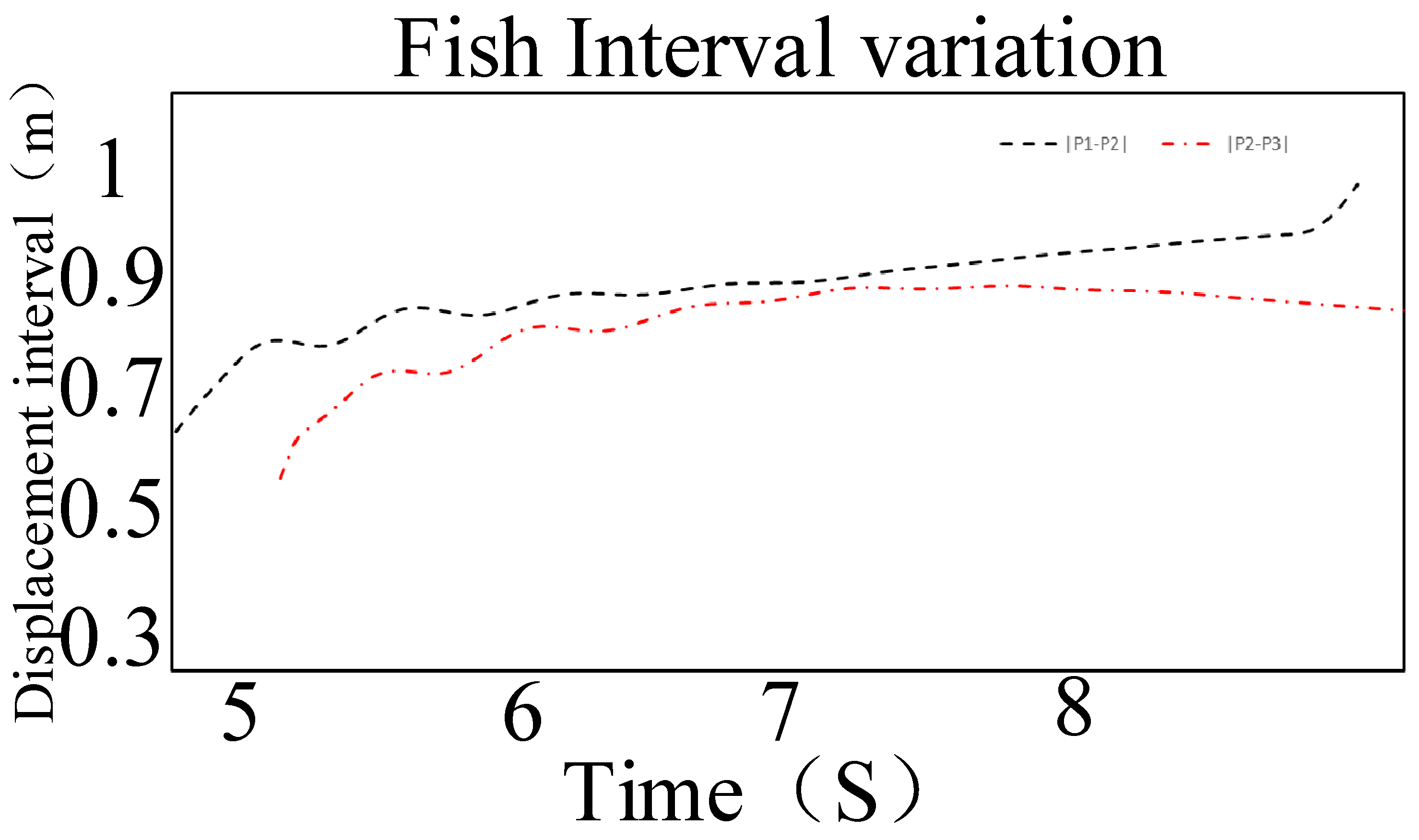
(2) Parametric simulations reveal that both fish length and water layer thickness affect sorting performance. Models representing 80 mm and 130 mm fish both exhibited progressive spacing along the chute, with the 130 mm model demonstrating more consistent behavior. Under a thinner water layer (1 cm), spacing increased rapidly but with greater fluctuation, whereas a thicker layer (5 cm) yielded smoother progression. Based on these observations, a water layer thickness of 3–5 cm is suggested as a compromise between sorting stability and fluid driving efficiency.
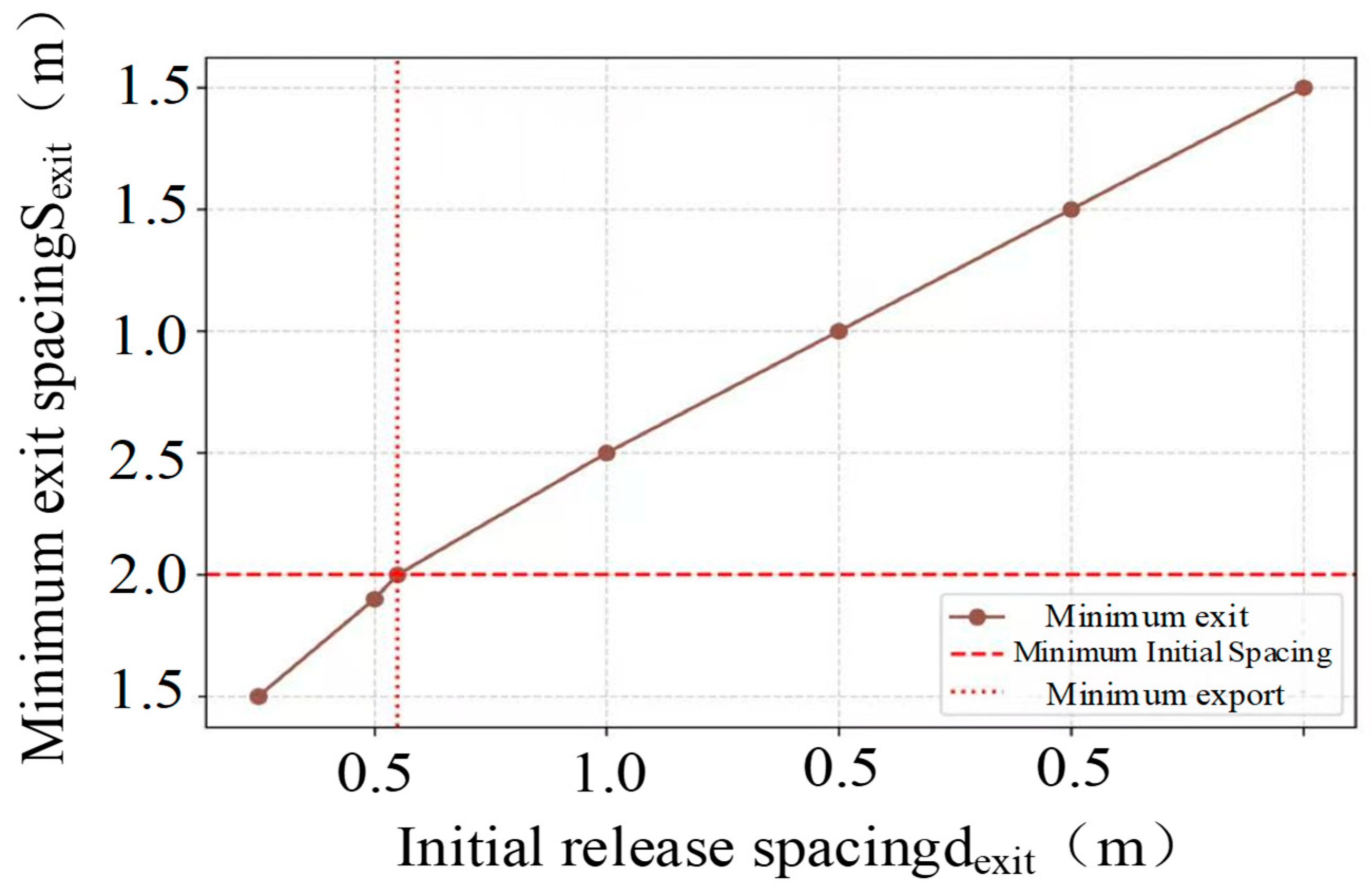
(3) Dynamic model validation and initial spacing analysis show that a minimum release spacing of 0.11 m is required to maintain an outlet spacing above 0.10 m, a threshold considered adequate for downstream visual recognition. For engineering applications, a release spacing of no less than 0.13 m is recommended to account for operational variability.
Compared with traditional powered graders, the proposed spiral chute device achieves a similar or higher grading efficiency at zero energy consumption and a lower predicted number of fish injuries, providing a more sustainable and more fish-friendly alternative to intensive aquaculture.
The present study relies on numerical simulation as the primary investigative tool, which warrants a candid discussion of the associated assumptions and boundaries of applicability. The DEM-SPH coupled model was constructed based on established constitutive laws for granular contact mechanics and weakly compressible smoothed-particle hydrodynamics, both of which have been independently validated in prior literature for analogous fish–fluid interaction problems and granular-flow channel systems. The particle resolution, smoothing length, and coupling parameters adopted here fall within ranges reported to yield convergent and physically representative results in comparable studies. While direct one-to-one comparison with live-fish experiments was not conducted in this work, the dynamic separation behavior predicted by the model—wherein larger individuals migrate preferentially toward the outer channel wall under combined centrifugal and hydrodynamic loading—is mechanistically consistent with field observations reported in passive sorting devices using inclined and helical channel geometries.
The absence of purpose-built physical experiments represents a limitation that the authors acknowledge. To partially mitigate this gap, a sensitivity analysis was performed across the key model parameters, including particle stiffness, fluid viscosity representation, and inlet flow velocity, confirming that the predicted size-separation trends remain stable across a realistic parameter range rather than being artefacts of a particular parameter set. The outlet separation distances and trajectory envelopes extracted from the simulations were further assessed against published empirical data on fish locomotion kinematics and drag characteristics available in the open literature, and the deviations remained within acceptable engineering bounds. These cross-checks, while not a substitute for controlled physical validation, collectively support the mechanistic credibility of the simulation framework.
Future work should prioritize small-scale physical model experiments using fish analogues of known geometry and density to provide direct quantitative validation of the simulated separation efficiency and stress distribution fields. A transparent reporting of percentage deviations between simulated and measured outlet spacing, trajectory curvature, and contact force magnitude will substantially strengthen the scientific standing of the device concept. The authors intend to pursue this validation pathway and report the results in a subsequent contribution.



 ,
,