Article

Design and Experiment of a Hard-Shell Clam Harvester

1
Key Laboratory of Smart Breeding (Co-Construction by Ministry and Province), Ministry of Agriculture and Rural Affairs, Tianjin Agricultural University, Tianjin 300392, China
2
College of Engineering and Technology, Tianjin Agricultural University, Tianjin 300392, China
3
College of Basic Science, Tianjin Agricultural University, Tianjin 300392, China
4
Tianjin Haisheng Aquaculture Co., Ltd., Tianjin 300272, China
5
Institute of Oceanology, Chinese Academy of Sciences, Qingdao 266000, China
*
Author to whom correspondence should be addressed.
These authors contributed equally to this work.
Fishes 2025, 10(5), 217; https://doi.org/10.3390/fishes10050217
Submission received: 11 March 2025 / Revised: 30 April 2025 / Accepted: 4 May 2025 / Published: 7 May 2025
(This article belongs to the Section Fishery Facilities, Equipment, and Information Technology)

Abstract

Hard-shell clams are highly valued for their nutritional and economic benefits, leading to an increase in their aquaculture scale. Harvesting these clams manually leads to low efficiency and high labor intensity; thus, a new type of hard-shell clam harvester has been designed to overcome this challenge. Based on biological characteristics and sediment properties of hard-shell clams, a 3D model of the harvester has been created utilizing SolidWorks software (version 2022), which has a working length of 980 mm, an excavation depth range from 0~12 mm, and an angle of entry of 22 degrees. To optimize the efficiency of the machine, a Discrete Element Method (DEM) simulation trial was conducted through a three-factor three-level experiment using EDEM software. Results indicated an optimal harvest efficiency of 91.17% with the machine achieving a running speed of 0.526 m/s, roller speed of 4.772 r/min, and excavation depth of 73.067 mm. Field experiments verified the feasibility of the harvester, demonstrating high accuracy when compared to simulation results.
Key Contribution: This study takes the buried shell clam as the research object, the cultivation bottom material and the biological characteristics of the hard-shell clam are integrated, the development of the hard-shell clam harvesting mechanism is carried out, and a new hard-shell clam harvesting machine (hereafter referred to as clam harvester) is designed to provide ideas for the design of buried shellfish harvesting equipment. The discrete element model of soil and clams was constructed for simulation tests, and its feasibility was verified by a simulation test and field test.

1. Introduction

Coastal tidal flats cover approximately 10 million hectares in China, representing a valuable land resource, and an ideal place for expanding the culture of bivalve mollusks [1]. The hard-shell clam (Mercenaria mercenaria), also referred to as the cherrystone or northern quahog, is one of the primary economic bivalve mollusks commonly found in shallow waters and tidal flats along the Atlantic coast of the United States. The species was first introduced for cultivation in China in 1997 by academicians (e.g., Zhang Fusui [2]). The main method of harvesting bivalve mollusks on tidal flats in China initially relied on manual capture, which involved the insertion of specialized tools such as iron rakes or iron plows into the surface of the tidal flats to a certain depth. The tools were then tilted at a certain angle and pulled back until they hit the clam, which would then be flipped out for collection. Manual capture had several drawbacks, including low harvest efficiency and intense labor, resulting in high costs. As China’s bivalve aquaculture expanded, manual capture became no longer practical, and the focus shifted to mechanical capture methods [3].
The hard-shell clam harvester was originally developed in the 1940s, followed by the development of numerous variants in subsequent years, including towing and harrow harvesters [4], rotary gear harvesters [5], paddle harvesters [6], hydraulic harvesters [7], suction harvesters [8], and vibrating harvesters [4]. In 1974, the Canadians Caddy and Medcof compared the efficiency of Chain-net trawl capture devices and hydraulic jetting capture devices in harvesting the Atlantic Ocean quahog. It was found that the former had lower efficiency and higher damage rates when harvesting Arctic clams in the culture sediment containing a lot of sand [9]. In 1981, Weng Zhengtong [10] and others from the Wuxi Institute of Agricultural Machinery designed a YXF-4 screw suction machine with centrifugal sludge pump. The suction cup was first sunk to the bottom and then the pump was opened. Seabed shellfish, sediment, and water was sent to the ship with the suction of the pump, and the separation of shellfish and mud and sand was completed through the separation device. This operation resulted in increased turbidity of the water; on the other hand, mortality of the collected shellfish returned to the sea bottom was high [11,12,13,14]. In 1998, Japanese scholar Shinsaro Yamazaki et al. [15] studied the effect of hauling speed on clam mortality by using trawl capture devices, and the results showed that when the trawl hauling speed of the capture was <100 m/h, the clam damage rate was small. In 2018, Zhang Wancai et al. [16] from the Fujian Agriculture and Forestry University designed a multifunctional tidal flats harvesting vehicle, which collected shellfish by using a digging shovel, and transferred the shellfish to a shell bucket by using a suction pump to complete the collection. In 2021, Lu Jian et al. [17] developed a self-propelled tidal flats shellfish harvester. The harvester is composed of a tractor, shovel plate, conveyor chain, cleaning roller, vibrating screen, collection frame, etc. After the shovel plate picks up the shellfish and sediment, they are transported backward through the conveying device while the cleaning roller cleans the surface and sediment of the shellfish, and then the vibrating screen cleans the sediment twice before falling into the collection box.
In view of the problems of low efficiency and high cost of shellfish harvesting, a new type of shellfish harvesting device was developed in this paper. In order to verify its reliability and authenticity, simulation analysis was carried out.

2. Overall Structure and Operating Principle of the Clam Harvesting Machine

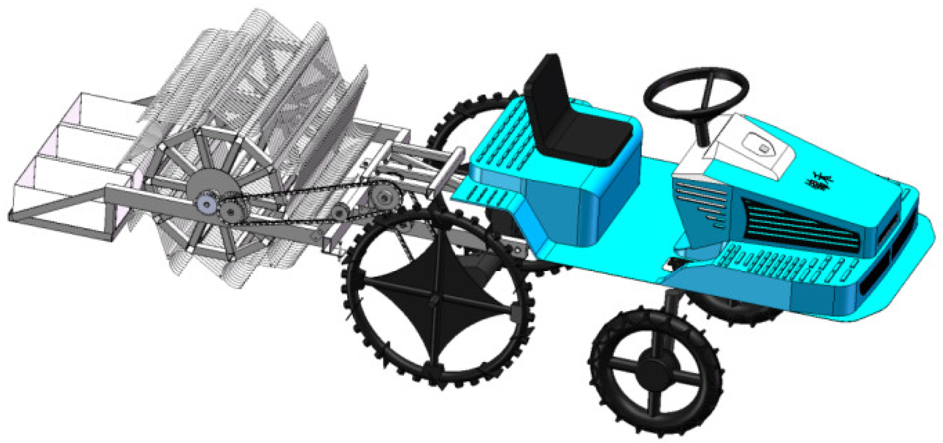
2.1. Overall Structure

The model of the whole clam harvester is shown in Figure 1. It is composed of a tractor and a digging system. The overall structure of the digging system is shown in Figure 2. It is primarily composed of a frame, a fixed rack, a first chain wheel drive, a second chain wheel drive, tines, a digging mechanism support, a collection box, and a collection box fixing rack. The complete specifications of the clam harvester are listed in Table 1. The tractor used is the Jinhe 2ZG-8KZ rice transplanter, which adopts a large-diameter flip-plate anti-sinking wheel and can effectively prevent sinking. It is suitable for hard-shell clam cultivation sediment [18]. The digging system needs to be fixed onto the tractor by a flat-headed pinhole clevis pin, and then the fixed rack is welded to the rear of the tractor.

2.2. Operating Principle

During operation, the clam harvester uses the rice transplanter as its tractor, and can adjust the position of the harvesting machine through a tensioner to change the digging depth. The power is transmitted from the tractor to the fixed rack, and then from the fixed rack to the rollers, driving them to rotate and harvest the hard-shell clam. When the tines on the roller reach the bottom, it enters the hard-shell clam cultivation sediment. As the roller rotates, it brings the excavated clams and sediment to the collection device. When it rotates to the back of the device, the hard-shell clam slides down the back of the tines and falls into the collection box.

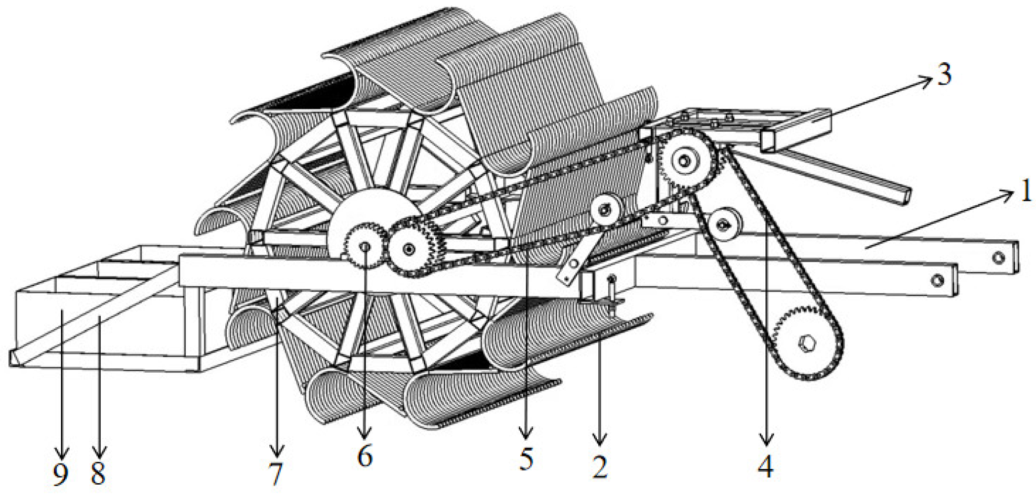
3. Composition and Key Components Design of the Digging Mechanism

The function of the digging mechanism is to excavate the mixture of hard-shell clams and cultivation sediment and convey it to the collection box. It is one of the key components of the entire harvesting machine, as shape and size, among other factors, directly affect the digging performance of the clam harvester [19].

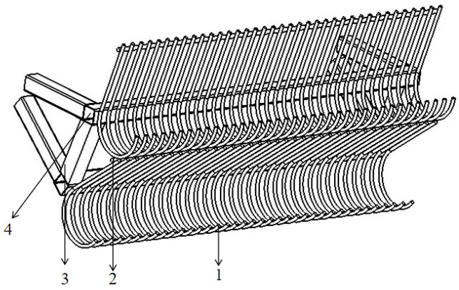
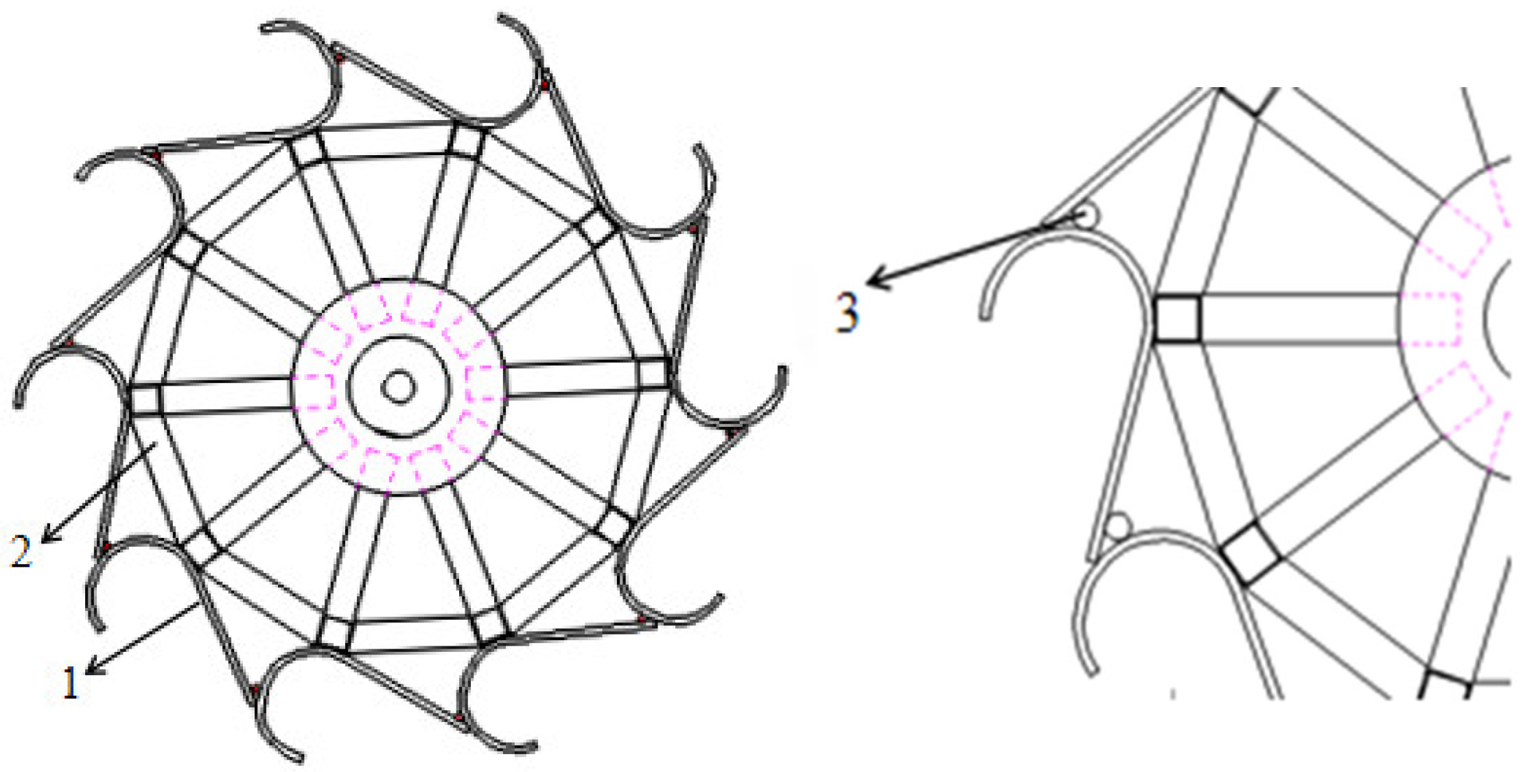
3.1. Composition of the Tines’ Assembly

The clam harvester’s tines’ assembly is mainly composed of tines, a fixed shaft, a crossbar, and surrounding bars, as shown in Figure 3.

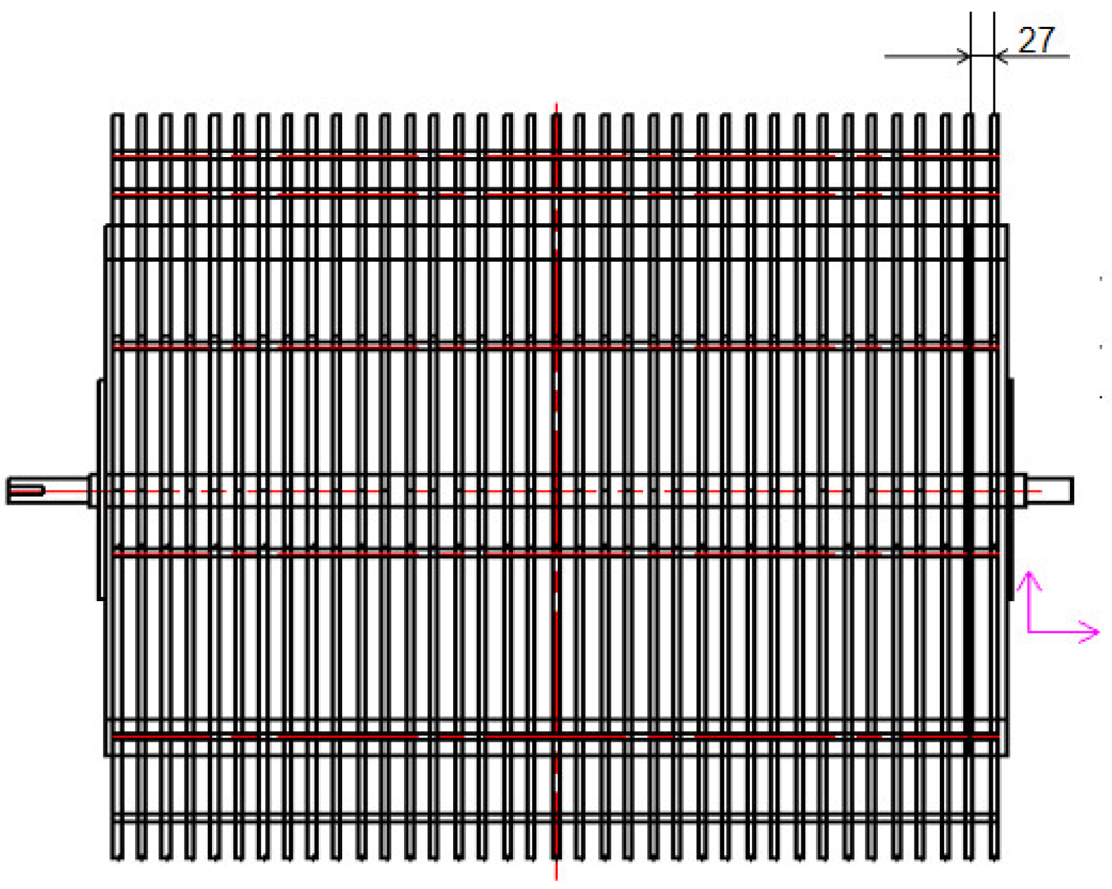
3.2. Design of the Tines

When digging hard-shell clams, the digging depth affects the ability to fully remove all clams. Moreover, contact between the tines and the cultivation sediment creates additional resistance. Therefore, it is necessary to control the angle and depth of the tines to minimize resistance. The arrangement width of the tines affects the selection of adult and juvenile clams. Therefore, the basic parameters that need to be determined for the design of the tines include the excavation depth h, the angle of penetration θ, and the arrangement width w [20].

3.2.1. Design of the Excavation Depth

The excavation depth for the digging tines was designed based on the burial depth of hard-shell clams in the cultivation sediment. To obtain the burial depth of hard-shell clams in the cultivation sediment, in the season of hard-shell clam harvesting, four randomly selected sites were sampled in the cultivation area to dig hard-shell clams, and the burial depth of hard-shell clams was measured. The burial depth of hard-shell clams in the sediment was found to be in the range of 0~60 mm. As the digging depth is directly proportional to the digging resistance, the greater the excavation depth, the greater the digging resistance, so when designing the clam harvester, the digging depth should not only ensure that all hard-shell clams are harvested, but also minimize digging resistance. Therefore, the radius of the tines was set to 67 mm, and the digging depth was set to 0~120 mm.

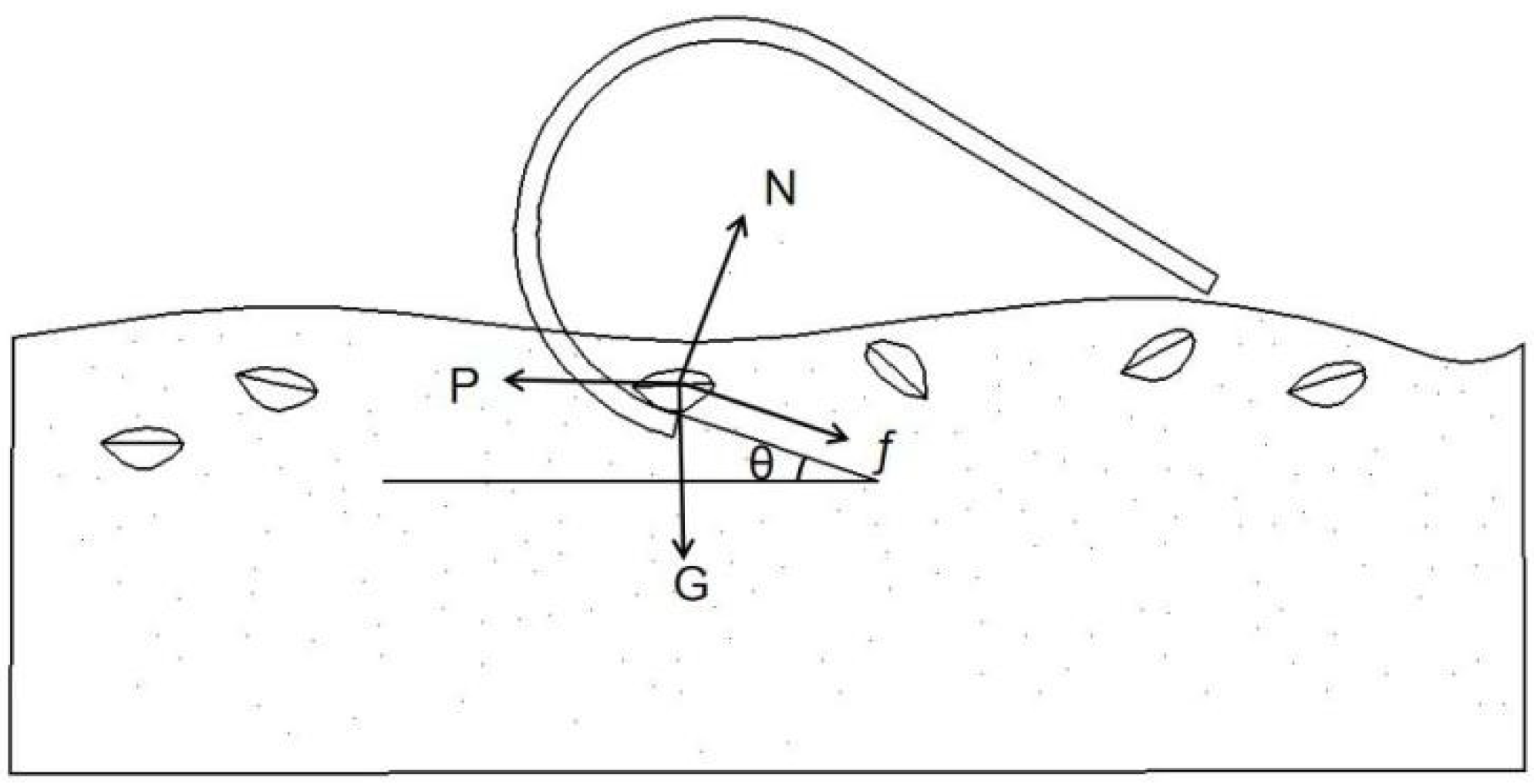
3.2.2. Design of the Penetration Angle for the Tines

The angle at which the tines penetrated the sediment affected the penetration performance of the tines, as well as the movement speed of the hard-shell clams and cultivation sediment on the tines, and the amount of the digging resistance. When the angle of the tines face was small, the digging resistance was small and the movement speed of the hard-shell clam and sediment on the tines was fast, but the penetration performance was poor. As the angle increased, the penetration performance enhances, but the digging resistance increases, and the movement speed of the hard-shell clam and sediment on the tines slows down, which can lead to soil clogging problems [21]. The stress analysis diagram of the tines is shown in Figure 4 [22].
In Figure 4, G represents the weight of the hard-shell clam and soil; P is the force required to dig up the clams and soil along the tines’ face; N is the support force of the tines on the hard-shell clam and soil; f is the frictional force between the soil and the tines, and θ is the angle of penetration of the tines. The equations based on the force diagram of the tines are:
P c o s θ f G s i n θ = 0
N G c o s θ P s i n θ = 0
The frictional force experienced by the soil and hard-shell clam is:
f = μ N .
In the equation, μ represents the coefficient of friction. Derivation of the formula is:
θ = a r c t a n P μ G μ P + G .
According to the actual situation, the inclination angle of the shovel tip of the tine is generally greater than 20 degrees and less than 30 degrees [22]. When the angle is greater than 20 degrees and less than 30 degrees, the resistance increases with the increase of the angle, but the growth value is relatively small. When the inclination angle of the tines is greater than 30 degrees, the digging resistance sharply increases with the increase of the inclination angle. Therefore, the angle of penetration for the tines of this device was set at 22 degrees. The left view of the hooked rotor is shown in Figure 5, which is surrounded by 10 bars to form a decagon. The tines are arranged counterclockwise outside the bars, and each tine is fixed to the other by a fixed shaft, so that every angle of penetration for the tines is 22 degrees when the hooked rotor rotates.

3.2.3. Design of Tines Arrangement Width

When harvesting hard-shell clams, it was crucial to collect the mature clams while releasing their offspring back into the culture sediment for sustainable development. The arrangement of the tines’ width was influenced by the size of the hard-shell clam. When the arrangement width of the tines was too narrow, it could affect the selection of mature and juvenile clams. Therefore, it was necessary to measure the triaxial dimensions (as shown in Figure 6) of adult shell and juvenile shell [23]. Taking the hard-shell clam bred by HaiSheng Aquatic Products Breeding Co., Ltd. in Tianjin, China, as the research object, a portion of the hard-shell clams was subjected to triaxial size measurement and their mean values were taken. Figure 7 shows the measuring of triaxial dimensions of hard-shell clams. The measured triaxial dimensions of the hard-shell clam were obtained as shown in Table 2.
By measuring the trilateral dimensions of hard-shell clams, the sizes of mature and juvenile clams was obtained. In order to screen the mature and juvenile clams effectively, the distance between the center axes of adjacent tines was set to 27 mm.
The power transmission path of the hard-shell clam harvesting device originates from the rear wheels of the tractor, passes through the fixed frame, and finally drives the digging mechanism. Given that the rear wheel track width of the tractor is 1400 mm, the operational width of the harvesting device is set to 980 mm to ensure harvesting efficiency. Each row of the digging mechanism consists of 37 tines. Figure 8 illustrates this configuration.

4. Model Construction and Simulation Analysis

4.1. Construction of Discrete Element Model

At present, there is various software for modeling through the discrete element method, among which the software EDEM (software version 2018). EDEM can create a parametric model of solid particles, and can also import the solid model into the EDEM to add particles and set the particle coordinates to fill the particles, so that it can reflect the shape of the actual material to enhance the accuracy of the simulation. A soil–hard-shell clam agglomerates model, which is close to the culture sediment, can be created, supplying the model and theoretical foundation for the experimental analysis of the hard-shell clam digging process [24].

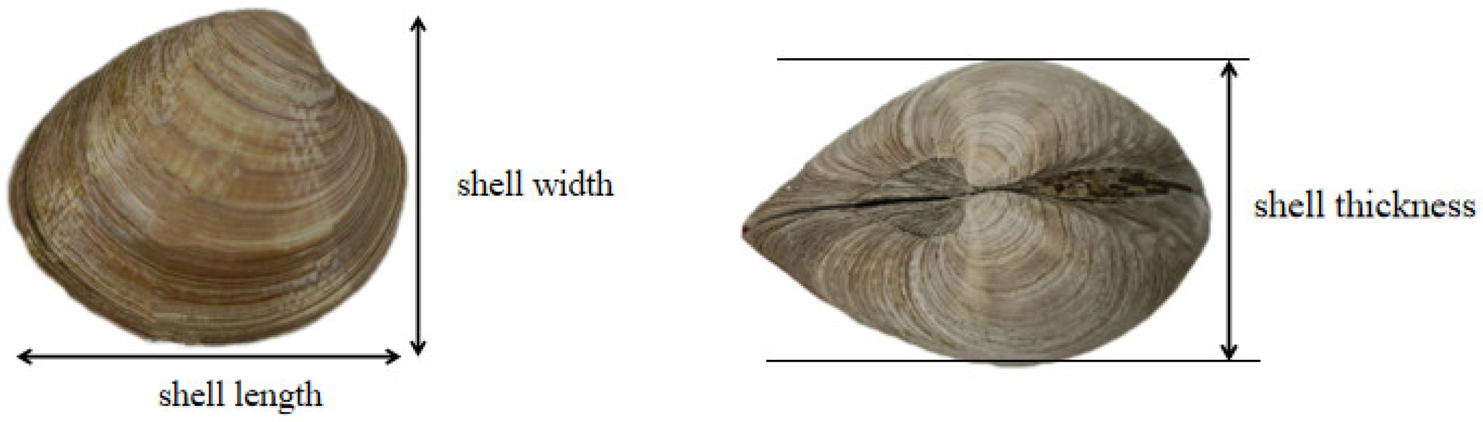
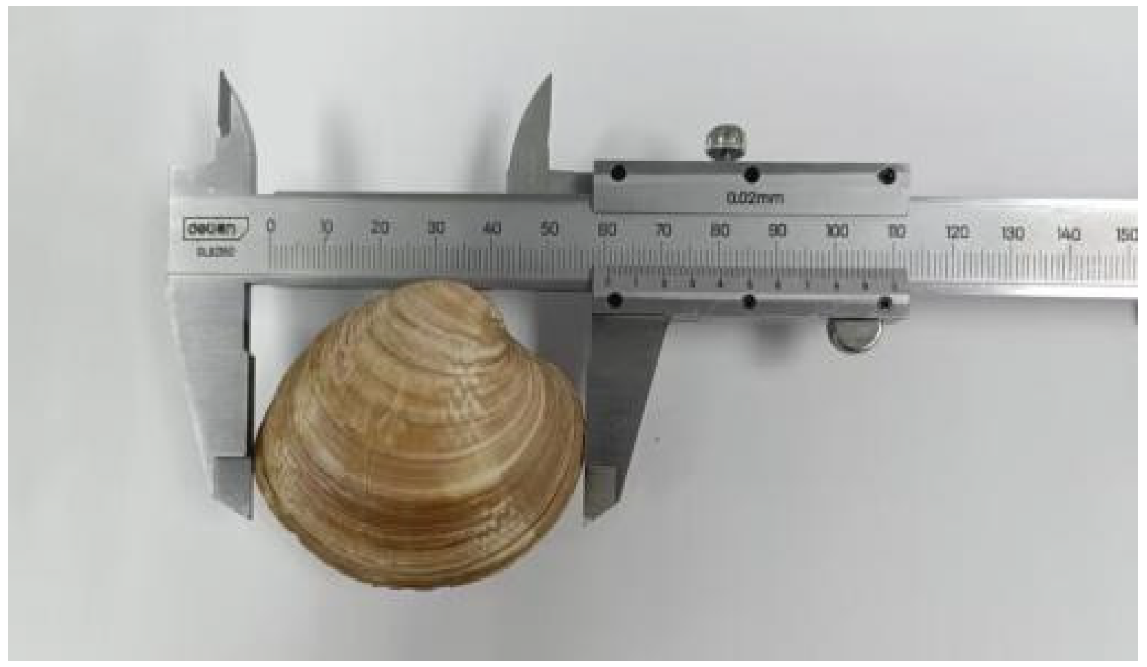
4.1.1. Creation of the Hard-Shell Clam Model

By measuring the trilateral dimensions of the hard-shell clam, the averaged sizes of the mature and juvenile clams were obtained. Using SolidWorks software, a 3D model of the mature and juvenile clams was constructed. The model was saved into an .stl file format and then imported into EDEM for packing the clam template with particles. In packing the particle template, the closer it was to the actual clam component, the better the simulation was. However, that required filling many spheres with an increase in the calculation volume. Thus, the packing procedure is simplified to some degree while maintaining essentially to the realistic structure [25]. The completed clam model after packing is illustrated in Figure 9. In addition, through the measurement and the literature search, the intrinsic parameters attributed to hard-shell clam entities and the contact parameters related to the material were analyzed and summarized, as presented in Table 3.

4.1.2. Soil Model Construction and Contact Model Selection

According to the literature [26], the realistic particle diameter of the breeding sediment of the hard-shell clam has been identified. Because the particle diameter of soil is much smaller, simulating soil particle size based on realistic values would result in a slowed-down operating speed and a longer simulation time. Therefore, the simulated soil particle radius must be set greater than the actual soil particle diameter, with the soil particle radius set to 5 mm [27]. Ref. [26] investigated the virtual calibration experiment for the survival soil of the hard-shell clam to establish the optimum simulation parameters for the soil. The discrete element model parameters for simulations were listed in Table 4 as follows.
Soil consists of solid, liquid, and gas components. The liquid component refers to the water in soil that is in the liquid phase, which mainly refers to the water of various ions and the binding water of the surface of the soil particles and the capillary water, etc., in which the liquid bridge force caused by the capillary water is the bonding force between the soil particles. The bonding between soil particles will significantly affect the work resistance and motion of the particles. Thus, a suitable contact model should be determined for the contact between the soil particles during simulation. The Hertz-Mindlin with JKR model provided by the EDEM software is suitable for models with high-water content and properly reflects the real conditions of soil particles contact, and thus, it was used in this paper to model the contact between soil particles [28].

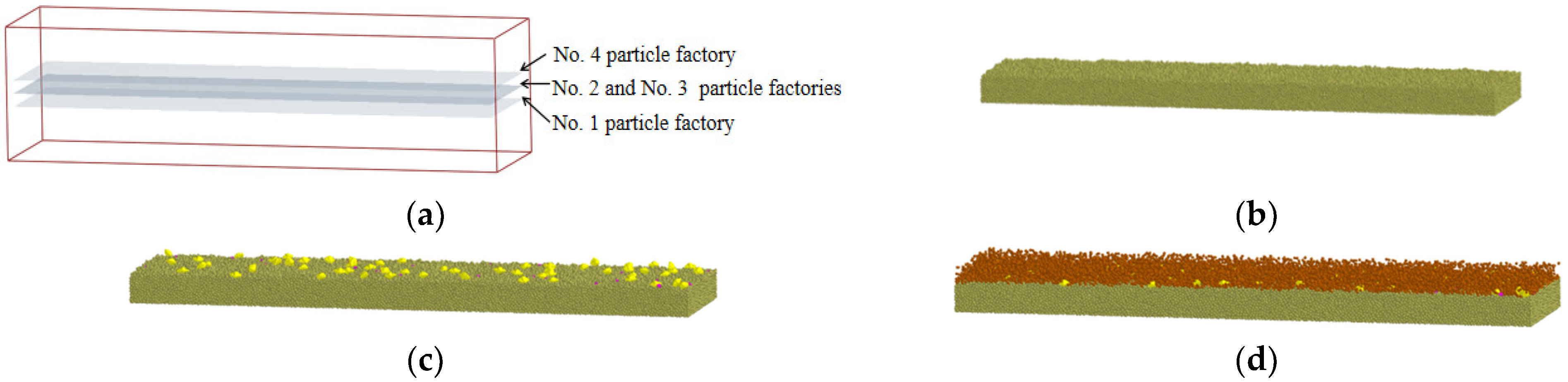
4.1.3. The Construction of the Soil–Hard-Shell Clam Discrete Element Model

Considering the size of the clam harvester and computer hardware configuration, this study adopted the 2000 × 500 × 400 mm soil trough as the simulation boundary. Four particles generation surfaces needed to be established to create the bottom soil, mature clam, juvenile clam, and top soil, respectively, after setting up the virtual soil trough in EDEM. Since the burial depth of the hard-shell clam was considered, the number of generated particles for bottom soil was set to 150,000, with 50 mature hard-shell clams, 25 juvenile clams, and 12,000 top soil particles added, respectively. After setting the specified parameters, the particles would drop freely through the corresponding particle generation surface. When generating the hard-shell clam from a particle generation surface, its initial position was random. The generation process of the soil¬–hard-shell clam discrete element model was as shown in Figure 10. To observe the state of bottom sediment and clam during clam reaping, different colors were assigned to the bottom soil, mature clam, juvenile clam, and top soil, respectively.

4.2. Simulation Experiment Design and Result Analysis

The simulation experiment demonstrates the situation of hard-shell clam harvesting of the harvesting device. Therefore, the harvesting model needs to be imported into EDEM for simulation analysis. However, given that the more complex the model is, the more memory it will consume during operation, the three-dimensional model of the hard-shell clam harvesting device was simplified before being imported into EDEM.

4.2.1. Experiment Objectives

Upon adding the corresponding parameters, the EDEM discrete element analysis software can perform a simulation analysis on the established model. To complete the simulation experiment, it was necessary to reasonably debug the run time and the time step line, and analyze the corresponding data via post-processing module after. The purpose of this simulation experiment is to verify the feasibility of the clam harvester and determine the best experimental parameters, and explore the impact of various factors on the efficiency of hard-shell clam harvesting.

4.2.2. Experiment Scheme Design

According to relevant studies, the digging depth, tines speed, and roller speed significantly affected the harvesting efficiency of hard-shell clam. Therefore, with harvesting efficiency as the performance indicator, and digging depth, tines speed, and roller speed as the factors, a three-factor, three-level experiment was designed (as shown in Table 5).
According to the orthogonal factor level table, the hard-shell clam harvesting discrete element simulation experiment was conducted with the use of the following experimental plan and results (as shown in Table 6). The harvest rate (R%) was selected as the evaluation index for the simulation analysis.

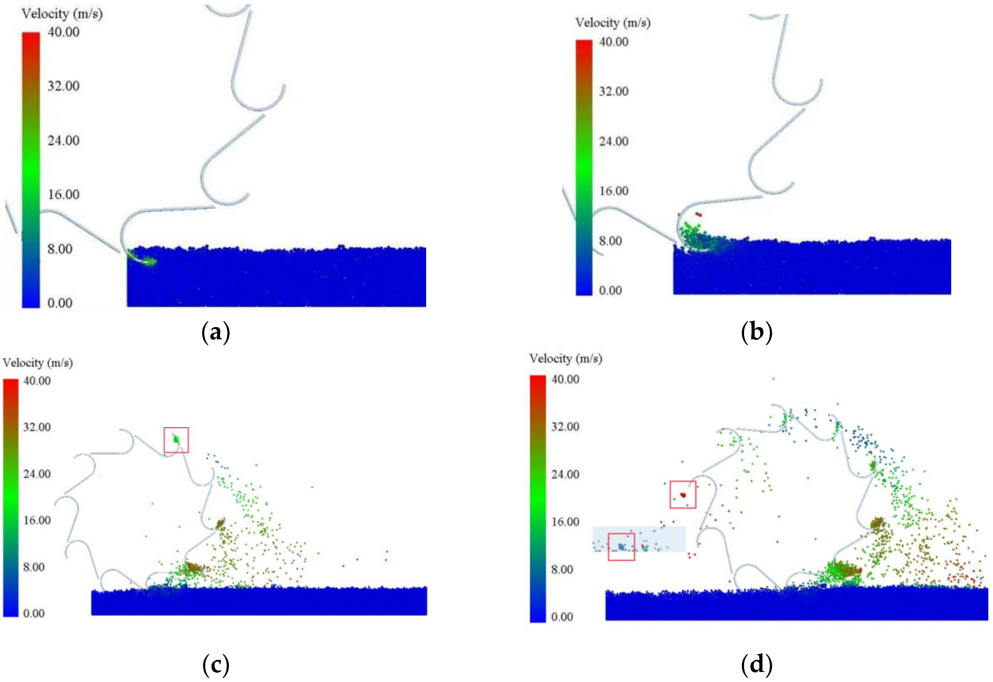
4.2.3. Operation Process Analysis

The simulation process of hard-shell clam harvesting of the harvesting machine is illustrated before and after harvesting in Figure 11. The simulation shows that the clam harvester can transport the hard-shell clam to the collection box, demonstrating its feasibility and verifying the design.
During the harvesting process of the harvesting machine, the trend of soil movement is constantly changing, as shown in Figure 12, in which colors represent the velocity of movement, where red color indicates faster movement than blue color [29]. As shown in the figure, during the early stage of the hard-shell clams and sediment digging by the tines, the digging depth is small, and the resistance keeps reducing; thus, the movement speed of the soil does not show an obvious change. The soil is a loose state that keeps moving along with the tines [30]. As the harvesting machine moves forward, the tines compress the culture sediment, and the depth increases gradually, expanding the area of tine-sediment contact. Due to the disturbance of the tines, the soil moves toward the loose areas and area with less force, showing a considerable change in movement, while the area of movement gradually expanded. As the tines continues to move, the soil slowly enters the tines. With the revolution and lifting of the hooked rotor, the contact area between the culture sediment and the tines decreases, and the soil within the tines moves towards the loose area.
After running the simulation for 1.35 s, the hard-shell clam agglomerates model was dug from the soil model by the tines. Part of the soil particles fell out of the gap of the tines, leading to the separation of the hard-shell clam and soil models. At the simulation time of 1.35 s, the harvested hard-shell clam agglomerates model (highlighted as the red box in the figure) began to transport towards the rear collection box as the roller rotated backwards. When the roller rotated to the back, the hard-shell clam agglomerates model started to slip and slide into the collection box without support from the tines, accelerating constantly, and the red color area gradually emerged.

4.3. Parameter Analysis

The results of the hard-shell clam harvesting simulation experiments were analyzed through second-order regression and multivariate regression fitting by Design-Expert software (software version 13.0). The experimental index regression equation for the hard-shell clam harvesting rate was obtained, and its significance was verified.

4.3.1. Analysis of Variance

Through analysis and fitting of the experimental data, the variance analysis of the hard-shell clam harvesting rate was shown in Table 7. The factors influencing the hard-shell clam harvesting rate were listed in descending order as forward speed, roller speed, and digging depth. After performing variance analysis on the above results, the regression equation for the factors affecting the hard-shell clam harvesting rate can be obtained through optimization, which is:
R = 77–4 − 8.04A + 4.96B + 0.92–C − 0.8–B − 4.03AC + 3.82BC + 0.525A2−4.53B2 + 0.3C2
where A, B, and C represent forward speed, roller speed, and digging depth, respectively.
The lack-of-fit test for the above regression equation indicates that all lack-of-fit terms are greater than 0.05 in Table 6, demonstrating that the high fitting degree of the regression equation is not affected by other major factors influencing the hard-shell clam harvesting rate.

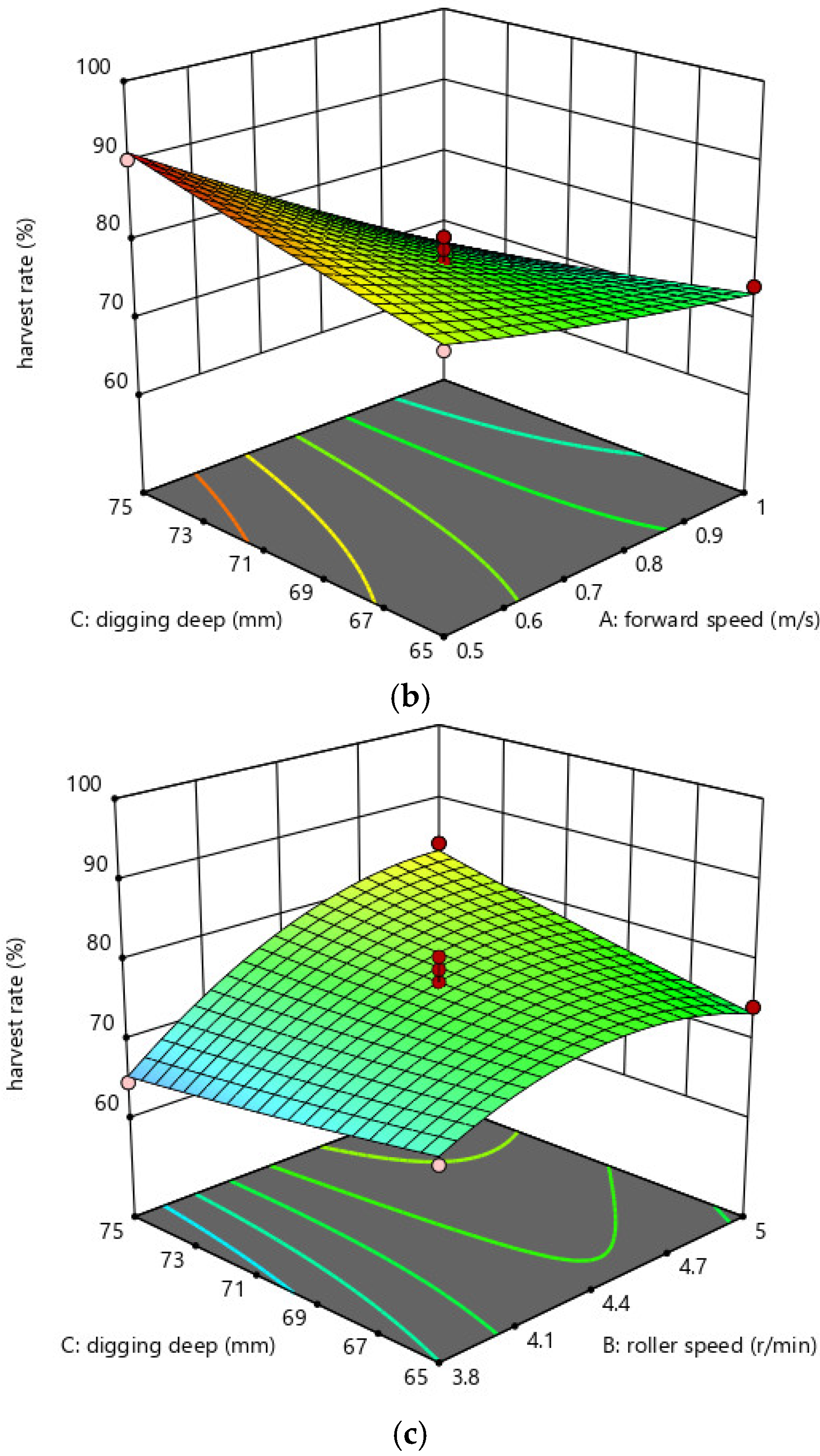
4.3.2. Effect of Interaction Among Parameters

In order to have a more intuitive analysis of the impact of the interaction among different factors on the hard-shell clam harvesting rate, the response surface analysis was carried out on the simulation experiment results. Through response surface analysis, the effect of each factor on the harvest rate can be seen more intuitively. Figure 13 illustrates the interaction plots for AB, AC, and BC, respectively.
Based on the response surface diagram of the interaction among different factors shown in Figure 13a indicates that as the forward speed increases and the revolving speed remains constant, the hard-shell clam harvesting rate gradually decreases. The harvesting rate is higher when the forward speed is constant and the revolving speed is at the middle value. From Figure 13b, it can be seen that the harvesting rate is affected by the interaction between the forward speed and the digging depth. When the digging depth is constant, the harvesting rate gradually decreases as the forward speed increases. When the forward speed is constant, the harvesting rate decreases with increasing digging depth. Based on the response surface diagram of the BC interaction on the harvest rate, as shown in Figure 13c, it can be seen that when the revolving speed is constant, the harvesting rate does not change significantly with increases in the digging depth. When the digging depth is fixed, the harvesting rate initially increases and then decreases with increasing revolving speed.

4.3.3. Parameters Optimization

Because different factors have different impacts on the harvesting rate, several variables need to be optimized in order to improve the performance of the hard-shell clam harvesting mechanism, and therefore, to increase the harvest rate by using the method of finding the optimal working parameter combination. In order to obtain the optimal working parameters for each factor, the Optimization function of Design-Expert software was used for analysis and solution. According to the simulation results, the forward speed, digging depth, and roller speed jointly affected the harvesting rate. Through analysis, it was found that the optimal ideal parameters are a forward speed of 0.526 m/s, a roller speed of 4.772 r/min, and a digging depth of 73.067 mm. Based on the optimization results, the harvesting rate of the hard-shell clam harvesting mechanism was 91.173%, which was verified through subsequent simulation experiments.

5. Prototype Design and Field Testing

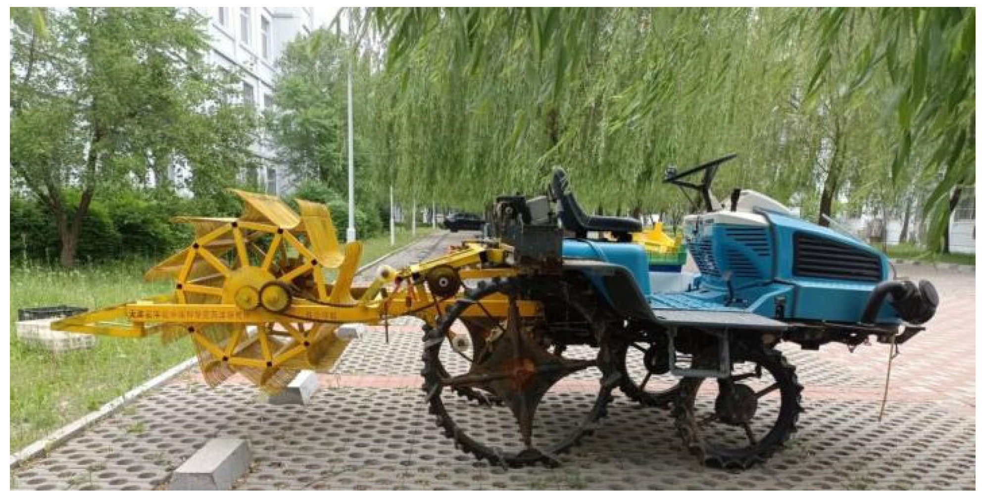
5.1. Prototype Production

In order to verify the feasibility of the optimal parameters obtained through the simulation experiment of the harvesting equipment, a prototype of the hard-shell clam harvesting mechanism was produced based on the simulation experiment. The parts and assembly drawings were completed with SolidWorks, and standard drawings of each part were produced for the later prototype production. The hard-shell clam harvesting mechanism was manufactured by Tianjin Xinsheng Mechanical Parts Manufacturing Co., Ltd., Tianjin, China, as shown in Figure 14.

5.2. Field Testing

5.2.1. Testing Purpose and Design

The main purpose of field testing was to ascertain the feasibility of the hard-shell clam harvesting device. The optimal values of the variable factors of the hard-shell clam harvesting mechanism were obtained through EDEM simulation analysis; therefore, these optimal parameters were used for the field test. The field test of the hard-shell clam harvesting mechanism was conducted in October 2023 at the hard-shell clam cultivation area of Haisheng Aquaculture Co., Ltd. in Tianjin, China, as shown in Figure 15a. The test site was divided into an adjustment area and a harvesting area. The adjustment area was 2000 mm in length where the harvesting mechanism was accelerated to the appropriate speed, so there were no hard-shell clams placed there. The harvesting area was 4000 mm in length and 980 mm in width, and 88 hard-shell clams were randomly placed on the surface, as shown in Figure 15b.

5.2.2. Test Results

Figure 16a shows the working diagram of the hard-shell clam harvesting mechanism. The field test was divided into three groups, and the number of harvested hard-shell clams was counted after each test, as shown in Figure 16b. The harvesting rate was recorded after each test. Through the field test, when the forward speed was 0.526 m/s, the roller speed was 4.772 r/min, and the digging depth was 73.067 mm, the harvesting rate of the hard-shell clam harvesting mechanism was listed in Table 8. As seen from the table, the harvesting rates were relatively stable across the tests. The field test results were relatively close to the EDEM simulation results, with a small amount of error, which can meet the expected requirements. The sources of error mainly came from the complex and varied conditions in the actual environmental setting [31].

6. Conclusions

(1)
Through the investigation of the condition of hard-shell clam cultivation and the physical parameters measurement results of hard-shell clams and soil, the key components of the hard-shell clam harvesting mechanism were designed, which can effectively harvest the mature clams and collect them into the collection box, solving the low efficiency problem in the manual harvesting process.
(2)
By establishing a discrete element model of hard-shell clams and cultivation sediment in EDEM software and importing the simplified model of the harvest machine into EDEM for simulation analysis, the soil disturbance and harvesting conditions during the operation of the machine were studied. Factors affecting the harvesting rate were found to be the forward speed, roller speed, and digging depth in decreasing order of influence by simulating harvesters operating at different forward speeds. The parameters were then optimized to achieve the optimal work parameters of forward speed of 0.526 m/s, roller speed of 4.772 r/min, and digging depth of 73.067 mm, which were validated by field testing, corroborating their feasibility level that was consistent with a comparative analysis of simulations and practical experiments.
(3)
This shellfish harvesting machine is designed for the problems of low efficiency and high cost of manual harvesting of shellfish in tidal flats. The harvesting machine has the advantages of improving efficiency and reducing labor intensity, which is of positive significance to the development of shellfish aquaculture industry in tidal flats, but there are also shortcomings that can be improved. For example, the crushing rate of clams has not been studied in depth, and the damage rate and the factors affecting the damage rate can be further studied to optimize the structure of the harvesting machine.

Author Contributions

Conceptualization, Y.J. and H.W.; methodology, B.H.; software, B.H. and X.W.; validation, S.L., L.Y., and S.F.; formal analysis, M.C. and Z.C.; investigation, Y.Z.; resources, J.H.; writing—original draft preparation, X.W. and H.W.; writing—review and editing, H.W.; funding acquisition, T.Z. All authors have read and agreed to the published version of the manuscript.

Funding

This research was funded by the Open Fund Project of Key Laboratory of Smart Breeding of the Ministry of Agriculture and Rural Affairs in 2024, grant number 2024-TJAULSBF-2506, the Key R&D Program of Shandong Province, grant number 2023CXGC010411, the Central Guidance for Local Scientific and Technological Development Fund (the Excellent Special Commissioner of Agricultural Science and Technology Project), grant number 24ZYCGSN00360, the National Key Research and Development Program “Marine Fisheries” Special Project, grant number 2023YFD2400800, the Open Fund Project of Key Laboratory of Smart Breeding of the Ministry of Agriculture and Rural Affairs in 2024, grant number 2024-TJAULSBF-2102, and 2024-TJAULSBF-2507, and the National Natural Science Foundation of China, grant number 62305246.

Institutional Review Board Statement

Not applicable.

Informed Consent Statement

Not applicable.

Data Availability Statement

The original contributions presented in this study are included in the article. Further inquiries can be directed to the corresponding author.

Acknowledgments

We would like to acknowledge Shangdong Dehemingxing Biotechnology Co., Ltd., Weifang, China and Key Laboratory of Smart Breeding (Co-construction by Ministry and Province), Ministry of Agriculture and Rural Affairs, Tianjin Agricultural University.

Conflicts of Interest

Author Jincheng Hu was employed by the company Tianjin Haisheng Aquaculture Co., Ltd. The remaining authors declare that the research was conducted in the absence of any commercial or financial relationships that could be construed as a potential conflict of interest.

References

  1. Mu, G.; Duan, F.; Yang, J. Research Progress on Benthic Bivalve Capture Machines. J. Dalian Ocean. Univ. 2020, 35, 19–30. [Google Scholar]
  2. Song, J.; Chang, Y. Introduction, Artificial Breeding and Developmental Technology of Hard-shell Clam in Northern China. China Fish. 2009, 9, 50–51. [Google Scholar]
  3. Zhang, H.; Li, P.; Zhang, H.; Huang, W.; Zhang, G.; Mu, G.; Li, X. Design and Experiment of Cone Disk Centrifugal Shellfish Seeding Device. Front. Mar. Sci. 2023, 10, 1136844. [Google Scholar] [CrossRef]
  4. Shentu, L.; Gong, Z.; Sun, X.; Zhao, Q.; Sun, C. Design of the Self-propelled Clam Harvester. J. Chin. Agric. Mech. 2015, 36, 192–195. [Google Scholar]
  5. Lepofsky, D.; Smith, N.F.; Cardinal, N.; Harper, J.; Morris, M.; Gitla, E.W.; Bouchard, R.; Kennedy, D.I.D.; Salomon, A.K.; Puckett, M. Ancient shellfish mariculture on the northwest coast of north America. Am. Antiq. 2015, 80, 236–259. [Google Scholar] [CrossRef]
  6. Dimitrijevi, M.; Zuber Bogdanovi, I.; Grkovi, N.; Aksentijevi, K.; Nikoli, M.; Pavievi, Z.; Lauevi, D. Sustainability of Shellfish Aquaculture in Montenegro-perspectives. Vet. Glas. 2022, 76, 125. [Google Scholar]
  7. Bargione, G.; Barone, G.; Virgili, M.; Lucchetti, A. Evaluation and quantification of shell damage and survival of the striped venus clam (Chamelea gallina) harvested by hydraulic dredges. Mar. Environ. Res. 2023, 187, 105954. [Google Scholar] [CrossRef]
  8. Stewart, N.L.; Brenda, K. Kelp Forests Versus Urchin Barrens: Alternate Stable States and Their Effect on Sea Otter Prey Quality in the Aleutian Islands. J. Mar. Biol. 2012, 2012, 1–12. [Google Scholar] [CrossRef]
  9. Stevick, B.C.; Carson, H.S.; Working, O. The Pace of Harvest and Recovery in Geoduck Clam Stocks Fifty Years into the Fishery. Fish. Res. 2021, 42, 106018. [Google Scholar] [CrossRef]
  10. Weng, Z.; He, H. YXF-4 Type Snail and Shellfish Suction Machine. Agric. Mach. 1982, 242, 27–28. [Google Scholar]
  11. Hauton, C.; Hall-Spencer, J.M.; Moore, P.G. An Experimental Study of the Ecological Impacts of Hydraulic Bivalve Dredging on Maerl. ICES J. Mar. Sci. 2003, 60, 381–392. [Google Scholar] [CrossRef]
  12. Gilkinson, K.D.; Fader, G.B.J.; Gordon, D.C., Jr.; Charron, R.; McKeown, D.; Roddick, D.; Kenchington, E.L.R.; MacIsaac, K.; Bourbonnais, C.; Vass, P. Immediate and Longer-term Impacts of Hydraulic Clam Dredging on an Offshore Sandy Seabed: Effects on Physical Habitat and Processes of Recovery. Cont. Shelf Res. 2003, 23, 1315–1336. [Google Scholar] [CrossRef]
  13. Goldberg, R.; Mercaldo-Allen, R.; Rose, J.M.; Clark, P.; Kuropat, C.; Meseck, S.; Pereira, J. Effects of Hydraulic Shellfish Dredging on the ecology of a Cultivated Clam Bed. Aquac. Environ. Interact. 2012, 3, 11–21. [Google Scholar] [CrossRef]
  14. Tuck, I.D.; Bailey, N.; Harding, M.; Sangster, G.; Breen, M. The Impact of Water Jet Dredging for Razor Clams, Ensis spp., in a Shallow Sandy Subtidal Environment. J. Sea Res. 2000, 43, 65–81. [Google Scholar] [CrossRef]
  15. Yamazaki, S.; Hiyonno, J.; Toshihiro, W. Damage to the Foot of Chosen Surf Clam by the Use of a Trap Net. Bull. Jpn. Soc. Sci. Fish. 2002, 68, 368–373. [Google Scholar]
  16. Zhang, W. The Design and Research of Sinonovacula Constricta Harvester. Master’s Thesis, Fujian Agriculture and Forestry University, Fuzhou, China, 2018. [Google Scholar]
  17. Lu, J.; Zhou, Y.; Shen, C.; Lu, S.; Tu, L.; Xue, A. Design and Experiment of Self-propelled Shellfish Harvester. Fish. Mod. 2021, 48, 85–90. [Google Scholar]
  18. Zhang, Y.; Xie, F.; Fu, Z.; Zheng, P.; Liu, D.; Wang, X. Research Status and Prospect of Intelligent Side-deep Fertilization Device for Synchronous Rice Planting by Machine. Agric. Equip. Veh. Eng. 2023, 61, 51–55. [Google Scholar]
  19. Ji, L.; Jiang, X.; Ma, Y.; Tong, J.; Hu, B. Bionic Design of a Potato Digging Shovel with Drag Reduction Based on the Discrete Element Method (DEM) in Clay Soil. Appl. Sci. 2020, 10, 7096. [Google Scholar] [CrossRef]
  20. Liu, S.; Weng, S.; Liao, Y.; Zhu, D. Structural Bionic Design for Digging Shovel of Cassava Harvester Considering Soil Mechanics. Appl. Bionics Biomech. 2014, 11, 1–11. [Google Scholar] [CrossRef]
  21. Fu, W.; Chen, H.; Kan, Z. Optimization of Parameters for Vibrating Soil-loosening Shovel of Carrot Harvester. Trans. Chin. Soc. Agric. Eng. 2011, 27, 46–50. [Google Scholar]
  22. Deng, W.; Wang, C.; Sun, H.; Hou, Z.; Wang, F. The Mechanical Model Building of the Potato Excavator Digger Shove. J. Agric. Mech. Res. 2014, 36, 84–86. [Google Scholar]
  23. Fakayode, A.O. Size-based Physical Properties of Hard-shell Clam (Mercenaria mercenaria) Shell Relevant to the Design of Mechanical Processing Equipment. Aquac. Eng. 2020, 89, 102056. [Google Scholar] [CrossRef]
  24. Boikov, A.V.; Savelev, R.V.; Payor, V.A. DEM Calibration Approach: Orthogonal Experiment. J. Phys. Conf. Ser. 2019, 1210, 012025. [Google Scholar] [CrossRef]
  25. Wang, C.; Ding, L.; Dou, F.; Kang, Z.; Li, F.; Li, J. Design and Experiment of Comb Type Picking Device of Ground Jujube. J. Shihezi Univ. (Nat. Sci.) 2021, 39, 409–414. [Google Scholar]
  26. Huang, B.; Pan, H.; Wang, X.; Li, Y.; Zhang, T.; Li, S.; Jiang, Y.; Wang, F. Parameter Calibration of Discrete Element Simulation for the Interaction Between Heavy Soil and Soil-engaging Components in Shellfish Culture. Can. J. Soil Sci. 2023, 104, 38–53. [Google Scholar] [CrossRef]
  27. Li, Y.; Li, F.; Xu, X.; Shen, C.; Meng, K.; Chen, J.; Chang, D. Parameter Calibration of Wheat Flour in Discrete Elements Based on Particle Scaling. Trans. Chin. Soc. Agric. Eng. 2019, 35, 320–327. [Google Scholar]
  28. Acquah, K.; Chen, Y. Discrete Element Modelling of Soil Compaction of a Press-wheel. AgriEngineering 2021, 3, 278–293. [Google Scholar] [CrossRef]
  29. Zhao, H.; Zhang, D.; Yang, L.; Cui, T.; Song, W.; He, X.; Wu, H.; Dong, J. Optimal Design and Experiment of Critical Components of Hand-pushing Corn Plot Precision Planter. Agriculture 2013, 12, 2103. [Google Scholar] [CrossRef]
  30. Zhao, H.; Deng, W.; Xie, S.; Zhao, Z. Performance Optimization and Experimental Study of Small-scale Potato-grading Device. Agriculture 2024, 14, 822. [Google Scholar] [CrossRef]
  31. Xu, X.; Chen, S.; Hu, L. Design and Analysis of Excavation Mechanism for Pseudo-ginseng Harvester. J. Chin. Agric. Mech. 2022, 43, 32–39. [Google Scholar]
Figure 1. Model of the whole clam harvester.
Fishes 10 00217 g001
Figure 2. Overall structure of digging system: 1—Frame, 2—Tines, 3—Fixing rack, 4—First chain wheel drive, 5—Second chain wheel drive, 6—Transmission shaft, 7—Roller support, 8—Collection box fixing rack, 9—Collection box.
Fishes 10 00217 g002
Figure 3. Structure and composition of the tines’ assembly: 1—Tines, 2—Fixed shaft, 3—Crossbar, 4—Surrounding bars.
Fishes 10 00217 g003
Figure 4. Stress analysis diagram of the tines.
Fishes 10 00217 g004
Figure 5. Left view of the hooked rotor: 1—Tines, 2—Surrounding bars, 3—Fixed shaft.
Fishes 10 00217 g005
Figure 6. Geometric dimensions of the hard-shell clams.
Fishes 10 00217 g006
Figure 7. The measurement of the trilateral dimensions of the hard-shell clams.
Fishes 10 00217 g007
Figure 8. The top view of the hooked rotor.
Fishes 10 00217 g008
Figure 9. Hard-shell clam discrete element model.
Fishes 10 00217 g009
Figure 10. Soil–hard-shell clam discrete element model. (a) Soil particle factory; (b) Bottom soil model generation; (c) Hard-shell clam model generation; (d) Soil-clams discrete element model generation.
Fishes 10 00217 g010
Figure 11. Before and after simulation process of hard-shell clam harvesting by the machine. (a) Before harvesting; (b) After harvesting.
Fishes 10 00217 g011
Figure 12. The operation process of the clam harvester. (a) Tines enter soil for 0.01 s; (b) Tines enter soil for 0.02 s; (c) The tines are raised for 0.49 s; (d) The tines are raised for 1.35 s.
Fishes 10 00217 g012
Figure 13. The response surface plots of the interaction among different factors. (a) Response surface plot of the effect of AB interaction on the harvesting rate; (b) Response surface plot of the effect of AC interaction on the harvesting rate; (c) Response surface plot of the effect of BC interaction on the harvesting rate.
Fishes 10 00217 g013aFishes 10 00217 g013b
Figure 14. Whole machine of hard-shell clam harvesting mechanism.
Fishes 10 00217 g014
Figure 15. Test site and pre-processing. (a) Testing site; (b) Clam laying.
Fishes 10 00217 g015
Figure 16. Hard-shell clam harvesting mechanism field test. (a) Working diagram of the harvesting mechanism; (b) Harvested hard-shell clams.
Fishes 10 00217 g016
Table 1. Whole machine parameters.
ParametersValues
Dimensions/mm2480 × 1130 × 950
Operating width/mm980
Digging depth/mm0~130
Engine power/kw18.5
Traveling speed/km/h0~5
Table 2. Triaxial dimensions of hard-shell clams.
Mature ShellJuvenile Shell
Lenth/cm4~61~3
Width/cm3~50.8~2
Thickness/cm2~40.2~1
Table 3. Basic parameters of the clam discrete element model.
ParametersValues
Mature clams trilateral dimensions (length × width × height)/(mm)44 × 34 × 24
Juvenile clams trilateral dimensions (length × width × height)/(mm)18 × 12 × 6
Poisson’s ratio 0.25
Density/(g/cm3)1.745
Shear Modulus (MPa)11
Table 4. Discrete element model simulation parameters.
ParametersValues
Soil Density/(g/cm3)1.04
Soil Poisson’s Ratio0.45
Soil Shear Modulus/(MPa)1
Soil-Soil Recovery Coefficient0.3
Soil-Soil Static Friction Coefficient0.3
Soil-Soil Rolling Friction Coefficient0.5
Poisson’s Ratio of Digging Instrument’s Material0.29
Density of Excavation Instrument’s Material/(g/cm3)7.86
Shear Modulus of Excavation Instrument’s Material/(MPa)7.9 × 104
Soil–Surface energy between Soil/(J/m2)8.05
Table 5. Factor level table.
LevelForward Velocity (m/s)Digging Depth (mm)Revolving Speed (r/min)
10.5653.8
20.75704.4
31755.0
Table 6. Experiment plan and results.
Experiment PlanForward Velocity (m/s)Digging Depth (mm)Revolving Speed (r/min)Harvesting Rate R (%)
11654.474.2
20.75653.870.1
30.5654.480.6
40.75655.074.2
50.5705.087.1
60.75704.474.2
71703.861.3
81705.067.8
90.75704.475.8
100.75704.477.4
110.75704.479
120.5703.877.4
130.75704.480.6
140.5754.490.3
150.75753.864.5
160.75755.083.9
171754.467.8
Table 7. Variance analysis of the hard-shell clam harvesting rate.
Simulation ItemSum of SquaresDegrees of FreedomMean SquareFpSignificance
Model933.149103.6819.290.0004**
A516.811516.8196.16<0.0001**
B197.011197.0136.660.0005**
C6.8516.851.270.2963×
AB2.5612.560.47630.5123×
AC64.80164.8012.060.0104*
BC58.52158.5210.890.0131*
A21.1611.160.21590.6563×
B286.21186.2116.040.0052**
C20.378910.37890.07050.7983×
Residual37.6275.37
Lack of Fit12.0234.010.62620.6350×
Error25.6046.40
Total970.7616
Note: When p ≤ 0.01, it is extremely significant, indicated by “**”; when 0.01 < p ≤ 0.05, it is significant, indicated by “*”; when p > 0.05, it is not significant, indicated by “×”.
Table 8. Field test harvesting rate under different optimal parameters.
Test GroupNumbers of Layout (Pieces)Harvested Hard-Shell Clams (Pieces)Field Harvesting Rate (%)Simulation Harvest Rate (%)
188809191.173
2888192
3888091
Disclaimer/Publisher’s Note: The statements, opinions and data contained in all publications are solely those of the individual author(s) and contributor(s) and not of MDPI and/or the editor(s). MDPI and/or the editor(s) disclaim responsibility for any injury to people or property resulting from any ideas, methods, instructions or products referred to in the content.

