Article

Multi-Wavelength Quantum Key Distribution Emulation with Physical Unclonable Function

Cybersecurity Research Lab, Northern Arizona University, Flagstaff, AZ 86011, USA
*
Authors to whom correspondence should be addressed.
These authors contributed equally to this work.
Cryptography 2022, 6(3), 36; https://doi.org/10.3390/cryptography6030036
Submission received: 7 June 2022 / Revised: 29 June 2022 / Accepted: 4 July 2022 / Published: 6 July 2022

Abstract

:
This work details the theory and implementation of a multi-wavelength quantum key distribution (QKD) emulation system with a physical unclonable function (PUF). Multi-wavelength QKD can eliminate the need to share a subsection of the final key for eavesdropper detection and allow for ternary and quaternary data transmission. The inclusion of the PUF adds an additional layer of security. We provide preliminary error analysis of our emulation system. To support this work, we introduce a bitwise transform operator that enables binary output of the PUF to satisfy the ternary and quaternary input requirements of the QKD system.

1. Background Information

1.1. Motivation

Quantum computers threaten modern security standards, and new quantum computer-resistant protocols are needed. The two main areas of cryptography include symmetric and asymmetric cryptography. In symmetric cryptography, two parties use the same secret key for encryption and decryption, and both parties must establish the secret key ahead of time. In asymmetric cryptography, participants use mathematically related public–private key pairs to encrypt and decrypt. The sender encrypts the message with the receiver’s public key, and the receiver decrypts with their own private key. Examples of asymmetric encryption methods include Rivest–Shamir–Adleman (RSA) and Elliptic Curve Cryptography (ECC). The security of RSA and ECC rely on the difficulty of prime factorization for large numbers and solving the elliptic curve discrete logarithm problem, respectively. With current computing power, both these problems take many years to brute force, so they remain secure; however, quantum computers promise to factor large integers and solve discrete logarithms quickly, rendering RSA and ECC insecure in key exchange protocols [1,2]. Because quantum computers threaten modern security, there is an urgent need for post-quantum key exchange protocols.
One such key exchange method includes Quantum Key Distribution (QKD), a key distribution method that relies on quantum mechanical properties as opposed to computational assumptions [3]. While offering unconditional security in theory, practical implementation is difficult, leading to issues that hackers can exploit. Additionally, hardware limitations reduce throughput. Furthermore, many QKD protocols require a subsection of the final cryptographic key to be sacrificed to test for eavesdroppers, thus reducing the final key length. To address practical issues and improve efficiency, traditional QKD protocols have been modified in a variety of ways. In this paper, we present and implement multi-wavelength QKD protocols with a physical unclonable function (PUF) to increase security and improve data throughput.

1.2. QKD Overview

A field of cryptography called QKD is thought to be unconditionally secure, even with the commercialization of quantum computers [2,4]. QKD describes a family of secure communication protocols that use quantum states to generate a cryptographic key between two parties, Alice and Bob, which can then be used for encryption [5]. While traditional secure communication protocols may be subject to eavesdroppers, QKD ensures eavesdropper detection, making it more secure than other methods [5,6].

Security Based on Quantum Mechanics

QKD relies on quantum mechanical properties to ensure security; for instance, quantum state collapse during measurement, irreversibility of measurement, the Heisenberg uncertainty principle, the no cloning theorem, and entanglement [5,7]. When a quantum state is measured, the state collapses into one of the possible states and cannot be reversed. For security purposes, this can mean that the act of measuring results in permanent changes that can be used to detect changes that an eavesdropper may make on the QKD system. Additionally, when two properties are related by the Heisenberg uncertainty principle, certainty in one of the properties results in uncertainty in the other, and vice versa. For example, knowing a photon’s polarization in the rectilinear basis results in uncertainty of the photon’s diagonal polarization state [8,9,10]. For security, this can mean that random, uncontrollable changes may be introduced into the QKD system by eavesdropper presence. For quantum entanglement, when two particles are entangled, they are linked in such a way that measuring one particle will instantaneously affect the state of the other particle, regardless of distance. Furthermore, the state of either particle cannot be predicted prior to measurement [7]. Entangled particles follow the property that if the measurement of each particle is performed in the same basis, then their results will be anti-correlated. For different bases, there is no correlation between the result. Eavesdropper detection can be performed using the Bell Inequality [11]. Such properties are the foundations of QKD security.

1.3. QKD Protocols

A number of QKD protocols exist, each with their own strengths and weaknesses. BB84 is a notable protocol with many other variations similar to it, including B92, SARG04, SSP99, and some error correction and throughput increasing modifications. E91 is another notable QKD protocol based on quantum entanglement. In this section, we provide a review of the protocols.

1.3.1. BB84

Named after creators, Charles Bennett and Gilles Brassard in 1984, BB84 encodes data in single-photon polarization states, such that Alice and Bob can communicate limited information and generate identical, secret cryptographic keys [9,12].
A linearly polarized photon at angle θ in the x–y plane is represented by | θ = c o s ( θ ) | 0 + s i n ( θ ) | 1 , where the | 1 and | 0 represent the vertical and horizontal polarization states, respectively [13]. A single photon polarization is measured with respect to a certain direction. BB84 uses two bases: rectilinear and diagonal. The rectilinear basis can be thought of as 0 (horizontal) and 90 (vertical); the states can be written as | 0 + , | 1 + . The diagonal basis can be thought of as a superposition of the horizontal and vertical states, or more simply, 45 and 135 . These states can be written as | 0 × , | 1 × . Using these four states, Alice and Bob can communicate by encoding data in photon polarization.
The BB84 protocol works as follows: first, Alice randomly generates a stream of bits and a random sequence of polarization bases, either rectilinear or diagonal. Next, Alice encodes her random bits in photon polarization states by polarizing the photons according to a pre-specified encoding scheme. For example, in traditional BB84, she will send a binary 0 with a 0 (rectilinear) or 45 (diagonal) polarized photon; and she will send a binary 1 with a 90 (rectilinear) or 135 (diagonal) polarized photon. She sends the polarized photons to Bob via the quantum channel (e.g., fiber optic or free space). For each photon he receives, Bob randomly chooses one of the bases to measure the photon and interprets the resulting bit based on the same encoding chart Alice used. Next, Alice and Bob communicate their bases choices via the classical channel (e.g., internet), and they discard all bits in positions where mismatching bases were used. If Eve did not interfere, their keys should contain low error and in theory, should be identical. To confirm, Alice and Bob share a subsection of their keys and compare to check for low error. If the error is low, the remaining bits are used as the final cryptographic key; otherwise, they conclude that Eve interfered, discard their keys, and try again. Note, in BB84, a portion of the key must be sacrificed and exposed in order to estimate the presence of interference.

Eavesdropper Detection

For an eavesdropper, Eve, to intercept Alice and Bob’s communication, Eve must measure the photon, thus collapsing the photon polarization state in an irreversible, uncontrollable way that Alice and Bob can detect. Eve will randomly choose a basis, interpret the bit, and send a new photon in the same measured polarization state to Bob. She has a 50/50 chance of guessing the same basis as Alice. If she guesses correctly, then she should not produce detectable errors 50% of the time; however, if she guesses incorrectly, she introduces errors 50% of the time, reducing Bob’s percentage of correct bits to 25%. If enough bits are sent, Alice and Bob can detect this error when they compare a subsection of their key. Eve may also try cloning the photon and, instead, measuring the cloned photon state; however, Eve is unable to create a copy due to the no cloning theorem [14].

Practical Implementation, Attacks, and Decoy States

In theory, BB84 seemingly offers unconditional security, but in practice, weaknesses exist due to hardware limitations. Components such as the single photon detectors introduce problems, and attempts to solve these problems exist ([15]), but the most notable limitations stem from imperfect single photon sources. In order for the protocol to work, Alice must have a perfect single photon source that emits one photon per pulse. However, in practice, single photon sources are imperfect and may emit more than one photon per pulse and sometimes zero photons per pulse. An eavesdropper, Eve, can exploit this issue through a photon number splitting (PNS) attack where she “splits” the extra photons on multi-photon pulses, and allows the remaining photons to continue transmission to Bob. This way, Eve can measure the extra photons without alerting Alice and Bob. Eve may also block all single photons from reaching Bob to ensure only the multi-photon pulses are used [7]. One method of combatting this attack includes using decoy states that Eve cannot easily distinguish from the real states, so she will make detectable changes to the decoy state yield [16,17,18]. While this method and other modifications to decoy state protocols help mitigate information obtained by Eve, the imperfections of the practical BB84 system remains a major weakness.

1.3.2. B92, SARG04, SSP99, and QKD Protocols after BB84

Many QKD protocols exist, including B92, SARG04, SSP99, and others that slightly modify existing protocols. The B92 protocol, developed by Charles Bennett in 1992, uses two non-orthogonal states as opposed to the four polarization states from two orthogonal bases in BB84 [19,20]. Bob is able to deterministically obtain information on certain bits, allowing Alice and Bob to calculate matching cryptographic keys [21]. While simpler, the throughput in B92 is halved and is not as efficient as BB84. Another protocol similar to BB84 is SARG04 [21,22,23]. Described by Scarani, Acin, Ribordy, and Gisin in 2004, SARG04 is essentially the same as BB84, except the classical communication phase differs significantly. Instead of communicating basis choices, Alice announces one of her pairs of non-orthogonal states, allowing Alice and Bob to determine specific bits with certainty. While less efficient than BB84, SARG04 has the advantage of countering PNS attacks. Another protocol created by Pasquinucci and Gisin in 1999 is called the Six-State Protocol (SSP99) and uses six polarization states on three orthogonal bases [20,24]. With three bases to choose from, Eve has a less likely chance of choosing correctly; thus, she is more likely to introduce detectable error. In another modification, Lo et al. assign probabilities for basis selection, thus reducing the number of discarded bits [25,26]. Other protocols aim to correct errors in the final key; in 2003, Buttler et al. developed Winnow, which uses Hamming code to correct errors in the key reconciliation phase, but shares more information on the public channel [27,28]. Reconciliation algorithms have been applied to QKD protocols to increase efficiency during the reconciliation phase [29]. Another protocol that uses the advantage distillation technology in combination with decoy states has been shown to improve transmission distance and maximal error rate tolerance [30]. Finally, some methods of combining QKD with post-quantum cryptography have also been discussed [3]. These QKD protocols and modifications attempt to reduce errors and increase throughput, without sacrificing security.

1.3.3. E91

E91 is an entanglement-based QKD protocol introduced by Artur Ekert in 1991. The protocol is similar to BB84, except E91 utilizes a source that emits pairs of spin- 1 2 particles in a singlet state in order to generate a secret cryptographic key [31]. Because the particle pairs are entangled with one another, measuring one of the particles will instantaneously affect the other particle regardless of distance. Before measurement, the particles will be in a superposition of spin up and spin down states. If Alice and Bob measure in the same basis, then their results will be anti-correlated (e.g., if Alice measures spin up, then Bob’s particle must be spin down, and vice versa) [31]. They can use similar steps in the BB84 protocol to generate matching cryptographic keys by randomly selecting bases, communicating bases, and so on, as described in BB84. However, the main difference in E91 is that entangled particles are used. To check for eavesdroppers, Alice and Bob use the Bell Inequality, which can be used to indicate whether the source or transmission has been intercepted or compromised [11,31]. A major advantage of E91 is not being limited to physical distance, as in BB84, making E91 more ideal in applications such as satellite communications. A number of entanglement-based QKD protocols exist and offer an alternative to the previously mentioned QKD methods.

2. Multi-Wavelength QKD with a PUF

Like the protocols mentioned previously in Section 1.3.2, we propose a unique QKD setup that could be applied to different QKD protocols. Our work includes adding more than one wavelength and including a physical unclonable function (PUF). Multi-wavelength QKD has not been used with a PUF to create the encoding schemes in our work, to our knowledge. The additional wavelength enables different protocols using ternary and quaternary data. In a ternary protocol, Alice and Bob no longer need to use a subsection of their key to detect eavesdroppers, enabling longer key lengths. Similar to previous work, we also address the security issues introduced by practical limitations. Our method includes adding a PUF as an additional layer of security, since adversaries must have access to the PUF to intercept the data transmission. This is useful against QKD attacks since an eavesdropper cannot obtain the final key without access to the PUF or PUF data.
In Section 2.1, we describe the encoding schemes allowed by multi-wavelength QKD. In Section 2.2, we discuss the entire multi-wavelength protocol with a PUF included.

2.1. Multi-Wavelength QKD

Multi-wavelength QKD involves adding multiple wavelengths, allowing for different protocols and data to be sent. With the traditional single wavelength, Alice only has four polarization states to encode bits with (two per basis). Adding a second wavelength doubles the amount of polarization options that Alice can encode data with, since Alice can choose from four states per wavelength for a total of eight possible states. These additional states allow for different encoding schemes based on ternary or quaternary state input stream values (as opposed to binary for bits). Just as binary means we have two states to send data with, using ternary or quaternary data means that we have three or four states to send data with. Figure 1a,b show two potential encoding schemes for a ternary or quaternary protocol, respectively [6].

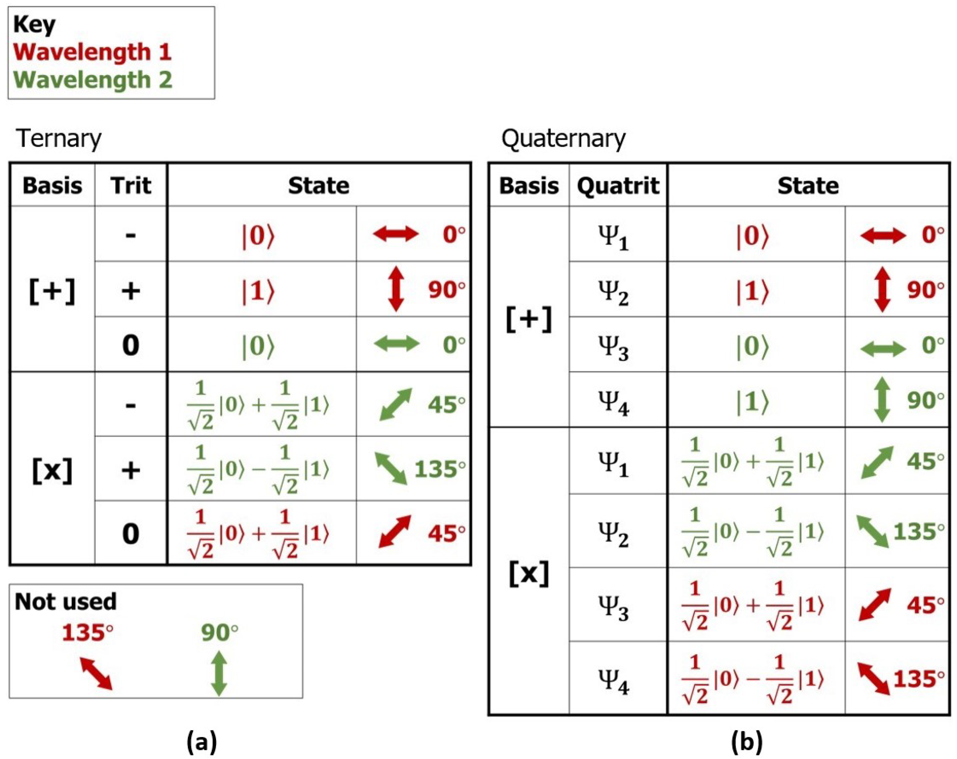
2.1.1. Ternary Protocol

The ternary scheme introduces unused states and can be applied to traditional QKD protocols; one advantage of unused states is that their presence can indicate eavesdropper interference without Alice and Bob sacrificing a portion of the key, as is necessary in some QKD protocols such as BB84. Our modified ternary protocol chart (Figure 1a) has three data states: −, +, and zero. Notice that two states—135 for wavelength 1 and 90 for wavelength 2—were not used. These unused states will not be sent intentionally and act as “unused states”; in theory, they should not show up unless an eavesdropper is present. However, in practice, the unused states may show up due to various error sources. If the number of unused state cases is significantly large, then we conclude that an eavesdropper is present.

Problems and Improvements to the Ternary Protocol

One weakness of the ternary encoding scheme is that if the eavesdropper measures the wavelength, then she can obtain information about the key, thus reducing security. However, we can solve this by changing the unused states to reduce the amount of information an eavesdropper can obtain. The main issue with the ternary protocol as described above is that in the + basis, the green wavelength is only used when sending a zero state. Similarly, in the × basis, the red wavelength is only used when sending a zero state. This means that by knowing the bases choices (which becomes public information) and the wavelength of each photon, Eve can deduce the zero trits in the final key. To help reduce this security issue, the unused states can be used 50% of the time [6]. For example, we can use the red wavelength 90 to send a + trit in the + basis 50% of the time, and we can use the green wavelength 90 to send a + trit in the + basis the other 50% of the time. This means that an eavesdropper cannot assume that the green wavelength in the + basis signifies a 0 trit because sometimes the green wavelength can indicate a + trit. Similarly, we can do the same for the × basis + trit using the red and green wavelength 135 50% of the time. By changing the unused states, we can reduce the amount of information an eavesdropper can obtain and thus strengthen the protocol.

2.1.2. Quaternary Protocol

Unlike the ternary scheme, the quaternary scheme (Figure 1b) uses all eight states and sends quatrits instead of trits. One strength of the quaternary protocol is that because all states are used, an eavesdropper cannot infer information about the key, as mentioned in the previous section for the ternary protocol. The quaternary protocol is similar to the ternary protocol, but now Alice and Bob will send quatrits (e.g., Ψ 1 , Ψ 2 , Ψ 3 , or Ψ 4 ) as opposed to trits. Because of the additional states, throughput is also increased, and the quaternary protocol is a promising multi-wavelength protocol applicable to other traditional QKD protocols.

2.2. QKD with PUF

2.2.1. PUF Background

Another modification to traditional QKD is the inclusion of a physical unclonable function (PUF). A PUF is a hardware device that generates a random output value (called the response) based on an input (called the challenge) [32,33,34]. Together, the input and output are called a “challenge-response pair”. PUFs utilize random manufacturing defects, such as variations in length and doping concentration, gate oxide in integrated circuit chips. As a result of these random variations, the PUF response to a given challenge will be random, unique to the device, and consistent [33]. The PUF’s unique response is analogous to a “fingerprint” that can identify the device [35]. The “fingerprint” can be used to authenticate devices and generate cryptographic keys. Since the randomness is a product of manufacturing defects, manufacturers cannot produce a clone device, because, by definition, those defects are outside of their control. Furthermore, hackers require physical access to the device in order to complete the protocol, adding a layer of security to the system. This is advantageous in QKD protocols, since an eavesdropper cannot obtain the final cryptographic key without access to the PUF.

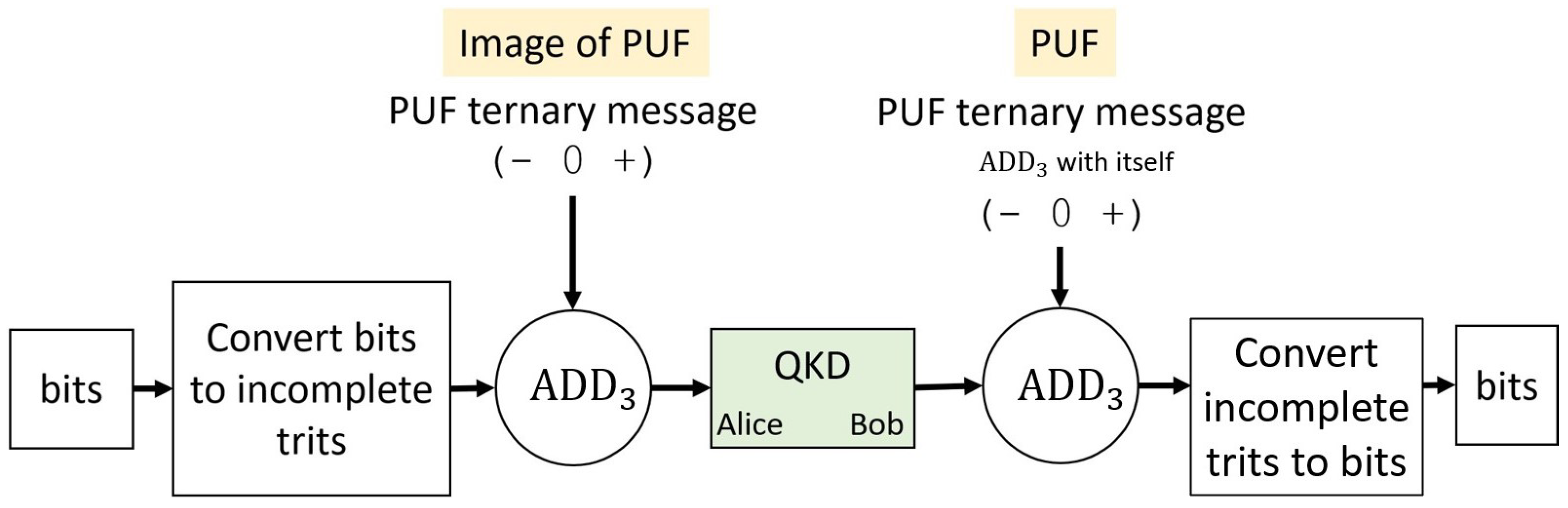
2.2.2. Ternary Protocol with a PUF

We use a resistive random-access memory (ReRAM) PUF, in combination with random bits, to generate the input stream of incomplete trits for the QKD system, which Alice encodes with polarized photons [34]. Figure 2 shows a protocol diagram for ternary input and output streams using a ReRAM PUF. First, Alice (server) will generate a random stream of bits and convert this stream to incomplete trits (e.g., zero becomes − and one becomes +, and no zero trits are present, hence the name “incomplete trits”). Next, she obtains a ternary message from the image of the PUF. The image of the PUF is the stored PUF responses on the server, while the PUF is the client’s real-time response readings. Ideally, these two response values should be identical, but in practice, differences in the server and client PUF responses may occur and are considered to be “errors”. Next, Alice will use addition modulo 3 (ADD 3 ) to combine the incomplete trits with the PUF ternary message. The function of this step is to obscure the incomplete trit input. Alice will use the result of the ADD 3 as the input for the QKD system, where it will then be encoded in the photons. She will use the chart in Figure 1a to encode her input in photon polarization states, then Bob (client) will choose a random basis for each photon and use the same chart to decode the ternary information. The second half of the diagram, after the QKD output, essentially undoes the first half, and should result in the same input bits. Because we start with incomplete trits, we expect, theoretically, only two of the three states to be present after unobscuring the QKD output. The unobscured QKD output is represented by the arrow directly after the right most ADD 3 in Figure 2. This unobscuring process is described in Section 2.2.3. If we observe three of the three states are present, we can determine eavesdropper presence (ignoring typical error sources such as noise, and assuming no error from the PUF). See Table 1 for a summary of what was described in this section.

2.2.3. Obscuring and Unobscuring Bitstreams with Addition

This section provides clarification of the use of addition for obscurement and later retrieval of the original input, as described in Section 2.2.2, and gives working examples thereof.
To obscure the input bitstream ( B 1 ), simply add another random bitstream to it, then modulo the output by the base of those streams. To then retrieve that input bitstream, perform addition modulo base with the second bitstream ( B 2 ) a total of base times: in base 2, we add modulo 2 (ADD 2 , + 2 ) with the second bitstream two times to get back to the original bitstream, and in base 3, we add modulo 3 (ADD 3 , + 3 ) with the second bitstream three times to get back to the original bitstream. This concept is illustrated below in base 2 on the left, and base 3 on the right, and accompanied by a respective truth table:
B 1 : 01010101 + 2 B 2 : 00100100 O : 01110001 + 2 B 2 : 00100100 B 1 : 01010101 B 1 : 01201201 + 3 B 2 : 21011012 O 1 : 22212210 + 3 B 2 : 21011012 O 2 : 10220222 + 3 B 2 : 21011012 B 1 : 01201201
B 1 B 2 B 1 + 2 B 2 0 0 0 0 1 1 1 0 1 1 1 0 B 1 B 2 B 1 + 3 B 2 0 0 0 0 1 1 0 2 2 1 0 1 1 1 2 1 2 0 2 0 2 2 1 0 2 2 1
Returning to the original bitstream can also be achieved by ADD 3 ing the second bitstream with itself after obscurement, and using the output thereof in the final, retrieving ADD 3 (this is the method used in Figure 2):
B 1 : 01201201 + 3 B 2 : 21011012 O : 22212210 B 2 : 21011012 + 3 B 2 : 21011012 B 2 : 12022021 O : 22212210 + 3 B 2 : 12022021 B 1 : 01201201

2.2.4. Quaternary Protocol with a PUF

The quaternary protocol is similar to that shown in the ternary diagram, except everything is one base higher (i.e., bits become trits and trits become quatrits). Figure 3 shows the quaternary protocol diagram. Now, Alice will start with a random stream of trits (instead of bits), convert them into incomplete quatrits, ADD 4 with a quaternary PUF message, and send quatrits into the QKD system. Alice and Bob will use the chart in Figure 1b to send the quatrits. Bob will take his received output and ADD 4 with the quaternary PUF message to unobscure, eliminate mismatching bases positions, convert back to trits, and obtain the final message. Like the ternary protocol, the second half of the diagram in Figure 3, after the QKD output, essentially undoes the first half, and should also result in the same input trits. Because we start with incomplete quatrits, we expect only three of the four states to be present after unobscuring with ADD 4 . If we have four of four states, then we can detect eavesdropper presence (again ignoring typical error sources such as noise). Overall, adding a second wavelength and employing a ReRAM PUF are changes applicable to traditional QKD protocols.

3. Bitwise Transform

The QKD system requires higher base input streams, but our current PUF implementations output binary streams [34,36,37]. Bitwise transform presents a scalable, consistent means to increase state of otherwise binary data, and satisfy the requirements of the QKD system. This work introduces the bitwise transform operator ( ) for base 3 ( 3 ), base 4 ( 4 ), and base 8 ( 8 ), and details patterns for further expansion. This section walks the reader through the mechanisms of bitwise transform using working examples with deliberate inputs that aim to illustrate all the possible input combinations.

3.1. TAPKI System

In order to discuss bitwise transform, we first must discuss the TAPKI system. TAPKI (Ternary Addressable Public Key Infrastructure) is the system by which we leverage the inherent entropy of physical devices, PUFs, to generate cryptographic keys. In short, the TAPKI system provides a consistent, repeatable, and secure means of PUF key generation by identifying the inconsistencies of each device and using that knowledge to purify the final key.
To keep the focus within scope, and on QKD, we concern ourselves with only the relevant outputs of TAPKI. If a deeper understanding of the details and mechanics of the TAPKI system is desired, see [38,39,40,41].
The three TAPKI outputs to consider are the stream (S), mask (M), and consequent key (K). The stream is the raw bitstream extracted from the addressed cells of the PUF. The mask denotes the fuzzy bits of the stream (mnemonic: “mask marks”); “fuzzy” meaning the bit’s state fluctuates non-deterministically between 0 and 1. To get a key (K), you apply the mask to the stream using the mask operator ( ). The mask operator is reductive: S M = K such that K < S . Any fuzzy bit, marked with a 1 in the mask, is removed from the stream (“masked”), and we are left with a consequent key:
S : 01010101 M : 00100100 K : 01 10 01 S : 01010101 M : 00100100 K : 011001
Normally, the key is 256 bits long and is the result of applying a 512 bit mask to a 512 bit stream. All of these parameters can be adjusted, but the mask must be the same size as the stream. Note that the longer the stream is than the key, the more selective you can be, and the more stable the output key becomes. With a 256 bit key and a 256 bit stream, you have no buffer and must proceed with all selected 256 bits. With a 256 bit key and a 512 bit stream, you have a 256 bit buffer and can cherry pick the best 256 bits to make up your key.

3.2. Ternary Transform

To suit the input requirements of the QKD system, we allow the inherent fuzzy bits of the stream to introduce the ternary state. We visualize this state through “expanded key notation.” An expanded key ( K E ) “expands” to preserve the location of the masked bits, represented by an X:
S : 01010101 M : 00100100 K E : 01 X 10 X 01
S M S M 0 0 0 0 1 X 1 0 1 1 1 X
Although we are using unstable bits to define the third state, we consistently mark those bits as inconsistent, thereby making the output stable.
The states of the expanded key map to the final states of the ternary key ( K 3 ) by adopting the form of a balanced ternary system (-1, 0, +1) and forgoing the postfix 1s:
Expanded Key ( K E ) 0 X 1 Ternary Key ( K 3 ) 0 +
In practice, there is no intermediate expanded key. Instead, we go from stream to ternary key directly, by applying the mask with the ternary transform operator:
S : 01010101 3 M : 00100100 K 3 : + 0 + 0 +
S M S 3 M 0 0 0 1 0 1 0 + 1 1 0

3.3. Quaternary Transform

The quaternary protocol described in Section 2.2.4 requires quaternary input. Achieving the fourth state at this point is straightforward. The third state was simply a reduction of the fourth state. With this in mind, we dive into the mechanisms of quaternary transform.
To re-iterate: the reason the output of ternary transform is stable, despite the use of fuzzy bits, is that whether the fuzzy bit is a 0 or 1, we mark that position with X. This is where quaternary transform differs:
S M S 3 M 0 0 0 1 0 1 0 + 1 1 0 S M S 4 M 0 0 0 0 1 1 1 0 2 1 1 3
Note that the output is now dependent on whether the masked bit is a 0 or a 1. This means, as is, the ephemeral state of the fuzzy bit determines the output, effectively propagating its inconsistency to the output.
In some cases, namely true random number generation, we leverage this property [42,43,44]. Other cases, such as TAPKI, require stability.
When stability is the priority, we cannot let the inconsistencies contaminate the output; thus, we must first expel the inconsistencies before use. Instead of using the raw stream, we exercise the mask operator as a means of processing, and feed the resulting key into the subsequent quaternary transform operation. The following example works under the assumption that the mask is configured to remove 50% of the bits: S M = K such that | K | = | S | 2 , where | K | is the cardinality of K.
We begin by cleaning up the stream:
S : 01010101 01010101 M : 00110011 10011001 K : 01011010
In order to trim the mask for re-use with the key in the next and final stage, we can do just that, or add more entropy to the system by splitting and XORing the mask to make it the right size:
M : 00110011 10011001 M 1 : 00110011 M 2 : 10011001 M : 10101010
Using this new mask, we perform quaternary transform:
K : 01011010 4 M : 10101010 K 4 : 12123030
S M S 4 M 0 0 0 0 1 1 1 0 2 1 1 3
The output conveniently takes the form of the binary interpretation, where order of the inputs matter. This form lends itself nicely to programming.
Thus, you can see how we had a means to achieve the fourth state all along, but simply did not use it. Using this concept of reduction and expansion, we will explore the octal base and the lesser states we get for free in between.

3.4. Octal Transform

When expanding the QKD system by adding more wavelengths, higher input will be required. Understanding quaternary transform, and operating under the same assumption—that the mask is configured to remove 50% of the stream—you will find that octal transform takes a very similar form, with only a minor alteration in the process.
The octal transform sequence is as follows: mask the stream to remove the fuzzy bits:
S : 01010101 01010101 M : 00110011 10011001 K : 01011010
split the mask into two chunks:
M : 00110011 10011001 M 1 : 00110011 M 2 : 10011001
and apply those two chunks through the octal transform operator:
K : 01011010 M 1 : 00110011 8 M 2 : 10011001 K 8 : 14275063
S M 1 M 2 S 8 M 1 8 M 2 0 0 0 0 0 0 1 1 0 1 0 2 0 1 1 3 1 0 0 4 1 0 1 5 1 1 0 6 1 1 1 7
Instead of XORing the mask after splitting, as in quaternary transform, we use both halves of the mask to attain the three needed inputs of octal transform. Of course, this is not the only way; see Section 3.6 for more options.
Remaining consistent, the output takes the form of the binary interpretation, where order of the inputs matter.
The eight states can be mapped as desired, and per application. The next section will explore how to utilize the lesser states that come with the octal base.

3.5. Restricting States

Which states you use and which ones you do not use is an implementation-dependent design decision. In the following truth tables, we took the liberty of generalizing to bitstream inputs of index i ( I i ).
Restriction can be achieved through elimination of states, represented by X:
I 1 I 2 I 3 I 1 8 I 2 8 I 3 0 0 0 0 0 0 1 1 0 1 0 2 0 1 1 3 1 0 0 4 1 0 1 X 1 1 0 X 1 1 1 X Total states     5    I 1 I 2 I 3 I 1 8 I 2 8 I 3 0 0 0 0 0 0 1 1 0 1 0 X 0 1 1 3 1 0 0 X 1 0 1 5 1 1 0 X 1 1 1 7 Total states     5   
or through assigning the same value to different states:
I 1 I 2 I 3 I 1 8 I 2 8 I 3 0 0 0 0 0 0 1 1 0 1 0 2 0 1 1 3 1 0 0 4 1 0 1 4 1 1 0 4 1 1 1 4 Total states     5    I 1 I 2 I 3 I 1 8 I 2 8 I 3 0 0 0 0 0 0 1 1 0 1 0 1 0 1 1 3 1 0 0 3 1 0 1 5 1 1 0 5 1 1 1 7 Total states     5   
With this concept, an octal system can be deployed for a two-state system, ready to scale at a moment’s notice:
I 1 I 2 I 3 I 1 8 I 2 8 I 3 0 0 0 0 0 0 1 1 0 1 0 X 0 1 1 X 1 0 0 X 1 0 1 X 1 1 0 X 1 1 1 X Total states     2    I 1 I 2 I 3 I 1 8 I 2 8 I 3 0 0 0 0 0 0 1 0 0 1 0 0 0 1 1 0 1 0 0 1 1 0 1 1 1 1 0 1 1 1 1 1 Total states     2   
Restricting states can be leveraged in cryptographic systems to increase confusion and to cleverly detect tampering, among other things. Future work will aim to connect restricting states to QKD unused states.

3.6. Alternative Mask Options

In the examples thus far, when needed, we have simply split the mask to create multiple inputs of shorter length, and XORed the splits to achieve a single, new input of shorter length. This approach is well suited for prototyping, yet further customization could be achieved by manipulating this step. The protocol architect is not limited here; the possibilities are nearly endless. Some alternate options to include in future work are:
1.
Shift mask before re-use.
2.
Hash mask before re-use.
3.
Generate a new mask for random addresses.
4.
Generate a new mask using the same addresses, but different parameters (e.g., combinations of current and temperature for memristor PUFs).
5.
Generate key as demonstrated, then recursively “XOR-AND-Tumble” the key and mask, feeding the outputs back into the system and repeating a defined, or random, number of times. To illustrate this novel XOR-AND-Tumble sequence in a manner that is easy to follow, we have labeled the initial inputs I i , and the corresponding outputs O i , indexed in the order in which they first appear:
I 1 : 01010101 I 2 : 00110011 O 1 : 01100110 & I 1 : 01010101 O 2 : 01000100 I 2 : 00110011 O 3 : 01110111 & O 1 : 01100110 O 4 : 01100110 O 2 : 01000100 O 5 : 00100010

3.7. Relationships of Expansion

This section points out two mathematical relationships of the work presented.
The binary logarithm of the base gives the number of bitwise transform inputs required to achieve that base:
base 4 l o g 2 ( 2 2 ) = 2 inputs base 8 l o g 2 ( 2 3 ) = 3 inputs base 16 l o g 2 ( 2 4 ) = 4 inputs
In other terms, the base doubles with every added input:
I 1 4 I 2 I 1 8 I 2 8 I 3 I 1 16 I 2 16 I 3 16 I 4 I 1 2 N I N

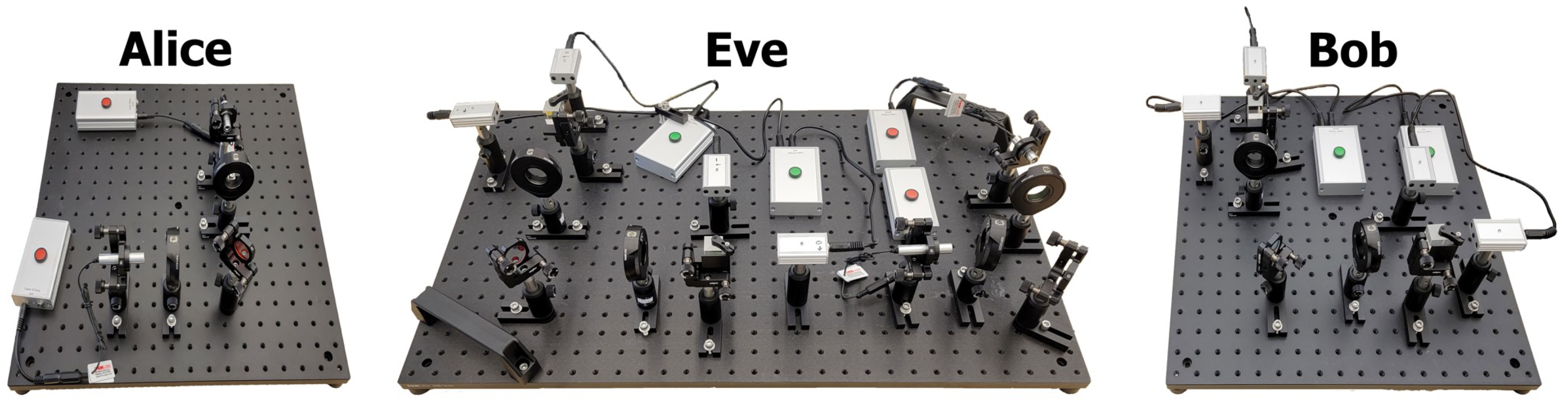
4. Building a QKD Emulation System to Test Protocols

In order to study the error rates of multi-wavelength protocols with a PUF, we customized and automated an educational QKD emulation kit from Thorlabs. The first section will discuss the operation and components of the original kit, and the second section will detail our modifications.

4.1. Original Thorlabs Emulation Kit

The original kit from Thorlabs is a free space emulation system with a single wavelength, designed for educational purposes, and thus does not use single photons. Alice is represented by a 635 nm laser and a half-wave plate. Bob is represented by a half-wave plate, a beamsplitter cube, and two photodetectors. Eve is represented by another polarizing beamsplitter cube, two more photodetectors, another 635 nm laser, and two half-wave plates.

4.1.1. Operation

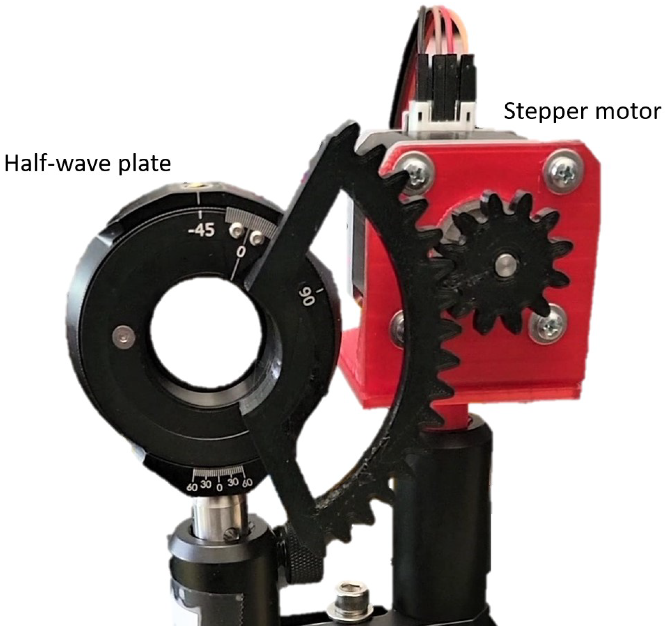
Setting up the Polarization Rotators

First, Alice generates a random stream of bits externally. Prior to sending the laser pulse, the half-wave plates must be rotated so that the laser can be polarized and measured accordingly. The user manually rotates Alice’s half-wave plate. A half-wave plate works by rotating the polarization of linearly polarized light so that the resulting polarization is two times the angle of the optical axis and incident polarized light. Therefore, to rotate the polarization in 45 degree increments, we must rotate the half-wave plate in one of four positions, where each position is half of 45 or 22.5 apart. Each position represents polarizing the photon at 0 , 90 , 45 , or 135 . The user also manually rotates Bob’s half-wave plate. Bob’s half-wave plate can be rotated in one of two positions—22.5 apart—corresponding to the rectilinear and diagonal bases.

Data Transmission

Next, the user can manually press a button to pulse the laser or hold the button down for a couple of seconds to generate a continuous beam. The laser beam is polarized through Alice’s half-wave plate, then travels to Bob’s half-wave plate. Bob’s half-wave plate represents “measurement” of the beam. At this stage, if Alice and Bob used “matching bases”, the laser beam should be either purely vertically or horizontally polarized. To illustrate this, the eight possible combinations for Alice and Bob’s basis choices are shown in Figure 4. Scenarios 1 through 4 represent Bob measuring in the rectilinear bases, and scenarios 5 through 8 represent Bob measuring in the diagonal basis. Notice that when they use mismatching bases (scenarios 3, 4, 5, 6), the resulting polarization is diagonal, and contains both horizontal and vertical components. This is important because at the polarizing beamsplitter cube, the horizontally polarized light is transmitted, while the vertically polarized light is reflected. If Alice and Bob use matching bases and have only vertically or horizontally polarized light, then only one of the photodetectors should receive the full intensity of the beam, and one of the LEDs on the photodetectors should light up. If they use mismatching bases, and the beam is diagonally polarized, then both photodetectors should receive part of the beam’s intensity. The kit includes additional electronics that light up the LED on one of the detectors randomly to simulate a random result due to mismatching bases. The user must manually interpret the results of the LED indicator. The remaining steps are identical to BB84. To incorporate Eve, Eve’s hardware can be placed between Alice and Bob.

4.2. Modifications to Include Two Wavelengths

4.2.1. Hardware

We worked with Thorlabs to add a second wavelength to their existing kit and then made a few other modifications for automation. Thorlabs featured our customized version on their website (www.thorlabs.com; search for “Quantum cryptography analogy demonstration kit” and see the “User Application” tab). They generated the graphics shown in Figure 5, which compare the original kit with our modification. Figure 6 shows this physical kit with our custom modifications, before automation. We doubled all components, but used a 520 nm laser for the second laser. We also included dichroic mirrors to combine and split the beams so that only one quantum channel is necessary between Alice and Bob. A dichroic mirror functions by transmitting wavelengths above a threshold and reflecting wavelengths below the same threshold. The customized kit components play the same role as the original single wavelength kit, except with the additional wavelength, we are able to implement ternary and quaternary protocols to test the error rates. We also automated the custom kit with stepper motors, gears, and an Arduino Mega microcontroller. By mounting a 3D printed gear on the face of each half-wave plate and a gear on the shaft of each stepper motor (see Figure 7 for an image of the design), we are able to accurately turn the half-wave plates and automate the polarizing rotation process. We also directly connect the photodetectors to the Arduino to automate the read process.

4.2.2. Software

The software for the automated emulation will rotate Alice and Bob’s half-wave plates for each wavelength and interpret the resulting trit based on the detector analog read values. To accomplish this, we require a function to rotate each stepper motor (connected to a half-wave plate) accordingly. This includes a function to rotate Alice’s 635 nm (red) laser half-wave plate in the position corresponding to polarizing the beam in 0 , 90 , 45 , or 135 (a total of four separate functions). The functions are duplicated for Alice’s 520 nm (green) laser half-wave plate (a total of four more functions). We also have a function to rotate each of Bob’s stepper motors (connected to a half-wave plate) in the position corresponding to the rectilinear or diagonal basis choice, for a total of four more functions (2 for 635 nm and 2 for 520 nm). Prior to starting the protocol, we perform a calibration stage where we run through each scenario of Alice and Bob’s basis choices ten times and store an average expected detector analog read value for each detector. This helps reduce errors because the photodetectors are extremely sensitive to light and equipment alignment. By storing the expected analog read values in recent lighting and alignment conditions, we know what value to expect for each basis scenario. When interpreting the photodetector value, we calculate the difference between the actual analog read value and each of the stored analog read values from the calibration stage for both detectors. We add the two differences for each detector to get a total difference and find which stored analog read value scenario results in the minimum total difference. We interpret the bit according to which scenario is closest to our current reading values. All of these functions allow us to emulate the protocols for error rate testing purposes.

4.3. PUF Implementation

Our ReRAM PUF shield allows for an addressable PUF driven by CrossBar Inc., Santa Clara, CA, USA ReRAM chip(s). Multiple protocols for key extraction are supported, and using this shield, we are able to extract the PUF ternary and quaternary message for the QKD protocols in Section 2.2 using the methods from Section 3.
The ReRAM PUF was implemented on a low-power client device using a custom-built printed circuit board (PCB) and various integrated circuit (IC) devices. The low-power client device we used is the commercially available developer kit, the Chipkit Wi-FIRE (Figure 8).
The Chipkit Wi-FIRE was chosen because it operates at low power and allows for rapid development. It has 43 available general purpose input/output (GPIO) pins, 12 analog input pins, a 12-bit ADC, a 3.3 V and 5 V power supply, 2 MB of flash, and 512 K of RAM. It has a PIC32 microcontroller that operates at 200 MHz and 3.3 V logic. The Wi-FIRE’s primary limitations are its operating frequency, its small number of I/O and analog pins, and its fixed operating voltage.
While the developer kit gave us easy access to pins and other additional circuitry, a custom PCB with various IC components was needed to communicate with the ReRAM PUF (Figure 9). This PCB required buffers, logic shifters, GPIO expanders, and a comparator to execute the required protocols in this paper.
Additionally, the ReRAM PUF used in this implementation is the CrossBar Inc.’s 1B chip. The 1B is a pre-formed ReRAM PUF that is not commercially available and is made specifically for use as a PUF. It contains 4096 pre-formed resistors capable of creating a response by applying a voltage or current through the cells. These can be applied to the bottom or top pads of the cell for forward or reverse reading. The applied voltages range from 0.15 V to 1.5 V, and the currents range from 79 nA to 15 uA.
To generate a stream from the PUF, we select a current and generate random pairs of addresses. We read the resistances at each address of the pair and compare. If the first resistance is greater than the second, the output is 1; otherwise, the output is 0. We actively filter out pairs whose resistances are close or equal. We then apply the methods from Section 3 to achieve higher base output.

4.4. System Setup

4.4.1. Overview

The QKD system is triggered by Alice’s computer, which sends control codes and QKD input over serial communication to the Arduino-based microcontroller driving the emulation kit. The microcontroller sends the proper control codes to the kit and feeds the QKD input, the stream, through the system. Bob’s computer is connected to a microcontroller on the receiving end of the emulation kit, which communicates the observed output, the stream, back to Bob’s computer.

4.4.2. PUF Integration

As shown in Figure 2, we first obscure the stream before sending it through the quantum channel. To do this, we use a PUF and modular addition to add the PUF stream to the initial input stream.
In order to retrieve the initial stream unchanged, Bob needs to unobscure the stream using the same PUF stream Alice used to obscure. Since PUFs are, by definition, unclonable, one party will use a real PUF and the other party will use an image of that same PUF (a static read of the device).
Alice will use an image of Bob’s PUF and Bob will use the real, physical device. This requires that Alice’s computer have the image on file, and that Bob’s computer add a serial connection to the PUF.

4.4.3. Prototyping Setup (Test Bench)

To facilitate debugging and analysis, we simplified our prototype for this initial phase, reducing the system to one computer that acts as both Alice and Bob. This single computer has both the image of the PUF and a physical connection to the PUF. It sends a stream into the quantum channel and receives the output on the other end. By configuring our testing environment in this manner, we effectively reduce the sources of error and simultaneously allow for direct comparison of input and outputs; thus permitting a clear breakdown of the error introduced into the system, and the parts of the system responsible. Changing code is better supported and components are more easily isolated for deeper analysis.

5. Preliminary Results and Validation of QKD Emulation with PUF

In this section, we provide preliminary error rate results of our emulation system that validate the functionality and correctness of the system. We considered three tests:
1.
Transmitting 75 trits for a constant basis and input trit combination.
2.
Transmitting 75 trits by cycling through different basis and input trit combinations.
3.
Transmitting a sample key of length 75 trits.
We used 75 trits to allow the output to fit the terminal which facilitates manual analysis and verification.
The first test aimed to verify that we consistently obtained matching input and output for matching basis combinations and approximately 50% matching input and output for mismatching basis combinations. We held the combination constant and transmitted 75 trits to eliminate errors that might have been introduced by polarization rotation hardware and alignment.
The second test aimed to observe potentially added error introduced by changing polarization states. This test changed the basis combination after each transmitted trit, allowing for observation of potential error.
The third test simulated real-world quantum key distribution, where the basis and inputs are randomly generated. This test allowed us to observe the behavior of the system, when all the components were changing state at random, potentially revealing the effect a previous state may have on the next.

5.1. Holding Input Combinations Constant

To verify each of the seven input combinations, given the expected output, we hard coded each input combination and checked whether the output matches the input for matching bases, or whether the output matches the input approximately 50% of the time for mismatching bases. We held each combination constant and transmitted a total of 75 trits for each of the seven input combinations, for a total transmission of 525 trits.
Table 2 shows that we obtained matching input and output for all six of the matching bases input combinations (zero errors) and non-matching input and output for 34 out of 75 trits for the mismatching basis input combination (34 errors). Thirty-four out of seventy-five is approximately 50%, which is what we expect for the mismatching input combination.
These preliminary results validate the theory and mechanisms presented in this work by demonstrating the input matches the output for all matching bases combinations and that the input matches the output 50% of the time when bases do not match.

5.2. Changing Input Combinations

To study the effects of polarizer rotation, we checked the error when iterating through the input combinations, changing the combination after each transmission, for a total transmission of 75 trits. Table 3 shows the first 21 trits of this test, shortened to fit the page. Notice that the input and output match for all input combinations except for the one mismatching base input combination, where the output trit does not match the input trit. This behaves as expected and is acceptable, since we will ultimately discard positions with mismatching bases, as defined by the protocol in Section 2.2.2.
This test validated our work by confirming what we expect: matching input–outputs for matching bases and mismatching input–output for mismatching bases 50% of the time. This demonstrated that despite the changing of polarization, the sensors read correctly, withstanding inevitable minor misalignments that result from rotation and use.

5.3. Generating a Sample Key

Finally, we tested a 75 trit long sample key with randomly generated bases and input trits. Table 4 shows the first 22 trits of the 75 trit long key. The sifted key is the final key after keeping only matching bases positions. We observed zero errors in our sifted key.
This is a real world test, where nothing is hard-coded. Instead, bases and transmitted trits are generated at random. This tests different combinations of polarization, input, and preceding polarization and input. The preceding polarization and input is of interest because it demonstrates the system’s ability to remain accurate regardless of its preceding configuration. The preceding polarization state can affect the error rate since the polarization rotator (half-wave plate) must rotate different amounts for different states.
Again, we observe that matching bases give matching input–output, and mismatching bases do not about 50% of the time. Once mismatching bases are removed, and the sifted key remains, we observe zero error, meaning all inputs and outputs match when bases are the same.

5.4. PUF Error

The previous sections showed the sample error from test keys (75 trits in length) and describe the error of the emulation system, isolated from the PUF. To observe error introduced by the PUF to the emulation system we can look at longer test keys. PUF error results from variations in the real-time client device measurements that cause the measurement to be different from the stored measurements on the server. These client devices are described in Section 4.3.
To check for PUF error, we generated 3825 trits using the ternary protocol in Section 2.2.2 and compared the client and server PUF ternary messages to identify errors introduced by the PUF. Out of the 3825 trits transmitted using the PUF, only 10 of those trits were erroneous, in that the input–output did not match, despite the bases matching. This means that in the unobscuring process, described in Section 2.2.2 and Section 2.2.3, the client PUF message did not match the server PUF message, resulting in a different output trit when unobscured.
Our results showed a total of 10 errors from the PUF for the 3825 test trits, which is an error rate of about 0.26%. These initial results are promising and show relatively low error introduced by the PUF.

5.5. Summary of Results

The results of this section show that in different configurations, our system reliably outputs matching input–outputs when the bases are matching, and about 50% of the time, mismatching input–outputs when the bases are mismatching.
The addition of the PUF proved to introduce minimal error, with an error rate of 0.26% in these preliminary tests.

6. Future Work

6.1. Studying the Emulation System Error Rates

With the emulation system built, the next steps include further testing the ternary protocol and implementing the quaternary protocol in order to study the error rates. The next steps also include implementing an eavesdropper. Running the ternary and quaternary protocols allows us to measure throughput, statistical changes from eavesdropper presence, and overall efficiency. We can also study the error rates. Two potential sources of error include: (1) error from the emulation hardware and physical components (e.g., alignment, lighting issues/read noise); (2) error from the PUF (e.g., inconsistencies between the image of the PUF and PUF). To isolate the error introduced by the emulation physical components, we can hardcode identical PUF ternary and quaternary messages for the server and client, which eliminates error from the PUF. To isolate the PUF error, we can study the differences between the server and client independent of the emulation QKD protocol. Future work also includes modifying the ternary protocol to switch the unused states’ different probabilities, as mentioned earlier in Section 2. We also aim to write the software for quaternary (and higher) protocols and repeat the error studies. Adding a third wavelength is also a possible direction for future work.

6.2. Bitwise Transform

So far, we have proposed the theory of bitwise transform and validated its mechanisms with preliminary tests and results (see Section 5). Future work will aim to refine these theoretical mechanisms of expansion and reduction of states in both presented senses: using higher bases, and restricting states. Emphasis will be placed on situating the concept of restricting states into the world of unused states. After that, the next phase will be developing physical implementations of different facets of this work and performing analysis thereof. All the while, we will make a point of considering the adaptation of these concepts to different fields and applications.
Further exploration of transforming and chaining inputs of different bases will be had. In one form: a transform operation that takes a binary and quaternary stream as inputs, and gets those inputs as the result of previous transform operations (chaining). In another: an octal mask used as QKD bases.

7. Conclusions

QKD is a secure communication method that is unconditionally so due to quantum mechanical properties. A multi-wavelength QKD system with a PUF increases the amount of polarization states that can be used to encode data. The additional states can eliminate the need for Alice and Bob to share a subset of their final key to check for eavesdropper presence. We can also add a PUF for enhanced security, since any hackers must possess the physical PUF device to complete the protocol. To implement the protocol, extracting ternary and quaternary messages from a PUF was necessary. We proposed several methods to accomplish and support this, including the concept of bitwise transform and addition modulo 3 and modulo 4. To test the protocols, we worked with Thorlabs to build a custom, two-wavelength version of their QKD emulation educational kit, and presented our work on automating the kit and integrating the PUF and full protocol. We tested the emulation system errors for the ternary protocol (without changing unused states) with only Alice and Bob implemented. Finally, we outlined the next steps of this research effort.

Author Contributions

Conceptualization, B.C. and J.H.; methodology, B.R. and M.P.; emulation hardware, B.R. and I.B.; emulation software, B.R., M.P. and D.G.; PUF hardware, I.B. and M.A.R.; PUF software, M.P., I.B. and M.A.R.; validation, B.R. and M.P.; investigation, B.C., J.H. and B.R.; resources, B.C., J.H., B.R., I.B., M.A.R.; writing—original draft preparation, B.R. and M.P.; writing—review and editing, B.C.; supervision, B.C. and J.H.; project administration, B.C.; funding acquisition, B.C. All authors have read and agreed to the published version of the manuscript.

Funding

This research was funded by the Information Directorate under AFRL award number FA8750-19-2-0503.

Institutional Review Board Statement

Not applicable.

Informed Consent Statement

Not applicable.

Data Availability Statement

Not applicable.

Conflicts of Interest

The authors declare no conflict of interest. The funders had no role in the design of the study; in the collection, analyses, or interpretation of data; in the writing of the manuscript, or in the decision to publish the results.

Abbreviations

The following abbreviations are used in this manuscript:
QKDQuantum Key Distribution
PUFPhysical Unclonable Function
RSARivest–Shamir–Adleman
ECCElliptic Curve Cryptography
PNSPhoton Number Splitting
SSP99Six-State Protocol 1999
ReRAMResistive Random-Access Memory
TAPKITernary Addressable Public Key Infrastructure
HWPHalf-Wave Plate
PCBPrinted Circuit Board
ICIntegrated Circuit
GPIOGeneral-Purpose Input/Output
ADCAnalog-to-Digital Converter
RAMRandom Access Memory
I/OInput/Output
Math Symbols
ADD 2 , + 2 Addition Modulo 2
ADD 3 , + 3 Addition Modulo 3
ADD 4 , + 4 Addition Modulo 4
XOR
Mask
Bitwise transform
3 Ternary transform
4 Quaternary transform
8 Octal transform
Ψ Quatrit

References

  1. McMahon, D. Quantum Computing Explained, 1st ed.; Wiley: New York, NY, USA, 2011. [Google Scholar]
  2. Priyanka, M.; Sinha, U. Study of BB84 QKD protocol: Modifications and attacks. Retrieved August 2020, 8. [Google Scholar]
  3. Yunakovsky, S.E.; Kot, M.; Pozhar, N.; Nabokov, D.; Kudinov, M.; Guglya, A.; Kiktenko, E.O.; Kolycheva, E.; Borisov, A.; Fedorov, A.K. Towards security recommendations for public-key infrastructures for production environments in the post-quantum era. EPJ Quantum Technol. 2021, 8, 14. [Google Scholar] [CrossRef]
  4. Bennett, C.H.; Bessette, F.; Brassard, G.; Salvail, L.; Smolin, J. Experimental quantum cryptography. J. Cryptol. 1992, 5, 3–28. [Google Scholar] [CrossRef]
  5. Fickler, R.; Prabhakar, S. Chapter 8—Quantum communication with structured photons. In Structured Light for Optical Communication; Al-Amri, M.D., Andrews, D.L., Babiker, M., Eds.; Nanophotonics, Elsevier: Amsterdam, The Netherlands, 2021; pp. 205–236. [Google Scholar] [CrossRef]
  6. Cambou, B.F.; Montano, I.; Behunin, R.; Rodriguez, V. Secure Multi-State Quantum Key Distribution with Wavelength Division Multiplexing. US Patent App. 16/951,760, 2021. [Google Scholar]
  7. Hong, K.W.; Foong, O.M.; Low, T.J. Challenges in quantum key distribution: A review. In Proceedings of the 4th International Conference on Information and Network Security, Shanghai, China, 25–26 September 2016; pp. 29–33. [Google Scholar]
  8. Scharitzer, G. Basic Quantum Cryptography, version 0.9; Vienna University of Technology Institute of Automation: Vienna, Austria, 2003. [Google Scholar]
  9. Bennett, C.H.; Brassard, G. Quantum cryptography: Public key distribution and coin tossing. Theor. Comput. Sci. 2014, 560, 7–11. [Google Scholar] [CrossRef]
  10. Alshehri, O.; Li, Z.H.; Al-Amri, M. Chapter 1—Basics of quantum communication. In Structured Light for Optical Communication; Al-Amri, M.D., Andrews, D.L., Babiker, M., Eds.; Nanophotonics, Elsevier: Amsterdam, The Netherlands, 2021; pp. 1–36. [Google Scholar] [CrossRef]
  11. Kong, P.Y. A review of quantum key distribution protocols in the perspective of smart grid communication security. IEEE Syst. J. 2020, 16, 41–54. [Google Scholar] [CrossRef]
  12. Ch, H.B.; Brassard, G. Quantum cryptography: Public key distribution and coin tossing int. In Proceedings of the Conference on Computers, Systems and Signal Processing, Bangalore, India, 9–12 December 1984; Volume 175. [Google Scholar]
  13. Rothberg, J. Physics 225/315 Outline: Introduction to Quantum Mechanics Lecture Notes. unpublished.
  14. Wootters, W.K.; Zurek, W.H. A single quantum cannot be cloned. Nature 1982, 299, 802–803. [Google Scholar] [CrossRef]
  15. Shu, H. Solving single photon detector problems. arXiv 2022, arXiv:2203.02905. [Google Scholar]
  16. Lo, H.K.; Ma, X.; Chen, K. Decoy state quantum key distribution. Phys. Rev. Lett. 2005, 94, 230504. [Google Scholar] [CrossRef] [Green Version]
  17. Huang, A.; Sun, S.H.; Liu, Z.; Makarov, V. Quantum key distribution with distinguishable decoy states. Phys. Rev. A 2018, 98, 012330. [Google Scholar] [CrossRef] [Green Version]
  18. Sekar, R. A report on Decoy State Quantum Key Distribution. 2017. Available online: https://ramanans1.github.io/docs/ias_srfp2017_report.pdf (accessed on 1 May 2022).
  19. Bennett, C.H. Quantum cryptography using any two nonorthogonal states. Phys. Rev. Lett. 1992, 68, 3121. [Google Scholar] [CrossRef]
  20. Shukla, M.; Patel, S. Prominent Security of the Quantum Key Distribution Protocol. Int. J. Sci. Res. 2018, 8. Available online: https://www.ijsr.net/archive/v8i7/ART20199396.pdf (accessed on 1 May 2022).
  21. Pirandola, S.; Andersen, U.L.; Banchi, L.; Berta, M.; Bunandar, D.; Colbeck, R.; Englund, D.; Gehring, T.; Lupo, C.; Ottaviani, C.; et al. Advances in quantum cryptography. Adv. Opt. Photonics 2020, 12, 1012–1236. [Google Scholar] [CrossRef] [Green Version]
  22. Abushgra, A.A. Variations of QKD Protocols Based on Conventional System Measurements: A Literature Review. Cryptography 2022, 6, 12. [Google Scholar] [CrossRef]
  23. Krithika, S. Quantum key distribution (QKD): A review on technology, recent developments and future prospects. Res. J. Eng. Technol. 2017, 8, 291–294. [Google Scholar] [CrossRef]
  24. Bechmann-Pasquinucci, H.; Gisin, N. Incoherent and coherent eavesdropping in the six-state protocol of quantum cryptography. Phys. Rev. A 1999, 59, 4238. [Google Scholar] [CrossRef] [Green Version]
  25. Lo, H.K.; Chau, H.F.; Ardehali, M. Efficient quantum key distribution scheme and a proof of its unconditional security. J. Cryptol. 2005, 18, 133–165. [Google Scholar] [CrossRef] [Green Version]
  26. Sharifi, M.; Azizi, H. A simulative comparison of bb84 protocol with its improved version. J. Comput. Sci. Technol. 2007, 7, 204–208. [Google Scholar]
  27. Buttler, W.T.; Lamoreaux, S.K.; Torgerson, J.R.; Nickel, G.; Donahue, C.; Peterson, C.G. Fast, efficient error reconciliation for quantum cryptography. Phys. Rev. A 2003, 67, 052303. [Google Scholar] [CrossRef] [Green Version]
  28. Yan, H.; Peng, X.; Lin, X.; Jiang, W.; Liu, T.; Guo, H. Efficiency of winnow protocol in secret key reconciliation. In Proceedings of the 2009 WRI World Congress on Computer Science and Information Engineering, Washington, DC, USA, 31 March 2009–2 April 2009; IEEE: Piscataway, NJ, USA, 2009; Volume 3, pp. 238–242. [Google Scholar]
  29. Zhu, M.; Cui, K.; Li, S.; Kong, L.; Tang, S.; Sun, J. A Code Rate-Compatible High-Throughput Hardware Implementation Scheme for QKD Information Reconciliation. J. Light. Technol. 2022, 40, 3786–3793. [Google Scholar] [CrossRef]
  30. Li, H.W.; Zhang, C.M.; Jiang, M.S.; Cai, Q.Y. Improving the performance of practical decoy-state quantum key distribution with advantage distillation technology. Commun. Phys. 2022, 5, 53. [Google Scholar] [CrossRef]
  31. Ekert, A.K. Quantum cryptography based on Bell’s theorem. Phys. Rev. Lett. 1991, 67, 661–663. [Google Scholar] [CrossRef] [PubMed] [Green Version]
  32. Bhunia, S.; Tehranipoor, M. Chapter 12—Hardware Security Primitives. In Hardware Security; Morgan Kaufmann: Burlington, MA, USA, 2019; pp. 311–345. [Google Scholar] [CrossRef]
  33. Mohanty, S.P.; Sengupta, A. Physical Unclonable Functions (PUFs). In IP Core Protection and Hardware-Assisted Security for Consumer Electronics; Institution of Engineering and Technology: London, UK, 2019; p. 1. [Google Scholar]
  34. Cambou, B.F.; Quispe, R.C.; Babib, B. Puf with Dissolvable Conductive Paths. US Patent App. 16/493,263, 2020. [Google Scholar]
  35. Bhunia, S.; Tehranipoor, M. Chapter 1—Introduction to Hardware Security. In Hardware Security; Bhunia, S., Tehranipoor, M., Eds.; Morgan Kaufmann: London, UK, 2019; pp. 1–20. [Google Scholar] [CrossRef]
  36. Korenda, A.R.; Afghah, F.; Cambou, B.; Philabaum, C. A Proof of Concept SRAM-based Physically Unclonable Function (PUF) Key Generation Mechanism for IoT Devices. In Proceedings of the 2019 16th Annual IEEE International Conference on Sensing, Communication, and Networking (SECON), Boston, MA, USA, 10–13 June 2019; pp. 1–8. [Google Scholar] [CrossRef] [Green Version]
  37. Cambou, B.; Orlowski, M. PUF Designed with Resistive RAM and Ternary States. In Proceedings of the 11th Annual Cyber and Information Security Research Conference, CISRC’16, Oak Ridge, TN, USA, 5–7 April 2016; Association for Computing Machinery: New York, NY, USA, 2016. [Google Scholar] [CrossRef]
  38. Habib, B.; Cambou, B.; Booher, D.; Philabaum, C. Public key exchange scheme that is addressable (PKA). In Proceedings of the 2017 IEEE Conference on Communications and Network Security (CNS), Las Vegas, NV, USA, 9–11 October 2017; IEEE: Piscataway, NJ, USA, 2017; pp. 392–393. [Google Scholar]
  39. Cambou, B.; Telesca, D. Ternary Computing to Strengthen Cybersecurity. In Proceedings of the Intelligent Computing, London, UK, 16–17 July 2019; Arai, K., Kapoor, S., Bhatia, R., Eds.; Springer International Publishing: Cham, Switzerland, 2019; pp. 898–919. [Google Scholar]
  40. Cambou, B.F. Encryption Schemes with Addressable Elements. US Patent App. 17/499,583, 2022. [Google Scholar]
  41. Cambou, B.F.; Philabaum, C.R.; Telesca, D.A. Key Exchange Schemes with Addressable Elements. US Patent 11,265,151, 2022. [Google Scholar]
  42. Cambou, B.; Telesca, D.; Assiri, S.; Garrett, M.; Jain, S.; Partridge, M. TRNGs from Pre-Formed ReRAM Arrays. Cryptography 2021, 5, 8. [Google Scholar] [CrossRef]
  43. Cambou, B. Random Number Generating Systems and Related Methods. US Patent 9,971,566, 2018. [Google Scholar]
  44. Cambou, B. Physically Unclonable Function Generating Systems and Related Methods. US Patent 9,985,791, 2018. [Google Scholar]
Figure 1. Ternary (a) and quaternary (b) encoding schemes [6]. The red font represents wavelength one, and the green font wavelength two.
Cryptography 06 00036 g001
Figure 2. Implementation of a ReRAM PUF with QKD using ternary data.
Cryptography 06 00036 g002
Figure 3. Implementation of a ReRAM PUF with QKD using quaternary data.
Cryptography 06 00036 g003
Figure 4. The eight possible basis combinations for Alice and Bob’s half-wave plates. The dotted gray line represents 0 rotation of the half-wave plate. The pink axis represents the alignment of Bob’s half-wave plate. The pink axis will either match the dotted gray line when in the rectilinear basis, or will be rotated 22.5 when in the diagonal basis. The black arrows in each scenario labeled “in” represent the polarization of the incident light before passing through the plate. The blue arrows labeled “out” represent the resulting polarization after passing through the plate. Rotating Bob’s half-wave plate represents the “measurement” stage. In scenario 1, the input is horizontally polarized and Bob is using the rectilinear basis, so the resulting light is still horizontally polarized. In scenario 5, the input is horizontally polarized, but Bob measures in the diagonal basis, so the resulting light is diagonally polarized at 135 .
Cryptography 06 00036 g004
Figure 5. The original kit and our custom version with two wave plates (generated by Thorlabs). The half wave plate (HWP) is the same as the polarization rotator in the original diagram. PBS stands for polarizing beamsplitter. See their website (www.thorlabs.com).
Cryptography 06 00036 g005
Figure 6. Two-wavelength emulation system showing Alice, Bob, and Eve prior to automating the kit.
Cryptography 06 00036 g006
Figure 7. Automating polarization rotation design.
Cryptography 06 00036 g007
Figure 8. Chipkit Wi-FIRE developer kit.
Cryptography 06 00036 g008
Figure 9. Custom PCB for Wi-FIRE.
Cryptography 06 00036 g009
Table 1. Multi-Wavelength QKD Protocol with PUF.
1.
Alice generates a random stream of bits.
2.
She converts these bits to incomplete trits (e.g., 110001. → ++—+)
3.
She gets the ternary response from the image of the PUF.
4.
She performs ADD 3 with her incomplete trits and the PUF ternary message
5.
QKD.
(a)
For each trit in her resulting stream, she randomly chooses between rectilinear (+) and diagonal (×) basis.
(b)
She encodes each trit by polarizing the photon according to a pre-specified scheme (see Figure 1a,b).
(c)
She sends the photon stream to Bob via the quantum channel (e.g., fiber optic or free space).
(d)
For each trit, Bob randomly chooses a basis.
(e)
He measures each photon and decodes each trit based on the same encoding chart that Alice used.
(f)
Alice and Bob communicate via a classical channel (e.g., internet) which basis they used for each trit.
6.
Bob calculates the PUF ternary message ADD 3 with itself.
7.
Bob performs ADD 3 with his final key and the PUF ternary message ternary ADD 3 with itself (from the previous step).
8.
Alice and Bob discard all trits in positions with mismatching basis choices.
9.
Bob converts the resulting trits to bits.
10.
Alice’s stream of bits should match Bob’s stream of bits, assuming no eavesdropper or error.
Table 2. Testing error with fixed polarizer.
Alice Basis+++xxxx
Bob Basis+++xxx+
Input-+0-+0-
No. of Errors00000034
Total No. Trits Sent75757575757575
Table 3. Testing error with changing polarizer. (Truncated to 21 trits to fit page.)
Alice Basis++xxx+x++xxx+x++xxx+x
Bob Basis+++xx+x+++xx+x+++xx+x
Input-+--+00-+--+00-+--+00
Output-+--+00-+--+00-+0-+00
Table 4. Sample key. (Truncated to 22 trits to fit page.)
Alice Basis+x+xx++++x+x+xx+xxxx+x
Bob Basisxxx+xxxx++++xx+++x+xx+
Alice Input-++--+--++---++++-+-++
Bob Output++-+-0-0+0-00+-+--0-0-
Sifted Key + - + - + + - -
Publisher’s Note: MDPI stays neutral with regard to jurisdictional claims in published maps and institutional affiliations.

