
A Novel Method for Lung Image Processing Using Complex Networks

 , ,
, ,  , ,
, ,  and
and
Abstract
:1. Introduction
1.1. General Background
1.2. Using HRCT—Humans and Computers
2. Materials and Methods
2.1. Lot Selection
- 30 patients with CT exams and exploratory function tests with the diagnosis of DILD (diffuse interstitial lung disease);
- 30 patients with normal CT imaging that were considered the control group.
2.2. Imaging Parameters
- slice thickness: 1.25 mm;
- scan time: 1 second;
- kV: 120;
- mAs: 130;
- collimation: 2.5 mm;
- matrix size: 768 × 768;
- Field of View (FOV): 35 cm;
- reconstruction algorithm: high spatial frequency;
- window: lung window;
- patient position: supine (usually) or prone position (if DILD is suspected).
2.3. Image Lot Selection
- The more pixels a sample contains, the more processing power it requires to transform it into a matrix and, furthermore, into a complex network. This also influences the processing time, which could span from seconds to minutes.
- This area should be both wide enough to capture relevant lung tissue for the diagnosis yet small enough to eliminate any extra types of tissue that might “contaminate” or add unnecessary complexity to the selected sample.
- The selected square area should capture at least one functional component of the lung (secondary pulmonary lobule) in its entirety and, with it, any type of illness it might suffer from. Given that one secondary lobule has an area ranging from 1 cm2 to 2.5 cm2 and that the pixel spacing within the selected HRCTs varies between 0.70 and 0.80 (this setting is machine dependent and is encoded into the HRCT metadata), then a sample rectangle of 65 × 65 pixels should normally include at least one secondary lobule, e.g., actual pixel spacing value for the lot is PS = 0.74 mm, retrieved as a DICOM parameter. Given that the area of a secondary lobule is 2.5 cm2 × 2.5 cm2, then the smallest valid DICOM sample of a secondary lobule should be 25/0.74 = 33.7837 mm. However, having in mind the idea of capturing at least one full secondary lobule, the sample area size is set to almost double that value. Alternative studies have also tried similar experiments with a cropped DICOM sample of only 11 × 11 pixels, yet it is not clear why this value was chosen [22,23].
2.4. Image Processing Algorithm
- Iterate over a set of HRCT slices (DICOM files);
- For each one, crop out a 65 × 65 pixel area;
- Analyze the selected area from 3 perspectives:
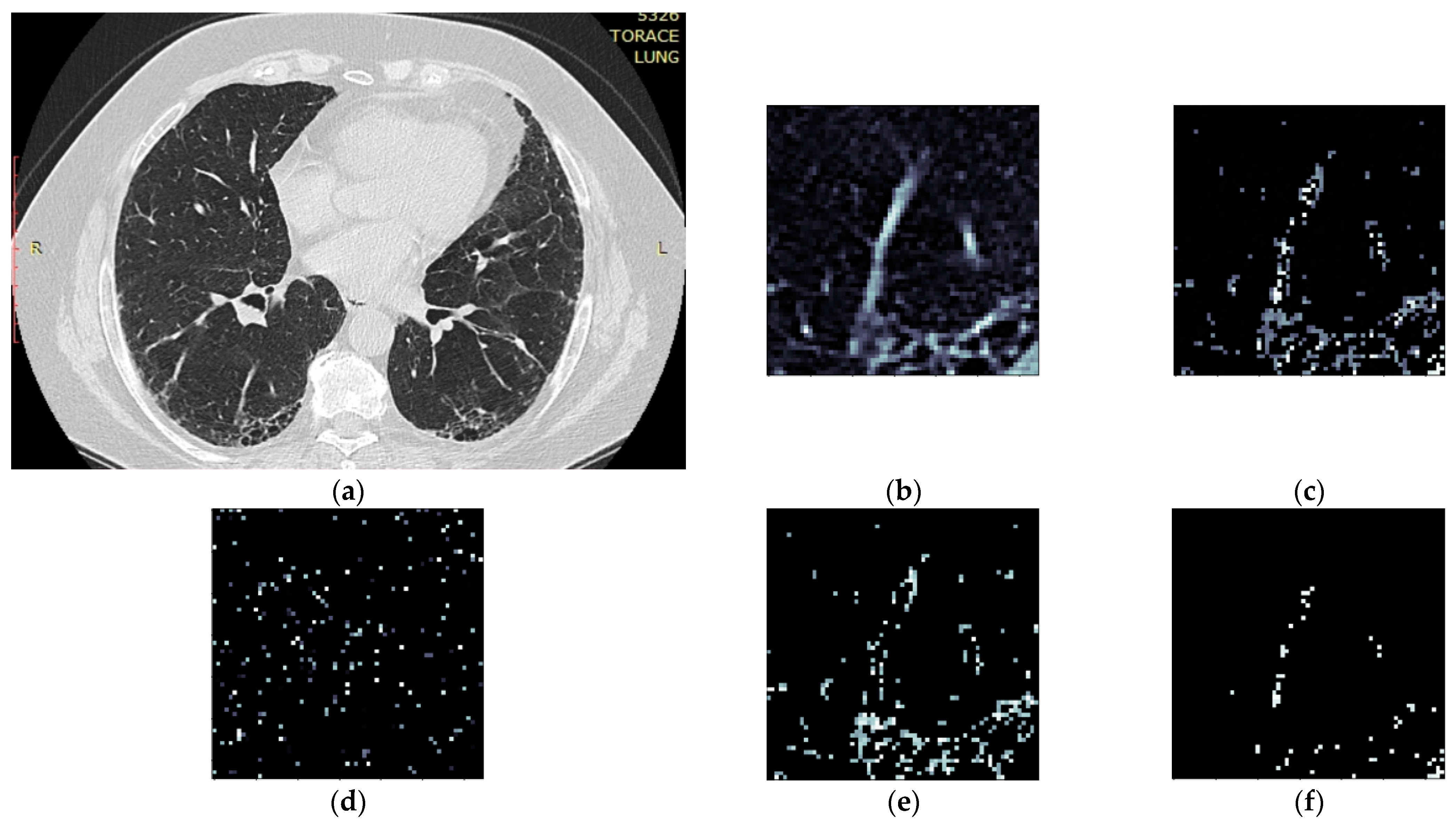
- Convert pixel gradient into a Hounsfield unit value according to the formula:where rescaleSlope and rescaleIntercept are constant values dependent on the CT equipment and embedded in the DICOM metadata, and PxGradient is the color code of a pixel;HUv = rescaleSlope * PxGradient + rescaleIntercept,
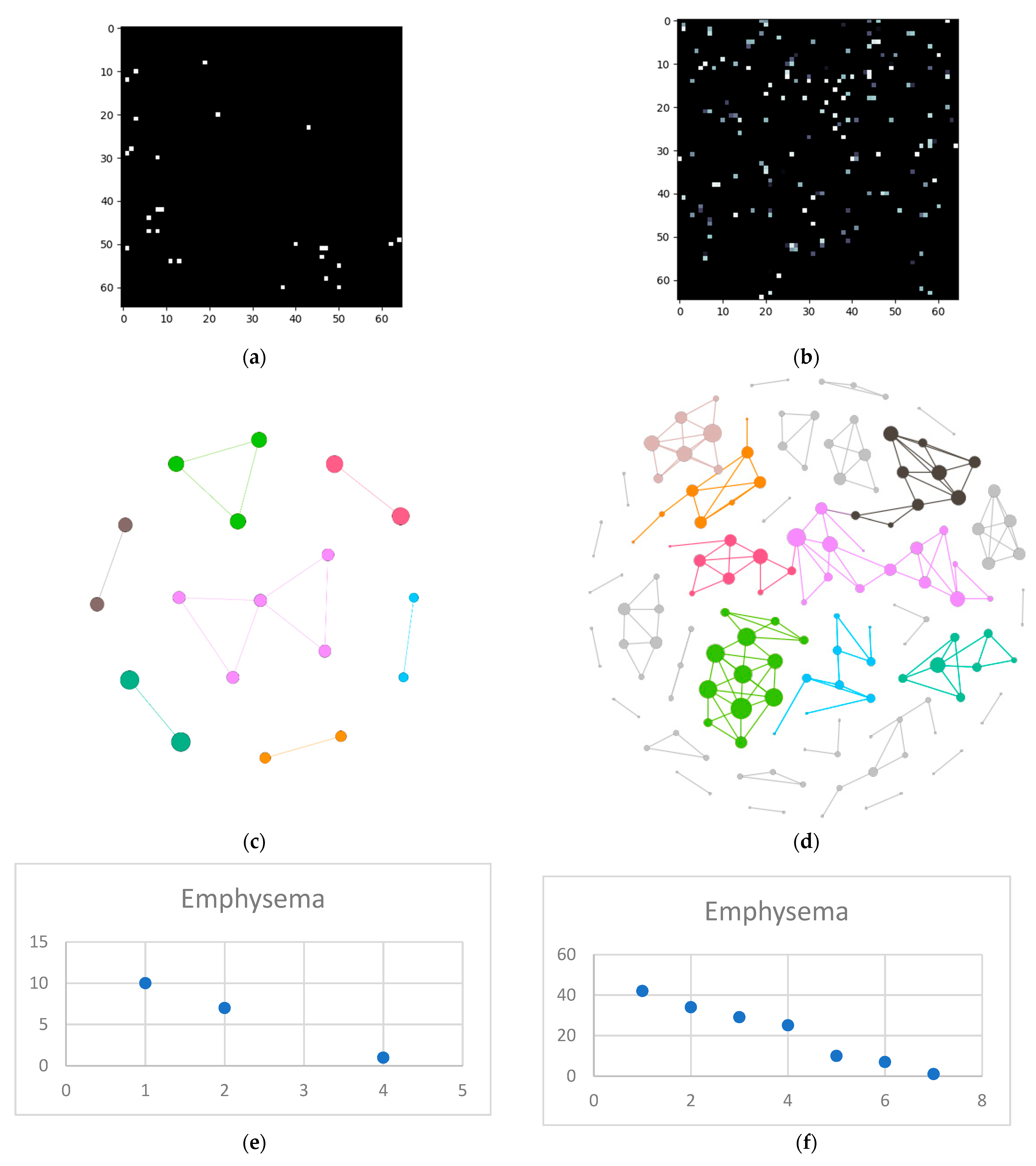
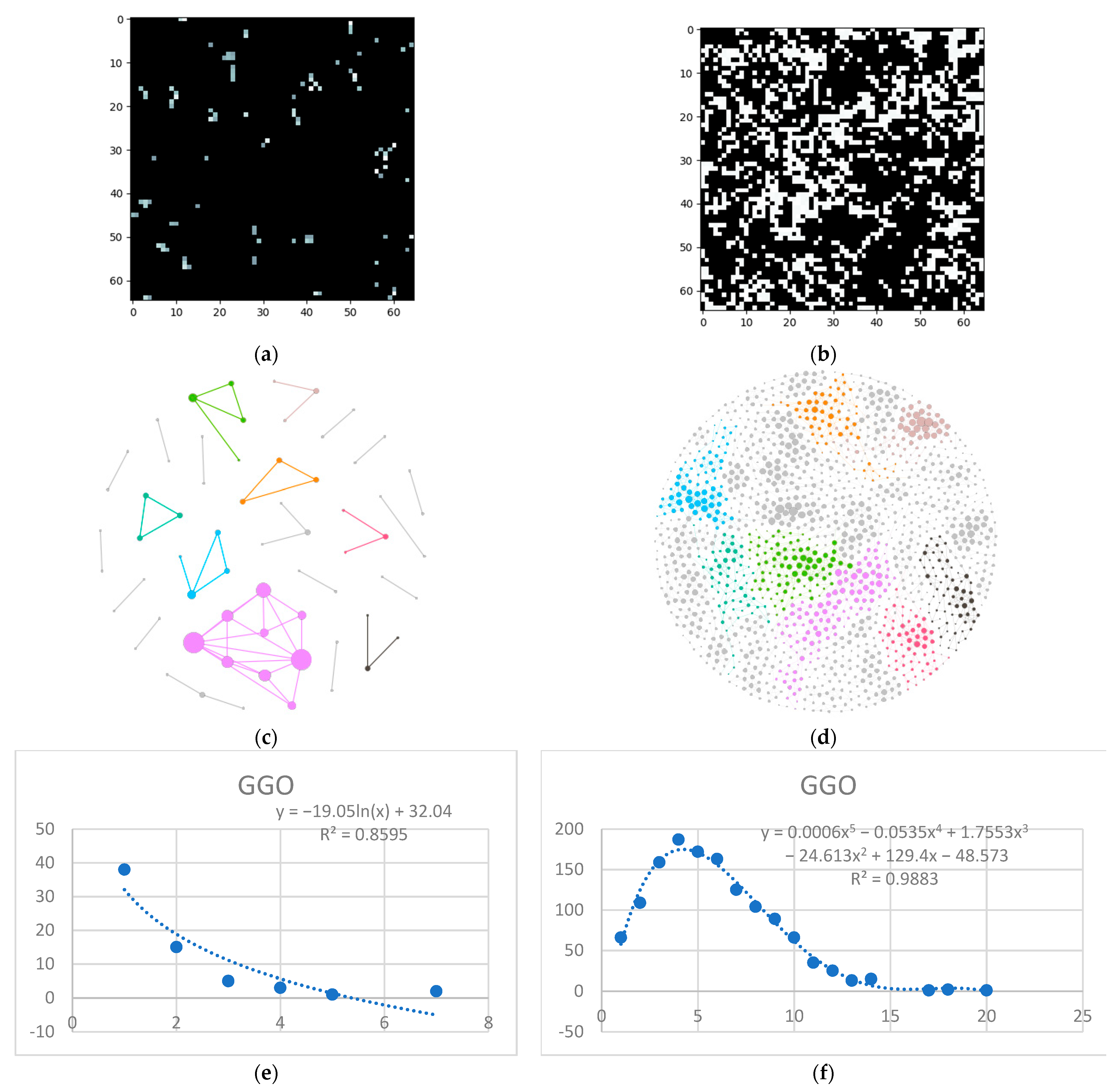
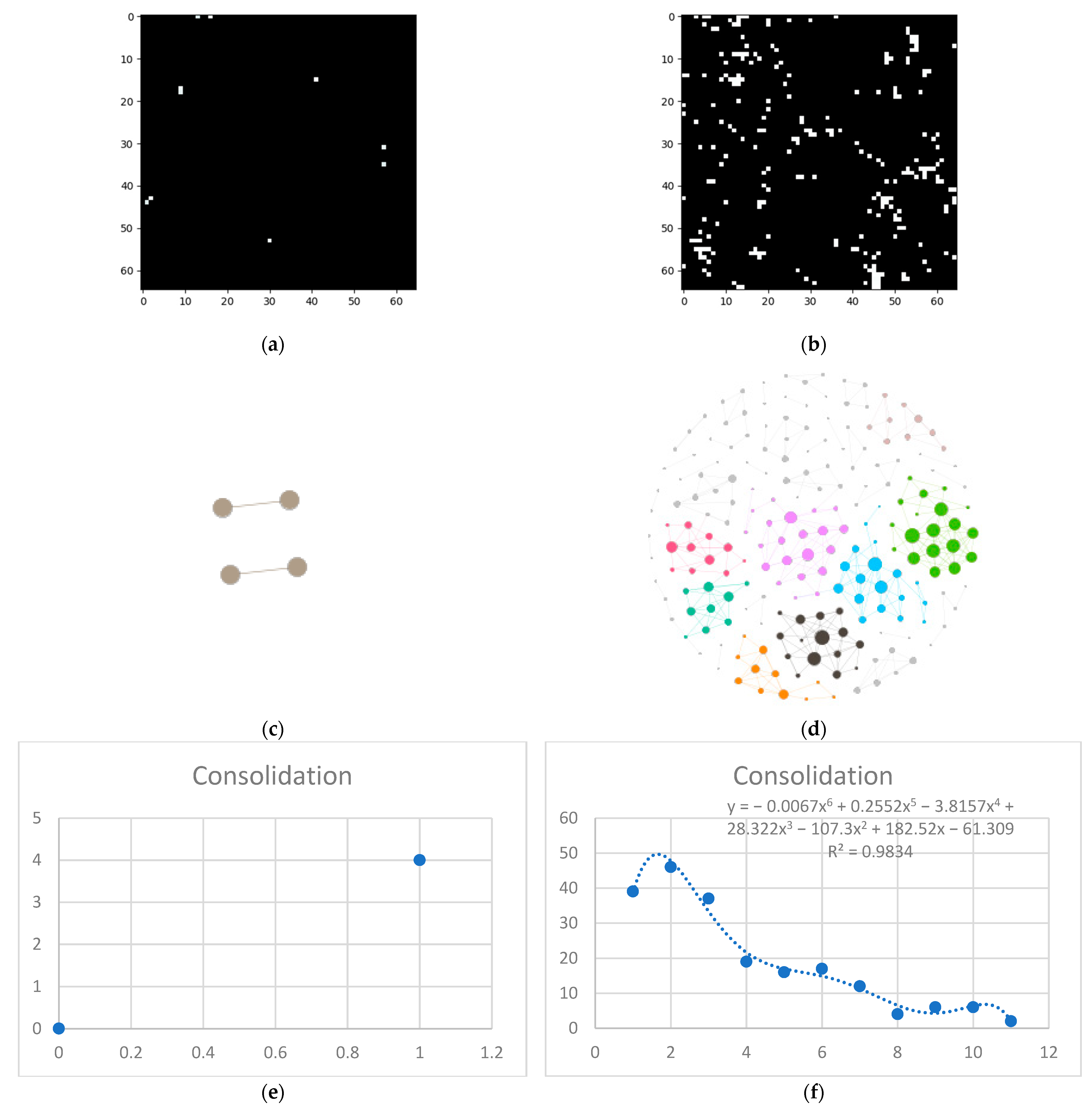
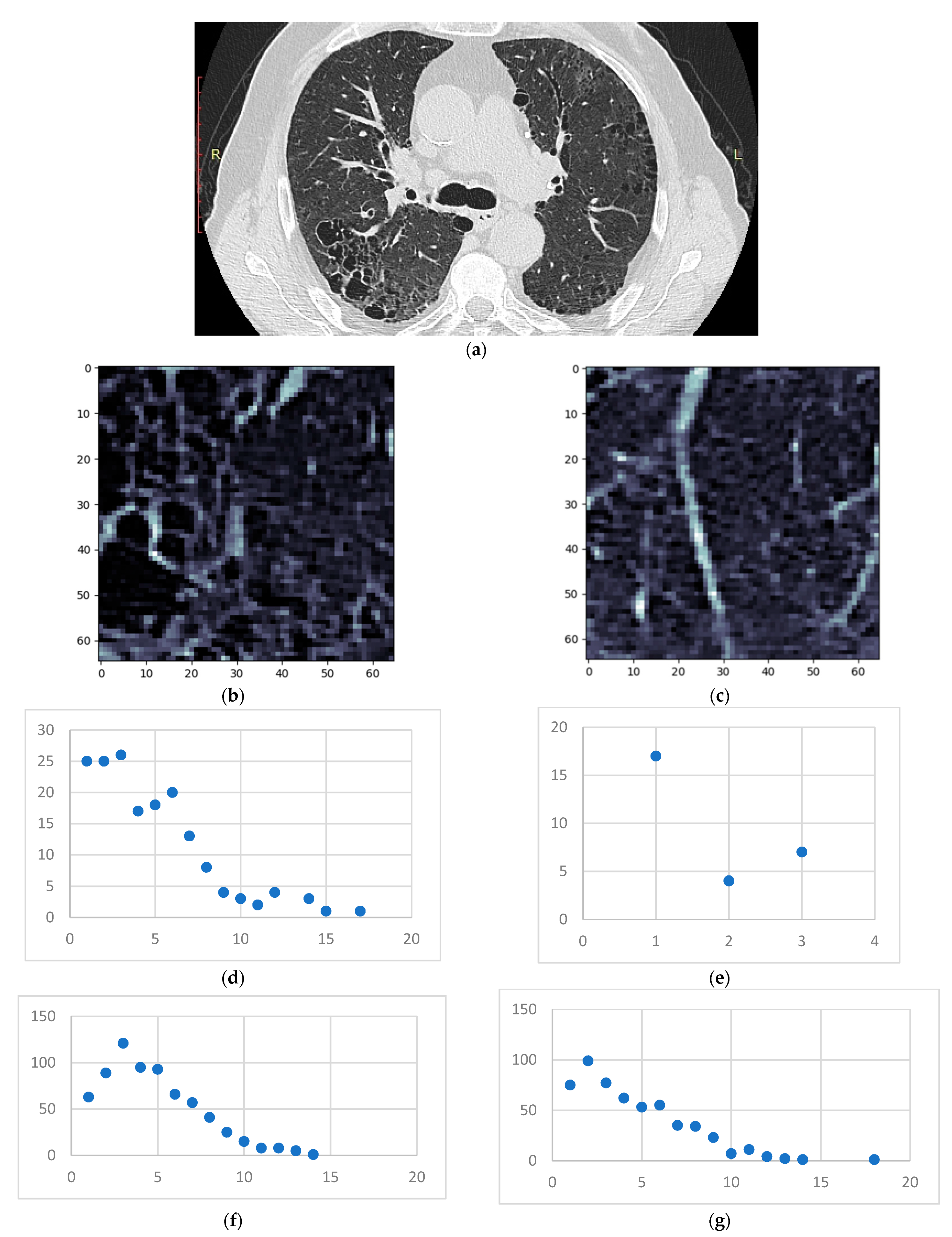
- Isolate all emphysema-like tissue, GGO (Ground Glass Opacity), and consolidation densities in the cropped image and leave out any other types of tissue (Figure 2);
- Separate each HU strip in the sample into a separate layer (Figure 2).
- Generate complex networks out of each layer;
- Analyze connectivity, closeness, and distribution of nodes (pixels);
- Determine patterns of normal lungs and affected lungs.
- Each pixel represents a network node, and the pixel color (gradient) constitutes its value;
- The two pixels are presumed to be connected if the following conditions are met:
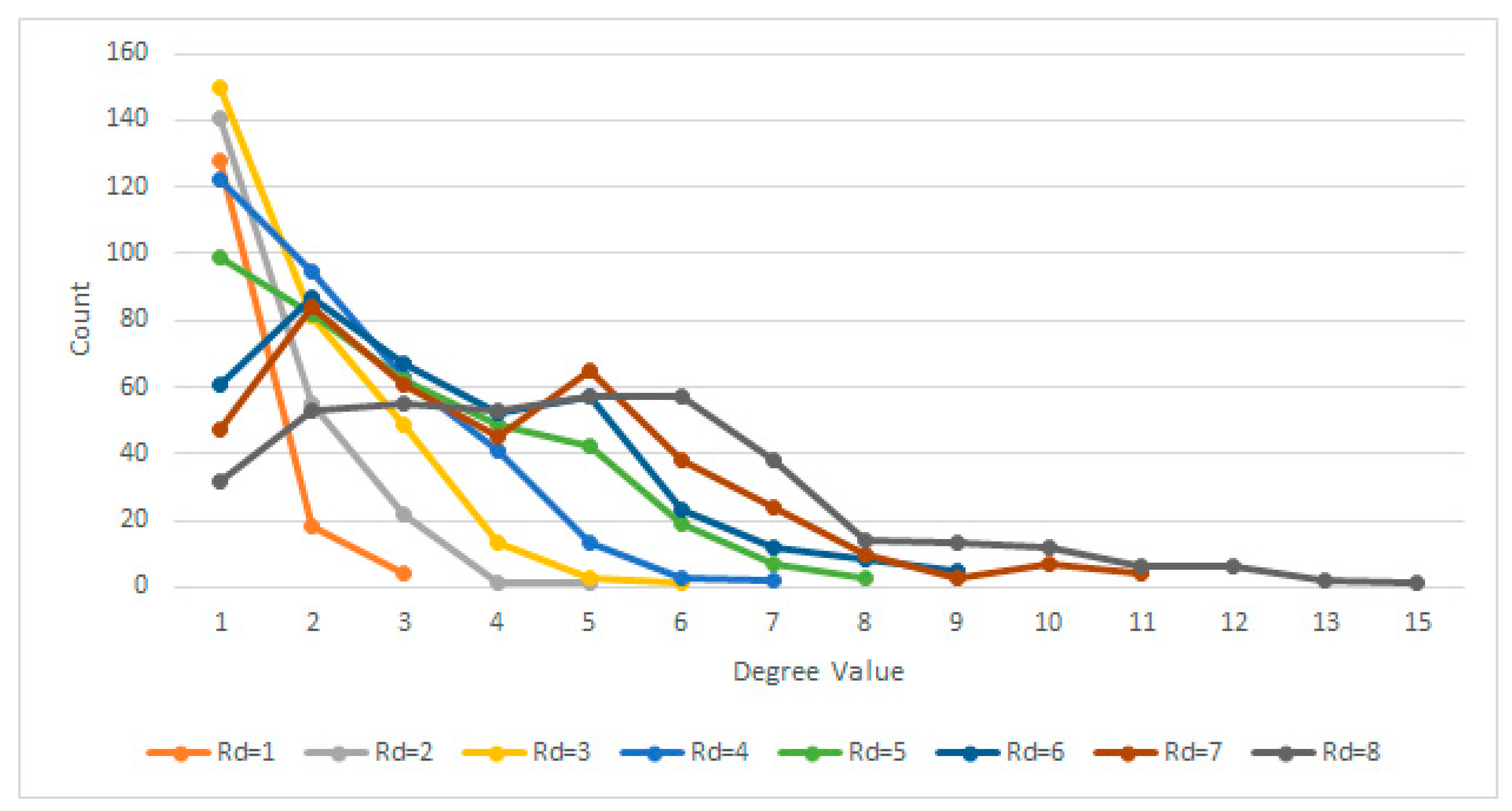
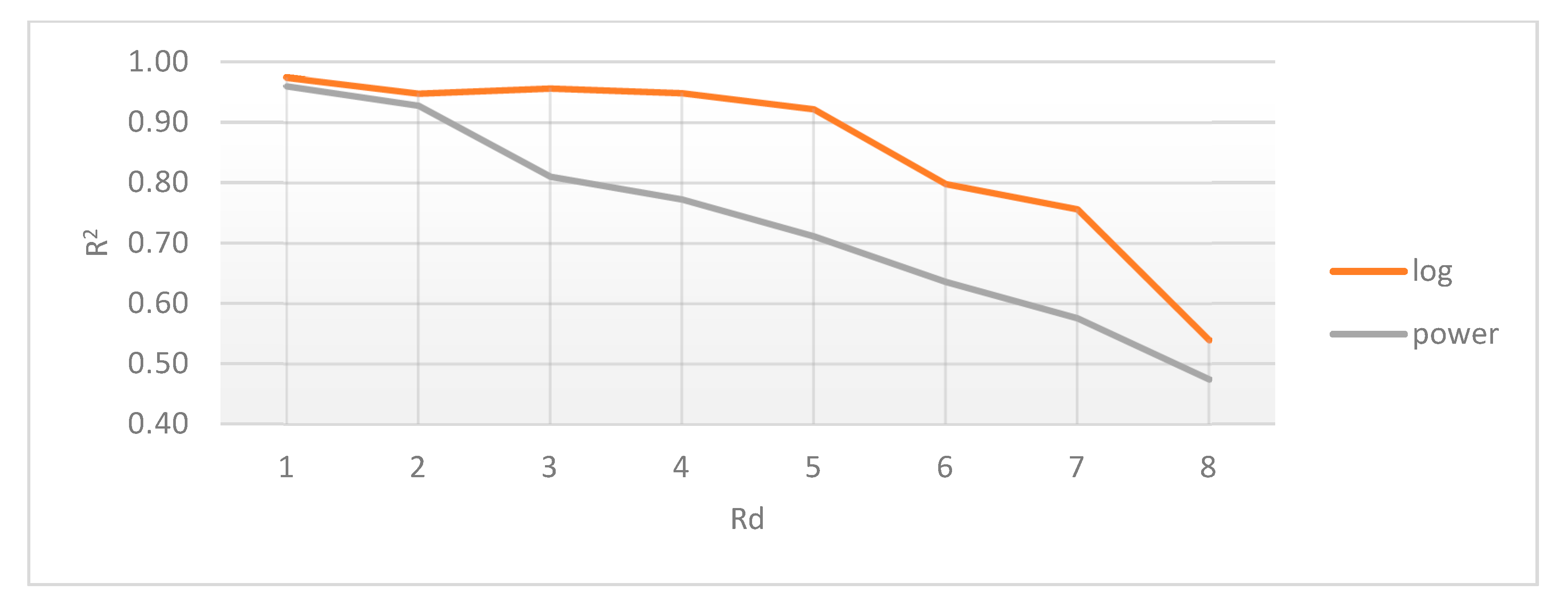
- The radial distance (Rd) between them (within the crop) is Rd ≤ 4 pixels. Assuming each pixel (Px) is the origin O of a circle with radius r = 4, every other pixel (Py) within the circle area can be considered connected. In other words: ;
- The gradient difference between Px and Py is less than or equal to 50.
2.4.1. Radial Distance Selection
2.4.2. Gradient Difference Threshold
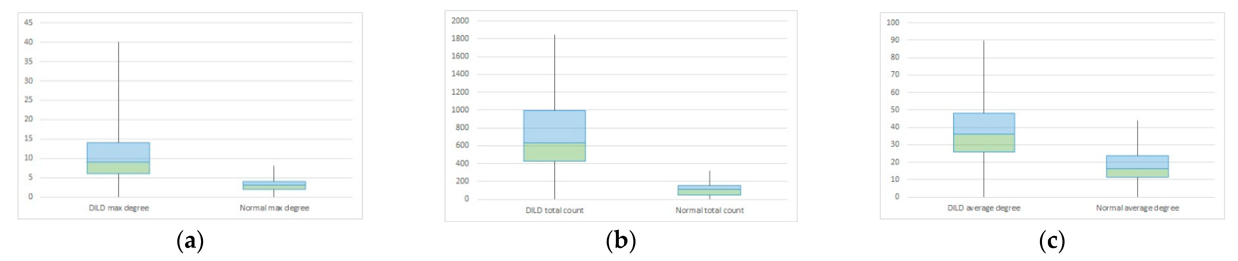
3. Results
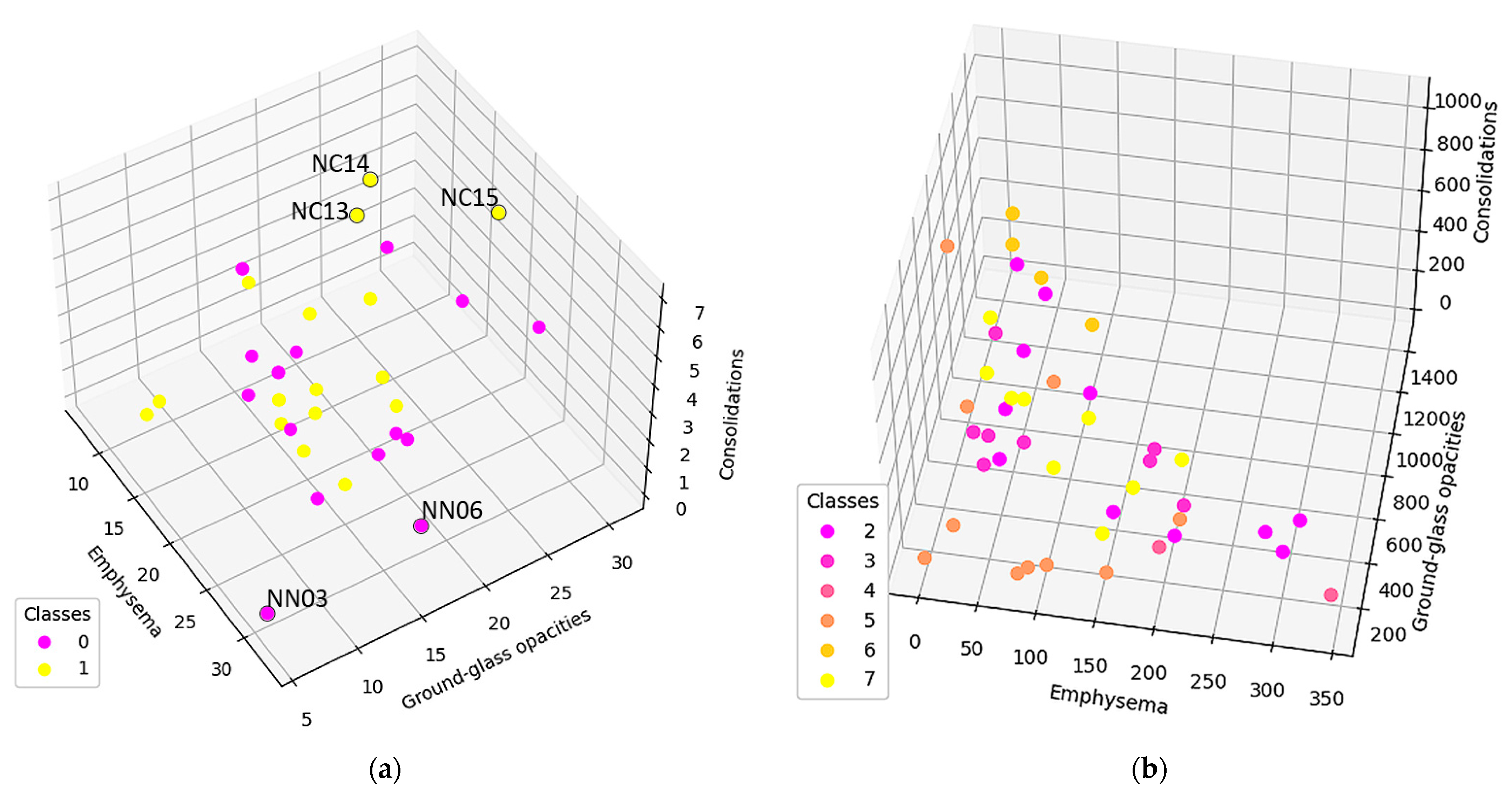
3.1. Normal and DILD Case Sample Results
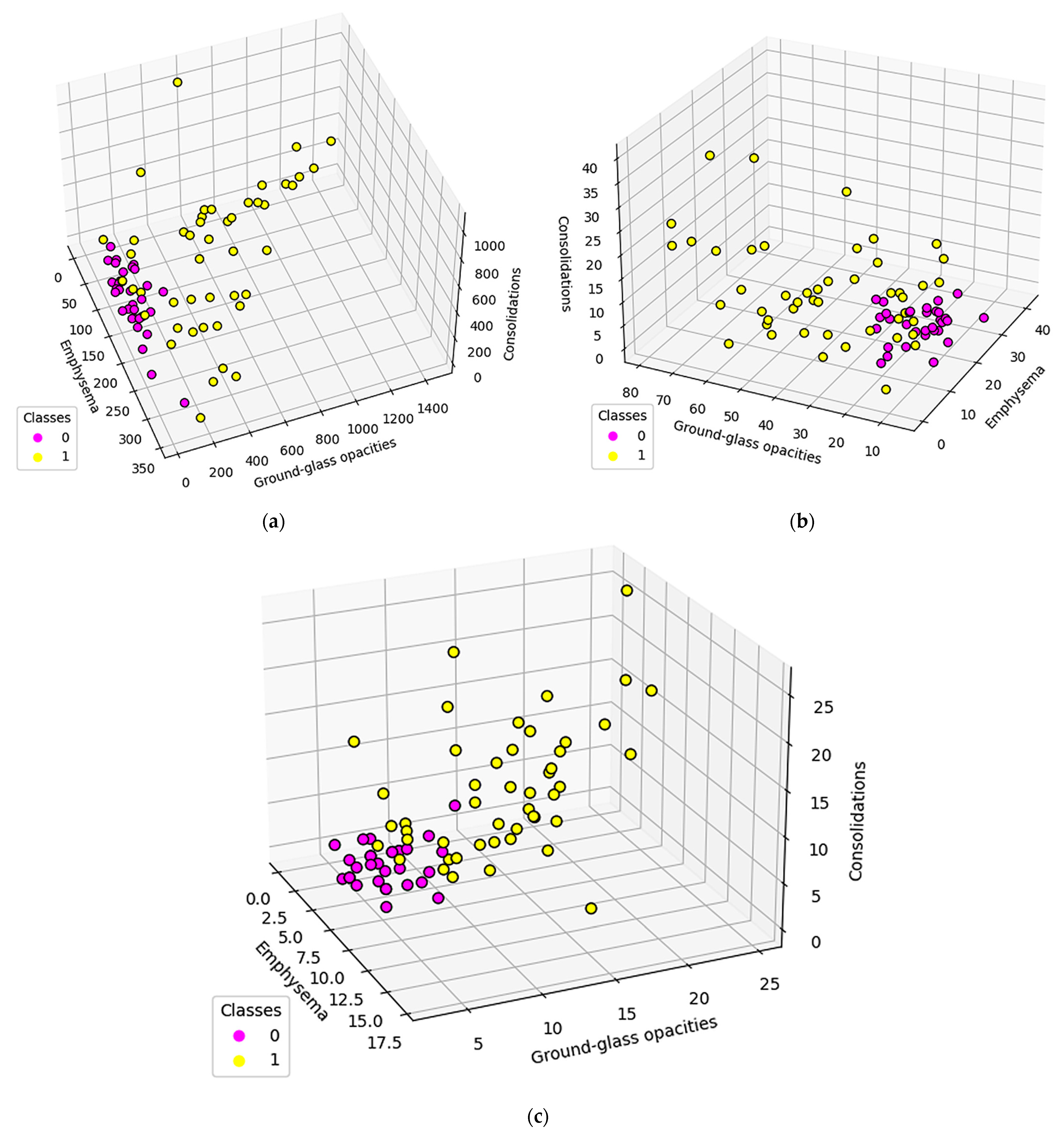
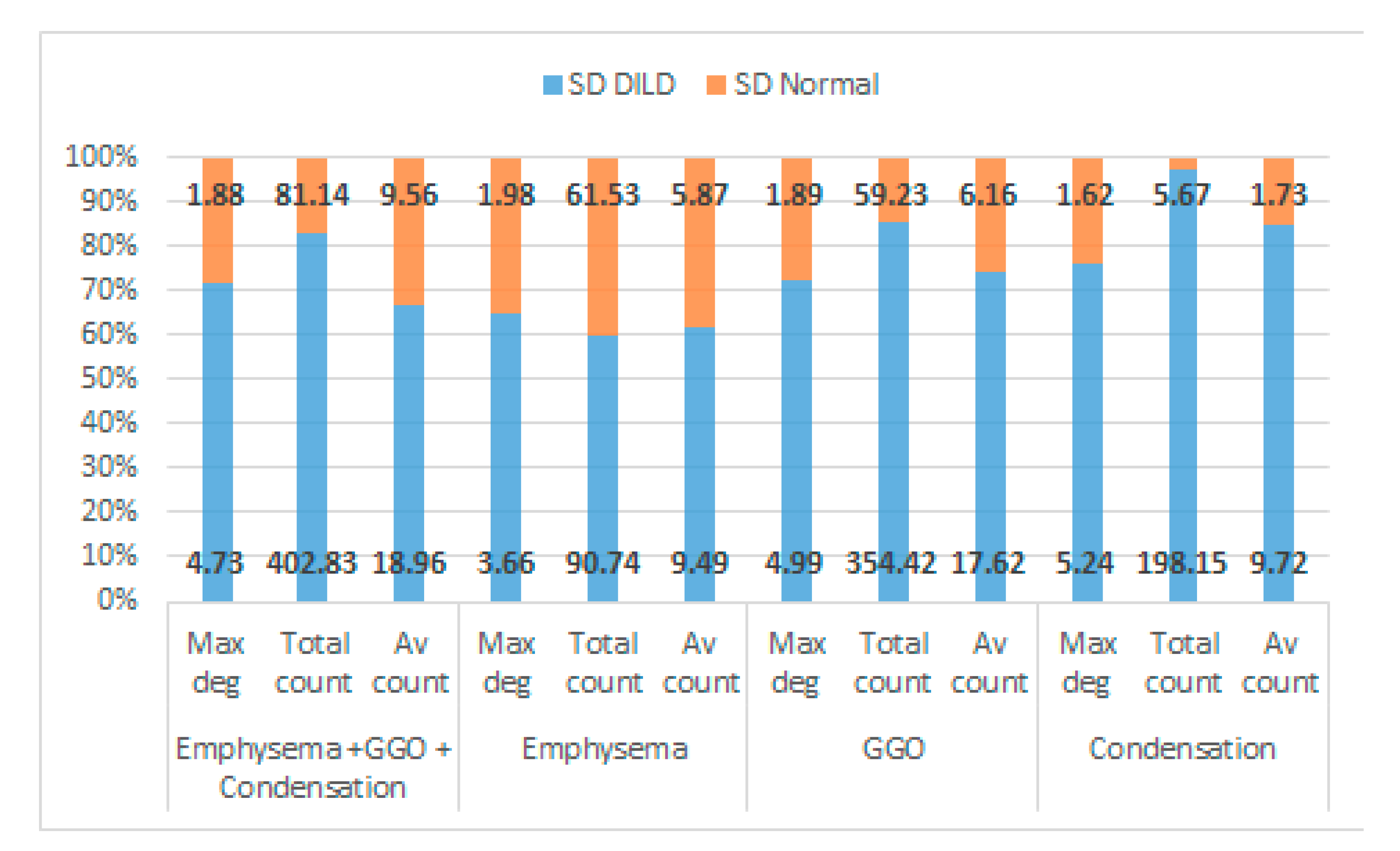
3.2. Results
4. Discussion
4.1. Network System Science
4.2. Medical Science
4.3. Comparisons with other HRCT Analysis Methods
5. Conclusions
Author Contributions
Funding
Institutional Review Board Statement
Informed Consent Statement
Data Availability Statement
Conflicts of Interest
Abbreviations
| CAD | Computer Aided Diagnosis |
| COPD | Chronic Obstructive Pulmonary Disease |
| CT | Computer Tomography |
| DILD | Diffuse interstitial lung Diseases |
| FOV | Field of View |
| GE | General Electric |
| GGO | Ground Glass Opacity |
| HRCT | High Resolution Computed Tomography |
| HPc | Chronic Hypersensitivity Pneumonitis |
| HU | Hounsfield Unit |
| ILD | Interstitial Lung Diseases |
| IPF | Idiopathic Pulmonary Fibrosis |
| NSIP | Non-Specific Interstitial Pneumonia |
| OP | Organizing Pneumonitis |
| PCR | Polymerase Chain Reaction |
| PFT | Pulmonary Function Test |
| SPL | Secondary Pulmonary Lobule |
| UIP | Usual Interstitial Pneumonia |
References
- Ryu, J.H.; Daniels, C.E.; Hartman, T.E.; Yi, E.S. Diagnosis of Interstitial Lung Diseases. Mayo Clin. Proc. 2007, 82, 976–986. [Google Scholar] [CrossRef] [PubMed] [Green Version]
- Guler, S.A.; Corte, T.J. Interstitial Lung Disease in 2020: A History of Progress. Clin. Chest Med. 2021, 42, 229–239. [Google Scholar] [CrossRef]
- Molina-Molina, M.; Aburto, M.; Acosta, O.; Ancochea, J.; Rodríguez-Portal, J.A.; Sauleda, J.; Lines, C.; Xaubet, A. Importance of early diagnosis and treatment in idiopathic pulmonary fibrosis. Expert Rev. Respir. Med. 2018, 12, 537–539. [Google Scholar] [CrossRef] [PubMed]
- Kolb, M.; Richeldi, L.; Behr, J.; Maher, T.M.; Tang, W.; Stowasser, S.; Hallmann, C.; du Bois, R.M. Nintedanib in patients with idiopathic pulmonary fibrosis and preserved lung volume. Thorax 2017, 72, 340–346. [Google Scholar] [CrossRef] [Green Version]
- Meyer, K.C. Diagnosis and management of interstitial lung disease. Transl. Respir. Med. 2014, 2, 4. [Google Scholar] [CrossRef] [PubMed] [Green Version]
- Manolescu, D.; Davidescu, L.; Traila, D.; Oancea, C.; Tudorache, V. The reliability of lung ultrasound in assessment of idiopathic pulmonary fibrosis. Clin. Interv. Aging 2018, 13, 437–449. [Google Scholar] [CrossRef] [PubMed] [Green Version]
- Sverzellati, N. Highlights of HRCT imaging in IPF. Respir. Res. 2013, 14 (Suppl. 1), S3. [Google Scholar] [CrossRef] [PubMed] [Green Version]
- de Bois, R.M. An earlier and more confident diagnosis of idiopathic pulmonary fibrosis. Eur. Respir. Rev. Off. J. Eur. Respir. Soc. 2012, 21, 141–146. [Google Scholar] [CrossRef] [PubMed]
- Inomata, M.; Jo, T.; Kuse, N.; Awano, N.; Tone, M.; Yoshimura, H.; Moriya, A.; Bae, Y.; Terada, Y.; Furuhata, Y.; et al. Clinical impact of the radiological indeterminate for usual interstitial pneumonia pattern on the diagnosis of idiopathic pulmonary fibrosis. Respir. Investig. 2021, 59, 81–89. [Google Scholar] [CrossRef]
- Walsh, S.L.F.; Calandriello, L.; Sverzellati, N.; Wells, A.U.; Hansell, D.M.; UIP Observer Consort. Interobserver agreement for the ATS/ERS/JRS/ALAT criteria for a UIP pattern on CT. Thorax 2016, 71, 45–51. [Google Scholar] [CrossRef] [PubMed] [Green Version]
- Walsh, S.L.F.; Wells, A.U.; Desai, S.R.; Poletti, V.; Piciucchi, S.; Dubini, A.; Nunes, H.; Valeyre, D.; Brillet, P.Y.; Kambouchner, M.; et al. Multicentre evaluation of multidisciplinary team meeting agreement on diagnosis in diffuse parenchymal lung disease: A case-cohort study. Lancet Respir. Med. 2016, 4, 557–565. [Google Scholar] [CrossRef] [Green Version]
- Trusculescu, A.A.; Manolescu, D.; Tudorache, E.; Oancea, C. Deep learning in interstitial lung disease-how long until daily practice. Eur. Radiol. 2020, 30, 6285–6292. [Google Scholar] [CrossRef]
- Crews, M.S.; Bartholmai, B.J.; Adegunsoye, A.; Oldham, J.M.; Montner, S.M.; Karwoski, R.A.; Husain, A.N.; Vij, R.; Noth, I.; Strek, M.E.; et al. Automated CT Analysis of Major Forms of Interstitial Lung Disease. J. Clin. Med. 2020, 9, 3776. [Google Scholar] [CrossRef] [PubMed]
- Simonyan, K.; Zisserman, A. Very Deep Convolutional Networks for Large-Scale Image Recognition. arXiv 2015, arXiv:1409.1556. [Google Scholar]
- Li, Q.; Cai, W.; Wang, X.; Zhou, Y.; Feng, D.D.; Chen, M. Medical image classification with convolutional neural network. In Proceedings of the 13th International Conference on Control Automation Robotics Vision (ICARCV), Singapore, 10–12 December 2014; pp. 844–848. [Google Scholar] [CrossRef]
- Walsh, S.L.F.; Calandriello, L.; Silva, M.; Sverzellati, N. Deep learning for classifying fibrotic lung disease on high-resolution computed tomography: A case-cohort study. Lancet Respir. Med. 2018, 6, 837–845. [Google Scholar] [CrossRef]
- Li, Q.; Cai, W.; Feng, D.D. Lung image patch classification with automatic feature learning. In Proceedings of the 2013 35th Annual International Conference of the IEEE Engineering in Medicine and Biology Society (EMBC), Osaka, Japan, 3–7 July 2013; pp. 6079–6082. [Google Scholar] [CrossRef]
- Walsh, S.L.F.; Kolb, M. Radiological diagnosis of interstitial lung disease: Is it all about pattern recognition? Eur. Respir. J. 2018, 52, 1801321. [Google Scholar] [CrossRef] [PubMed]
- Signs and Patterns of Lung Disease—Chest Radiology: The Essentials, 2nd ed.; Available online: https://doctorlib.info/medical/chest/2.html (accessed on 6 February 2022).
- Hobbs, S.; Chung, J.H.; Leb, J.; Kaproth-Joslin, K.; Lynch, D.A. Practical Imaging Interpretation in Patients Suspected of Having Idiopathic Pulmonary Fibrosis: Official Recommendations from the Radiology Working Group of the Pulmonary Fibrosis Foundation. Radiol. Cardiothorac. Imaging 2021, 3, e200279. [Google Scholar] [CrossRef]
- Chen, A.; Karwoski, R.A.; Gierada, D.S.; Bartholmai, B.J.; Koo, C.W. Quantitative CT Analysis of Diffuse Lung Disease. RadioGraphics 2020, 40, 28–43. [Google Scholar] [CrossRef]
- Zrimec, T.; Busayarat, S. Computer-aided Analysis and Interpretation of HRCT Images of the Lung. In Theory and Applications of CT Imaging and Analysis; In-Tech: Rijeka, Croatia, 2011. [Google Scholar] [CrossRef] [Green Version]
- Depeursinge, A.; Zrimec, T.; Busayarat, S.; Müller, H. 3D Lung Image Retrieval Using Localized Features. In Proceedings of the Medical Imaging 2011: Computer-Aided Diagnosis, Lake Buena Vista, FL, USA, 9 March 2011; Volume 7963, pp. 701–714. [Google Scholar] [CrossRef]
- de Lima, G.V.L.; Castilho, T.R.; Bugatti, P.H.; Saito, P.T.M.; Lopes, F.M. A Complex Network-Based Approach to the Analysis and Classification of Images. In Progress in Pattern Recognition, Image Analysis, Computer Vision, and Applications; Springer International Publishing: Cham, Switzerland, 2015; pp. 322–330. [Google Scholar] [CrossRef]
- Mourchid, Y.; Hassouni, M.E.; Cherifi, H. A General Framework for Complex Network-Based Image Segmentation. Multimed. Tools Appl. 2019, 78, 20191–20216. [Google Scholar] [CrossRef] [Green Version]
- Li, L.; Qin, L.; Xu, Z.; Yin, Y.; Wang, X.; Kong, B.; Bai, J.; Lu, Y.; Fang, Z.; Song, Q.; et al. Using Artificial Intelligence to Detect COVID-19 and Community-acquired Pneumonia Based on Pulmonary CT: Evaluation of the Diagnostic Accuracy. Radiology 2020, 296, E65–E71. [Google Scholar] [CrossRef]
- Belfiore, M.P.; Urraro, F.; Grassi, R.; Giacobbe, G.; Patelli, G.; Cappabianca, S.; Reginelli, A. Artificial intelligence to codify lung CT in COVID-19 patients. Radiol. Med. 2020, 125, 500–504. [Google Scholar] [CrossRef] [PubMed]
- Grassi, R.; Belfiore, M.P.; Montanelli, A.; Patelli, G.; Urraro, F.; Giacobbe, G.; Fusco, R.; Granata, V.; Petrillo, A.; Sacco, P.; et al. COVID-19 pneumonia: Computer-aided quantification of healthy lung parenchyma, emphysema, ground glass and consolidation on chest computed tomography (CT). Radiol. Med. 2021, 126, 553–560. [Google Scholar] [CrossRef] [PubMed]
- Hiramatsu, M.; Inagaki, T.; Inagaki, T.; Matsui, Y.; Satoh, Y.; Okumura, S.; Ishikawa, Y.; Miyaoka, E.; Nakagawa, K. Pulmonary ground-glass opacity (GGO) lesions-large size and a history of lung cancer are risk factors for growth. J. Thorac. Oncol. Off. Publ. Int. Assoc. Study Lung Cancer 2008, 3, 1245–1250. [Google Scholar] [CrossRef] [PubMed] [Green Version]
- Smith, K.M. Explaining the emergence of complex networks through log-normal fitness in a Euclidean node similarity space. Sci. Rep. 2021, 11, 1976. [Google Scholar] [CrossRef]
- Adler, M.; Mayo, A.; Alon, U. Logarithmic and Power Law Input-Output Relations in Sensory Systems with Fold-Change Detection. PLoS Comput. Biol. 2014, 10, e1003781. [Google Scholar] [CrossRef] [PubMed]
- Shang, Y. Degree distribution dynamics for disease spreading with individual awareness. J. Syst. Sci. Complex. 2015, 28, 96–104. [Google Scholar] [CrossRef]
- Pastor-Satorras, R.; Castellano, C.; Van Mieghem, P.; Vespignani, A. Epidemic processes in complex networks. Rev. Mod. Phys. 2015, 87, 925–979. [Google Scholar] [CrossRef] [Green Version]
- Hovinga, M.; Sprengers, R.; Kauczor, H.-U.; Schaefer-Prokop, C. CT Imaging of Interstitial Lung Diseases. Multidetector-Row CT Thorax 2016, 27, 105–130. [Google Scholar] [CrossRef]
- Desai, S.R.; Prosch, H.; Galvin, J.R. Plain Film and HRCT Diagnosis of Interstitial Lung Disease. In Diseases of the Chest, Breast, Heart and Vessels 2019-2022: Diagnostic and Interventional Imaging; Hodler, J., Kubik-Huch, R.A., von Schulthess, G.K., Eds.; Springer: Cham, Switzerland, 2019. Available online: http://www.ncbi.nlm.nih.gov/books/NBK553872/ (accessed on 6 February 2022).

| Pulmonary Zones | HU Intervals |
|---|---|
| Emphysema | [−1024, −977) |
| Normal pulmonary parenchyma | [−977, −703) |
| Ground-glass opacities | [−703, −368) |
| Others (crazy-paving, pleural fat) | [−368, −100) |
| Consolidations | [−100, 5) |
| Others (interstitial vessels) | >5 HU |
| Maximum Degree | Total Count | Average Count | ||||
|---|---|---|---|---|---|---|
| DILD | Normal | DILD | Normal | DILD | Normal | |
| Mean | 15.96875 | 7.032258 | 846.5692 | 7.1 | 51.65253 | 32.53397 |
| Variance | 39.45933 | 3.365591 | 206,084.5 | 3.334483 | 362.9068 | 113.4483 |
| Observations | 30 | 30 | 30 | 30 | 30 | 30 |
| Hypothesized Mean Difference | 0 | 0 | 0 | |||
| Df | 82 | 64 | 92 | |||
| t Stat | 10.49451 | 14.9084 | 6.288591 | |||
| P(T ≤ t) one-tail | 3.97 × 10⁻¹⁷ | 8.52 × 10⁻²³ | 5.31 × 10⁻⁹ | |||
| t Critical one-tail | 1.663649 | 1.669013 | 1.661585 | |||
| P(T ≤ t) two-tail | 7.93 × 10⁻¹⁷ | 1.7 × 10⁻²² | 1.06 × 10⁻⁸ | |||
| t Critical two-tail | 1.989319 | 1.99773 | 1.986086 | |||
Publisher’s Note: MDPI stays neutral with regard to jurisdictional claims in published maps and institutional affiliations. |
© 2022 by the authors. Licensee MDPI, Basel, Switzerland. This article is an open access article distributed under the terms and conditions of the Creative Commons Attribution (CC BY) license (https://creativecommons.org/licenses/by/4.0/).
Share and Cite
Broască, L.; Trușculescu, A.A.; Ancușa, V.M.; Ciocârlie, H.; Oancea, C.-I.; Stoicescu, E.-R.; Manolescu, D.L. A Novel Method for Lung Image Processing Using Complex Networks. Tomography 2022, 8, 1928-1946. https://doi.org/10.3390/tomography8040162
Broască L, Trușculescu AA, Ancușa VM, Ciocârlie H, Oancea C-I, Stoicescu E-R, Manolescu DL. A Novel Method for Lung Image Processing Using Complex Networks. Tomography. 2022; 8(4):1928-1946. https://doi.org/10.3390/tomography8040162
Chicago/Turabian StyleBroască, Laura, Ana Adriana Trușculescu, Versavia Maria Ancușa, Horia Ciocârlie, Cristian-Iulian Oancea, Emil-Robert Stoicescu, and Diana Luminița Manolescu. 2022. "A Novel Method for Lung Image Processing Using Complex Networks" Tomography 8, no. 4: 1928-1946. https://doi.org/10.3390/tomography8040162
APA StyleBroască, L., Trușculescu, A. A., Ancușa, V. M., Ciocârlie, H., Oancea, C.-I., Stoicescu, E.-R., & Manolescu, D. L. (2022). A Novel Method for Lung Image Processing Using Complex Networks. Tomography, 8(4), 1928-1946. https://doi.org/10.3390/tomography8040162