
Mechanical Performance Comparison of Sandwich Panels with Graded Lattice and Honeycomb Cores

 ,
,  ,
,  ,
,  ,
,  ,
, 
Abstract
1. Introduction
2. Theory and Modeling Approach
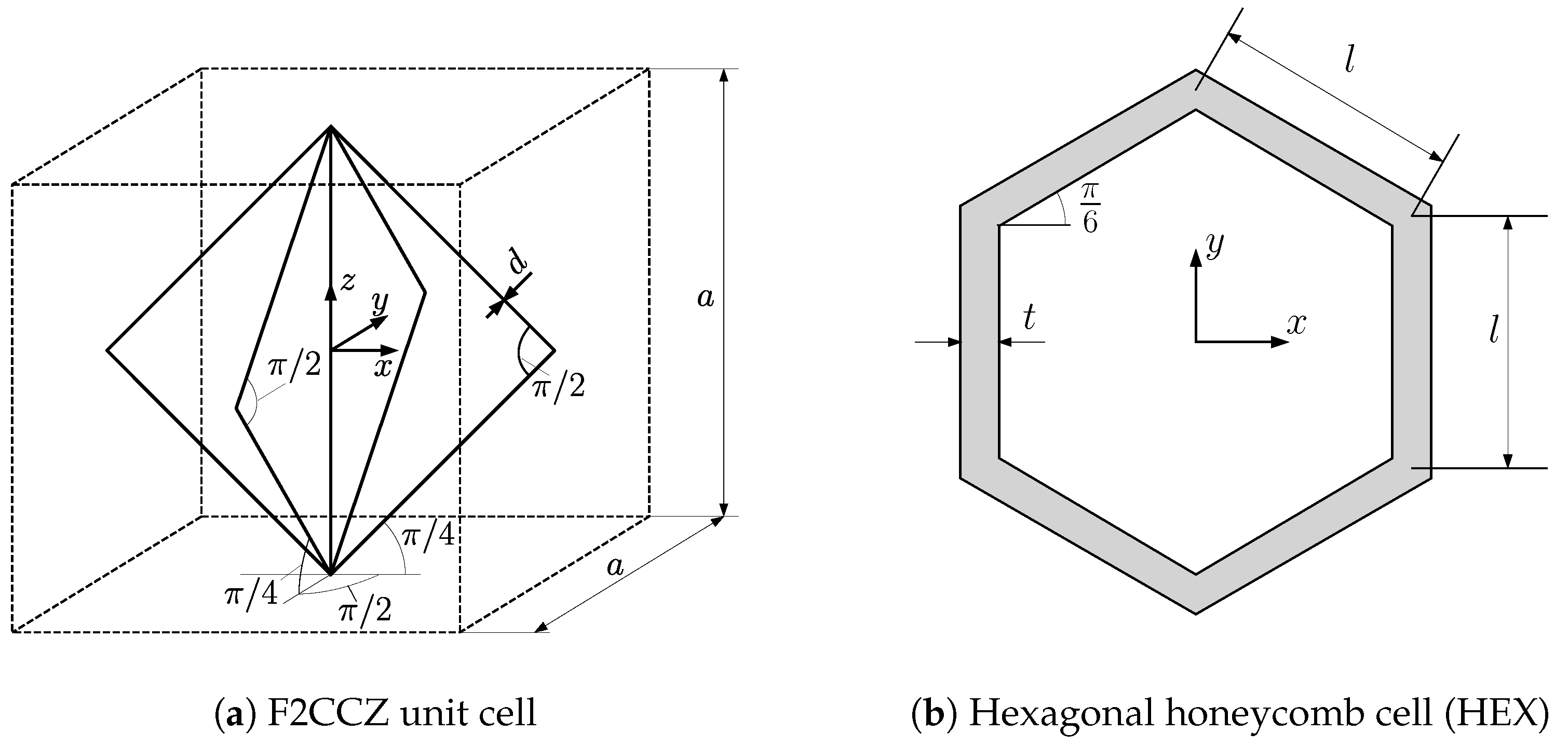
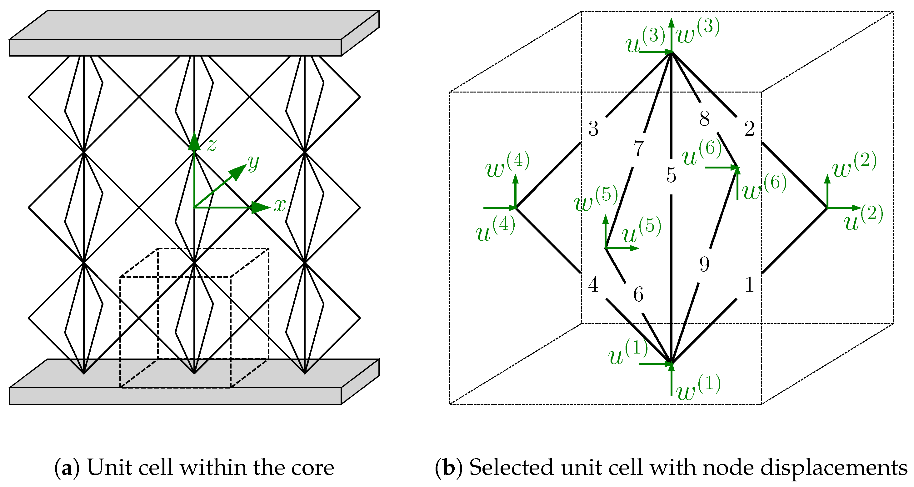
2.1. Core Materials
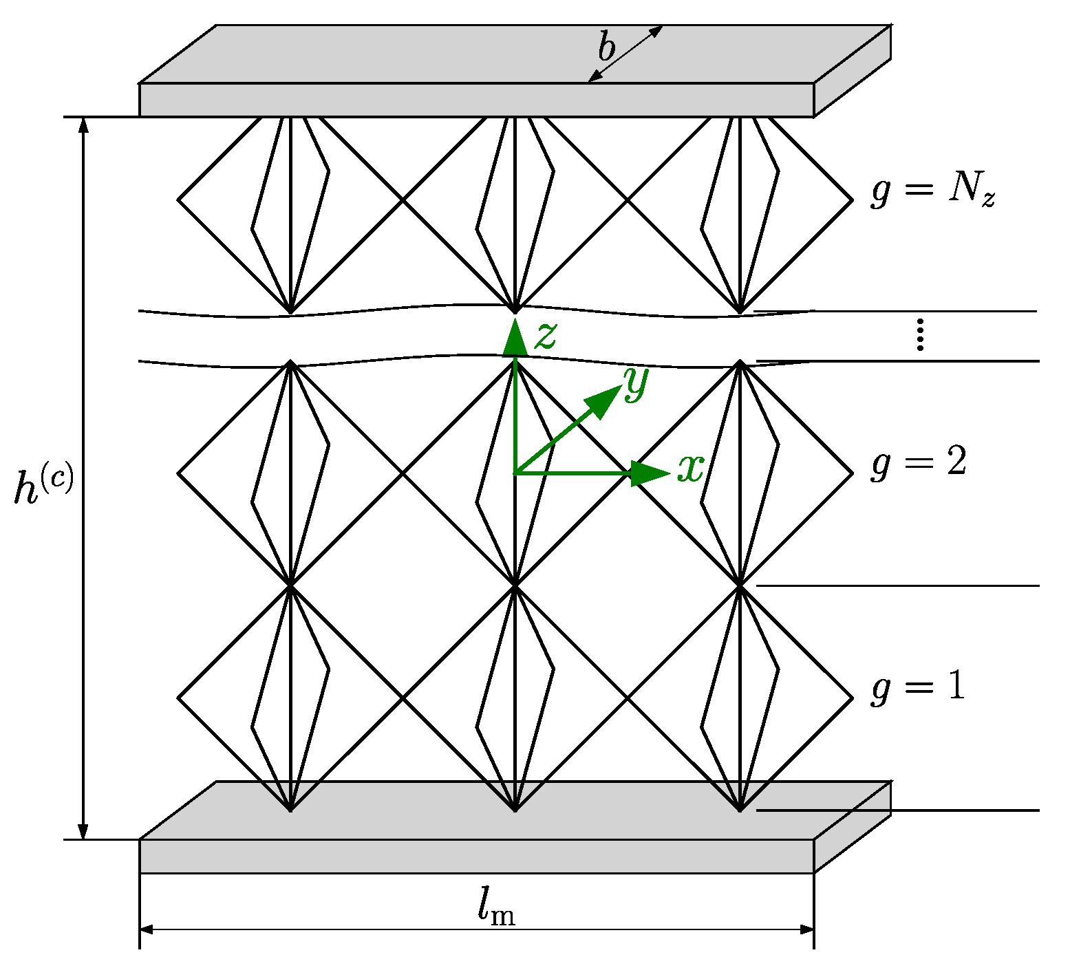
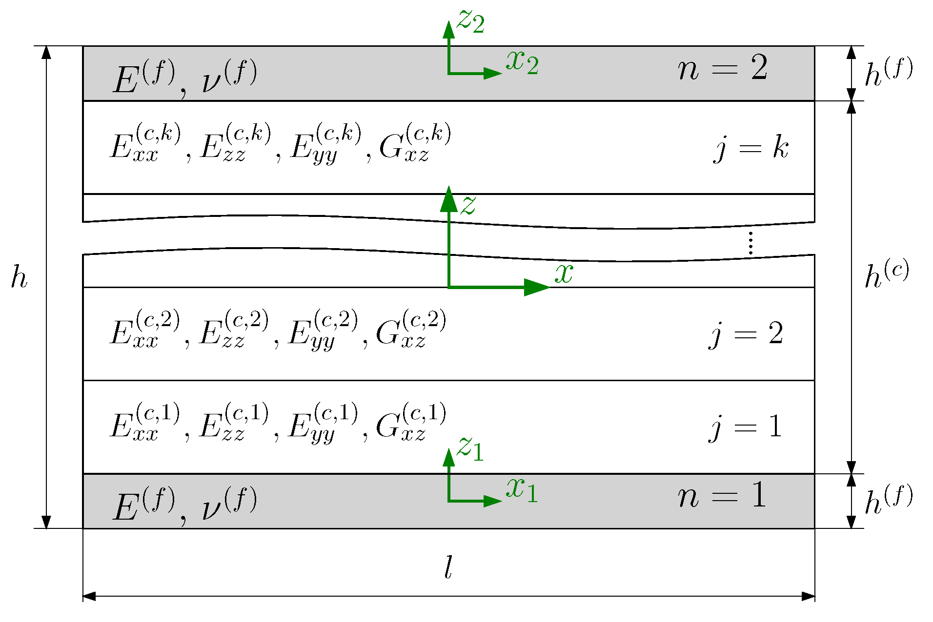
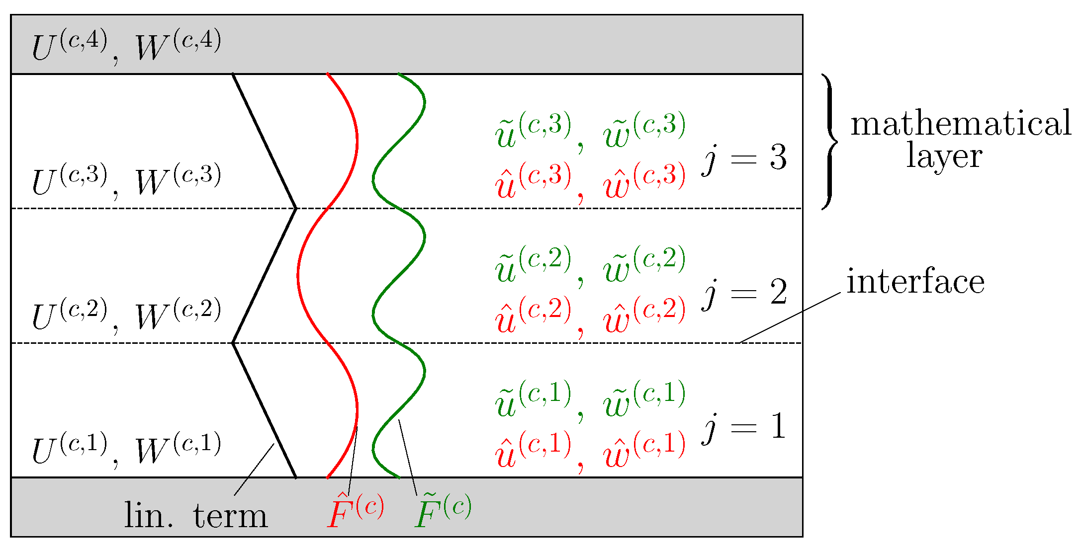
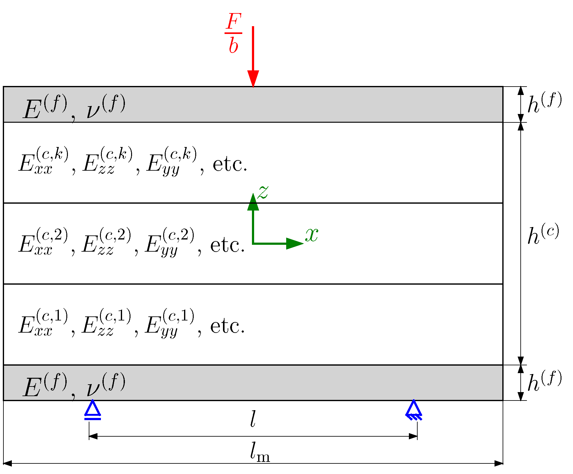
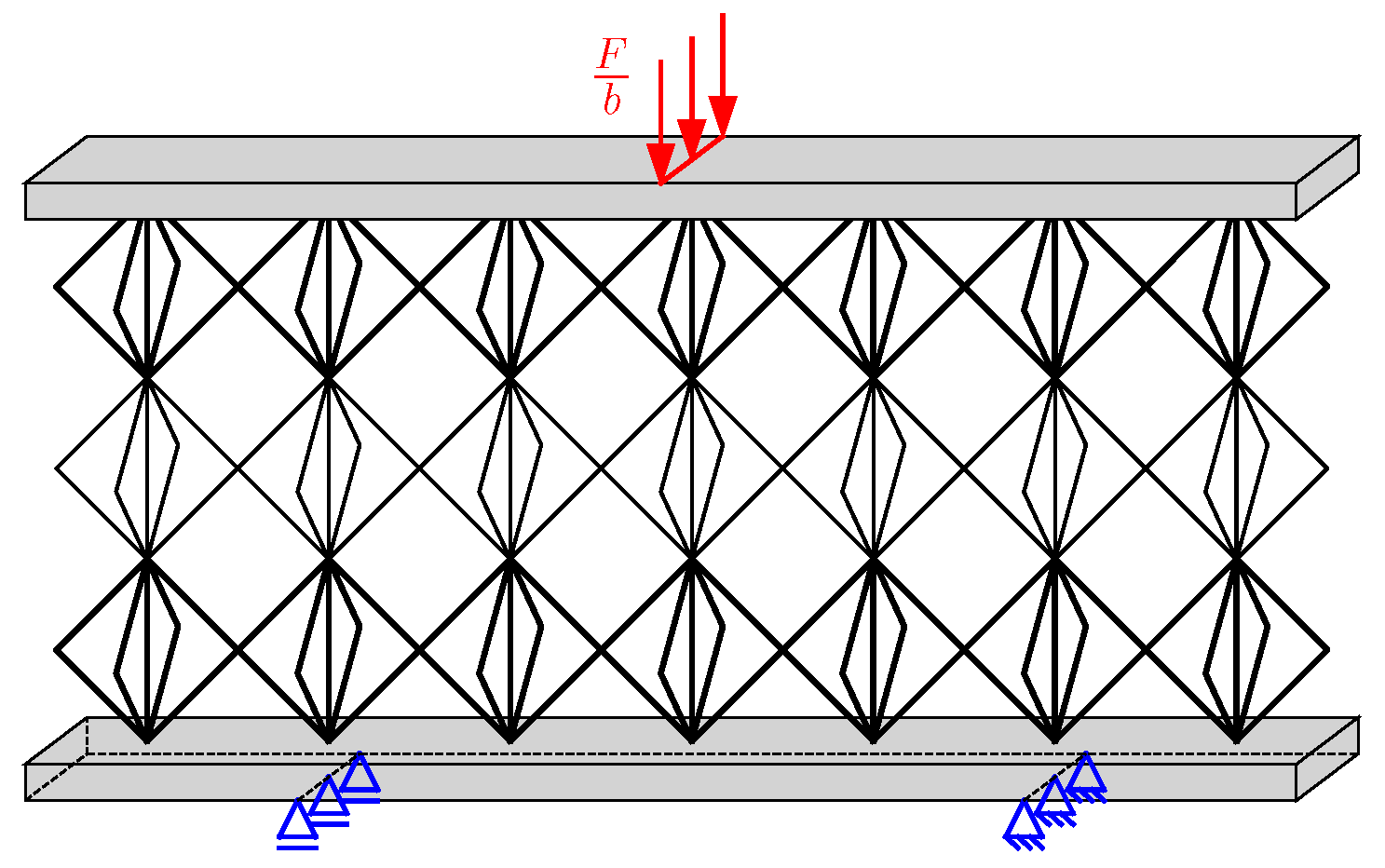
2.2. Sandwich Model
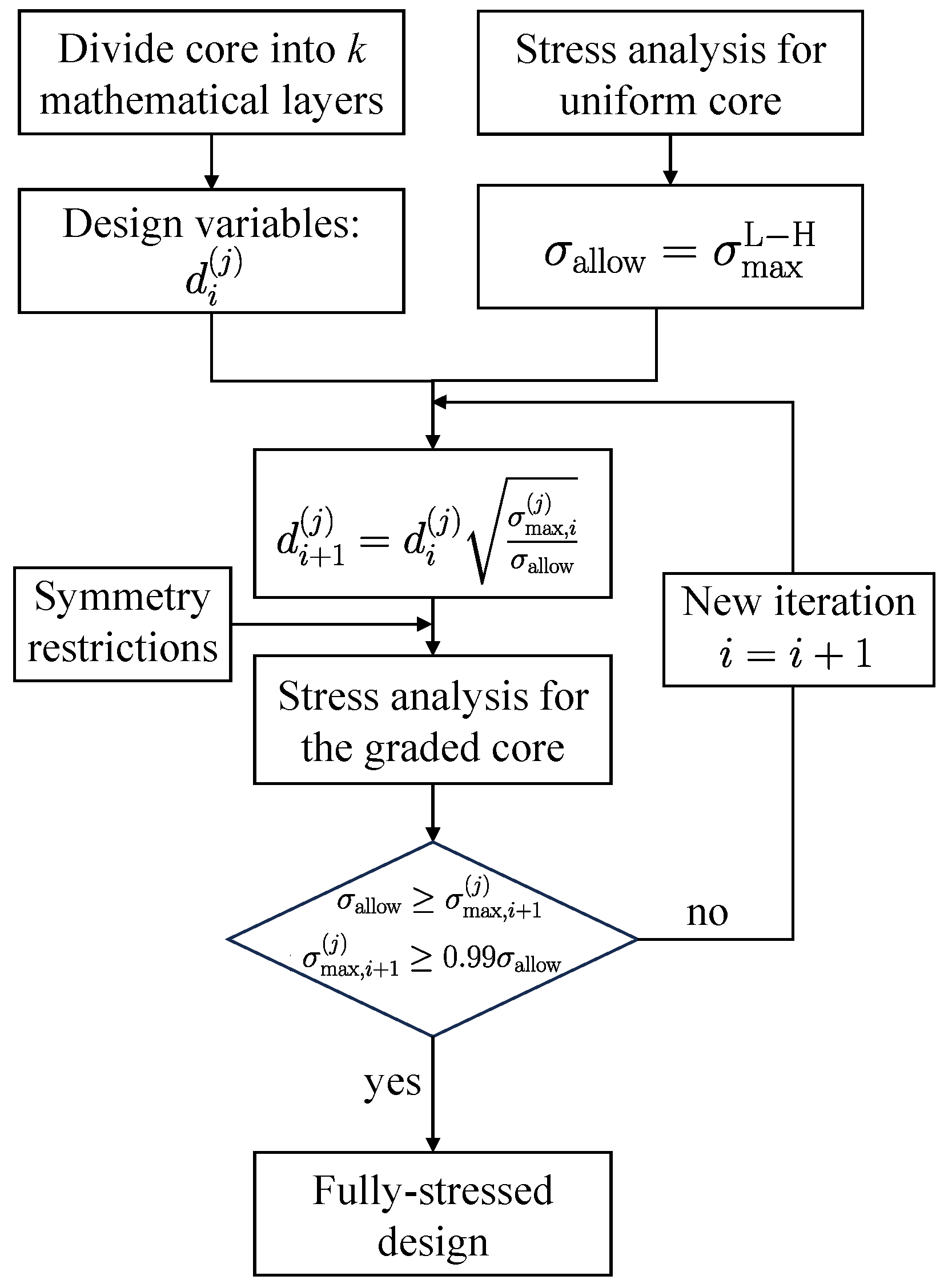
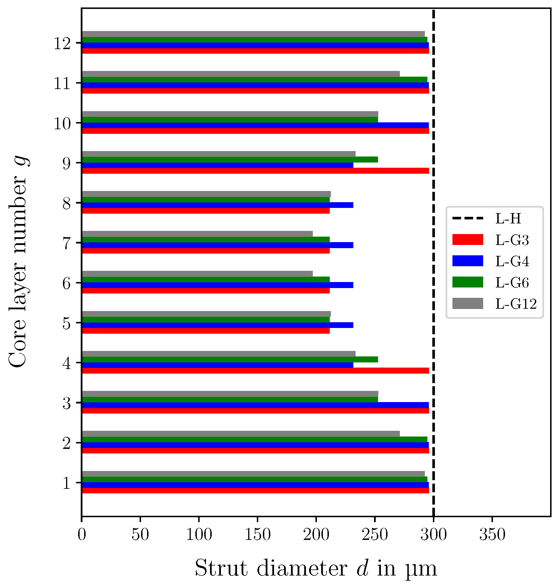
2.3. Fully Stressed Design
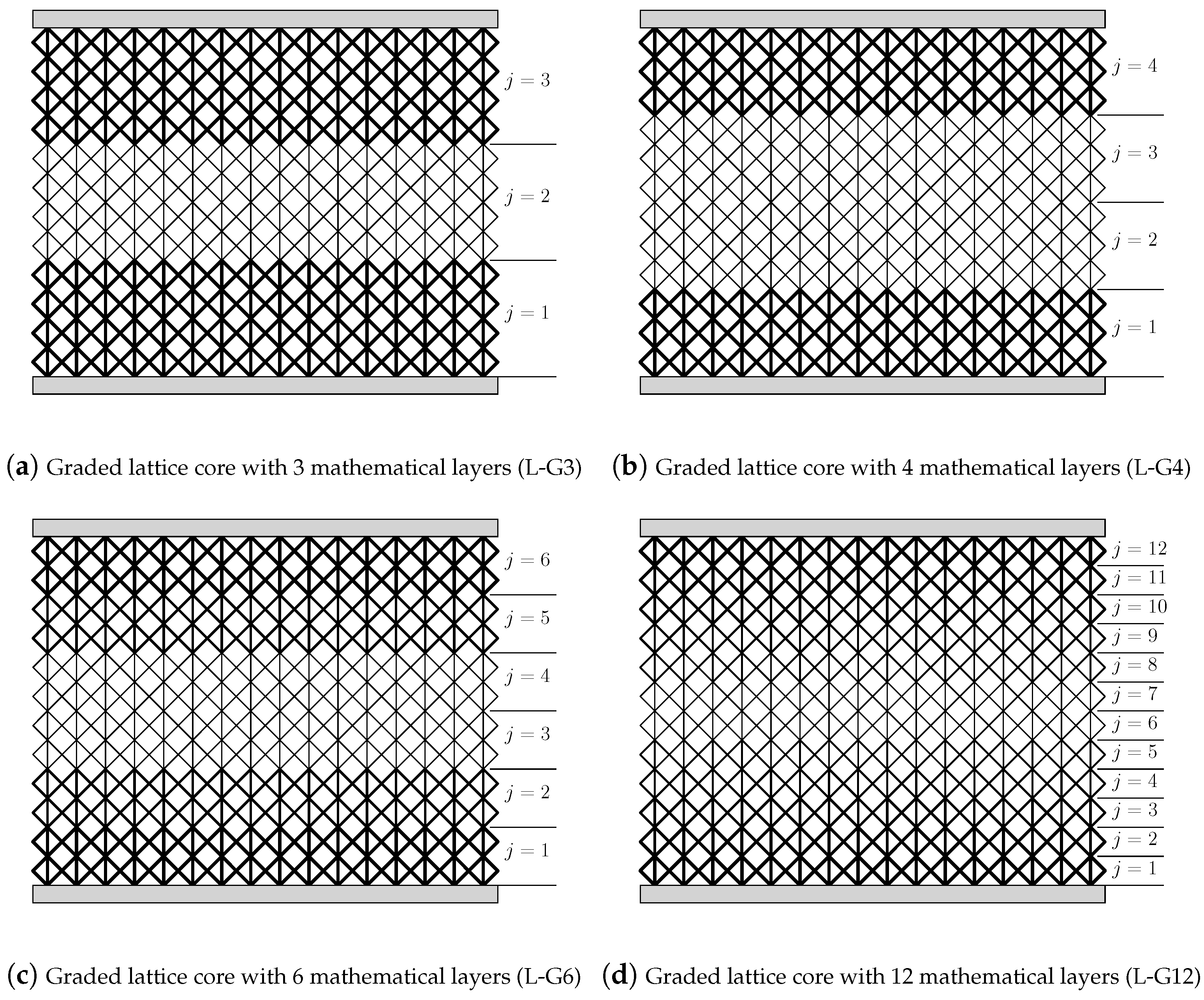
- The core is divided into k mathematical layers. The strut diameter of each mathematical layer represents a design variable.
- The struts’ stresses are determined first in the homogeneous lattice core (iteration ). The maximum stress found in the homogeneous core is set to the allowable stress limit .
- The strut diameter of the j-th mathematical layer for the next iteration is calculated in the following mannerwhere denotes the maximum struts’ stress within the j-th mathematical layer.
- Geometric restrictions are applied to provide a symmetric strut diameter variation through the core thickness.
- The analysis will be stopped when the following condition is statisfied.
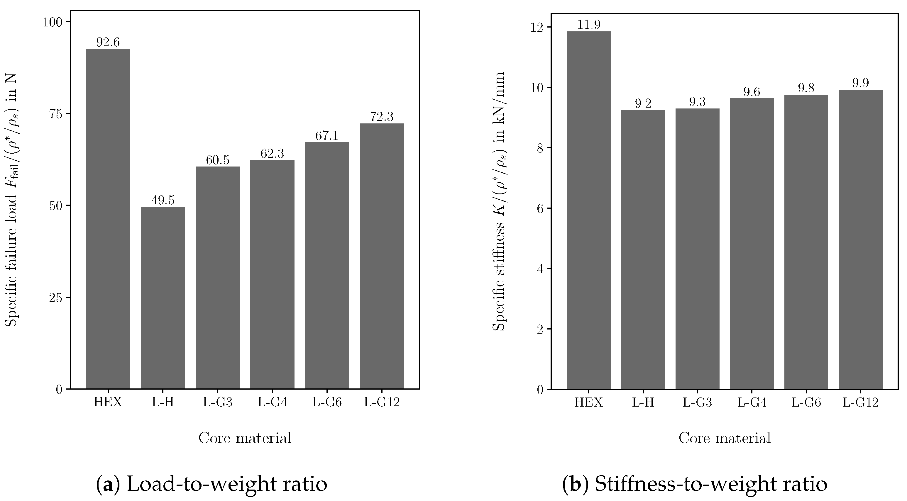
2.4. Failure Load
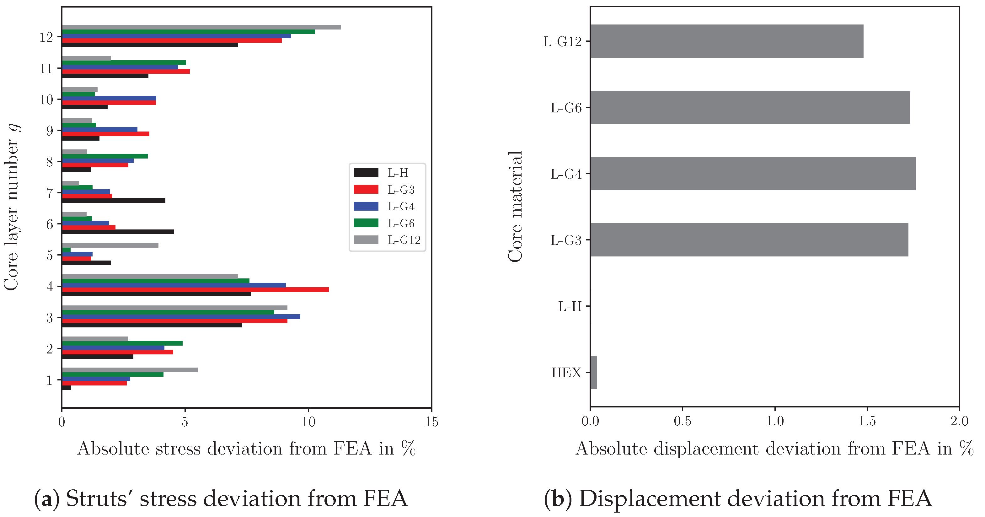
3. Results and Discussion
4. Summary and Conclusions
Author Contributions
Funding
Institutional Review Board Statement
Data Availability Statement
Conflicts of Interest
References
- Fatt, M.S.H.; Sirivolu, D. Marine composite sandwich plates under air and water blasts. Mar. Struct. 2017, 56, 163–185. [Google Scholar] [CrossRef]
- Zinno, A.; Fusco, E.; Prota, A.; Manfredi, G. Multiscale approach for the design of composite sandwich structures for train application. Compos. Struct. 2010, 92, 2208–2219. [Google Scholar] [CrossRef]
- Chai, G.B.; Zhu, S. A review of low-velocity impact on sandwich structures. Proc. Inst. Mech. Eng. Part L J. Mater. Des. Appl. 2011, 225, 207–230. [Google Scholar] [CrossRef]
- He, M.; Hu, W. A study on composite honeycomb sandwich panel structure. Mater. Des. 2008, 29, 709–713. [Google Scholar] [CrossRef]
- Ma, Q.; Rejab, M.; Siregar, J.; Guan, Z. A review of the recent trends on core structures and impact response of sandwich panels. J. Compos. Mater. 2021, 55, 2513–2555. [Google Scholar] [CrossRef]
- Manalo, A.; Aravinthan, T.; Fam, A.; Benmokrane, B. State-of-the-art review on FRP sandwich systems for lightweight civil infrastructure. J. Compos. Constr. 2017, 21, 04016068. [Google Scholar] [CrossRef]
- Jin, X.; Wang, Z.; Ning, J.; Xiao, G.; Liu, E.; Shu, X. Dynamic response of sandwich structures with graded auxetic honeycomb cores under blast loading. Compos. Part B Eng. 2016, 106, 206–217. [Google Scholar] [CrossRef]
- Yu, B.; Han, B.; Su, P.B.; Ni, C.Y.; Zhang, Q.C.; Lu, T.J. Graded square honeycomb as sandwich core for enhanced mechanical performance. Mater. Des. 2016, 89, 642–652. [Google Scholar] [CrossRef]
- Conde, Y.; Pollien, A.; Mortensen, A. Functional grading of metal foam cores for yield-limited lightweight sandwich beams. Scr. Mater. 2006, 54, 539–543. [Google Scholar] [CrossRef]
- Hohe, J.; Hardenacke, V.; Fascio, V.; Girard, Y.; Baumeister, J.; Stöbener, K.; Weise, J.; Lehmhus, D.; Pattofatto, S.; Zeng, H.; et al. Numerical and experimental design of graded cellular sandwich cores for multi-functional aerospace applications. Mater. Des. 2012, 39, 20–32. [Google Scholar] [CrossRef]
- He, S.Y.; Zhang, Y.; Dai, G.; Jiang, J.Q. Preparation of density-graded aluminum foam. Mater. Sci. Eng. A 2014, 618, 496–499. [Google Scholar] [CrossRef]
- Pflug, J.; Vangrimde, B.; Verpoest, I. Material efficiency and cost effectiveness of sandwich materials. In Proceedings of the International SAMPE Symposium and Exhibition, Dayton, OH, USA, 28 September–2 October 2003; SAMPE: Covina, CA, USA, 1999; pp. 1925–1937. [Google Scholar]
- Castanie, B.; Bouvet, C.; Ginot, M. Review of composite sandwich structure in aeronautic applications. Compos. Part C Open Access 2020, 1, 100004. [Google Scholar] [CrossRef]
- Chatterjee, A.; Mishra, A.; Sharma, S.; Bhagchandani, R.K. Review on lightweight materials, additive manufacturing techniques and design optimization of an airplane. In Proceedings of the AIP Conference Proceedings, Vellore, India, 10–12 September 2021; AIP Publishing: New York, NY, USA, 2022; Volume 2653. [Google Scholar]
- Sugiyama, K.; Matsuzaki, R.; Ueda, M.; Todoroki, A.; Hirano, Y. 3D printing of composite sandwich structures using continuous carbon fiber and fiber tension. Compos. Part A Appl. Sci. Manuf. 2018, 113, 114–121. [Google Scholar] [CrossRef]
- Alomar, Z.; Concli, F. A review of the selective laser melting lattice structures and their numerical models. Adv. Eng. Mater. 2020, 22, 2000611. [Google Scholar] [CrossRef]
- Sun, Y.; Guo, L.C.; Wang, T.S.; Yao, L.J.; Sun, X.Y. Bending strength and failure of single-layer and double-layer sandwich structure with graded truss core. Compos. Struct. 2019, 226, 111204. [Google Scholar] [CrossRef]
- Austermann, J.; Redmann, A.J.; Dahmen, V.; Quintanilla, A.L.; Mecham, S.J.; Osswald, T.A. Fiber-reinforced composite sandwich structures by co-curing with additive manufactured epoxy lattices. J. Compos. Sci. 2019, 3, 53. [Google Scholar] [CrossRef]
- Mesto, T.; Sleiman, M.; Khalil, K.; Alfayad, S.; Jacquemin, F. Analyzing sandwich panel with new proposed core for bending and compression resistance. Proc. Inst. Mech. Eng. Part L J. Mater. Des. Appl. 2023, 237, 367–378. [Google Scholar] [CrossRef]
- Zaharia, S.M.; Enescu, L.A.; Pop, M.A. Mechanical performances of lightweight sandwich structures produced by material extrusion-based additive manufacturing. Polymers 2020, 12, 1740. [Google Scholar] [CrossRef]
- Khoshgoftar, M.; Barkhordari, A.; Limuti, M.; Buccino, F.; Vergani, L.; Mirzaali, M. Bending analysis of sandwich panel composite with a re-entrant lattice core using zig-zag theory. Sci. Rep. 2022, 12, 15796. [Google Scholar] [CrossRef] [PubMed]
- Wang, Y.; Liu, F.; Zhang, X.; Zhang, K.; Wang, X.; Gan, D.; Yang, B. Cell-size graded sandwich enhances additive manufacturing fidelity and energy absorption. Int. J. Mech. Sci. 2021, 211, 106798. [Google Scholar] [CrossRef]
- Li, H.; Hu, Y.; Chen, J.; Shou, D.; Li, B. Lightweight meta-lattice sandwich panels for remarkable vibration mitigation: Analytical prediction, numerical analysis and experimental validations. Compos. Part A Appl. Sci. Manuf. 2022, 163, 107218. [Google Scholar] [CrossRef]
- Li, C.; Shen, H.S.; Wang, H.; Yu, Z. Large amplitude vibration of sandwich plates with functionally graded auxetic 3D lattice core. Int. J. Mech. Sci. 2020, 174, 105472. [Google Scholar] [CrossRef]
- Bici, M.; Brischetto, S.; Campana, F.; Ferro, C.G.; Seclì, C.; Varetti, S.; Maggiore, P.; Mazza, A. Development of a multifunctional panel for aerospace use through SLM additive manufacturing. Procedia CIRP 2018, 67, 215–220. [Google Scholar] [CrossRef]
- Tian, J.; Lu, T.; Hodson, H.; Queheillalt, D.; Wadley, H. Cross flow heat exchange of textile cellular metal core sandwich panels. Int. J. Heat Mass Transf. 2007, 50, 2521–2536. [Google Scholar] [CrossRef]
- Kotzem, D.; Tazerout, D.; Arold, T.; Niendorf, T.; Walther, F. Failure mode map for E-PBF manufactured Ti6Al4V sandwich panels. Eng. Fail. Anal. 2021, 121, 105159. [Google Scholar] [CrossRef]
- Ghannadpour, S.; Mahmoudi, M.; Nedjad, K.H. Structural behavior of 3D-printed sandwich beams with strut-based lattice core: Experimental and numerical study. Compos. Struct. 2022, 281, 115113. [Google Scholar] [CrossRef]
- Zhang, X.; Zhou, H.; Shi, W.; Zeng, F.; Zeng, H.; Chen, G. Vibration tests of 3D printed satellite structure made of lattice sandwich panels. AIAA J. 2018, 56, 4213–4217. [Google Scholar] [CrossRef]
- Boschetto, A.; Bottini, L.; Macera, L.; Vatanparast, S. Additive Manufacturing for Lightweighting Satellite Platform. Appl. Sci. 2023, 13, 2809. [Google Scholar] [CrossRef]
- Namasivayam, U.M.; Seepersad, C.C. Topology design and freeform fabrication of deployable structures with lattice skins. Rapid Prototyp. J. 2011, 17, 5–16. [Google Scholar] [CrossRef]
- Karttunen, A.T.; Reddy, J.; Romanoff, J. Two-scale micropolar plate model for web-core sandwich panels. Int. J. Solids Struct. 2019, 170, 82–94. [Google Scholar] [CrossRef]
- Song, J.; Tang, Q.; Feng, Q.; Ma, S.; Guo, F.; Han, Q. Investigation on the modelling approach for variable-density lattice structures fabricated using selective laser melting. Mater. Des. 2021, 212, 110236. [Google Scholar] [CrossRef]
- Bai, L.; Gong, C.; Chen, X.; Sun, Y.; Xin, L.; Pu, H.; Peng, Y.; Luo, J. Mechanical properties and energy absorption capabilities of functionally graded lattice structures: Experiments and simulations. Int. J. Mech. Sci. 2020, 182, 105735. [Google Scholar] [CrossRef]
- Khan, M.; Syed, A.; Ijaz, H.; Shah, R. Experimental and numerical analysis of flexural and impact behaviour of glass/pp sandwich panel for automotive structural applications. Adv. Compos. Mater. 2018, 27, 367–386. [Google Scholar] [CrossRef]
- Suzuki, T.; Aoki, T.; Ogasawara, T.; Fujita, K. Nonablative lightweight thermal protection system for Mars Aeroflyby Sample collection mission. Acta Astronaut. 2017, 136, 407–420. [Google Scholar] [CrossRef]
- Souza, J.; Großmann, A.; Mittelstedt, C. Micromechanical analysis of the effective properties of lattice structures in additive manufacturing. Addit. Manuf. 2018, 23, 53–69. [Google Scholar] [CrossRef]
- Sereshk, M.R.V.; Triplett, K.; St John, C.; Martin, K.; Gorin, S.; Avery, A.; Byer, E.; St Pierre, C.; Soltani-Tehrani, A.; Shamsaei, N. A Computational and Experimental Investigation into Mechanical Characterizations of Strut-Based Lattice Structures. In Proceedings of the 2019 International Solid Freeform Fabrication Symposium, Austin, TX, USA, 12–14 August 2019; University of Texas at Austin: Austin, TX, USA, 2019. [Google Scholar]
- Gibson, L.J.; Ashby, M.F. The mechanics of honeycombs. In Cellular Solids: Structure and Properties, 2nd ed.; Cambridge Solid State Science Series; Cambridge University Press: Cambridge, UK, 1997; pp. 93–174. [Google Scholar]
- Georges, H.; Mittelstedt, C.; Becker, W. Energy-based strut stress analysis of 3D lattice cores in sandwich panels. Eur. J. Mech. A/Solids 2023, 100, 105007. [Google Scholar] [CrossRef]
- Reddy, J.N. Mechanics of Laminated Composite Plates and Shells: Theory and Analysis; CRC Press: Boca Raton, FL, USA, 2003. [Google Scholar]
- Topping, B. Shape optimization of skeletal structures: A review. J. Struct. Eng. 1983, 109, 1933–1951. [Google Scholar] [CrossRef]
- Patnaik, S.N.; Hopkins, D.A. Optimality of a fully stressed design. Comput. Methods Appl. Mech. Eng. 1998, 165, 215–221. [Google Scholar] [CrossRef]
- Zhang, L.; Chen, Y.; He, R.; Bai, X.; Zhang, K.; Ai, S.; Yang, Y.; Fang, D. Bending behavior of lightweight C/SiC pyramidal lattice core sandwich panels. Int. J. Mech. Sci. 2020, 171, 105409. [Google Scholar] [CrossRef]
- Yuan, W.; Song, H.; Huang, C. Failure maps and optimal design of metallic sandwich panels with truss cores subjected to thermal loading. Int. J. Mech. Sci. 2016, 115, 56–67. [Google Scholar] [CrossRef]
- Hao, N.; Wang, Y.; Song, Y.; Ruan, S.; Ma, Q.; Wang, Z. Load-bearing behaviors of sandwich plates with non-uniformly distributed grid cores: Static compression and bending. J. Mater. Sci. 2023, 58, 16488–16506. [Google Scholar] [CrossRef]
- Omachi, A.; Ushijima, K.; Chen, D.H.; Cantwell, W.J. Prediction of failure modes and peak loads in lattice sandwich panels under three-point loading. J. Sandw. Struct. Mater. 2020, 22, 1635–1659. [Google Scholar] [CrossRef]
- Monteiro, J.; Sardinha, M.; Alves, F.; Ribeiro, A.; Reis, L.; Deus, A.; Leite, M.; Vaz, M.F. Evaluation of the effect of core lattice topology on the properties of sandwich panels produced by additive manufacturing. Proc. Inst. Mech. Eng. Part L J. Mater. Des. Appl. 2021, 235, 1312–1324. [Google Scholar] [CrossRef]
- Pollien, A.; Conde, Y.; Pambaguian, L.; Mortensen, A. Graded open-cell aluminium foam core sandwich beams. Mater. Sci. Eng. A 2005, 404, 9–18. [Google Scholar] [CrossRef]
- Georges, H.; Großmann, A.; Mittelstedt, C.; Becker, W. Structural modeling of sandwich panels with additively manufactured strut-based lattice cores. Addit. Manuf. 2022, 55, 102788. [Google Scholar] [CrossRef]
- Cui, X.; Zhao, L.; Wang, Z.; Zhao, H.; Fang, D. Dynamic response of metallic lattice sandwich structures to impulsive loading. Int. J. Impact Eng. 2012, 43, 1–5. [Google Scholar] [CrossRef]
- Wang, X.; Wei, K.; Wang, K.; Yang, X.; Qu, Z.; Fang, D. Effective thermal conductivity and heat transfer characteristics for a series of lightweight lattice core sandwich panels. Appl. Therm. Eng. 2020, 173, 115205. [Google Scholar] [CrossRef]
- Yan, H.; Yang, X.; Lu, T.; Xie, G. Convective heat transfer in a lightweight multifunctional sandwich panel with X-type metallic lattice core. Appl. Therm. Eng. 2017, 127, 1293–1304. [Google Scholar] [CrossRef]
- Wicks, N.; Hutchinson, J.W. Performance of sandwich plates with truss cores. Mech. Mater. 2004, 36, 739–751. [Google Scholar] [CrossRef]
- Tarlochan, F. Sandwich structures for energy absorption applications: A review. Materials 2021, 14, 4731. [Google Scholar] [CrossRef] [PubMed]


Disclaimer/Publisher’s Note: The statements, opinions and data contained in all publications are solely those of the individual author(s) and contributor(s) and not of MDPI and/or the editor(s). MDPI and/or the editor(s) disclaim responsibility for any injury to people or property resulting from any ideas, methods, instructions or products referred to in the content. |
© 2024 by the authors. Licensee MDPI, Basel, Switzerland. This article is an open access article distributed under the terms and conditions of the Creative Commons Attribution (CC BY) license (https://creativecommons.org/licenses/by/4.0/).
Share and Cite
Georges, H.; García Solera, D.; Aguilar Borasteros, C.; Metar, M.; Song, G.; Mandava, R.; Becker, W.; Mittelstedt, C. Mechanical Performance Comparison of Sandwich Panels with Graded Lattice and Honeycomb Cores. Biomimetics 2024, 9, 96. https://doi.org/10.3390/biomimetics9020096
Georges H, García Solera D, Aguilar Borasteros C, Metar M, Song G, Mandava R, Becker W, Mittelstedt C. Mechanical Performance Comparison of Sandwich Panels with Graded Lattice and Honeycomb Cores. Biomimetics. 2024; 9(2):96. https://doi.org/10.3390/biomimetics9020096
Chicago/Turabian StyleGeorges, Hussam, Diego García Solera, Carlos Aguilar Borasteros, Mohmad Metar, Gyeongseob Song, Rahul Mandava, Wilfried Becker, and Christian Mittelstedt. 2024. "Mechanical Performance Comparison of Sandwich Panels with Graded Lattice and Honeycomb Cores" Biomimetics 9, no. 2: 96. https://doi.org/10.3390/biomimetics9020096
APA StyleGeorges, H., García Solera, D., Aguilar Borasteros, C., Metar, M., Song, G., Mandava, R., Becker, W., & Mittelstedt, C. (2024). Mechanical Performance Comparison of Sandwich Panels with Graded Lattice and Honeycomb Cores. Biomimetics, 9(2), 96. https://doi.org/10.3390/biomimetics9020096