
An Experimental and Simulation Study of the Active Camber Morphing Concept on Airfoils Using Bio-Inspired Structures
 , , , ,
Abstract
1. Introduction
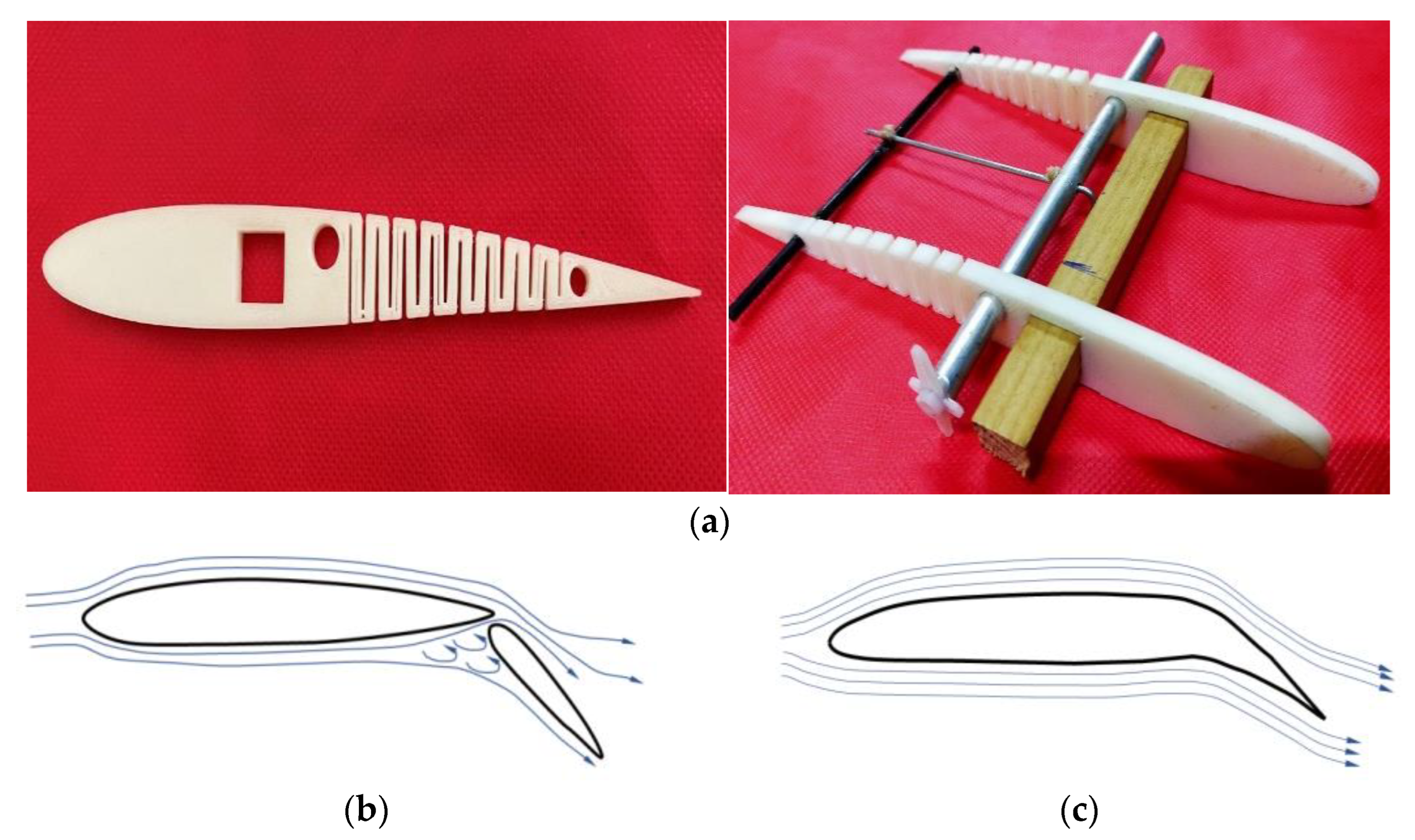
2. Kerf Bending Active Camber Concept
Advantages of Kerf Bending
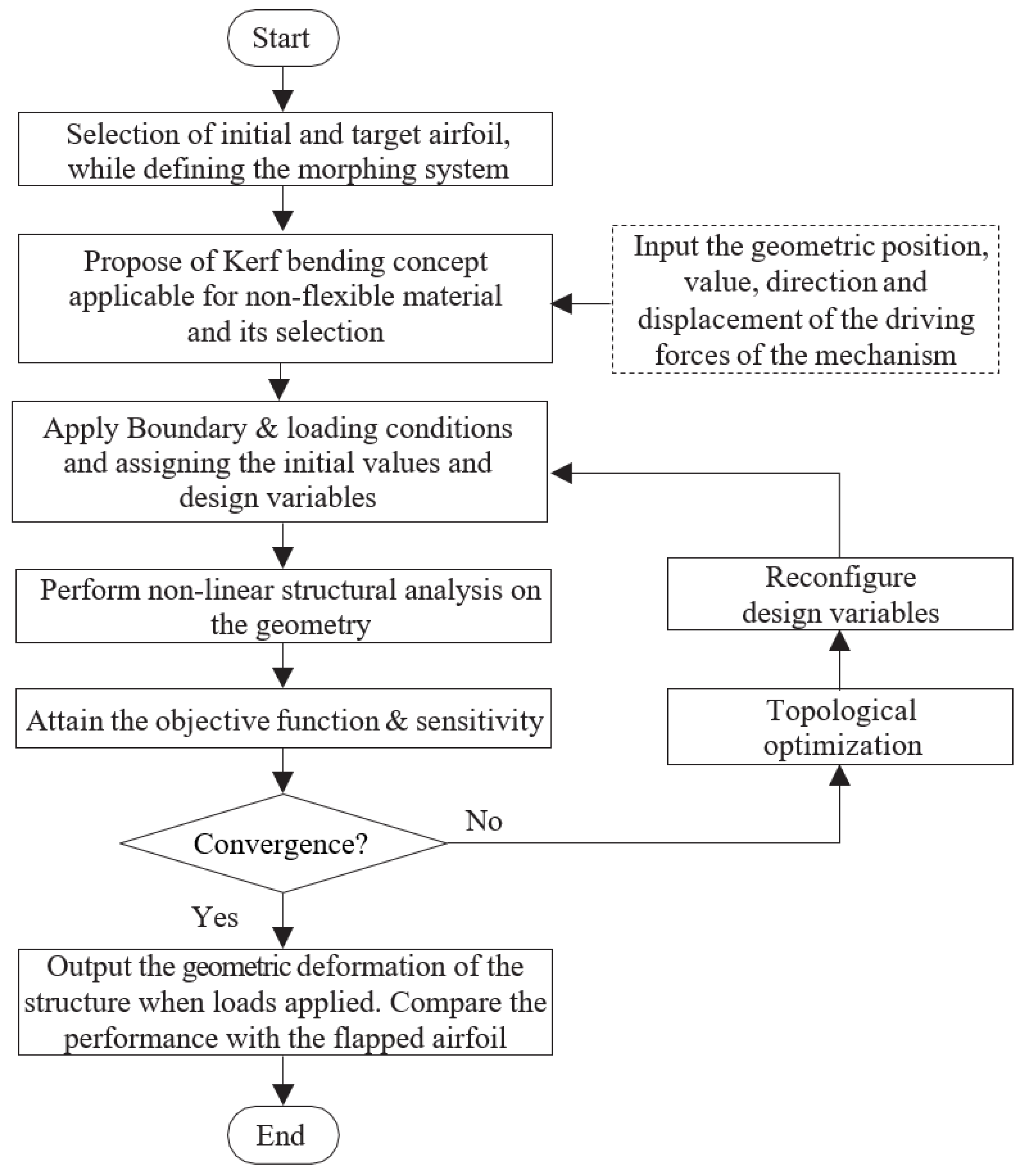
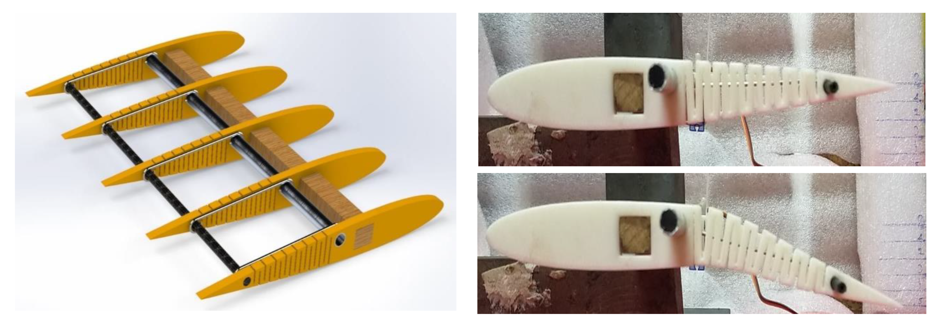
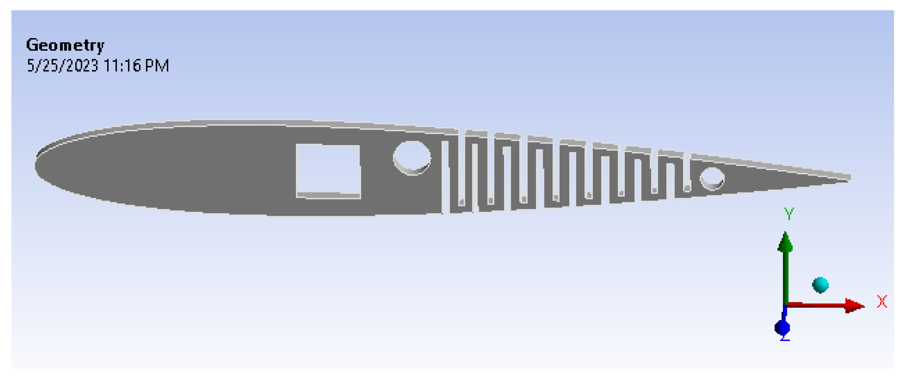
3. Detailed Design of Morphing (Kerf Bending) Structure
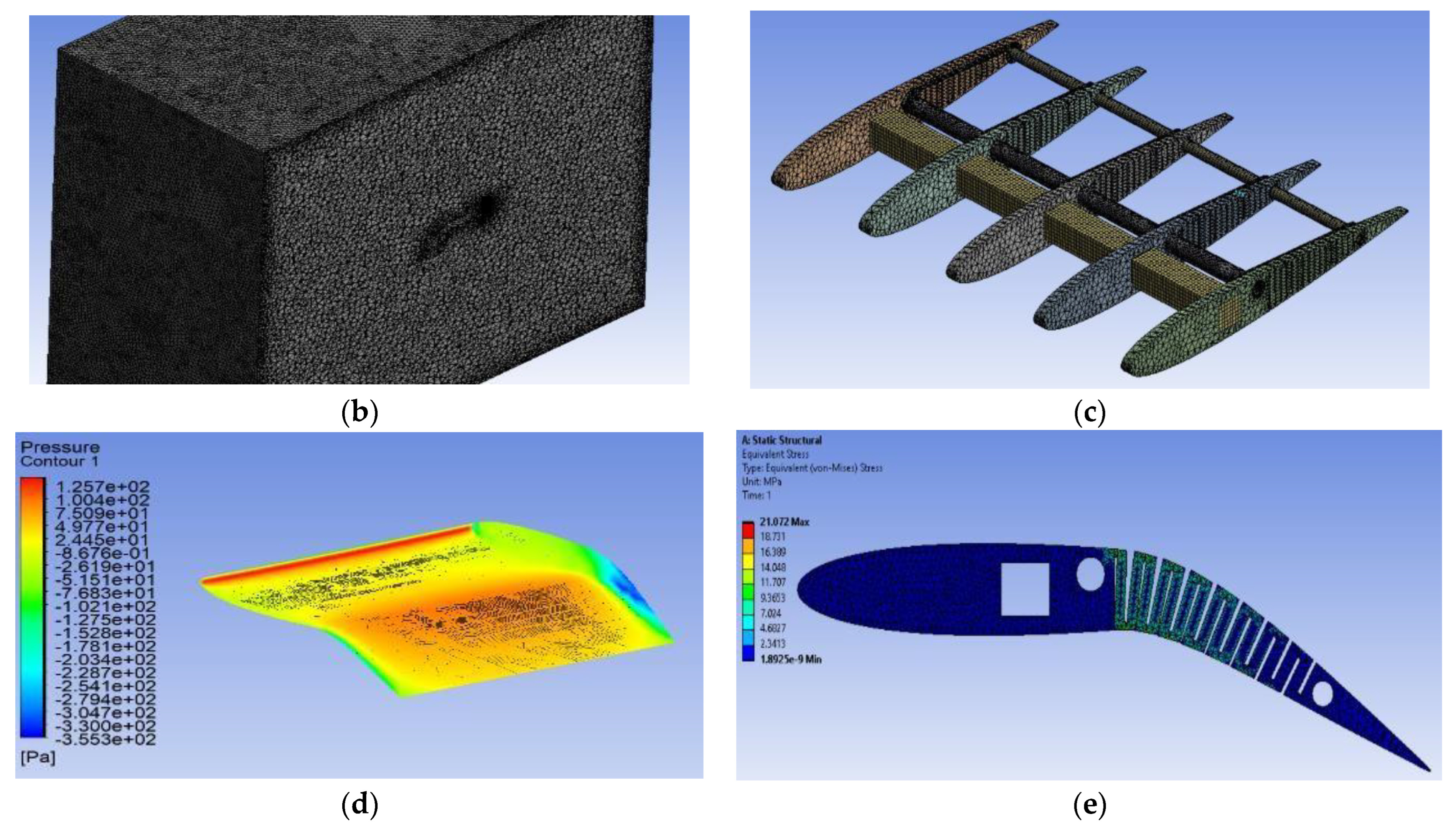
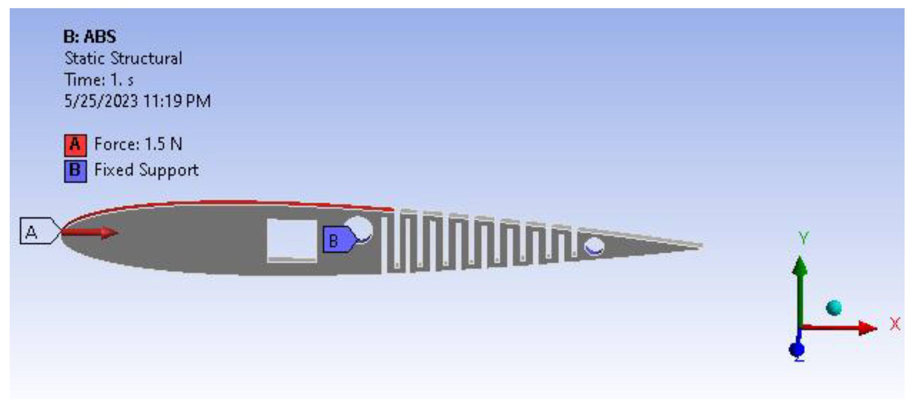
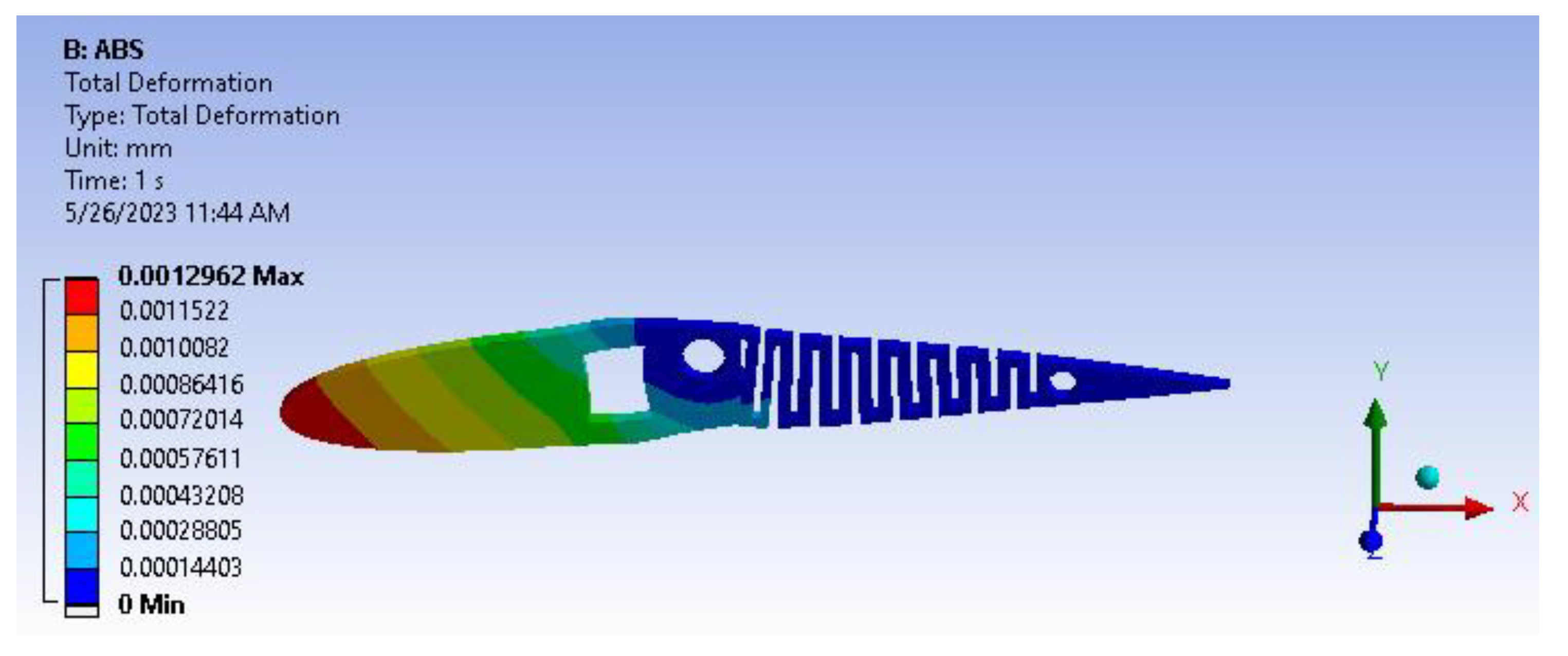
4. Static Structural Analysis
5. Aerodynamic Performance Analysis
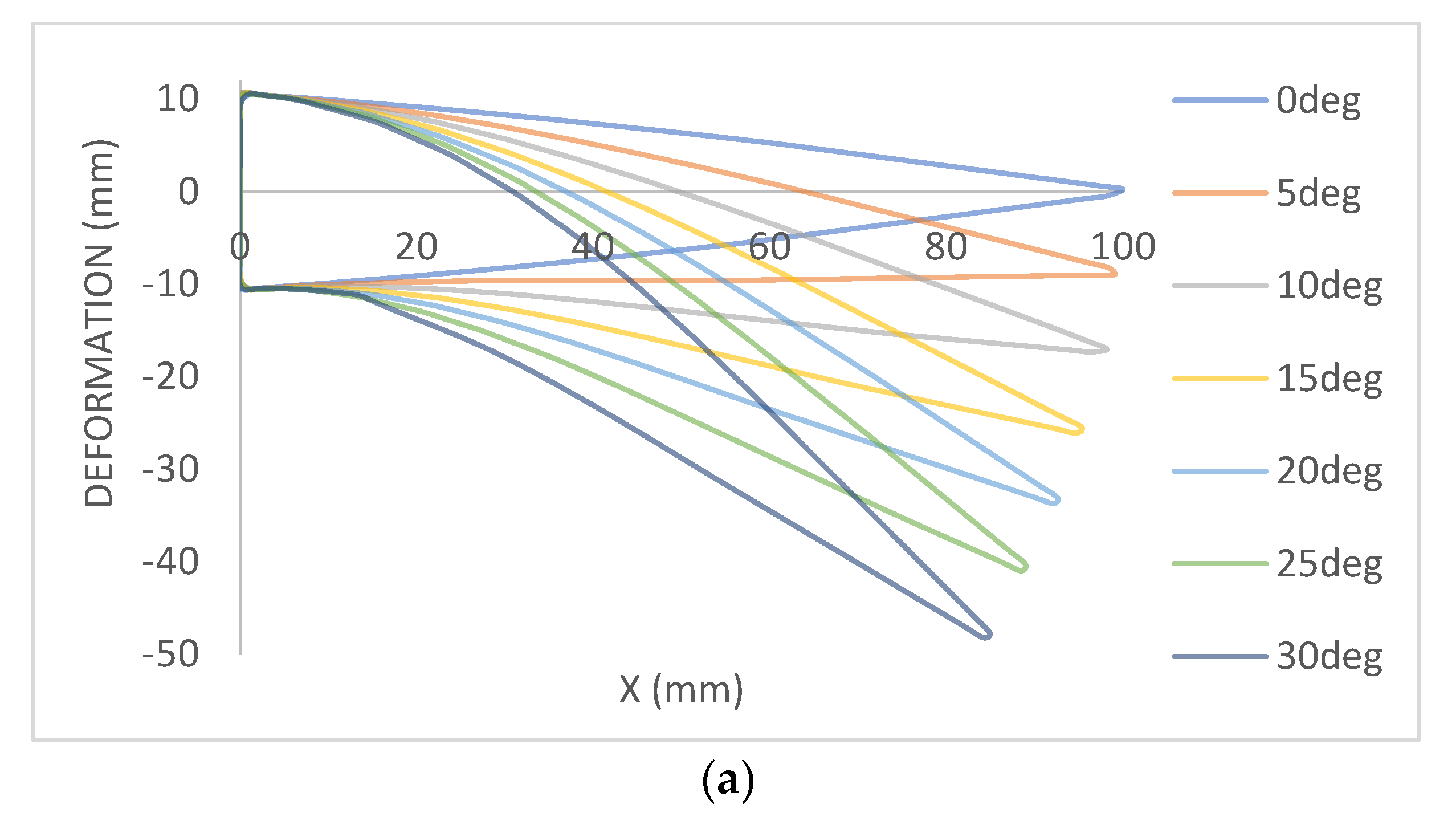
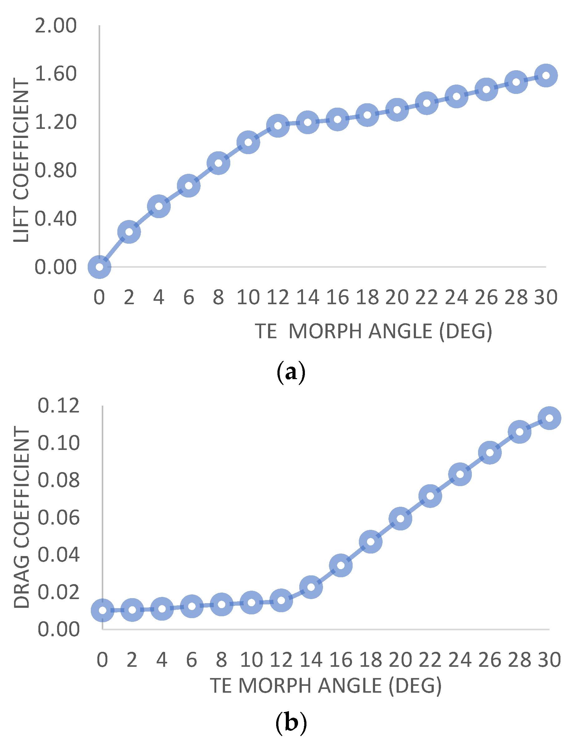
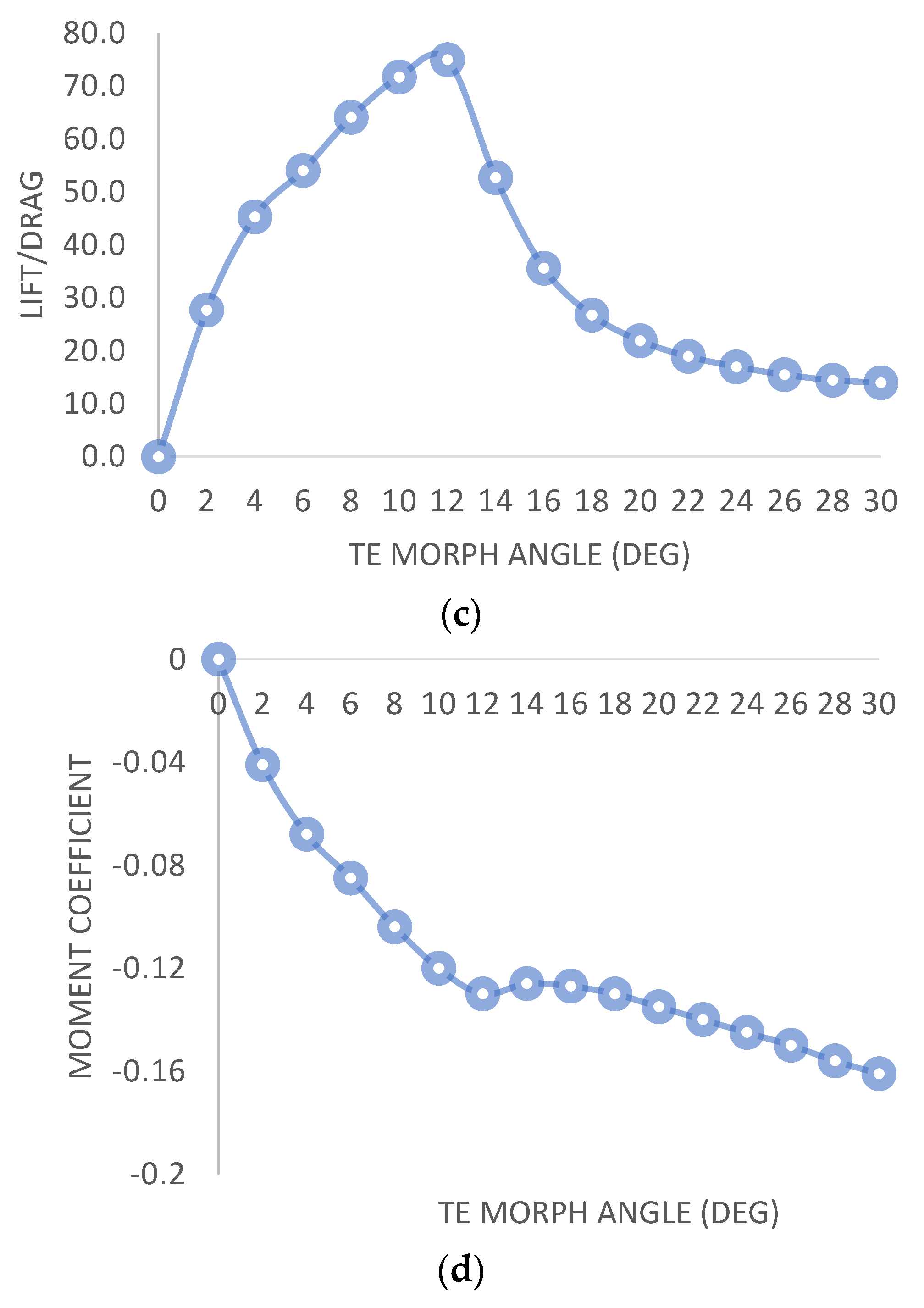
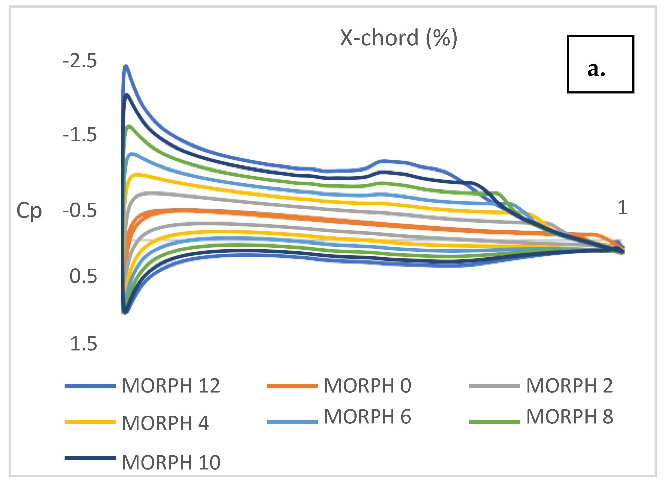
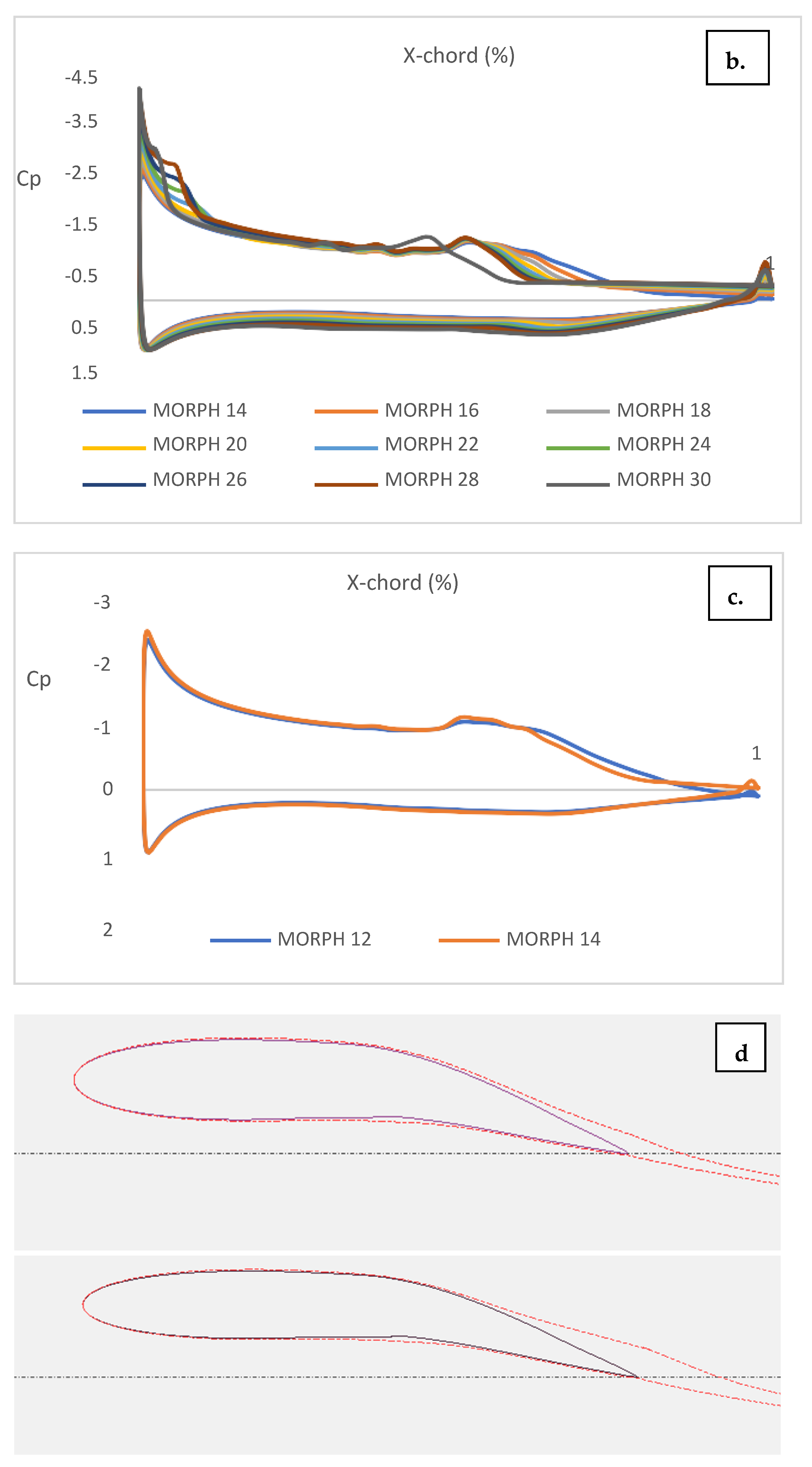
5.1. Characteristics of NACA 0012 for Different Morph Angles
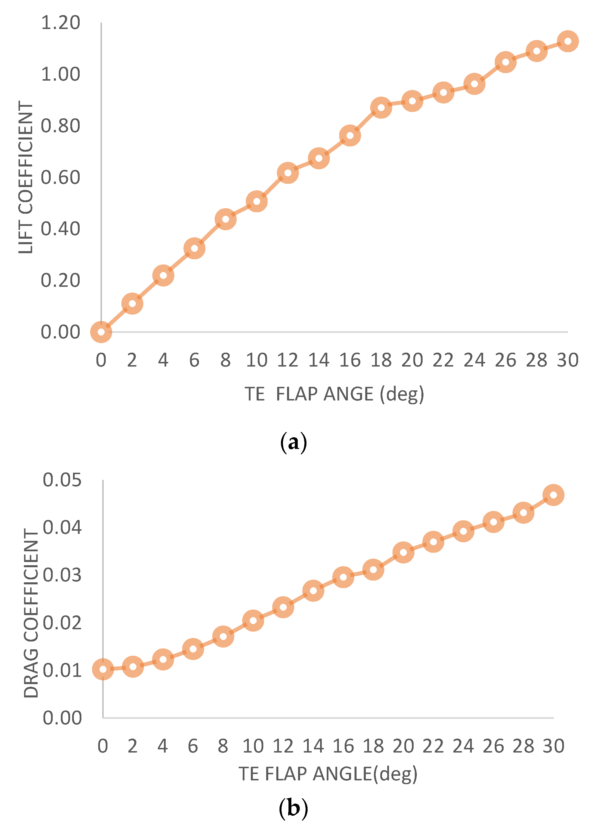
5.2. Characteristics of NACA 0012 for Different Flap Angles
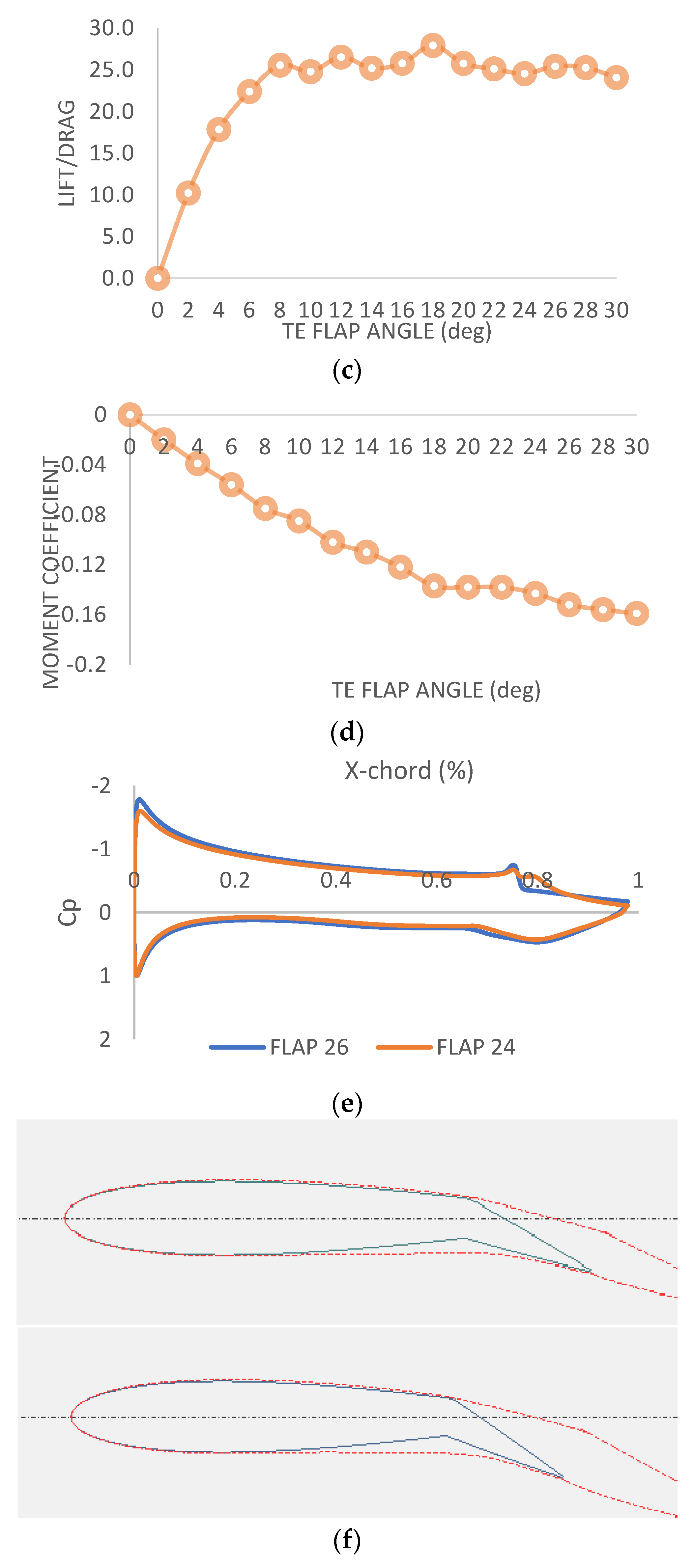
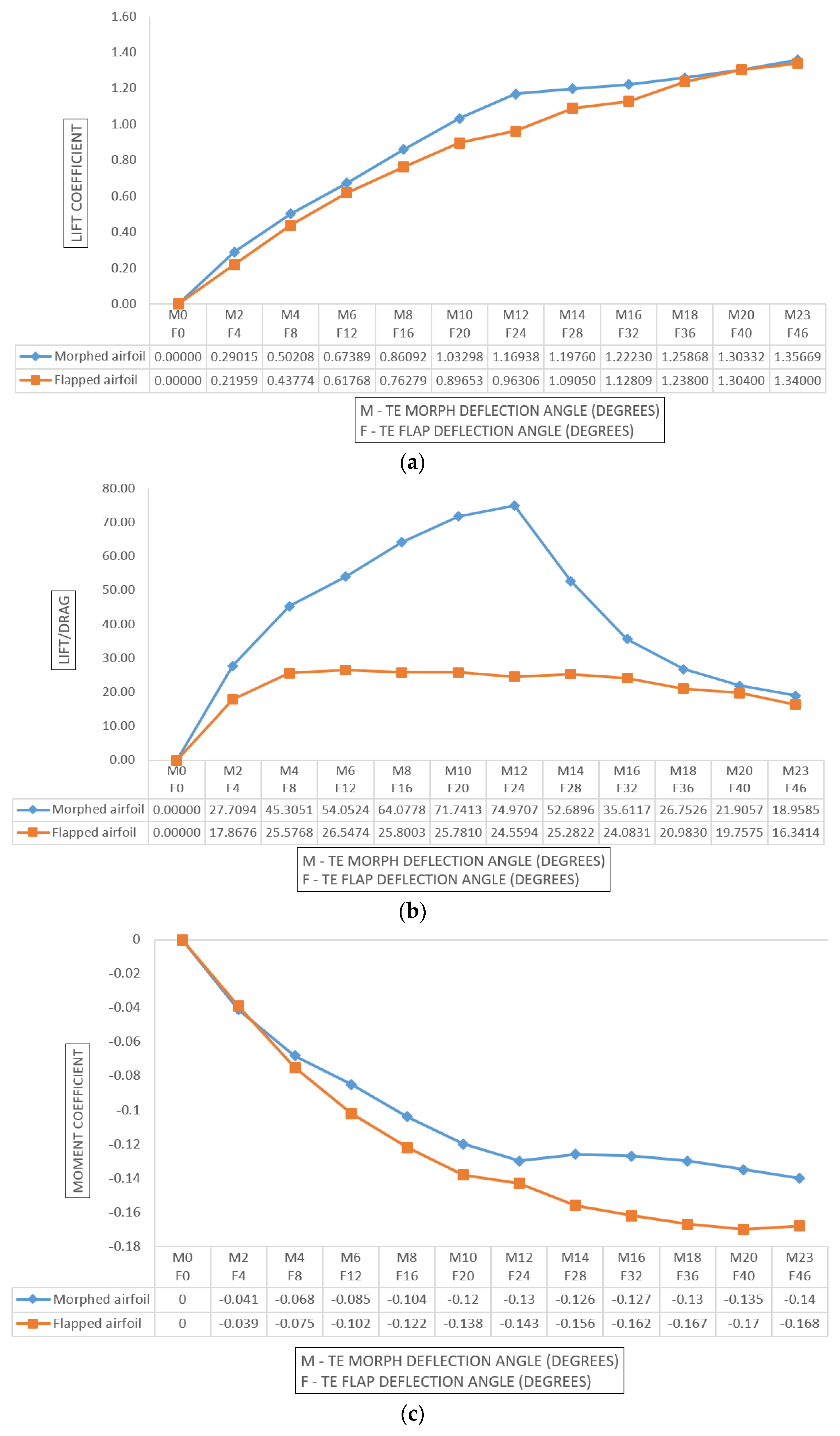
5.3. Performance Analysis: Comparison of Flapped and Morphed Airfoil
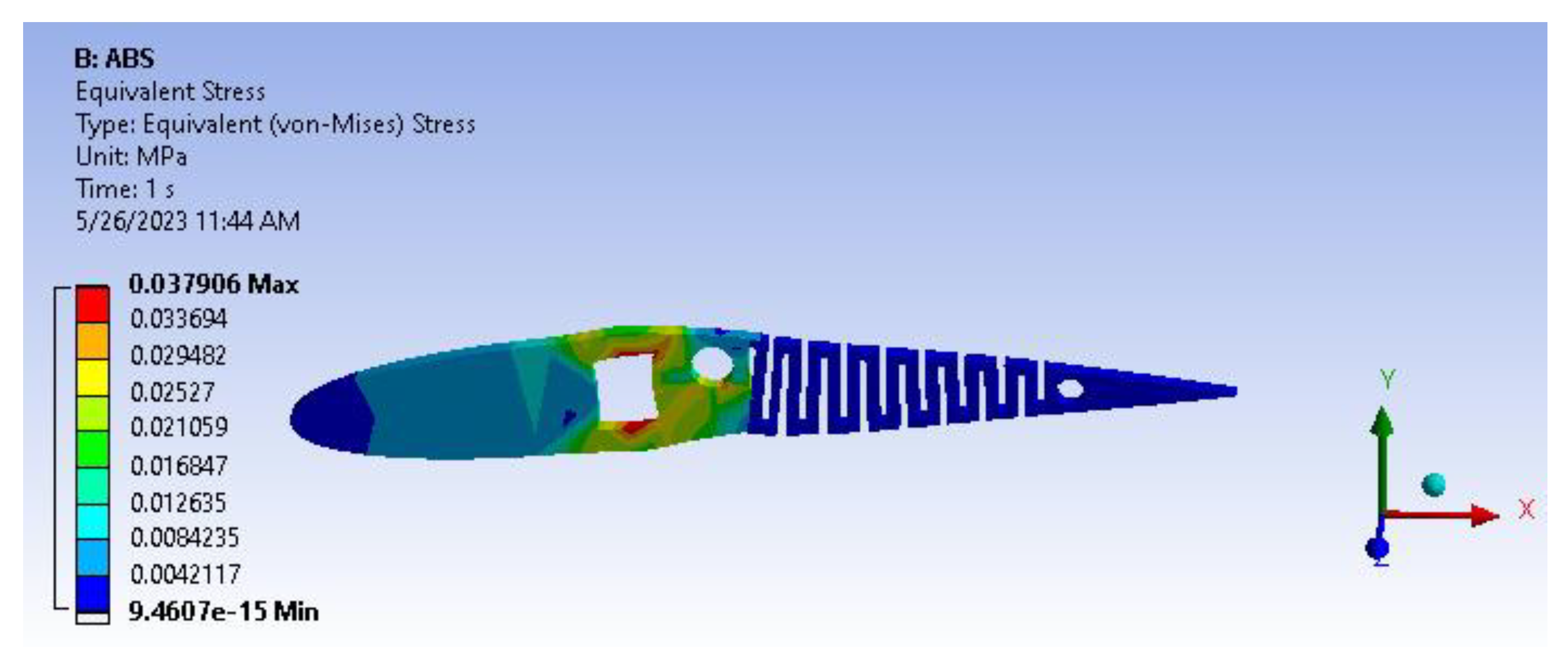
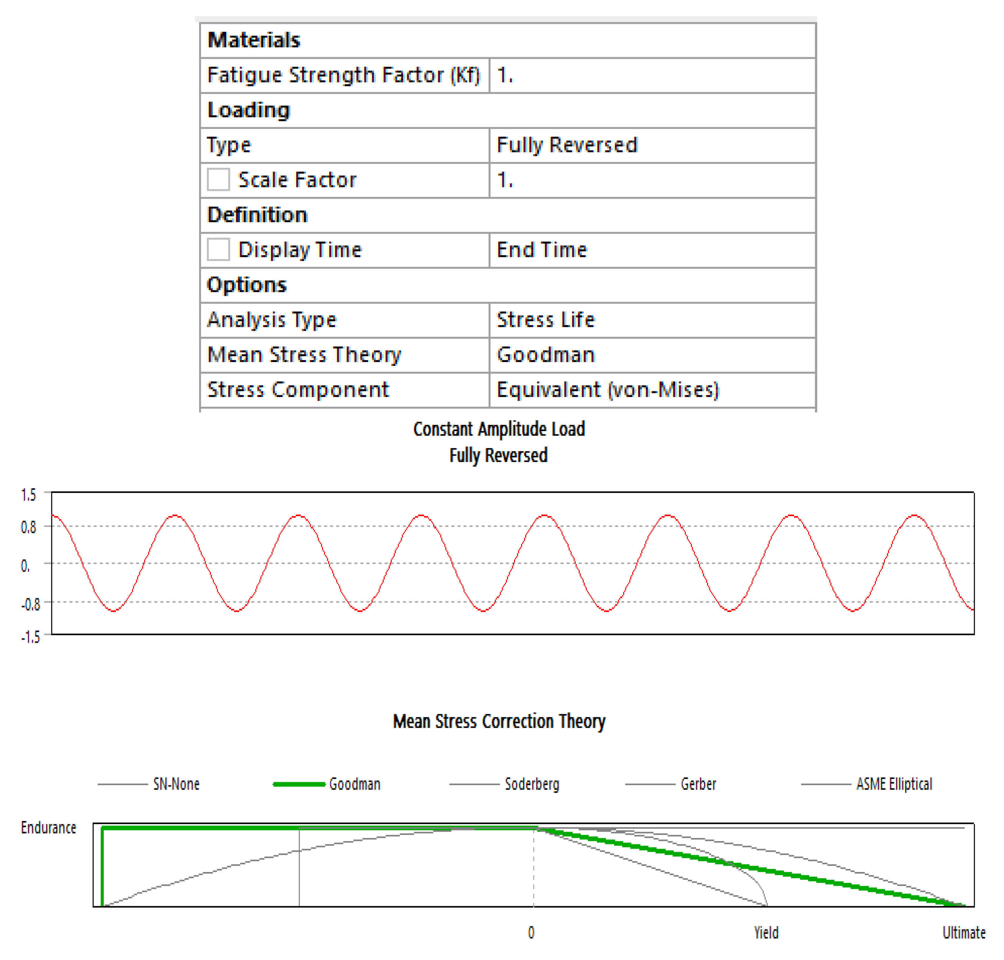
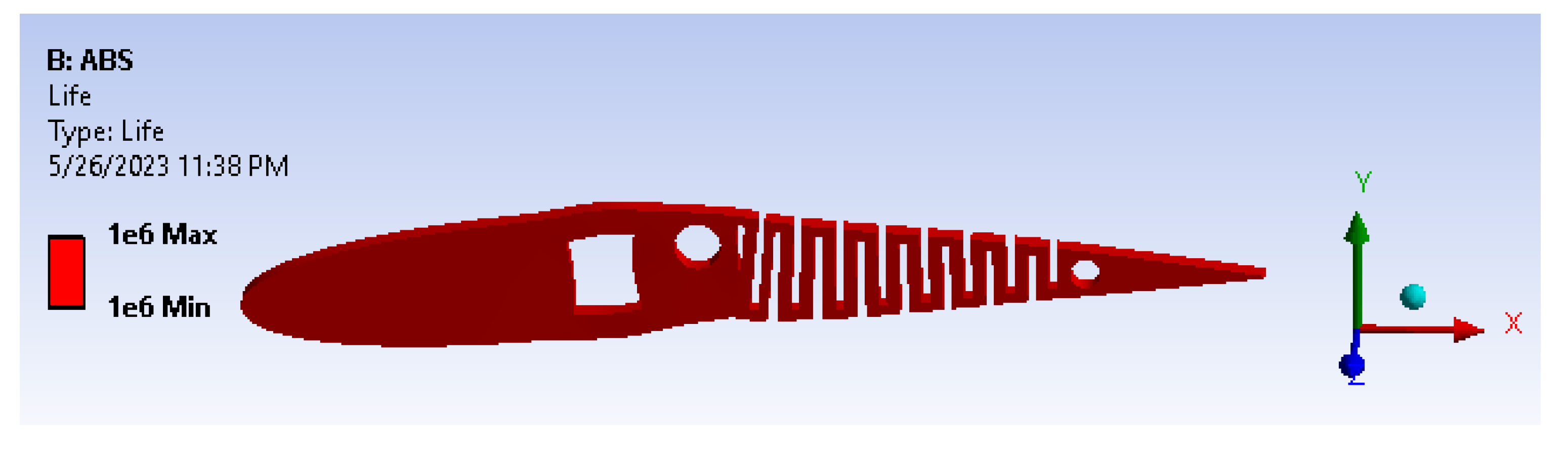
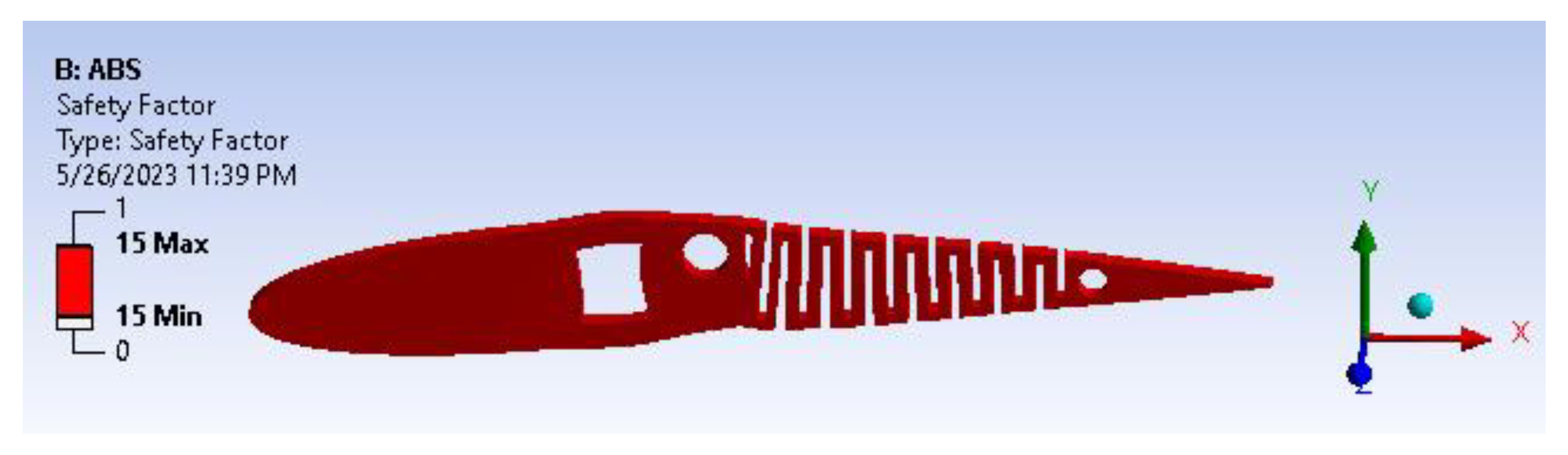
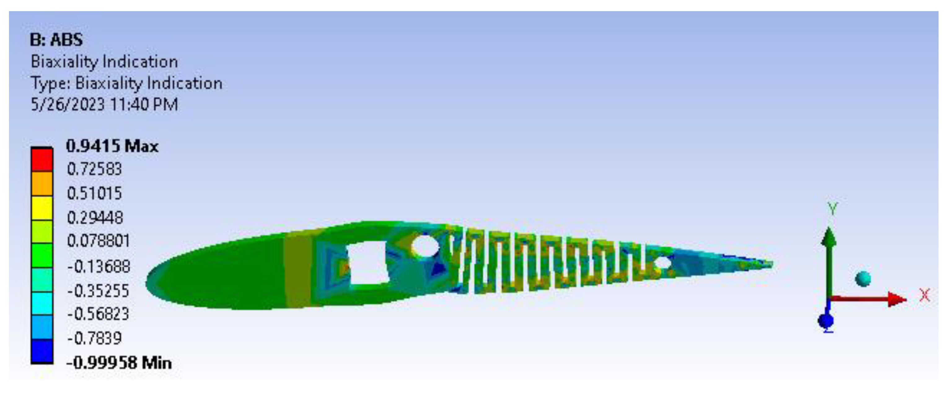
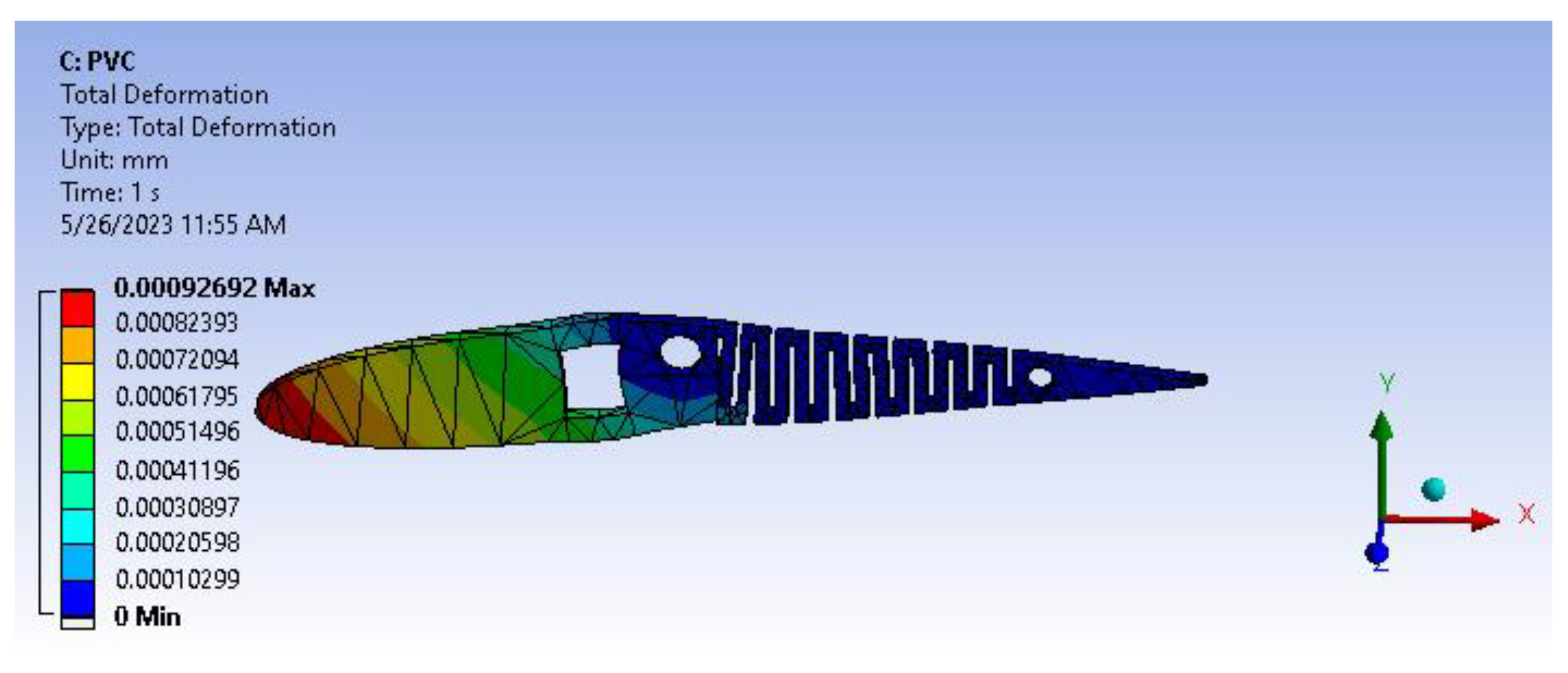
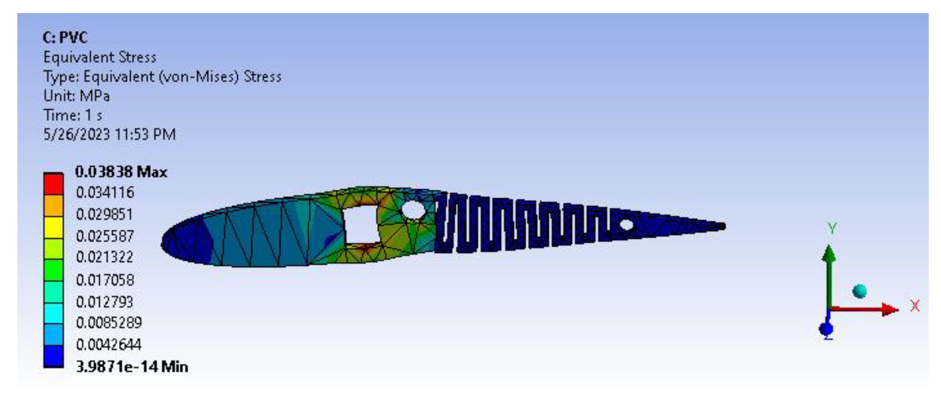
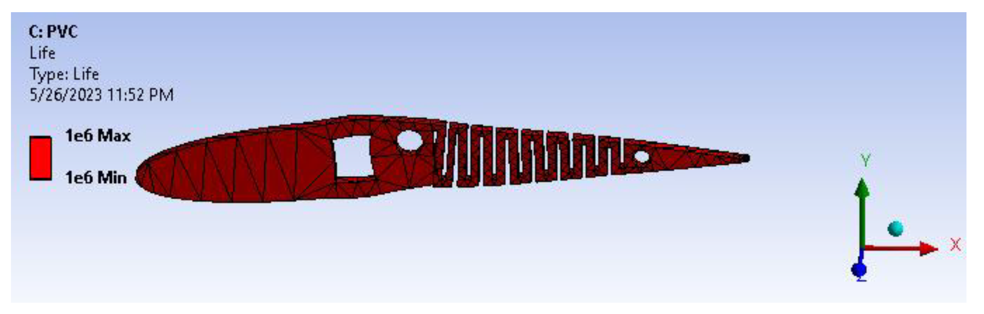
5.4. Fatigue Analysis
5.4.1. ABS
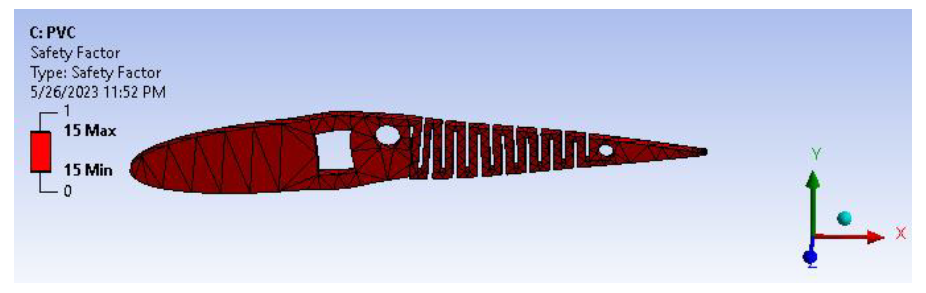
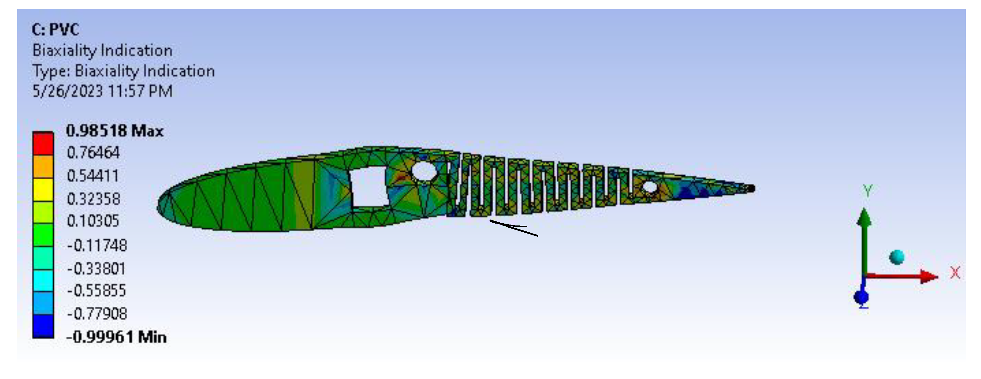
5.4.2. PVC
6. Conclusions
- This design is particularly suitable for short take-off and landing (STOL) aircraft and those operating in stall and low-speed flight conditions, providing better engineering and economic performance and improved functionality compared to conventional wing systems. It is well-known that real-world problems on Earth are nonlinear, and this is also true for the behavior of the skin. However, this study focuses solely on the aerodynamic approach using CFD and does not consider the structural analysis behavior. Although researchers are working on using man-made materials to address this issue, the cost aspects of such solutions remain difficult to estimate at this time.
- In this case, the maximum displacement at 30 degrees of deflection is 47.45 mm, and the maximum stress is 21 MPa. The yield strength of ABS material is 41.14 MPa. This kerf morphing structure with a safety factor of 2.5 can withstand structural and aerodynamic loads.
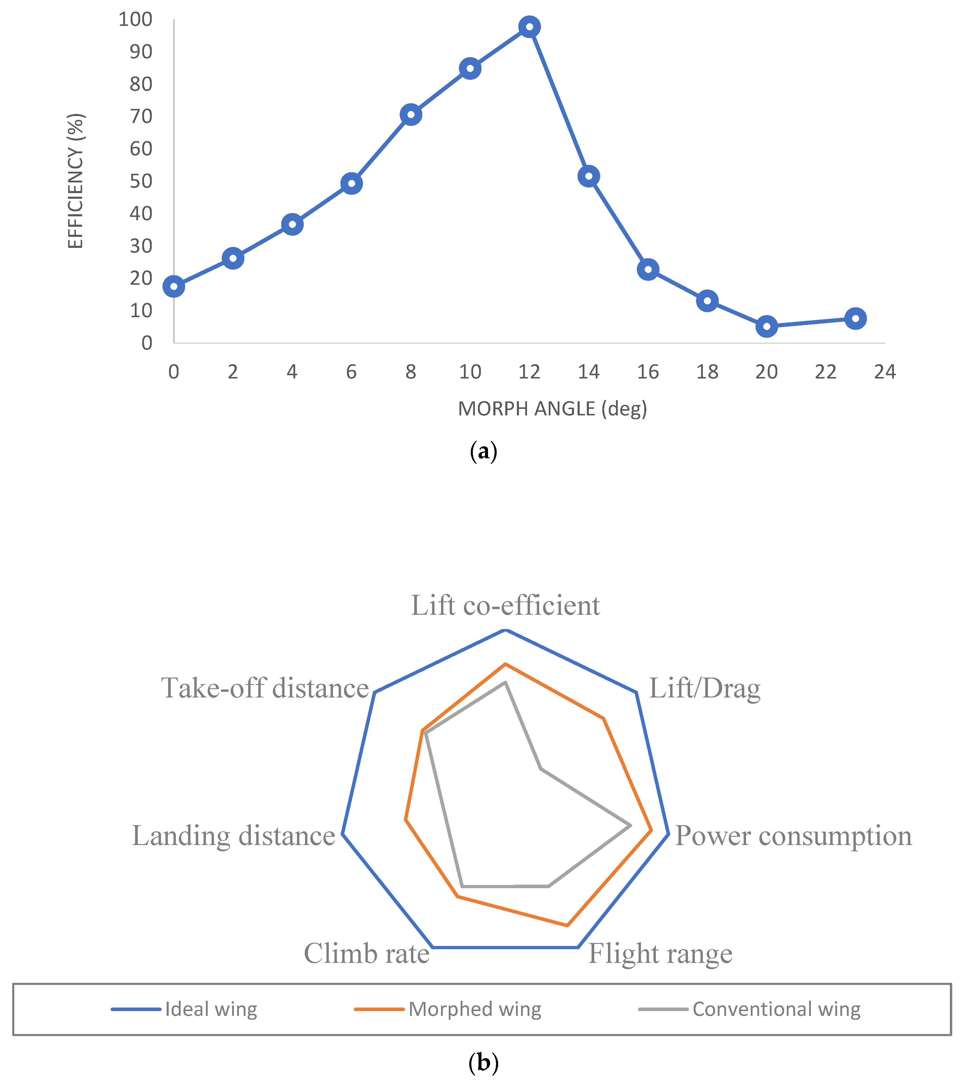
- Analysis results of flap and morph showed 27% efficiency, validated through convergence criteria in ANSYS CFX.
- Furthermore, for future work, it is recommended to conduct comprehensive experimental studies accompanied by a detailed comparative analysis between analytical and experimental results. At the initial stage, it is crucial to prioritize simulations that incorporate all relevant parameters based on real-time conditions. This will enable a more thorough understanding and evaluation of the system under study.
- The fatigue calculations based on the stress-based approach indicate that PVC material has a higher life-carrying capacity compared to ABS. This implies that PVC is more resistant to fatigue failure and can endure a greater number of load cycles before experiencing structural degradation.
Author Contributions
Funding
Institutional Review Board Statement
Informed Consent Statement
Data Availability Statement
Acknowledgments
Conflicts of Interest
Abbreviations
| α | Angle of attack (AOA) |
| Cl | Lift coefficient |
| Cd | Drag coefficient |
| Cl/Cd | Lift–drag coefficient ratio |
| Cm | Pitching movement coefficient |
| TE | Trailing edge |
| Cp | Centre of Pressure |
| Coefficient of change in lift with respect to change in angle of attack | |
| Coefficient of change in drag with respect to change in angle of attack | |
| Coefficient of change in moment with respect to change in angle of attack | |
| L/D | Lift to drag |
| UAV | Unmanned aerial vehicle |
| NASA | National Aeronautics and Space Administration |
| DARPA | Defense Advanced Research Projects Agency |
| FishBAC | Fish bone active camber |
| MAC | Mean aerodynamic chord |
| NACA | National Advisory Committee for Aeronautics |
| ABS | Acrylonitrile butadiene styrene |
| CFD | Computational fluid dynamics |
| XFLR5 | Analysis tool for airfoils, wings and planes operating at low Reynolds numbers |
| Pugh Chart | Method used to analyze different ideas and to determine the optimal choice |
| STOL | Short take-off and landing |
References
- Klaassen van Oorschot, B.; Mistick, E.A.; Tobalske, B.W. Aerodynamic consequences of wing morphing during emulated take-off and gliding in birds. J. Exp. Biol. 2016, 219, 3146–3154. [Google Scholar] [CrossRef] [PubMed]
- Kaygan, E. Aerodynamic Analysis of Morphing Winglets for Improved Commercial Aircraft Performance. J. Aviat. 2020, 4, 31–44. [Google Scholar] [CrossRef]
- Mugeshwaran, A.; Bacha, G.P.; Rajkumar, S. Design and experimental analysis of morphing wing based on biomimicry. Int. J. Eng. Technol. 2018, 7, 239–244. [Google Scholar] [CrossRef]
- Barbarino, S.; Bilgen, O.; Ajaj, R.M.; Friswell, M.I.; Inman, D.J. A Review of Morphing Aircraft. J. Intell. Mater. Syst. Struct. 2011, 22, 823–877. [Google Scholar] [CrossRef]
- Santos, P.; Sousa, J.; Gamboa, P. Variable-span wing development for improved flight performance. J. Intell. Mater. Syst. Struct. 2017, 28, 961–978. [Google Scholar] [CrossRef]
- Shi, R.; Wan, W. Analysis of flight dynamics for large-scale morphing aircraft. Aircr. Eng. Aerosp. Technol. Int. J. 2015, 87, 38–44. [Google Scholar] [CrossRef]
- Beaverstock, C.S.; Fincham, J.; Friswell, M.I.; Ajaj, R.M.; De Breuker, R.; Werter, N. Effect of Symmetric & Asymmetric Span Morphing on Flight Dynamics. In Proceedings of the AIAA Atmospheric Flight Mechanics Conference, National Harbor, MD, USA, 13–17 January 2014. [Google Scholar]
- Namgoong, H.; Crossley, W.A.; Lyrintzis, A.S. Aerodynamic Optimization of a Morphing Airfoil Using Energy as an Objective. AIAA J. 2007, 45, 2113–2124. [Google Scholar] [CrossRef]
- Yan, B.; Dai, P.; Liu, R.; Xing, M.; Liu, S. Adaptive super-twisting sliding mode control of variable sweep morphing aircraft. Aerosp. Sci. Technol. 2019, 92, 198–210. [Google Scholar] [CrossRef]
- Dai, P.; Yan, B.; Huang, W.; Zhen, Y.; Wang, M.; Liu, S. Design and aerodynamic performance analysis of a variable-sweep-wing morphing waverider. Aerosp. Sci. Technol. 2020, 98, 105703. [Google Scholar] [CrossRef]
- Eguea, J.P.; Pereira Gouveia da Silva, G.; Martini Catalano, F. Fuel efficiency improvement on a business jet using a camber morphing winglet concept. Aerosp. Sci. Technol. 2020, 96, 105542. [Google Scholar] [CrossRef]
- Albuquerque, P.F.; Gamboa, P.V.; Silvestre, M.A. Mission-Based Multidisciplinary Aircraft Design Optimization Methodology Tailored for Adaptive Technologies. J. Aircr. 2017, 55, 755–770. [Google Scholar] [CrossRef]
- Parancheerivilakkathil, M.S.; Ajaj, R.M.; Khan, K.A. A compliant polymorphing wing for small UAVs. Chin. J. Aeronaut. 2020, 33, 2575–2588. [Google Scholar] [CrossRef]
- Jo, B.W.; Majid, T. Enhanced Range and Endurance Evaluation of a Camber Morphing Wing Aircraft. Biomimetics 2023, 8, 34. [Google Scholar] [CrossRef] [PubMed]
- Fasel, U.; Keidel, D.; Baumann, L.; Cavolina, G.; Eichenhofer, M.; Ermanni, P. Composite additive manufacturing of morphing aerospace structures. Manuf. Lett. 2020, 23, 85–88. [Google Scholar] [CrossRef]
- Bil, C.; Massey, K.; Abdullah, E.J. Wing morphing control with shape memory alloy actuators. J. Intell. Mater. Syst. Struct. 2013, 24, 879–898. [Google Scholar] [CrossRef]
- Majid, T.; Jo, B.W. Comparative Aerodynamic Performance Analysis of Camber Morphing and Conventional Airfoils. Appl. Sci. 2021, 11, 10663. [Google Scholar] [CrossRef]
- Joo, J.J.; Marks, C.R.; Zientarski, L.; Culler, A.J. Variable camber compliant wing-design. In Proceedings of the 23rd AIAA/AHS Adaptive Structures Conference, Kissimmee, FL, USA, 5–9 January 2015; p. 1050. [Google Scholar]
- Bishay, P.L.; Finden, R.; Recinos, S.; Alas, C.; Lopez, E.; Aslanpour, D.; Flores, D.; Gonzalez, E. Development of an SMA-based camber morphing UAV tail core design. Smart Mater. Struct. 2019, 28, 075024. [Google Scholar] [CrossRef]
- Fincham, J.H.S.; Friswell, M.I. Aerodynamic optimisation of a camber morphing aerofoil. Aerosp. Sci. Technol. 2015, 43, 245–255. [Google Scholar] [CrossRef]
- Yokozeki, T.; Sugiura, A.; Hirano, Y. Development and Wind Tunnel Test of Variable Camber Morphing Wing. In Proceedings of the 22nd AIAA/ASME/AHS Adaptive Structures Conference, National Harbor, MD, USA, 13–17 January 2014. [Google Scholar]
- Woods, B.K.S.; Friswell, M.I. Preliminary Investigation of a Fishbone Active Camber Concept. In Proceedings of the ASME 2012 Conference on Smart Materials, Adaptive Structures and Intelligent Systems, Stone Mountain, GA, USA, 19–21 September 2012; pp. 555–563. [Google Scholar]
- Jo, B.W.; Majid, T. Aerodynamic Analysis of Camber Morphing Airfoils in Transition via Computational Fluid Dynamics. Biomimetics 2022, 7, 52. [Google Scholar] [CrossRef]
- Schlup, A.; Bishay, P.; Mclennan, T.; Barajas, C.; Talebian, B.; Thatcher, G.; Flores, R.; Perez-Norwood, J.; Torres, C.; Kibret, K.; et al. MataMorph 2: A new experimental UAV with twist-morphing wings and camber-morphing tail stabilizers. In Proceedings of the AIAA Scitech 2021 Forum, Virtual, 11–15 January 2021. [Google Scholar]
- Ahmad, D.; Ajaj, R.M. Multiaxial mechanical characterization of latex skin for morphing wing application. Polym. Test. 2022, 106, 107408. [Google Scholar] [CrossRef]
- Thill, C.; Downsborough, J.D.; Lai, S.J.; Bond, I.P.; Jones, D.P. Aerodynamic study of corrugated skins for morphing wing applications. Aeronaut. J. 2010, 114, 237–244. [Google Scholar] [CrossRef]
- Rediniotis, O.K.; Wilson, L.N.; Lagoudas, D.C.; Khan, M.M. Development of a Shape-Memory-Alloy Actuated Biomimetic Hydrofoil. J. Intell. Mater. Syst. Struct. 2002, 13, 35–49. [Google Scholar] [CrossRef]
- Rumsey, C.L.; Ying, S.X. Prediction of high lift: Review of present CFD capability. Prog. Aerosp. Sci. 2002, 38, 145–180. [Google Scholar] [CrossRef]
- Lighthill, M.J. On Sound Generated Aerodynamically. I. General Theory. Proc. R. Soc. London Ser. A Math. Phys. Sci. 1952, 211, 564–587. [Google Scholar]
- Khorrami, M.R.; Singer, B.A.; Takallu, M.A. Analysis of Flap Side-Edge Flowfield for Identification and Modeling of Possible Noise Sources. SAE Trans. 1997, 106, 2716–2722. [Google Scholar]
- Kumar, T.R.S.; Venugopal, S.; Ramakrishnananda, B.; Vijay, S. Aerodynamic Performance Estimation of Camber Morphing Airfoils for Small Unmanned Aerial Vehicle. J. Aerosp. Technol. Manag. 2020, 12, e1420. [Google Scholar] [CrossRef]
- Woods, B.K.S.; Bilgen, O.; Friswell, M.I. Wind tunnel testing of the fish bone active camber morphing concept. J. Intell. Mater. Syst. Struct. 2014, 25, 772–785. [Google Scholar] [CrossRef]
- Yu, J.; Ding, R.; Yang, Q.; Tan, M.; Wang, W.; Zhang, J. On a Bio-inspired Amphibious Robot Capable of Multimodal Motion. IEEE/ASME Trans. Mechatron. 2012, 17, 847–856. [Google Scholar] [CrossRef]
- Sofla, A.Y.N.; Meguid, S.A.; Tan, K.T.; Yeo, W.K. Shape morphing of aircraft wing: Status and challenges. Mater. Des. 2010, 31, 1284–1292. [Google Scholar] [CrossRef]
- Naboni, R.; Marino, S.D. Wedged Kerfing. Design and Fabrication Experiments in Programmed Wood Bending. In Proceedings of the SIGraDi 2021, Atlanta, GA, USA, 8–12 November 2021. [Google Scholar]
- Mitov, D.; Tepavčević, B.; Stojaković, V.; Bajšanski, I. Kerf Bending Strategy for Thick Planar Sheet Materials. Nexus Netw. J. 2019, 21, 149–160. [Google Scholar] [CrossRef]
- John, L.R., Jr.; Christopher, D.H.; Bryan, M.P.; Ernie, H.; White, E.V. Adaptive wing structures. In Proceedings of the SPIE Smart Structures and Materials, San Diego, CA, USA, 7–10 March 2005; pp. 132–142. [Google Scholar]
- Patil, A.Y.; Banapurmath, N.R.; Sumukh, E.P.; Chitawadagi, M.V.; Khan, T.M.Y.; Badruddin, I.A.; Kamangar, S. Multi-Scale Study on Mechanical Property and Strength of New Green Sand (Poly Lactic Acid) as Replacement of Fine Aggregate in Concrete Mix. Symmetry 2020, 12, 1823. [Google Scholar] [CrossRef]
- Dhaduti, S.C.; Sarganachari, S.G.; Patil, A.Y.; Yunus Khan, T.M. Prediction of injection molding parameters for symmetric spur gear. J. Mol. Model. 2020, 26, 302. [Google Scholar] [CrossRef] [PubMed]
- Kohli, A.; Ishwar, S.; Charan, M.J.; Adarsha, C.M.; Patil, A.Y.; Kotturshettar, B.B. Design and Simulation study of pineapple leaf reinforced fiber glass as an alternative material for prosthetic limb. IOP Conf. Ser. Mater. Sci. Eng. 2020, 872, 012118. [Google Scholar] [CrossRef]
- Kiran Totla, S.; Pillai, A.M.; Chetan, M.; Warad, C.; Vinodkumar, S.K.; Patil, A.Y.; Kotturshettar, B.B. Analysis of helmet with coconut shell as the outer layer. Mater. Today Proc. 2020, 32, 365–373. [Google Scholar] [CrossRef]
- Patil, A.Y.; Hegde, C.; Savanur, G.; Kanakmood, S.M.; Contractor, A.M.; Shirashyad, V.B.; Chivate, R.M.; Kotturshettar, B.B.; Mathad, S.N.; Patil, M.B.; et al. Biomimicking Nature-Inspired Design Structures—An Experimental and Simulation Approach Using Additive Manufacturing. Biomimetics 2022, 7, 186. [Google Scholar] [CrossRef]
- Surekha Rathi, S.D.; Rajasekar, R. Study of wake characteristics behind an oscillating NACA 0012 airfoil in deep dynamic stall regime. Aircr. Eng. Aerosp. Technol. 2022, 94, 871–880. [Google Scholar] [CrossRef]
- Chen, J. Bréguet Range Equation in Constraint Analysis Form for Power Rated Aircraft. In Proceedings of the AIAA Scitech 2021 Forum, Virtual, 11–15 January 2021; American Institute of Aeronautics and Astronautics: Reston, VA, USA, 2021. [Google Scholar]
- Mandadzhiev, B.A.; Lynch, M.K.; Chamorro, L.P.; Wissa, A.A. An experimental study of an airfoil with a bio-inspired leading edge device at high angles of attack. Smart Mater. Struct. 2017, 26, 094008. [Google Scholar] [CrossRef]


| Slope | |||
|---|---|---|---|
| Morphed airfoil | 5.0630 | 0.0326 | −0.4868 |
| Flapped airfoil | 2.3412 | 0.0859 | −0.3436 |
| Description | Lift (N) | Drag (N) | Lift/Drag | Mean Lift/Drag | Efficiency (%) | |
|---|---|---|---|---|---|---|
| MORPH | Ansys | 2.89 | 0.47 | 6.20 | 5.74 | 27% |
| Theoretical | 2.86 | 0.49 | 5.80 | |||
| Simflow | 2.86 | 0.55 | 5.21 | |||
| FLAP | Ansys | 2.39 | 0.49 | 4.88 | 4.50 | |
| Theoretical | 2.37 | 0.52 | 4.57 | |||
| Simflow | 2.37 | 0.58 | 4.10 | |||
Disclaimer/Publisher’s Note: The statements, opinions and data contained in all publications are solely those of the individual author(s) and contributor(s) and not of MDPI and/or the editor(s). MDPI and/or the editor(s) disclaim responsibility for any injury to people or property resulting from any ideas, methods, instructions or products referred to in the content. |
© 2023 by the authors. Licensee MDPI, Basel, Switzerland. This article is an open access article distributed under the terms and conditions of the Creative Commons Attribution (CC BY) license (https://creativecommons.org/licenses/by/4.0/).
Share and Cite
Dharmdas, A.; Patil, A.Y.; Baig, A.; Hosmani, O.Z.; Mathad, S.N.; Patil, M.B.; Kumar, R.; Kotturshettar, B.B.; Fattah, I.M.R. An Experimental and Simulation Study of the Active Camber Morphing Concept on Airfoils Using Bio-Inspired Structures. Biomimetics 2023, 8, 251. https://doi.org/10.3390/biomimetics8020251
Dharmdas A, Patil AY, Baig A, Hosmani OZ, Mathad SN, Patil MB, Kumar R, Kotturshettar BB, Fattah IMR. An Experimental and Simulation Study of the Active Camber Morphing Concept on Airfoils Using Bio-Inspired Structures. Biomimetics. 2023; 8(2):251. https://doi.org/10.3390/biomimetics8020251
Chicago/Turabian StyleDharmdas, Alexsteven, Arun Y. Patil, Azar Baig, Owais Z. Hosmani, Shridhar N. Mathad, Mallikarjunagouda B. Patil, Raman Kumar, Basavaraj B. Kotturshettar, and Islam Md Rizwanul Fattah. 2023. "An Experimental and Simulation Study of the Active Camber Morphing Concept on Airfoils Using Bio-Inspired Structures" Biomimetics 8, no. 2: 251. https://doi.org/10.3390/biomimetics8020251
APA StyleDharmdas, A., Patil, A. Y., Baig, A., Hosmani, O. Z., Mathad, S. N., Patil, M. B., Kumar, R., Kotturshettar, B. B., & Fattah, I. M. R. (2023). An Experimental and Simulation Study of the Active Camber Morphing Concept on Airfoils Using Bio-Inspired Structures. Biomimetics, 8(2), 251. https://doi.org/10.3390/biomimetics8020251