


The Effect of Different Tightening Torques of Implant Cone Morse Abutment Connection Under Dynamic Fatigue Loading: An In Vitro Study

 ,
,  ,
,  , ,
, ,  , ,
, , 

Abstract
1. Introduction
2. Materials and Methods
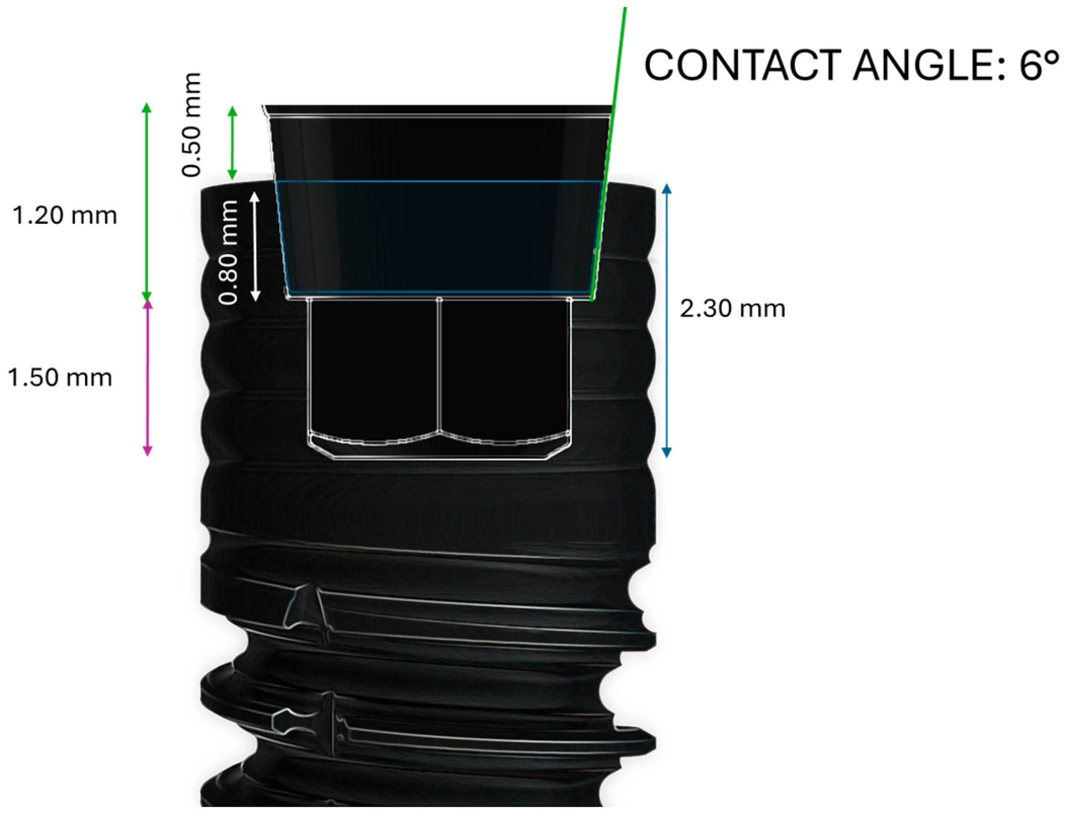
2.1. Dental Implant Characteristics
2.2. Study Design
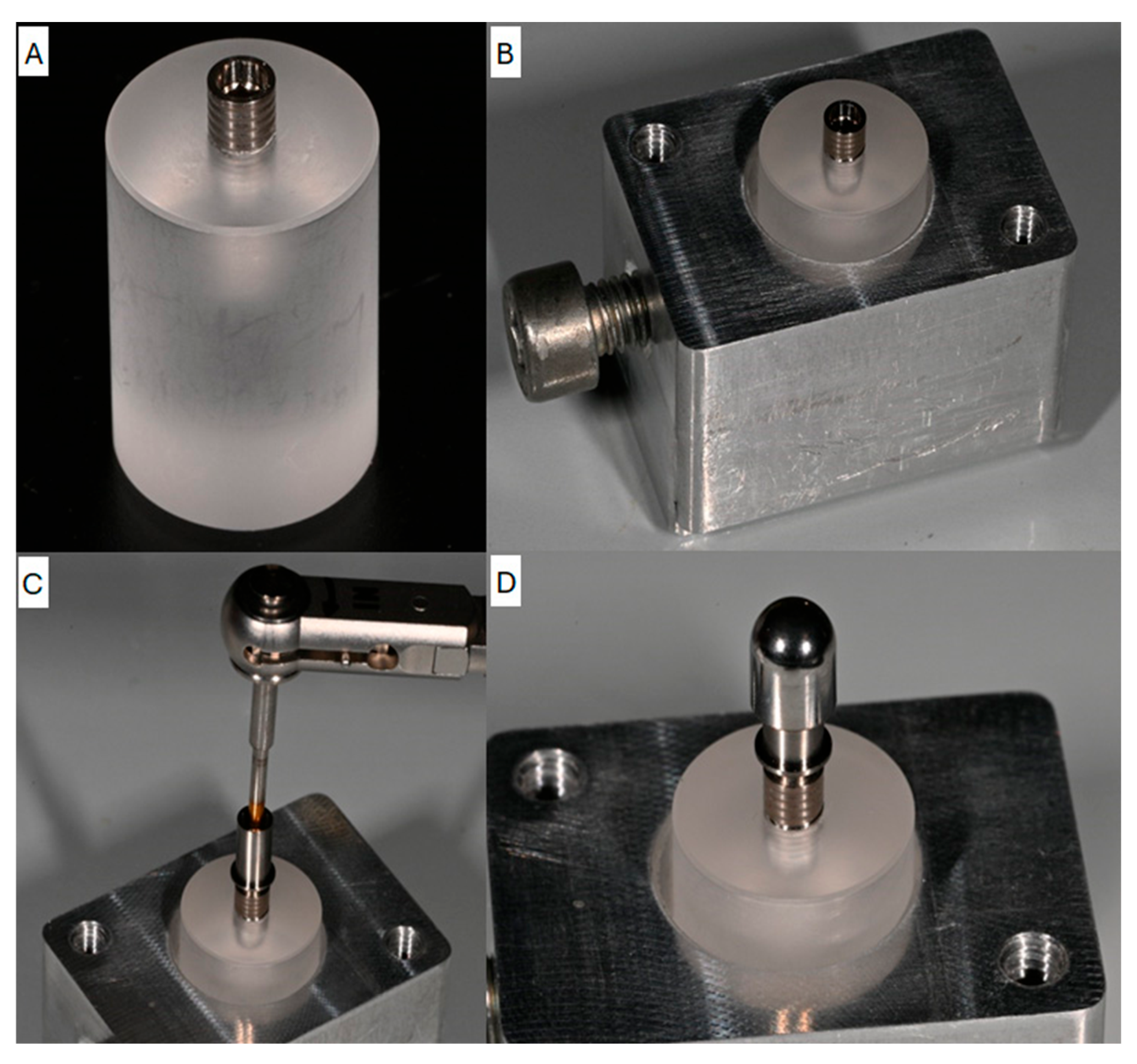
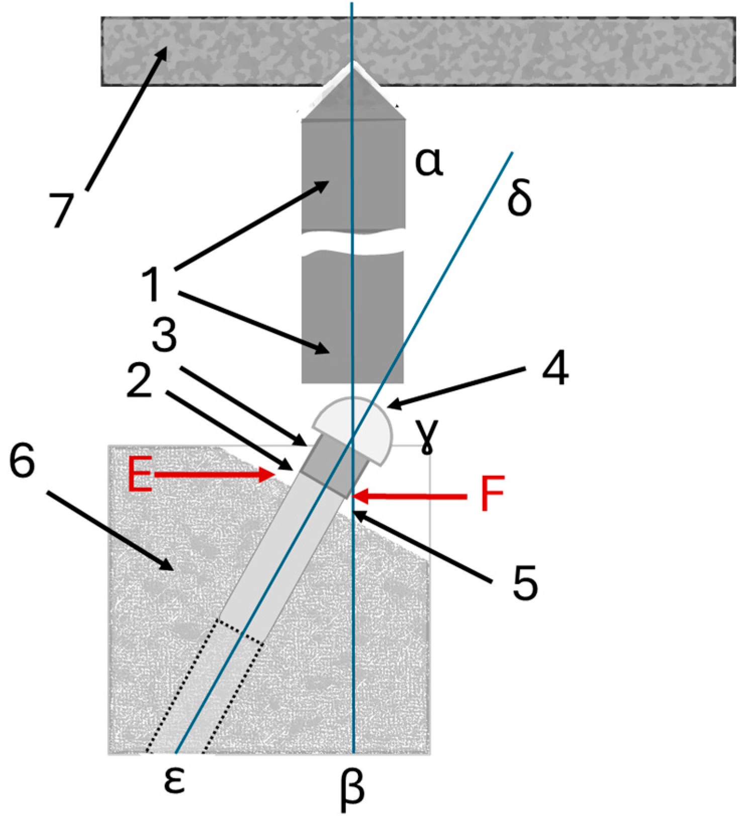
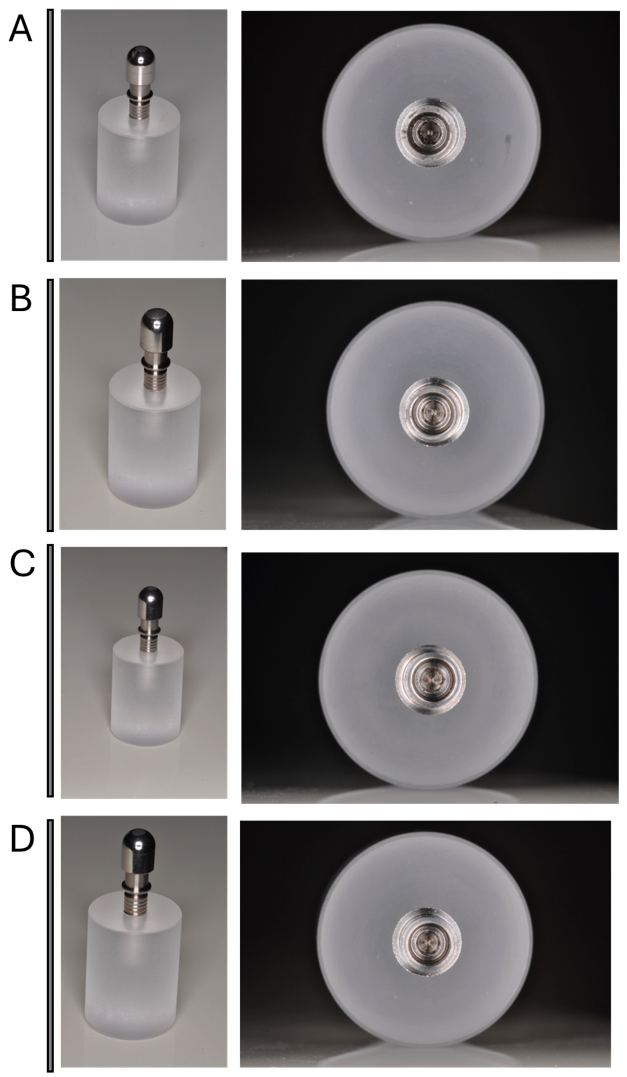
2.3. Testing Set-Up
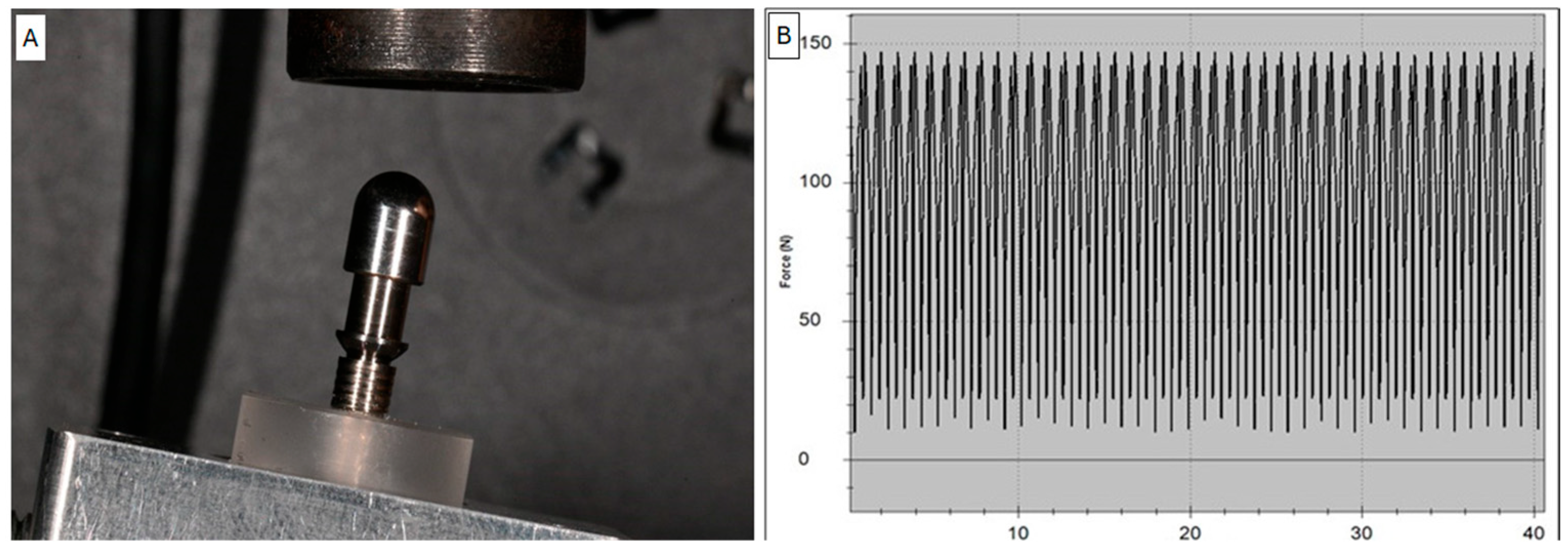
2.4. Test Group Loading Test Details
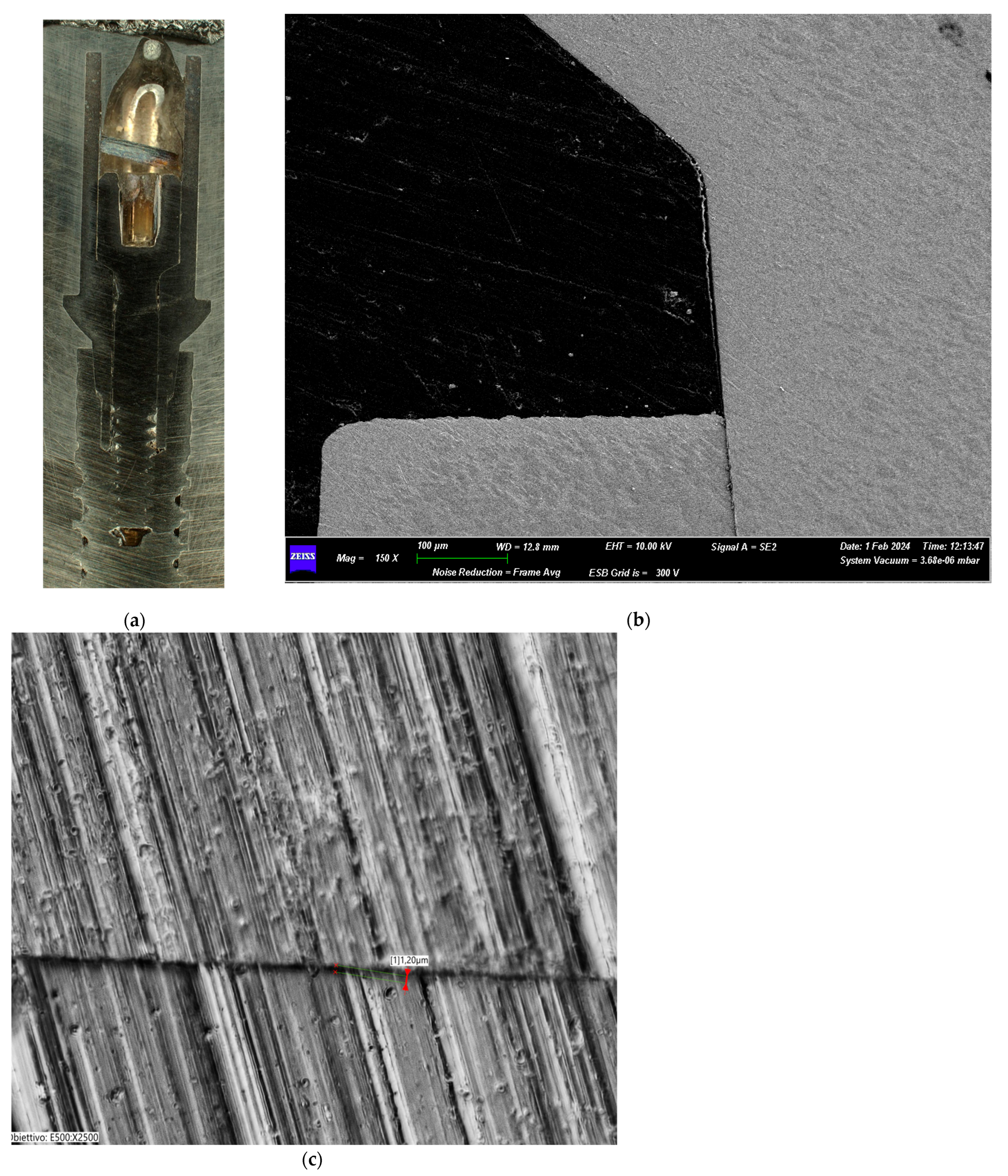
2.5. Scanning Electron Microscopy (SEM) Analysis
2.6. Macroscopic Evaluation
2.7. Statistical Analyses
3. Results
3.1. Macroscopic Evaluation Results of Test Groups
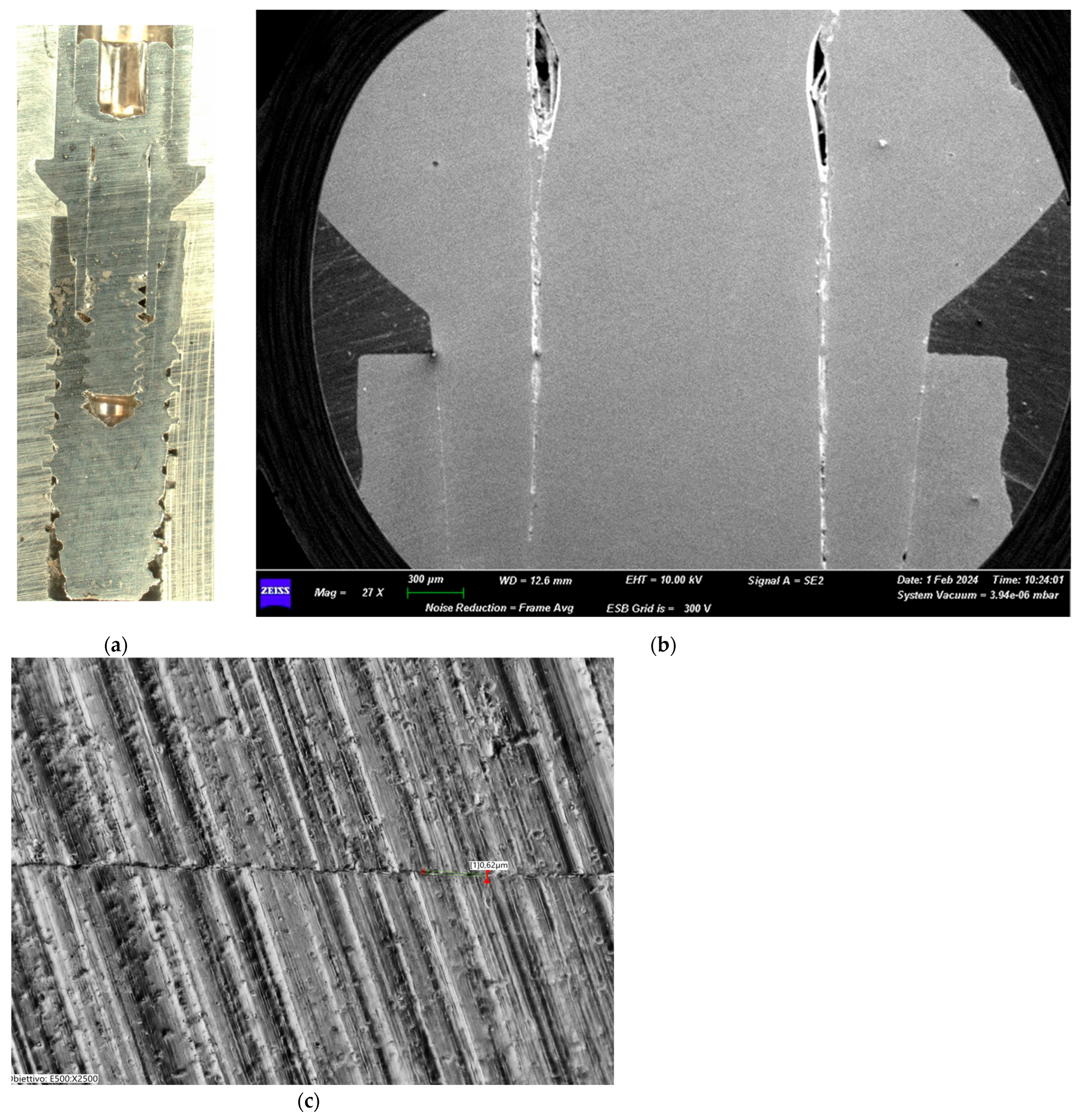
3.1.1. Group I (25 Ncm)
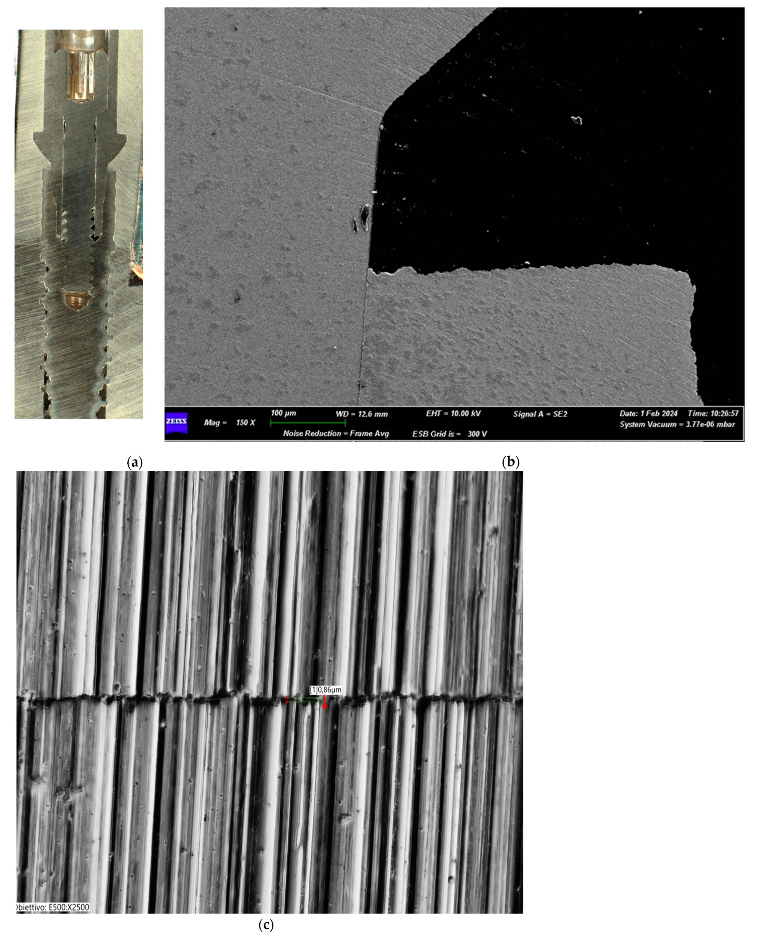
3.1.2. Group II (30 Ncm)
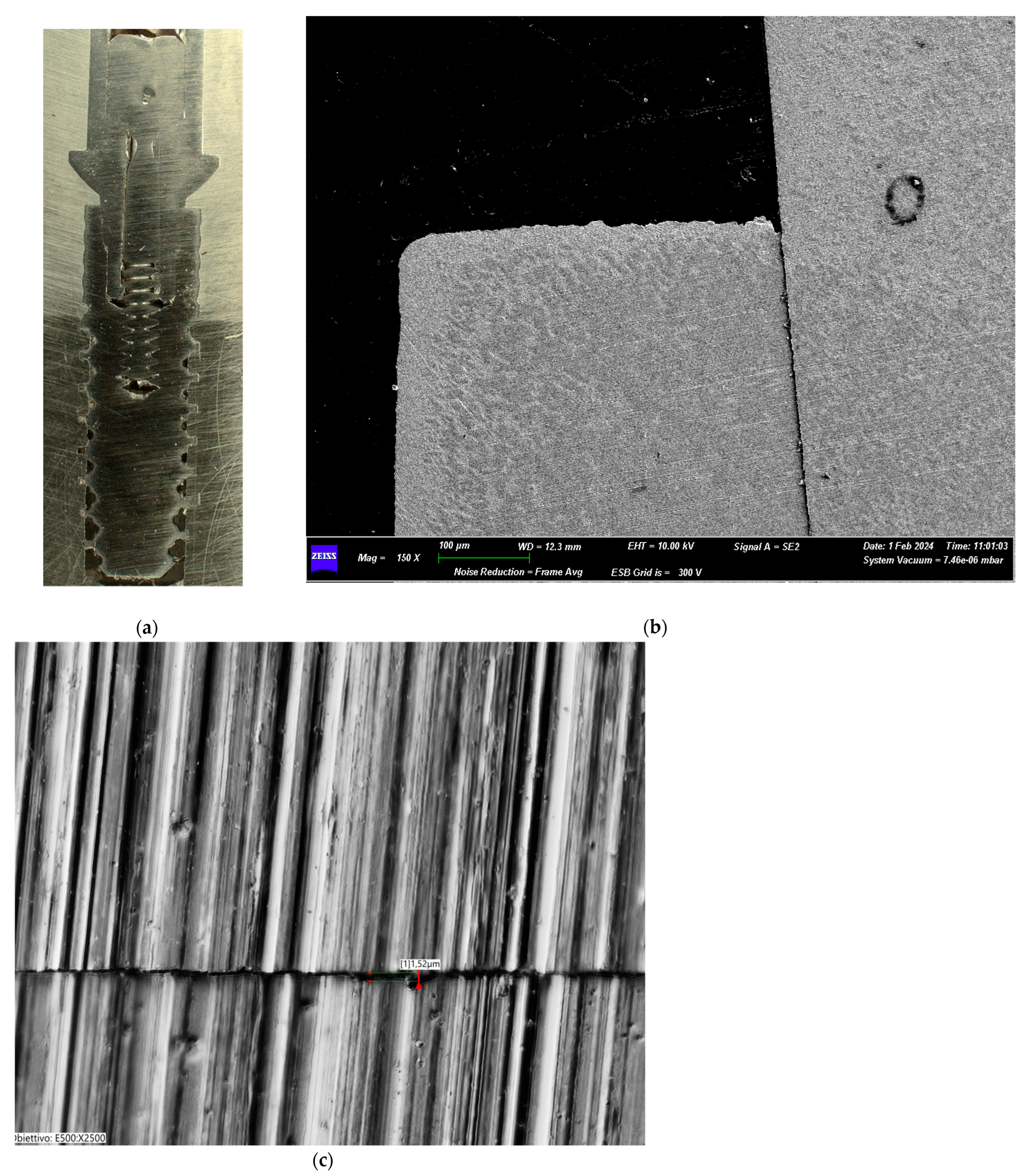
3.1.3. Group III (35 Ncm)
3.1.4. Group IV (40 Ncm)
3.2. Microscopic Observation
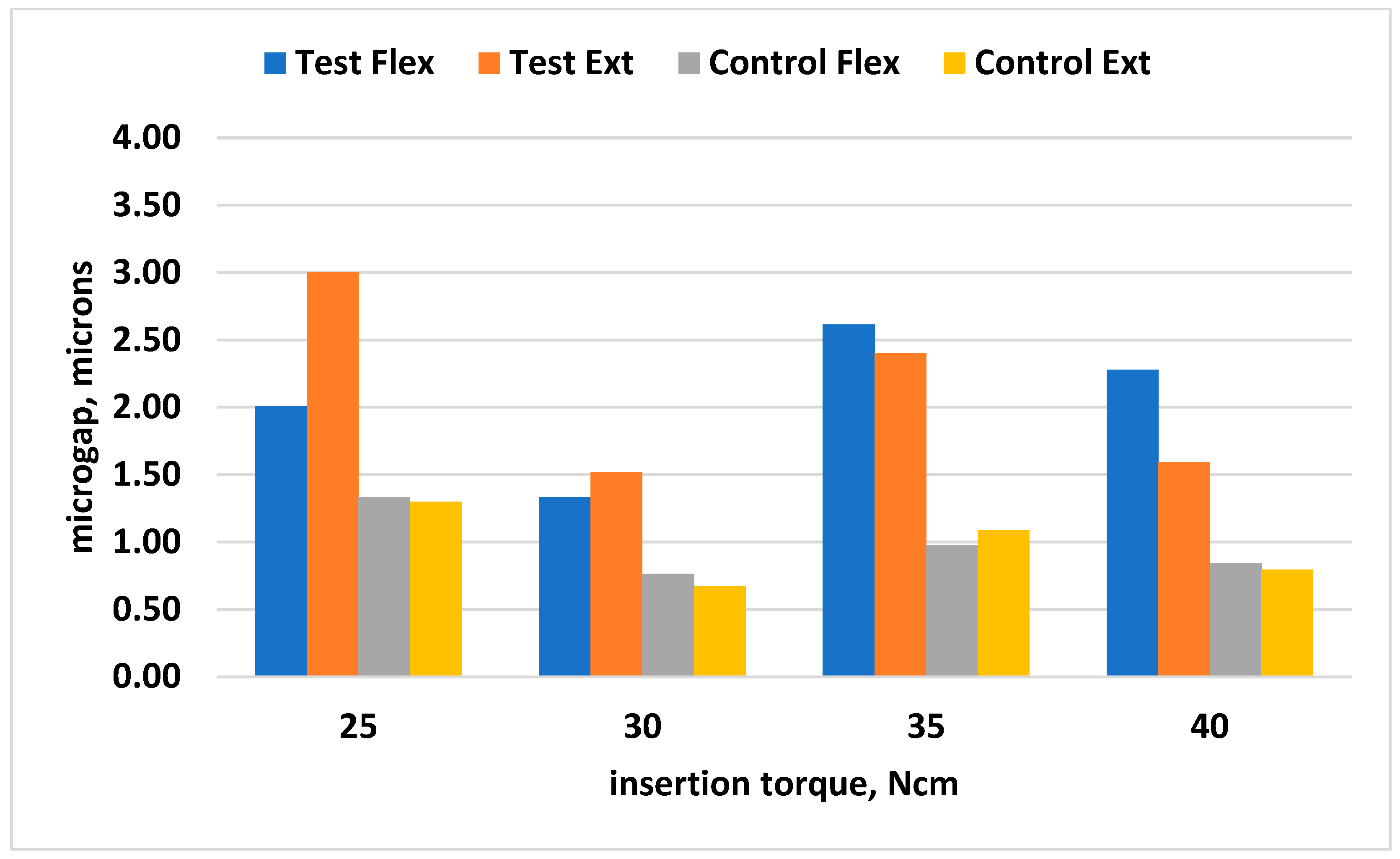
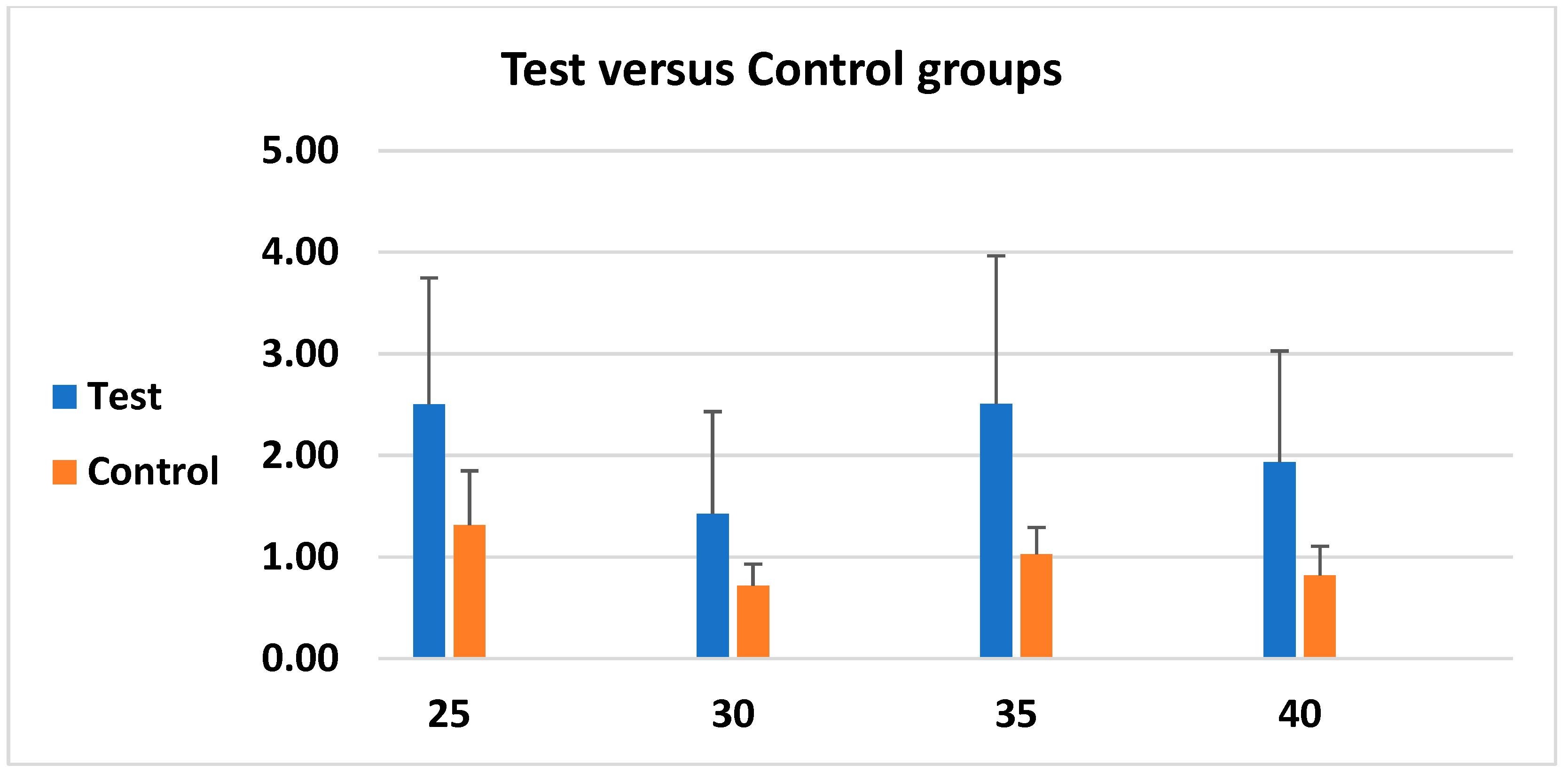
3.3. Microgap-Measurement Results
4. Discussion
5. Conclusions
Author Contributions
Funding
Institutional Review Board Statement
Informed Consent Statement
Data Availability Statement
Acknowledgments
Conflicts of Interest
References
- Albrektsson, T.; Wennerberg, A. On osseointegration in relation to implant surfaces. Clin. Implant. Dent. Relat. Res. 2019, 21, 4–7. [Google Scholar] [CrossRef]
- Albrektsson, T.; Sennerby, L. State of the art in oral implants. J. Clin. Periodontol. 1991, 18, 474–481. [Google Scholar] [CrossRef]
- Moraschini, V.; Poubel, L.A.; Ferreira, V.F.; Barboza Edos, S. Evaluation of survival and success rates of dental implants reported in longitudinal studies with a follow-up period of at least 10 years: A systematic review. Int. J. Oral. Maxillofac. Surg. 2015, 44, 377–388. [Google Scholar] [CrossRef]
- Agustín-Panadero, R.; Serra-Pastor, B.; Roig-Vanaclocha, A.; Fons-Font, A.; Solá-Ruiz, M.F. Fracture resistance and the mode of failure produced in metal-free crowns cemented onto zirconia abutments in dental implants. PLoS ONE 2019, 14, e0220551. [Google Scholar] [CrossRef]
- Arys, A.; Philippart, C.; Dourov, N.; He, Y.; Le, Q.T.; Pireaux, J.J. Analysis of titanium dental implants after failure of osseointegration: Combined histological, electron microscopy, and X-ray photoelectron spectroscopy approach. J. Biomed. Mater. Res. 1998, 43, 300–312. [Google Scholar] [CrossRef]
- Bordin, D.; Bergamo, E.T.P.; Bonfante, E.A.; Fardin, V.P.; Coelho, P.G. Influence of platform diameter in the reliability and failure mode of extra-short dental implants. J. Mech. Behav. Biomed. Mater. 2018, 77, 470–474. [Google Scholar] [CrossRef]
- Mozzati, M.; Arata, V.; Giacomello, M.; Del Fabbro, M.; Gallesio, G.; Mortellaro, C.; Bergamasco, L. Failure risk estimates after dental implants placement associated with plasma rich in growth factor-Endoret in osteoporotic women under bisphosphonate therapy. J. Craniofac. Surg. 2015, 26, 749–755. [Google Scholar] [CrossRef] [PubMed]
- Bello Taborda, M.B.; Yaguinuma Gonçalves, G.S.; Alves de Sousa, C.; Gonçalves Assunção, W. Analysis of Torque Maintenance and Fracture Resistance after Fatigue in Retention Screws Made of Different Metals for Screw-Retained Implant-Borne Prosthesis Joints. Int. J. Dent. 2021, 2021, 9693239. [Google Scholar] [CrossRef] [PubMed]
- Bahuguna, R.; Anand, B.; Kumar, D.; Aeran, H.; Anand, V.; Gulati, M. Evaluation of stress patterns in bone around dental implant for different abutment angulations under axial and oblique loading: A finite element analysis. Natl. J. Maxillofac. Surg. 2013, 4, 46–51. [Google Scholar] [CrossRef] [PubMed]
- Baj, A.; Bolzoni, A.; Russillo, A.; Lauritano, D.; Palmieri, A.; Cura, F.; Silvestre, F.J.; Giannì, A.B. Cone-morse implant connection system significantly reduces bacterial leakage between implant and abutment: An in vitro study. J. Biol. Regul. Homeost. Agents 2017, 31, 203–208. [Google Scholar] [PubMed]
- Bittencourt, A.B.B.C.; Neto, C.L.M.M.; Penitente, P.A.; Pellizzer, E.P.; Dos Santos, D.M.; Goiato, M.C. Comparison of the Morse Cone Connection with the Internal Hexagon and External Hexagon Connections Based on Microleakage—Review. Prague Med. Rep. 2021, 122, 181–190. [Google Scholar] [CrossRef]
- Scarano, A.; Mortellaro, C.; Mavriqi, L.; Pecci, R.; Valbonetti, L. Evaluation of Microgap with Three-Dimensional X-Ray Microtomography: Internal Hexagon Versus Cone Morse. J. Craniofac. Surg. 2016, 27, 682–685. [Google Scholar] [CrossRef]
- Ding, Y.; Zhou, H.; Zhang, W.; Chen, J.; Zheng, Y.; Wang, L.; Yang, F. Evaluation of a platform-switched Morse taper connection for all-on-four or six treatment in edentulous or terminal dentition treatment: A retrospective study with 1–8 years of follow-up. Clin. Implant. Dent. Relat. Res. 2023, 25, 815–828. [Google Scholar] [CrossRef]
- Muley, N.; Prithviraj, D.R.; Gupta, V. Evolution of external and internal implant to abutment connection. Int. J. Oral Implantol. Clin. Res. 2012, 3, 122–129. [Google Scholar] [CrossRef]
- Bavetta, G.; Bavetta, G.; Randazzo, V.; Cavataio, A.; Paderni, C.; Grassia, V.; Dipalma, G.; Gargiulo Isacco, C.; Scarano, A.; De Vito, D.; et al. A Retrospective Study on Insertion Torque and Implant Stability Quotient (ISQ) as Stability Parameters for Immediate Loading of Implants in Fresh Extraction Sockets. BioMed. Res. Int. 2019, 2019, 9720419. [Google Scholar] [CrossRef] [PubMed]
- Lorusso, F.; Alla, I.; Gehrke, S.A.; Carmine, M.D.; Tari, S.R.; Scarano, A. Effect of Different Dental Implant Prosthetic Joints on Marginal Bone Loss: Emerging Findings from a Bayesian Network Meta-Analysis (NMA) and Systematic Review. Prosthesis 2024, 6, 186–205. [Google Scholar] [CrossRef]
- Fuda, S.; Martins, B.G.d.S.; Castro, F.C.d.; Heboyan, A.; Gehrke, S.A.; Fernandes, J.C.H.; Mello-Moura, A.C.V.; Fernandes, G.V.O. Marginal Bone Level and Clinical Parameter Analysis Comparing External Hexagon and Morse Taper Implants: A Systematic Review and Meta-Analysis. Diagnostics 2023, 13, 1587. [Google Scholar] [CrossRef]
- Silva, G.A.F.; Faot, F.; Possebon, A.P.D.R.; da Silva, W.J.; Del Bel Cury, A.A. Effect of macrogeometry and bone type on insertion torque, primary stability, surface topography damage and titanium release of dental implants during surgical insertion into artificial bone. J. Mech. Behav. Biomed. Mater. 2021, 119, 104515. [Google Scholar] [CrossRef]
- Caballero, C.; Rodriguez, F.; Cortellari, G.C.; Scarano, A.; Prados-Frutos, J.C.; De Aza, P.N.; Fernandes, G.V.O.; Gehrke, S.A. Mechanical Behavior of Five Different Morse Taper Implants and Abutments with Different Conical Internal Connections and Angles: An In Vitro Experimental Study. J. Funct. Biomater. 2024, 15, 177. [Google Scholar] [CrossRef]
- Yao, K.T.; Kao, H.C.; Cheng, C.K.; Fang, H.W.; Huang, C.H.; Hsu, M.L. The Potential Risk of Conical Implant-Abutment Connections: The Antirotational Ability of Cowell Implant System. Clin. Implant. Dent. Relat. Res. 2015, 17, 1208–1216. [Google Scholar] [CrossRef]
- Juan-Montesinos, A.; Agustín-Panadero, R.; Solá-Ruiz, M.F.; Marco-Pitarch, R.; Montiel-Company, J.M.; Fons-Badal, C. Comparative Study by Systematic Review and Meta-Analysis of the Peri-Implant Effect of Two Types of Platforms: Platform-Switching versus Conventional Platforms. J. Clin. Med. 2022, 11, 1743. [Google Scholar] [CrossRef] [PubMed]
- Greenstein, G.; Albeshri, S.; Majeed-Saidan, A. Surgical and prosthetic criteria for selecting prefabricated vs custom implant abutments. Gen. Dent. 2025, 73, 20–26. [Google Scholar]
- Misch, J.; Alrmali, A.E.; Galindo-Fernandez, P.; Saleh, M.H.A.; Wang, H.L. Peri-implant tissue stability: The PROS concept. Int. J. Oral Implantol. 2025, 18, 73–84. [Google Scholar] [PubMed]
- Salama, A.A.; Katamish, H.A.; Halim, C.H.; Farid, K.A. The mechanical complications of platform switching connection on implant supported restorations: A systematic review and meta-analysis. J. Osseointegr. 2019, 11, 3. [Google Scholar] [CrossRef]
- Duyck, J.; Naert, I. Failure of oral implants: Aetiology, symptoms and influencing factors. Clin. Oral Investig. 1998, 2, 102–114. [Google Scholar] [CrossRef]
- de Oliveira, R.R.; Novaes, A.B., Jr.; Taba, M., Jr.; Papalexiou, V.; Muglia, V.A. Bone remodeling adjacent to Morse cone-connection implants with platform switch: A fluorescence study in the dog mandible. Int. J. Oral Maxillofac. Implant. 2009, 24, 257–266. [Google Scholar]
- Degidi, M.; Daprile, G.; Piattelli, A. Marginal bone loss around implants with platform-switched Morse-cone connection: A radiographic cross-sectional study. Clin. Oral Implant. Res. 2017, 28, 1108–1112. [Google Scholar] [CrossRef]
- Angeles Maslucan, R.; Dominguez, J.A. A Finite Element Stress Analysis of a Concical Triangular Connection in Implants: A New Proposal. Materials 2022, 15, 3680. [Google Scholar] [CrossRef]
- Larrucea Verdugo, C.; Jaramillo Núñez, G.; Acevedo Avila, A.; Larrucea San Martín, C. Microleakage of the prosthetic abutment/implant interface with internal and external connection: In vitro study. Clin. Oral Implant. Res. 2014, 25, 1078–1083. [Google Scholar] [CrossRef] [PubMed]
- Gehrke, S.A.; Delgado-Ruiz, R.A.; Prados Frutos, J.C.; Prados-Privado, M.; Dedavid, B.A.; Granero Marín, J.M.; Calvo Guirado, J.L. Misfit of Three Different Implant-Abutment Connections Before and After Cyclic Load Application: An In Vitro Study. Int. J. Oral Maxillofac. Implants 2017, 32, 822–829. [Google Scholar] [CrossRef]
- Sun, F.; Cheng, W.; Zhao, B.; Lin, Z. Fatigue properties of plasma nitriding for dental implant application. J. Prosthet. Dent. 2024, 131, 329.e1–329.e8. [Google Scholar] [CrossRef] [PubMed]

| Kruskal–Wallis Test | Test Flexion | Test Extension | Control Flexion | Control Extension |
|---|---|---|---|---|
| p value | * 0.0121 | * 0.0027 | ** 0.0337 | ** 0.0021 |
| Significance | * | ** | * | ** |
| Do the medians vary significantly (p < 0.05) | Yes | Yes | Yes | Yes |
| Kruskal–Wallis statistic | 10.93 | 14.17 | 8.693 | 14.66 |
| Dunn’s Multiple Comparison Test | Difference in Rank Sum | Significance | Difference in Rank Sum | Significance | Difference in Rank Sum | Significance | Difference in Rank Sum | Significance |
|---|---|---|---|---|---|---|---|---|
| Test Flexion | Test Extension | Control Flexion | Control Extension | |||||
| 25 vs. 30 Ncm | 9.050 | ns | 18.1 | ** | 13.95 | * | 17.65 | ** |
| 25 vs. 35 Ncm | −7.550 | ns | 8.85 | ns | 3.9 | ns | 2.65 | ns |
| 25 vs. 40 Ncm | −3.300 | ns | 15.25 | * | 10.15 | ns | 11.5 | ns |
| 30 vs. 35 Ncm | −16.60 | ** | −9.25 | ns | −10.05 | ns | −15 | * |
| 30 vs. 40 Ncm | −12.35 | ns | −2.85 | ns | −3.8 | ns | −6.15 | ns |
| 35 vs. 40 Ncm | 4.250 | ns | 6.4 | ns | 6.25 | ns | 8.85 | ns |
| Implant–Abutment Connection Types | Properties | Advantages | Disadvantages |
|---|---|---|---|
| Internal connection [23] | Abutments with a connection feature that extends inferior to the coronal portion of the implant | Improved aesthetics Less screw loosening Better microbial seal Better joint strength More platform switching options | The weakest link is the bone rather than the retaining prosthetic screw Less literature on internal connections than external connections |
| External hexagonal connection [17] | Abutments with an external connection with anti-rotational and indexing features | More scientific literature with long-term follow-up data Compatibility among multiple implant systems Solutions to complications are well investigated due to extensive use | Higher prevalence of screw loosening Higher rates of rotational misfit Fewer aesthetic results Inadequate microbial seal |
| Platform Switching [21,24] | The diameter of the abutment is narrower than that of the implant. The connection can be both internal and external (more frequently used for internal connection) | Decrease in the stresses around the implant–abutment interface Increase in the forces around the abutment, which results in a decrease of crestal bone loss | Potential lower fracture strength values Increased stress on the abutment and fixation screw The possibility of component maladjustment, screw loosening or fracture Higher costs associated with specialized components to ensure proper component compatibility The learning curve for clinicians is more difficult |
| Cone screw [20] | Screw with a conical head that allows for a tight fit | Lower marginal bone loss and reduced prosthetic complications | Insufficient tightness under lateral forces (particularly those with shallow taper angles), leading to micromovements and potential bacterial infiltration This can result in higher risk of screw loosening, abutment fracture and marginal bone loss |
| Morse taper designs [17,19] | Conical connection that involves a trunnion and a bore portion that are both tapered, creating a tight friction fit mechanism. This mechanism occurs when the conical pillar is installed in a conical cavity, generating significant friction due to the parallelism of two structures. | Enhanced stability Reduced micro-movements Therefore, this better fit between the pieces favors joint action, improving the distribution of chewing forces | The potential for abutment fracture and the need for specialized expertise in placement and fitting due to the tight connection |
| Custom-made abutments [22] | A metal connector (titanium or gold-toned titanium) fabricated by a dental lab to fit an individual’s unique dental implant and occlusion | Custom-made dental implant–abutments offer advantages like superior aesthetics, a more natural feel and improved tissue health | Higher cost and longer processing time compared to stock abutments |
Disclaimer/Publisher’s Note: The statements, opinions and data contained in all publications are solely those of the individual author(s) and contributor(s) and not of MDPI and/or the editor(s). MDPI and/or the editor(s) disclaim responsibility for any injury to people or property resulting from any ideas, methods, instructions or products referred to in the content. |
© 2025 by the authors. Licensee MDPI, Basel, Switzerland. This article is an open access article distributed under the terms and conditions of the Creative Commons Attribution (CC BY) license (https://creativecommons.org/licenses/by/4.0/).
Share and Cite
Lorusso, F.; Scarano, A.; Tari, S.R.; Singhal, I.; Goker, F.; Soldini, M.C.; Tartaglia, G.M.; Del Fabbro, M. The Effect of Different Tightening Torques of Implant Cone Morse Abutment Connection Under Dynamic Fatigue Loading: An In Vitro Study. Biomimetics 2025, 10, 511. https://doi.org/10.3390/biomimetics10080511
Lorusso F, Scarano A, Tari SR, Singhal I, Goker F, Soldini MC, Tartaglia GM, Del Fabbro M. The Effect of Different Tightening Torques of Implant Cone Morse Abutment Connection Under Dynamic Fatigue Loading: An In Vitro Study. Biomimetics. 2025; 10(8):511. https://doi.org/10.3390/biomimetics10080511
Chicago/Turabian StyleLorusso, Felice, Antonio Scarano, Sergio Rexhep Tari, Ishita Singhal, Funda Goker, Maria Costanza Soldini, Gianluca Martino Tartaglia, and Massimo Del Fabbro. 2025. "The Effect of Different Tightening Torques of Implant Cone Morse Abutment Connection Under Dynamic Fatigue Loading: An In Vitro Study" Biomimetics 10, no. 8: 511. https://doi.org/10.3390/biomimetics10080511
APA StyleLorusso, F., Scarano, A., Tari, S. R., Singhal, I., Goker, F., Soldini, M. C., Tartaglia, G. M., & Del Fabbro, M. (2025). The Effect of Different Tightening Torques of Implant Cone Morse Abutment Connection Under Dynamic Fatigue Loading: An In Vitro Study. Biomimetics, 10(8), 511. https://doi.org/10.3390/biomimetics10080511