

An Intuitive and Efficient Teleoperation Human–Robot Interface Based on a Wearable Myoelectric Armband

Abstract
1. Introduction
2. Materials and Methods
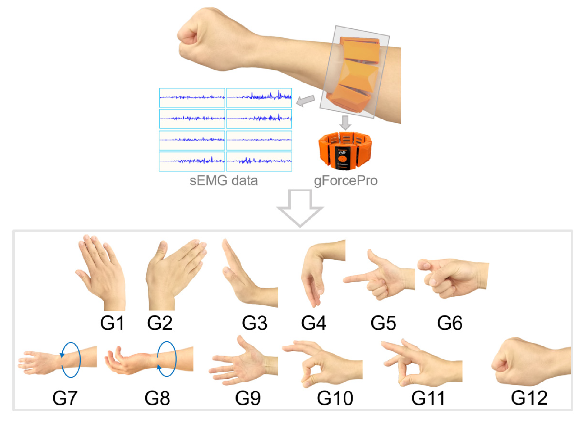
2.1. Wearable Myoelectric Armband Interface
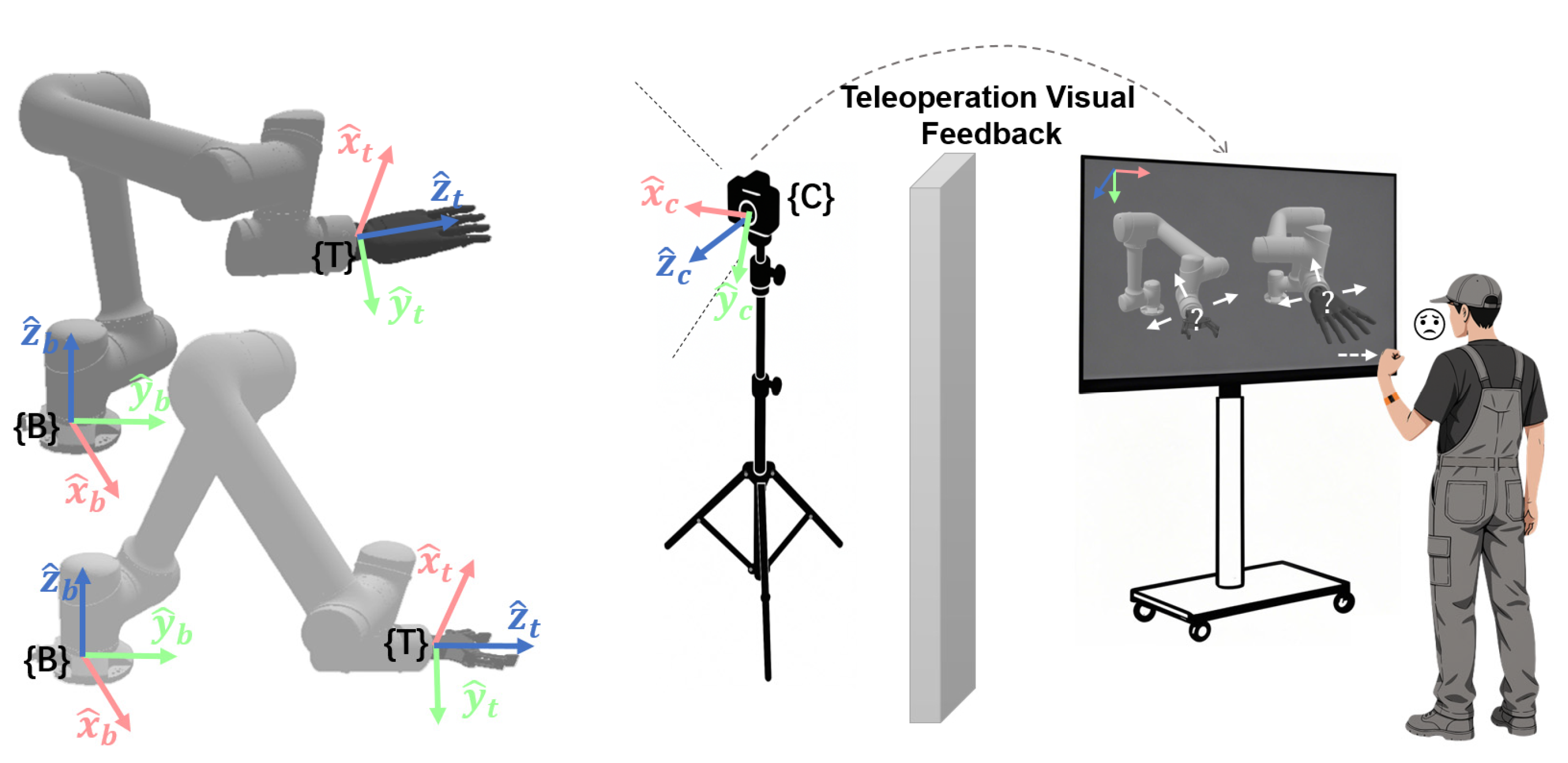
2.2. Hybrid Reference Frame Selection Based on Visual-Motor Misalignment Quantification
2.2.1. Quantification of Visual-Motor Misalignment
2.2.2. Analysis of Control Reference Frame Selection
- (1)
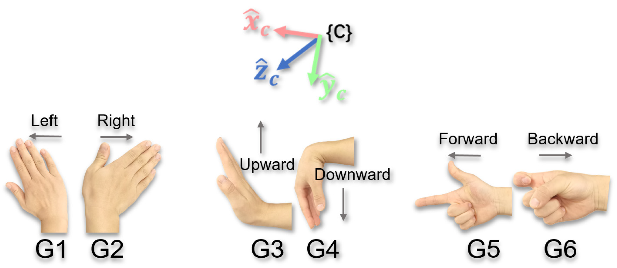
- Selection of Translational Reference FrameTaking gesture G2 as an example, suppose the intended motion produced by this gesture is the end-effector motion horizontally to the right on the screen, i.e., (expressed in the {C} frame, representing the motion direction the operator expects to observe on the screen). The analysis of the three reference frames is as follows:
- (a)
- Base Reference Frame {B}
Gesture G2 triggers the end-effector to translate along the -axis of {B}, with the direction vector in the {B} frame. The actual motion direction feedback on the screen is . represents the rotation matrix from {B} to {C} (obtained through hand–eye calibration). According to Equation (1), the misalignment metric is . Therefore, when the -axis is aligned with the -axis, . However, if the camera view deviates, for example, by rotating around the -axis by an angle (), then , i.e., . This indicates that when {B} is chosen as the control reference frame, visual misalignment of translational motion will occur unless {C} is perfectly aligned with {B}.- (b)
- Tool Reference Frame {T}
Gesture G2 triggers the end-effector to translate along the -axis of {T}, with the direction vector in the {T} frame. The actual motion direction is (). is the robot pose matrix (obtained through the robot’s forward kinematics). The misalignment metric is . Since the orientation of {T} dynamically changes with the end-effector while the orientation of {C} is fixed, visual misalignment (i.e., ) will occur unless the -axis is aligned with the -axis.- (c)
- Camera Reference Frame {C}
Gesture G2 triggers the end-effector to translate along the -axis of {C}, with the direction vector in the {C} frame. In this case, and coincide, i.e., . The axis of {C} is directly aligned with the screen’s directions (horizontal, vertical, depth), and no matter how the camera view changes, visual misalignment of translational motion will never occur.
- (2)
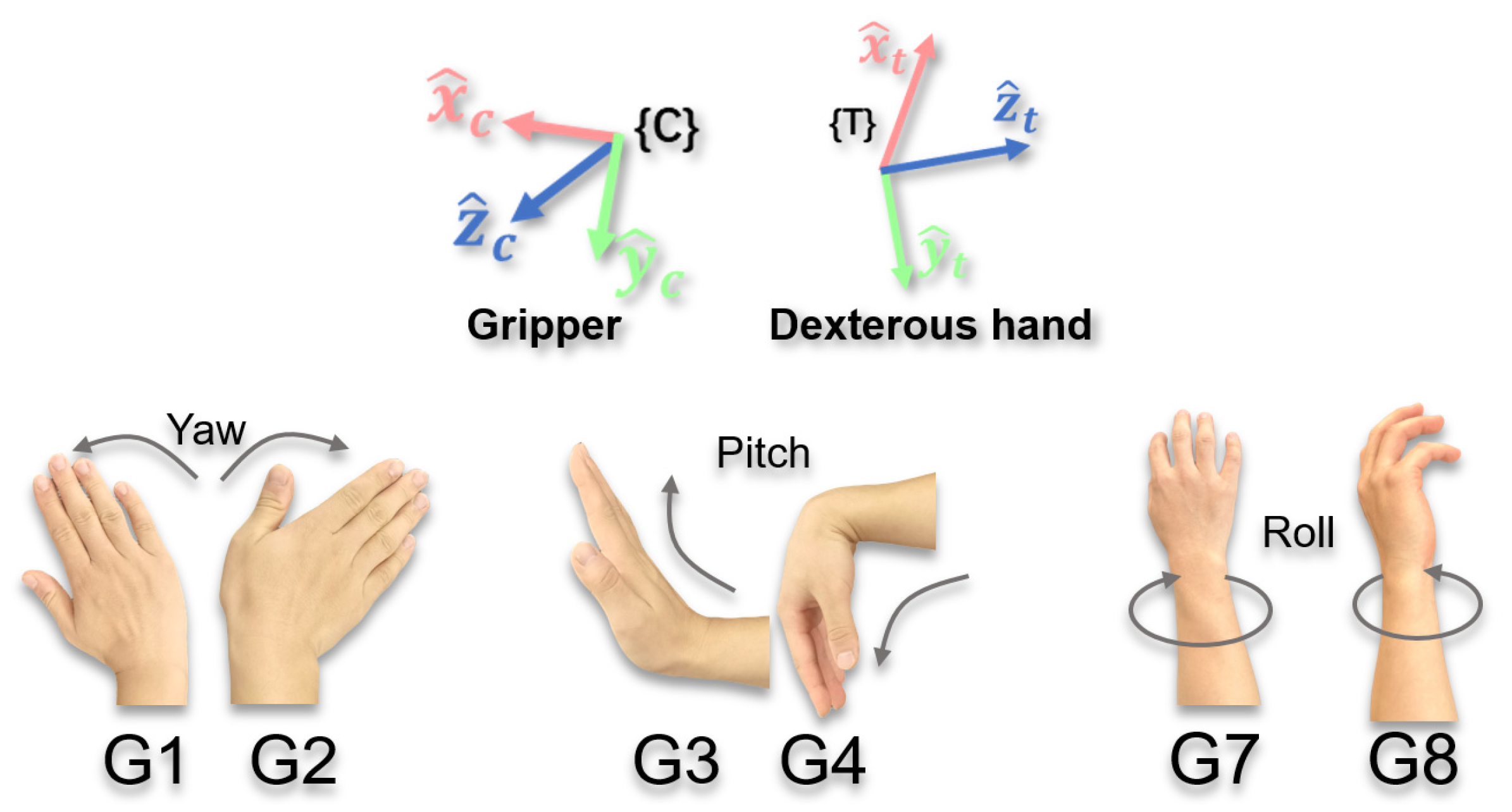
- Selection of Rotational Reference FrameTaking gestures G7/G8 (triggering roll) as an example, the user’s expectations may be based on the screen perspective (e.g., around the -axis of {C}) or the end-effector itself (e.g., around the -axis of {T}), depending on the task requirements and the type of end-effector. The analysis of the three reference frames is as follows:
- (a)
- Base Reference Frame {B}
Gesture G7 or G8 triggers the end-effector to rotate around the -axis of {B}. The rotation axis in {B} is . The actual rotation axis feedback on the screen is . If the expected rotation is around the screen’s depth direction, then . According to Equation (2), the misalignment metric is . Unless the -axis is aligned with the -axis, . If the expected rotation is around the end-effector’s -axis, , and obviously , unless the -axis is aligned with the -axis. Therefore, the fixed nature of {B} makes it difficult to adapt to changes in viewpoint or end-effector orientation, and the rotation feedback often deviates from the expected direction.- (b)
- Tool Reference Frame {T}
Gesture G7 or G8 triggers the end-effector to rotate around the -axis of {T}. The rotation axis in {T} is . The actual rotation axis is . If the expected rotation is around the screen depth direction, , then . Typically, , unless the -axis is aligned with the -axis. If the expected rotation is around the end-effector’s -axis, then , so . Therefore, {T} is intuitive for local rotations of the end-effector, but may lead to misalignment in tasks based on the screen perspective.- (c)
- Camera Reference Frame {C}
Gesture G7 or G8 triggers the end-effector to rotate around the -axis of {C}, i.e., . If the expected rotation is around the screen depth direction, , then . If the expected rotation is around the end-effector’s -axis, , then . Unless the -axis is aligned with the -axis, . Therefore, {C} is intuitive in tasks dominated by the screen perspective, but may not be suitable for local rotations of the end-effector.
2.2.3. Hybrid Reference Frame Design
2.3. Finite State Machine-Based Motion Control Logic
- (1)
- Multi-mode switching: Provide multiple operation modes (e.g., translation/rotation, coarse/fine adjustments) to suit different task scenarios and reduce the physical workload on the operator.
- (2)
- Multi-degree-of-freedom cooperative control: Support multi-degree-of-freedom motion of the end-effector through gesture combinations, enhancing operational coherence and efficiency.
- (3)
- Dynamic speed adjustment: Allow operators to adjust motion speed in real-time according to task requirements, increasing control flexibility and adaptability.
2.3.1. Gesture Function Classification and Motion Mode Definition
- (1)
- Translational Motion Mode: Adjusts the end-effector’s position using gestures G1–G6.
- (2)
- Rotational Motion Mode: Adjusts the end-effector’s orientation using gestures G1–G4 and G7–G8.
- (1)
- Progressive Coarse Adjustment: After executing a single gesture command, the robot sustains motion after a single gesture, freeing the operator from continuously holding the pose. During this phase, multi-degree-of-freedom synthesis and dynamic speed adjustment are supported (repeated gestures accelerate the movement, while reverse gestures decelerate it). This mode is suitable for controlling the end-effector’s rapid, large-range movements.
- (2)
- Continuous Fine Adjustment: The gesture continuously drives the end-effector along a single degree of freedom, with the movement stopping when the gesture is released. The speed remains fixed, making it suitable for small-range, high-precision adjustments.
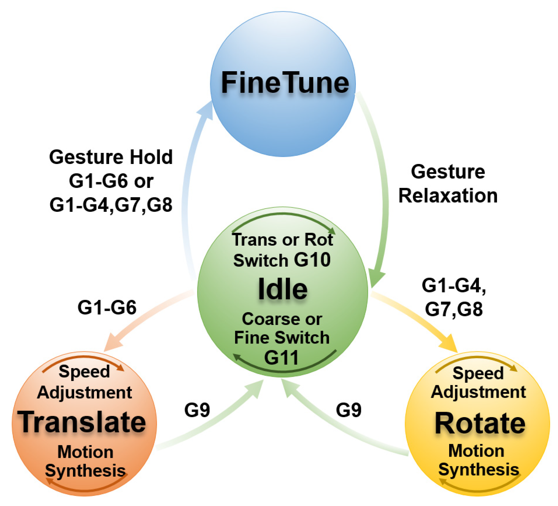
2.3.2. Finite State Machine Design
- (1)
- Idle (Initial State)Description:The system is in its initial or paused state, and the end-effector remains stationary.Parameters:Default motion mode: Translational ModeDefault control mode: Fine Adjustment ModeOperational Mechanism:
- (a)
- The end-effector remains stationary and serves as a hub for mode switching and state transitions.
- (b)
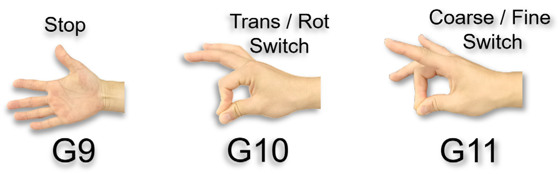
- G10 and G11 adjust the current mode to prepare for subsequent state transitions
Transition Rules:G9: Remains in the Idle state.G10: Switches the motion mode (Translation/Rotation).G11: Switches the control mode (Coarse Adjustment/Fine Adjustment).- (a)
- If the current mode is Coarse Translation: G1–G6 transitions to the Translate state.
- (b)
- If the current mode is Coarse Rotation: G1–G4, G7–G8 transitions to the Rotate state.
- (c)
- If the current mode is Fine Translation: G1–G6 transitions to the FineTune state.
- (d)
- If the current mode is Fine Rotation: G1–G4, G7–G8 transitions to the FineTune state.
- (2)
- Translate (Progressive Coarse Translation State)Description:The end-effector translates along the axes of the camera reference frame {C}, supporting multi-degree-of-freedom synthesis and speed adjustments.Parameters:Translation increment: , , .Base step size: .Operational Mechanism:
- (a)
- Multi-degree-of-freedom synthesis: Different gestures overlay to generate composite motion. For example, G1 followed by G3 results in = (,, 0).
- (b)
- Speed adjustment: Repeated gestures accelerate the movement (e.g., G1 followed by G1 results in = (, 0, 0)), while reverse gestures decelerate it (e.g., G1 followed by G1 then G2 results in = (, 0, 0)).
- (c)
- Motion update: .Transition Rules:G1–G6: Self-loop, adjust translation speed, and motion composition.G9: Return to the Idle state and maintain the translational coarse adjustment mode.
- (3)
- Rotate (Progressive Coarse Rotation State)Description:The end-effector rotates along the axes of the selected reference frame ({C} or {T}), supporting multi-degree-of-freedom motion synthesis and speed adjustments.Parameters:Rotation increment: , , .Base step size: .Operational Mechanism:
- (a)
- Multi-degree-of-freedom synthesis and speed adjustment logic is similar to that of Translate.
- (b)
- Motion update: Gripper (using {C} frame) is =. Dexterous Hand (using {T} frame) is .
Transition Rules:G1–G4, G7–G8: Self-loop, adjust rotation speed, and motion composition.G9: Return to the Idle state and maintain the rotation coarse adjustment mode. - (4)
- FineTune (Continuous Fine Adjustment State)Description:The gesture continuously drives the end-effector’s movement along a single degree of freedom, and motion ceases upon gesture release.Parameters:Motion speed: Fixed small step size ( and ).Operational Mechanism:Movement continues as long as the gesture is held, and stops once the gesture is released.Transition Rules:Based on the motion mode from the Idle state (Fine Translation or Fine Rotation), apply G1–G6 or G1–G4, G7–G8 gestures.
2.3.3. Feedback Mechanism
3. Experiments
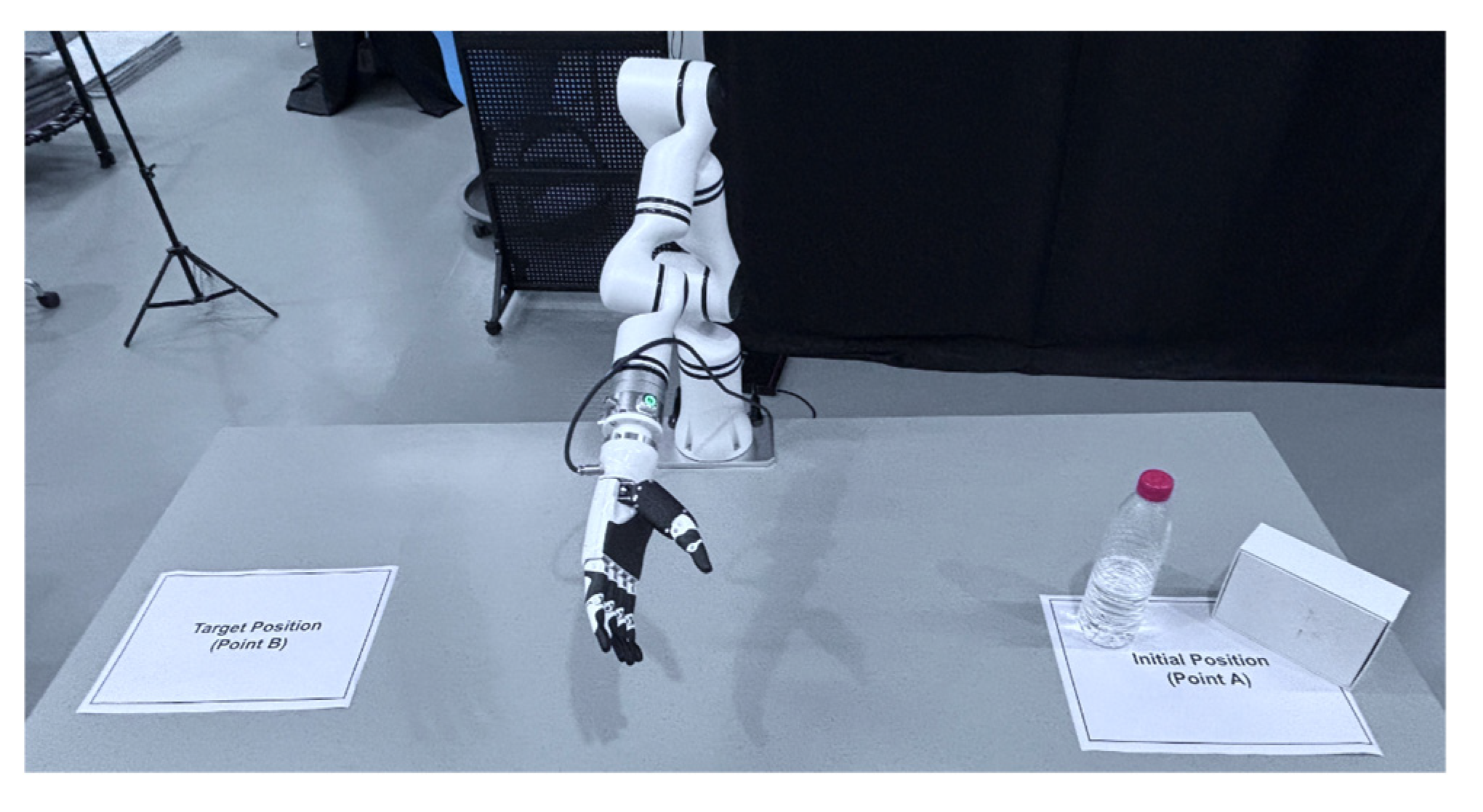
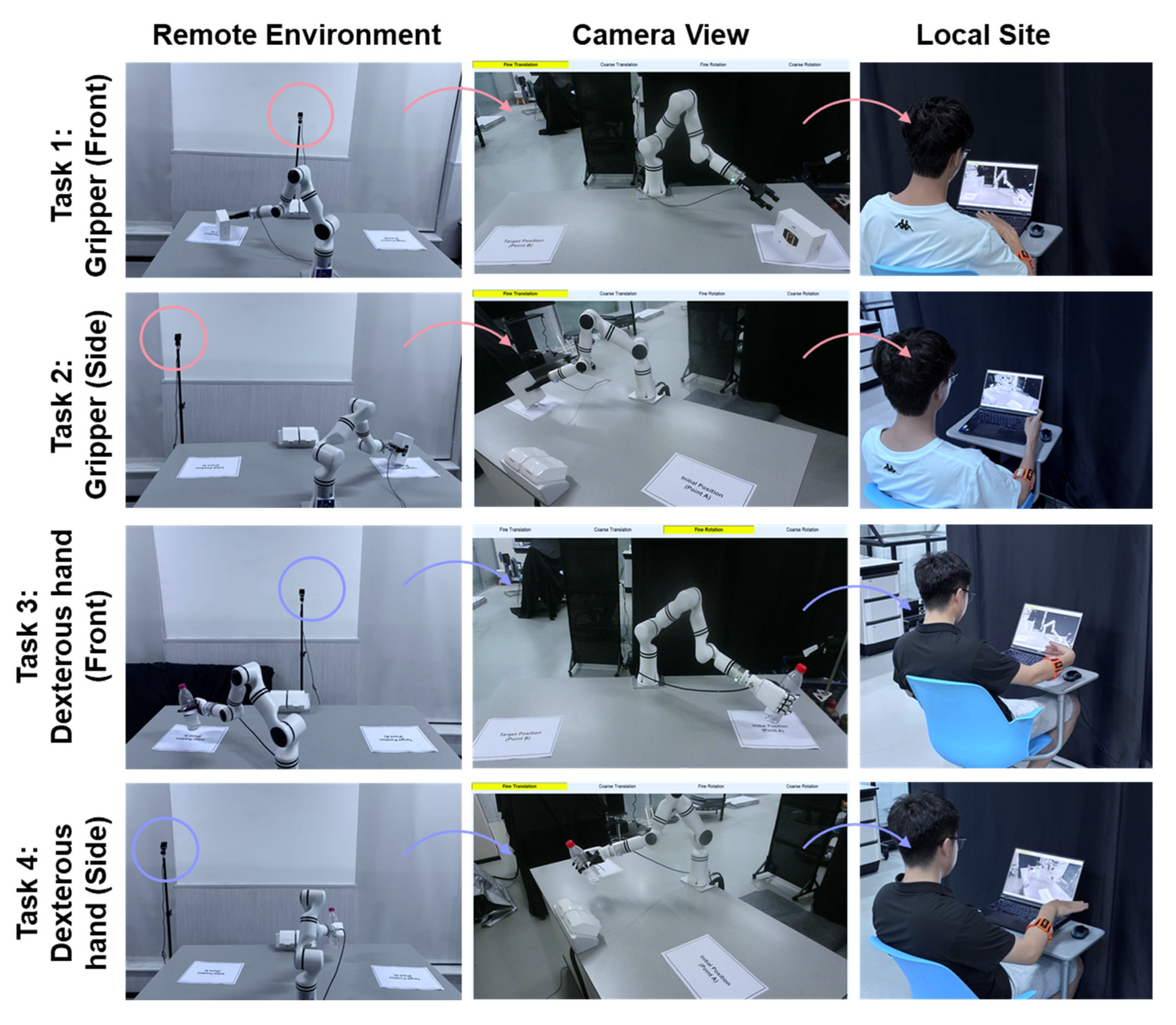
3.1. Experimental Setup
3.2. Experimental Tasks
3.3. Comparison Methods
3.4. Participants
3.5. Evaluation Metrics
3.5.1. Objective Metrics
- (1)
- Task Completion Time (s): The total time from when the operator issues the first valid control command to when the item is successfully placed in the target area. A shorter time indicates higher operational efficiency.
- (2)
- Translational Path (m): The cumulative translation distance traveled by the end-effector in three-dimensional space during the task. A shorter path generally indicates more precise control, fewer redundant movements, and higher intuitiveness.
- (3)
- Rotational Path (rad): The cumulative rotation angle of the end-effector’s orientation during the task. A smaller value indicates more efficient and direct posture adjustments.
3.5.2. Subjective Metrics
3.6. Experimental Procedure
3.6.1. Preparation Phase
3.6.2. Training Phase
- (1)
- Experiment Introduction: The purpose, procedure, and evaluation metrics of the experiment were thoroughly explained to the participants.
- (2)
- Gesture Practice: Participants were guided to practice the execution of gestures for at least 5 min, enabling them to perform the 12 gestures proficiently.
- (3)
- Control Method Practice: Participants were instructed to practice robot motion control for at least 10 min using the methods described in Section 3.3, familiarizing themselves with the operational process of each method.
3.6.3. Execution Phase
4. Results
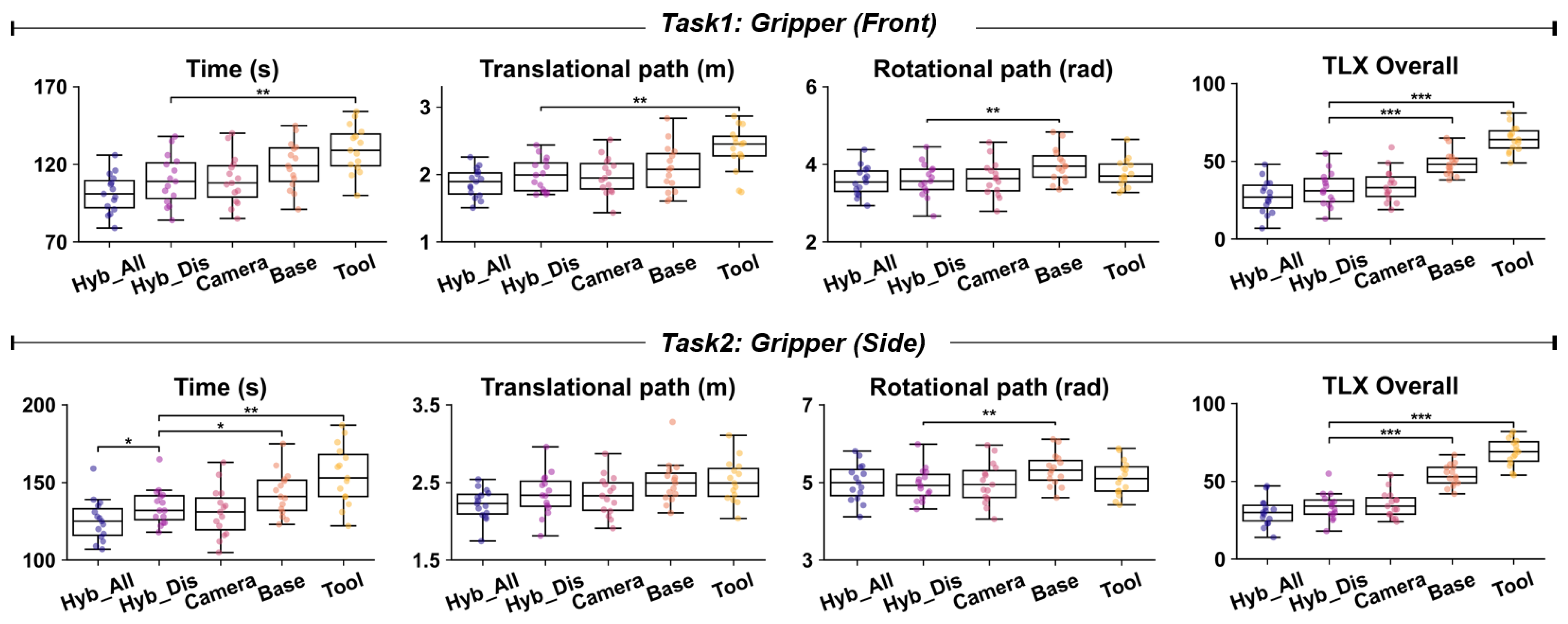
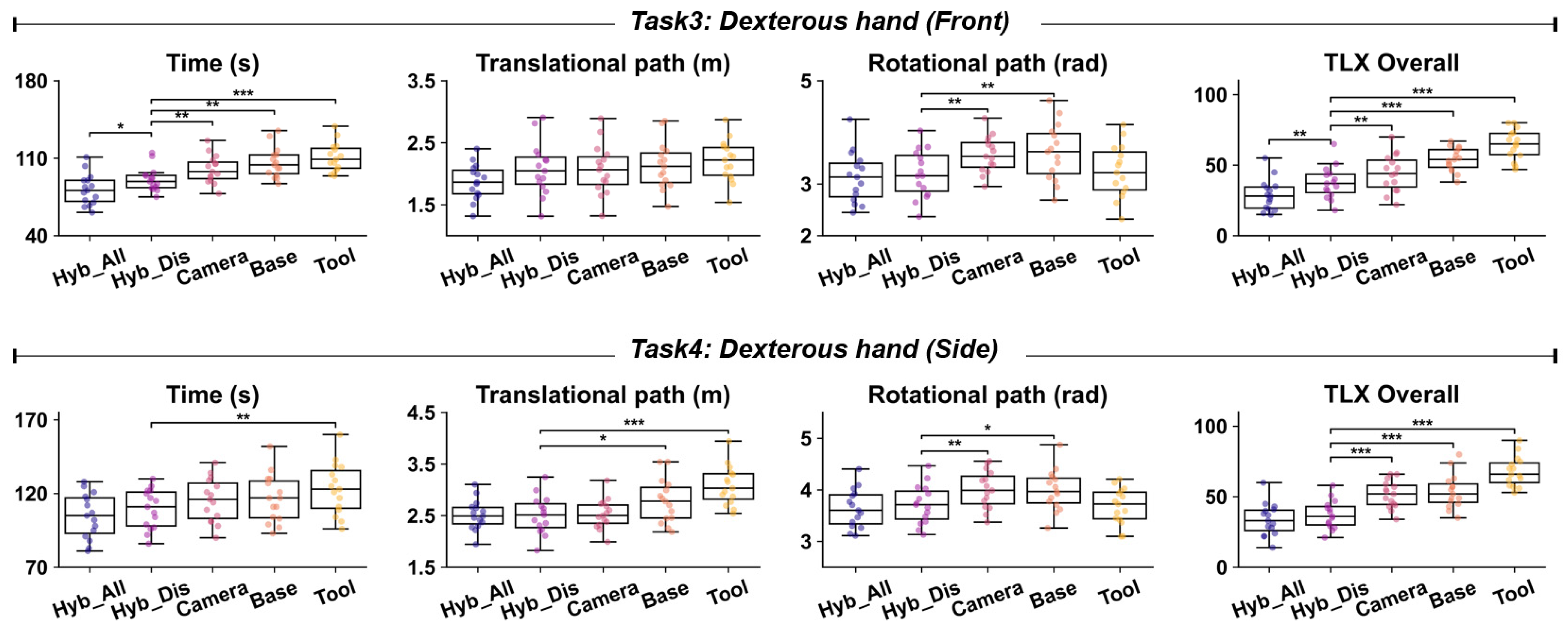
4.1. Evaluation of the Intuitiveness Advantage of the Hybrid Reference Frame (Hybrid_Discrete vs. Camera, Base, Tool)
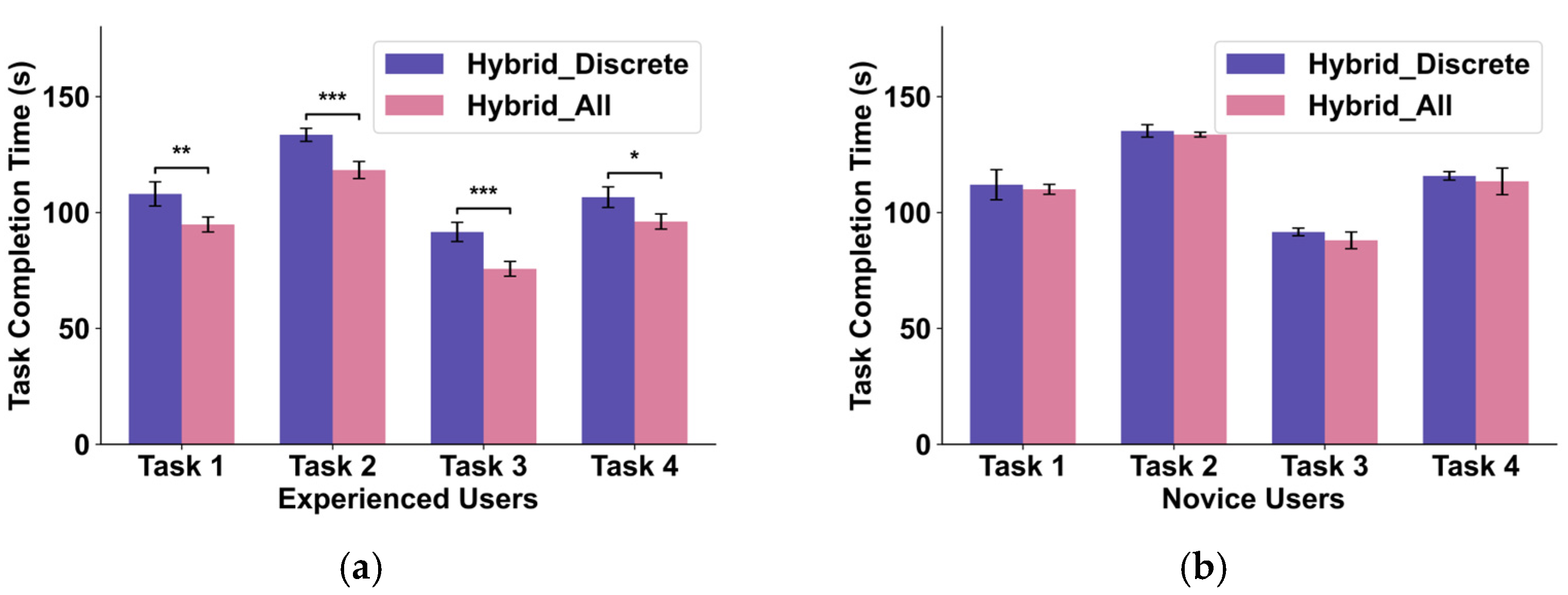
4.2. Evaluation of the Efficiency of FSM Control Logic (Hybrid_All vs. Hybrid_Discrete)
4.3. Analysis of the Impact of Camera Perspective and End-Effector Type
5. Discussion
5.1. Advantages of the Proposed Method
5.2. Limitations and Future Work
6. Conclusions
Supplementary Materials
Author Contributions
Funding
Institutional Review Board Statement
Informed Consent Statement
Data Availability Statement
Acknowledgments
Conflicts of Interest
References
- Sajwan, M.; Singh, S. A Review on the Effectiveness of Machine Learning and Deep Learning Algorithms for Collaborative Robot. Arch. Comput. Methods Eng. 2023, 30, 3489–3508. [Google Scholar] [CrossRef]
- Duan, J.; Zhuang, L.; Zhang, Q.; Zhou, Y.; Qin, J. Multimodal perception-fusion-control and human-robot collaboration in manufacturing: A review. Int. J. Adv. Manuf. Technol. 2024, 132, 1071–1093. [Google Scholar] [CrossRef]
- Borboni, A.; Reddy, K.V.V.; Elamvazuthi, I.; Al-Quraishi, M.S.; Natarajan, E.; Ali, S.S.A. The Expanding Role of Artificial Intelligence in Collaborative Robots for Industrial Applications: A Systematic Review of Recent Works. Machines 2023, 11, 111. [Google Scholar] [CrossRef]
- Yerebakan, M.O.; Hu, B. Human-Robot Collaboration in Modern Agriculture: A Review of the Current Research Landscape. Adv. Intell. Syst. 2024, 6, 2300823. [Google Scholar] [CrossRef]
- Rekha, D.; Kaliyappan, H.K. Collaborative robot acting as scrub nurse for cataract surgery (CRASCS). J. Robot. Surg. 2024, 18, 339. [Google Scholar] [CrossRef] [PubMed]
- Ribeiro, T.; Goncalves, F.; Garcia, I.S.; Lopes, G.; Ribeiro, A.F. CHARMIE: A Collaborative Healthcare and Home Service and Assistant Robot for Elderly Care. Appl. Sci. 2021, 11, 7248. [Google Scholar] [CrossRef]
- Li, C.; Tian, G.; Zhang, M. A semantic knowledge-based method for home service robot to grasp an object. Knowl.-Based Syst. 2024, 297, 111947. [Google Scholar] [CrossRef]
- Luo, S.; Wu, H.; Duan, S.; Lin, Y.; Rojas, J. Endowing Robots with Longer-term Autonomy by Recovering from External Disturbances in Manipulation Through Grounded Anomaly Classification and Recovery Policies. J. Intell. Robot. Syst. 2021, 101, 51. [Google Scholar] [CrossRef]
- Vats, S.; Likhachev, M.; Kroemer, O. Efficient Recovery Learning using Model Predictive Meta-Reasoning. arXiv 2023, arXiv:2209.13605. [Google Scholar] [CrossRef]
- Cordie, T.; Roberts, J.; Dunbabin, M.; Dungavell, R.; Bandyopadhyay, T. Enabling robustness to failure with modular field robots. Front. Robot. AI 2024, 11, 1225297. [Google Scholar] [CrossRef] [PubMed]
- Li, G.; Li, Q.; Yang, C.; Su, Y.; Yuan, Z.; Wu, X. The Classification and New Trends of Shared Control Strategies in Telerobotic Systems: A Survey. IEEE Trans. Haptics 2023, 16, 118–133. [Google Scholar] [CrossRef] [PubMed]
- Park, S.; Yoon, T.; Lee, J.; Park, S.; Choi, S. Quality-diversity based semi-autonomous teleoperation using reinforcement learning. Neural Netw. 2024, 179, 106543. [Google Scholar] [CrossRef] [PubMed]
- Selvaggio, M.; Cognetti, M.; Nikolaidis, S.; Ivaldi, S.; Siciliano, B. Autonomy in Physical Human-Robot Interaction: A Brief Survey. IEEE Robot. Autom. Lett. 2021, 6, 7989–7996. [Google Scholar] [CrossRef]
- Rea, D.J.; Seo, S.H. Still Not Solved: A Call for Renewed Focus on User-Centered Teleoperation Interfaces. Front. Robot. Ai 2022, 9, 704225. [Google Scholar] [CrossRef] [PubMed]
- Xu, H.; Xiong, A. Advances and Disturbances in sEMG-Based Intentions and Movements Recognition: A Review. IEEE Sens. J. 2021, 21, 13019–13028. [Google Scholar] [CrossRef]
- Wang, L.; Chen, Z.; Zhou, S.; Yu, Y.; Li, X. A Robust Myoelectric Gesture Recognition Method for Enhancing the Reliability of Human-Robot Interaction. IEEE Robot. Autom. Lett. 2025, 10, 3731–3738. [Google Scholar] [CrossRef]
- Schilling, M.; Ritter, H.J.; Ohl, F.W. Linking meta-learning to meta-structure. Behav. Brain Sci. 2024, 47, e164. [Google Scholar] [CrossRef] [PubMed]
- Ng, L.K.L.; Chow, S.S.M.; Assoc, U. GForce: GPU-Friendly Oblivious and Rapid Neural Network Inference. In Proceedings of the 30th USENIX Security Symposium, Electr Network, Virtual, 11–13 August 2021; pp. 2147–2164. [Google Scholar]
- Gariya, N.; Kumar, P.; Dobriyal, R. A review on soft robotic technologies. AIP Conf. Proc. 2023, 2521, 050004. [Google Scholar] [CrossRef]
- Handa, A.; Van Wyk, K.; Yang, W.; Liang, J.; Chao, Y.-W.; Wan, Q.; Birchfield, S.; Ratliff, N.; Fox, D. DexPilot: Vision-Based Teleoperation of Dexterous Robotic Hand-Arm System. In Proceedings of the IEEE International Conference on Robotics and Automation (ICRA), Electr Network, London, UK, 31 May–15 June 2020; pp. 9164–9170. [Google Scholar]
- Lv, H.; Kong, D.; Pang, G.; Wang, B.; Yu, Z.; Pang, Z.; Yang, G. GuLiM: A Hybrid Motion Mapping Technique for Teleoperation of Medical Assistive Robot in Combating the COVID-19 Pandemic. IEEE Trans. Med. Robot. Bionics 2022, 4, 106–117. [Google Scholar] [CrossRef] [PubMed]
- Xiong, D.; Zhang, D.; Chu, Y.; Zhao, Y.; Zhao, X. Intuitive Human-Robot-Environment Interaction with EMG Signals: A Review. IEEE-CAA J. Autom. Sin. 2024, 11, 1075–1091. [Google Scholar] [CrossRef]
- Zhu, B.; Zhang, D.; Chu, Y.; Gu, Y.; Zhao, X. SeNic: An Open Source Dataset for sEMG-Based Gesture Recognition in Non-Ideal Conditions. IEEE Trans. Neural Syst. Rehabil. Eng. 2022, 30, 1252–1260. [Google Scholar] [CrossRef] [PubMed]
- Wang, L.; Li, X.; Chen, Z.; Sun, Z.; Xue, J. Electrode Shift Fast Adaptive Correction for Improving Myoelectric Control Interface Performance. IEEE Sens. J. 2023, 23, 25036–25047. [Google Scholar] [CrossRef]
- Cruz, P.J.; Vasconez, J.P.; Romero, R.; Chico, A.; Benalcazar, M.E.; Alvarez, R.; Lopez, L.I.B.; Valdivieso Caraguay, A.L. A Deep Q-Network based hand gesture recognition system for control of robotic platforms. Sci. Rep. 2023, 13, 7956. [Google Scholar] [CrossRef] [PubMed]
- Shin, S.; Tafreshi, R.; Langari, R. EMG and IMU based real-time HCI using dynamic hand gestures for a multiple-DoF robot arm. J. Intell. Fuzzy Syst. 2018, 35, 861–876. [Google Scholar] [CrossRef]
- Kim, E.; Shin, J.; Kwon, Y.; Park, B. EMG-Based Dynamic Hand Gesture Recognition Using Edge AI for Human-Robot Interaction. Electronics 2023, 12, 1541. [Google Scholar] [CrossRef]
- Rakita, D.; Mutlu, B.; Gleicher, M.; Assoc Comp, M. An Autonomous Dynamic Camera Method for Effective Remote Teleoperation. In Proceedings of the 13th Annual ACM/IEEE International Conference on Human-Robot Interaction (HRI), Chicago, IL, USA, 5–8 March 2018; pp. 325–333. [Google Scholar]
- Wang, Y.; Praveena, P.; Gleicher, M. A Design Space of Control Coordinate Systems in Telemanipulation. IEEE Access 2024, 12, 64150–64164. [Google Scholar] [CrossRef]
- Campeau-Lecours, A.; Cote-Allard, U.; Dinh-Son, V.; Routhier, F.; Gosselin, B.; Gosselin, C. Intuitive Adaptive Orientation Control for Enhanced Human-Robot Interaction. IEEE Trans. Robot. 2019, 35, 509–520. [Google Scholar] [CrossRef]
- Wu, L.; Yu, F.; Thanh Nho, D.; Wang, J. Camera Frame Misalignment in a Teleoperated Eye-in-Hand Robot: Effects and a Simple Correction Method. IEEE Trans. Hum.-Mach. Syst. 2023, 53, 2–12. [Google Scholar] [CrossRef]
- DeJong, B.P.; Colgate, J.E.; Peshkin, M.A. Improving teleoperation: Reducing mental rotations and translations. In Proceedings of the IEEE International Conference on Robotics and Automation, New Orleans, LA, USA, 26 April–1 May 2004; pp. 3708–3714. [Google Scholar]
- Shao, S.; Zhou, Q.; Liu, Z. Mental workload characteristics of manipulator teleoperators with different spatial cognitive abilities. Int. J. Adv. Robot. Syst. 2019, 16, 1–10. [Google Scholar] [CrossRef]
- Menchaca-Brandan, M.A.; Liu, A.M.; Oman, C.M.; Natapoff, A. Influence of Perspective-Taking and Mental Rotation Abilities in Space Teleoperation; IEEE: Arlington, VA, USA, 2007; pp. 271–278. [Google Scholar]
- Chico, A.; Cruz, P.J.; Vasconez, J.P.; Benalcazar, M.E.; Alvarez, R.; Barona, L.; Valdivieso, A.L. Hand Gesture Recognition and Tracking Control for a Virtual UR5 Robot Manipulator; IEEE: Arlington, VA, USA, 2021. [Google Scholar] [CrossRef]
- Guo, Y.; Yao, P.; Gou, G.; Liu, C.; Liu, J.; Zhou, J.; Cheng, J.; Zhao, M.; Xue, N. sEMG-Based Wearable HMI System For Real-Time Robotic Arm Control With Edge AI; IEEE: Arlington, VA, USA, 2023; pp. 1–5. [Google Scholar] [CrossRef]
- Sheridan, T.B. Telerobotics, Automation, and Human Supervisory Control; MIT Press: Cambridge, MA, USA, 1992. [Google Scholar] [CrossRef]


| Measures | Hybrid_All Mean (SD) | Hybrid _Dis Mean (SD) | Camera Mean (SD) | Base Mean (SD) | Tool Mean (SD) | F(4, 70) | p | η2 |
|---|---|---|---|---|---|---|---|---|
| Task 1: Gripper (Front) | ||||||||
| Time (s) | 101.4 (12.6) | 110.1 (16.1) | 110.0 (15.8) | 119.5 (15.5) | 129.7 (15.2) | 7.67 | <0.001 | 0.31 |
| Translational path (m) | 1.87 (0.21) | 1.99 (0.25) | 1.98 (0.27) | 2.08 (0.35) | 2.37 (0.33) | 6.58 | <0.001 | 0.27 |
| Rotational path (rad) | 3.57 (0.38) | 3.60 (0.43) | 3.62 (0.46) | 3.98 (0.43) | 3.78 (0.36) | 2.51 | 0.051 | 0.13 |
| TLX Overall | 27.4 (10.9) | 32.6 (11.2) | 34.4 (10.6) | 48.7 (7.7) | 64.5 (8.5) | 35.22 | <0.001 | 0.67 |
| Task 2: Gripper (Side) | ||||||||
| Time (s) | 125.6 (13.6) | 134.7 (11.9) | 131.1 (15.9) | 142.9 (14.3) | 154.9 (19.1) | 8.51 | <0.001 | 0.33 |
| Translational path (m) | 2.22 (0.20) | 2.35 (0.28) | 2.33 (0.26) | 2.51 (0.28) | 2.52 (0.27) | 3.55 | 0.011 | 0.17 |
| Rotational path (rad) | 5.00 (0.48) | 4.96 (0.43) | 4.99 (0.54) | 5.33 (0.42) | 5.12 (0.46) | 1.64 | 0.173 | 0.12 |
| TLX Overall | 30.2 (8.9) | 34.0 (8.8) | 35.3 (8.4) | 53.9 (6.9) | 68.7 (8.7) | 57.38 | <0.001 | 0.77 |
| Task 3: Dexterous hand (Front) | ||||||||
| Time (s) | 81.8 (14.1) | 90.9 (10.9) | 100.1 (12.6) | 106.1 (13.8) | 110.9 (13.2) | 12.31 | <0.001 | 0.41 |
| Translational path (m) | 1.87 (0.29) | 2.08 (0.42) | 2.07 (0.41) | 2.14 (0.38) | 2.20 (0.34) | 1.71 | 0.157 | 0.11 |
| Rotational path (rad) | 3.13 (0.49) | 3.20 (0.46) | 3.57 (0.35) | 3.62 (0.55) | 3.25 (0.51) | 3.24 | 0.017 | 0.16 |
| TLX Overall | 28.8 (11.2) | 37.6 (11.6) | 44.3 (13.3) | 54.0 (8.3) | 64.7 (10.8) | 23.58 | <0.001 | 0.57 |
| Task 4: Dexterous hand (Side) | ||||||||
| Time (s) | 104.7 (15.2) | 109.5 (13.4) | 115.6 (14.8) | 116.5 (16.4) | 123.3 (17.6) | 3.13 | 0.021 | 0.15 |
| Translational path (m) | 2.52 (0.29) | 2.51 (0.37) | 2.53 (0.29) | 2.79 (0.43) | 3.09 (0.38) | 7.6 | <0.001 | 0.31 |
| Rotational path (rad) | 3.64 (0.38) | 3.72 (0.38) | 4.00 (0.37) | 3.99 (0.40) | 3.68 (0.35) | 3.34 | 0.015 | 0.16 |
| TLX Overall | 33.8 (11.5) | 37.3 (10.1) | 51.6 (9.6) | 53.8 (12.2) | 67.9 (10.6) | 24.15 | <0.001 | 0.58 |
Disclaimer/Publisher’s Note: The statements, opinions and data contained in all publications are solely those of the individual author(s) and contributor(s) and not of MDPI and/or the editor(s). MDPI and/or the editor(s) disclaim responsibility for any injury to people or property resulting from any ideas, methods, instructions or products referred to in the content. |
© 2025 by the authors. Licensee MDPI, Basel, Switzerland. This article is an open access article distributed under the terms and conditions of the Creative Commons Attribution (CC BY) license (https://creativecommons.org/licenses/by/4.0/).
Share and Cite
Wang, L.; Chen, Z.; Han, S.; Luo, Y.; Li, X.; Liu, Y. An Intuitive and Efficient Teleoperation Human–Robot Interface Based on a Wearable Myoelectric Armband. Biomimetics 2025, 10, 464. https://doi.org/10.3390/biomimetics10070464
Wang L, Chen Z, Han S, Luo Y, Li X, Liu Y. An Intuitive and Efficient Teleoperation Human–Robot Interface Based on a Wearable Myoelectric Armband. Biomimetics. 2025; 10(7):464. https://doi.org/10.3390/biomimetics10070464
Chicago/Turabian StyleWang, Long, Zhangyi Chen, Songyuan Han, Yao Luo, Xiaoling Li, and Yang Liu. 2025. "An Intuitive and Efficient Teleoperation Human–Robot Interface Based on a Wearable Myoelectric Armband" Biomimetics 10, no. 7: 464. https://doi.org/10.3390/biomimetics10070464
APA StyleWang, L., Chen, Z., Han, S., Luo, Y., Li, X., & Liu, Y. (2025). An Intuitive and Efficient Teleoperation Human–Robot Interface Based on a Wearable Myoelectric Armband. Biomimetics, 10(7), 464. https://doi.org/10.3390/biomimetics10070464