
Development of Magnetic Sponges Using Steel Melting on 3D Carbonized Spongin Scaffolds Under Extreme Biomimetics Conditions

 , ,
, ,  ,
,  , ,
, ,  ,
, 
Abstract

1. Introduction
- ⮚
- finding relevant renewable natural sources and examples of inspiration in nature;
- ⮚
- understanding biological principles and mechanisms underlying natural phenomena;
- ⮚
- applying of accessible procedures related to the use of biological materials;
- ⮚
2. Materials and Methods
2.1. Materials
2.2. Sample Preparation
- (a)
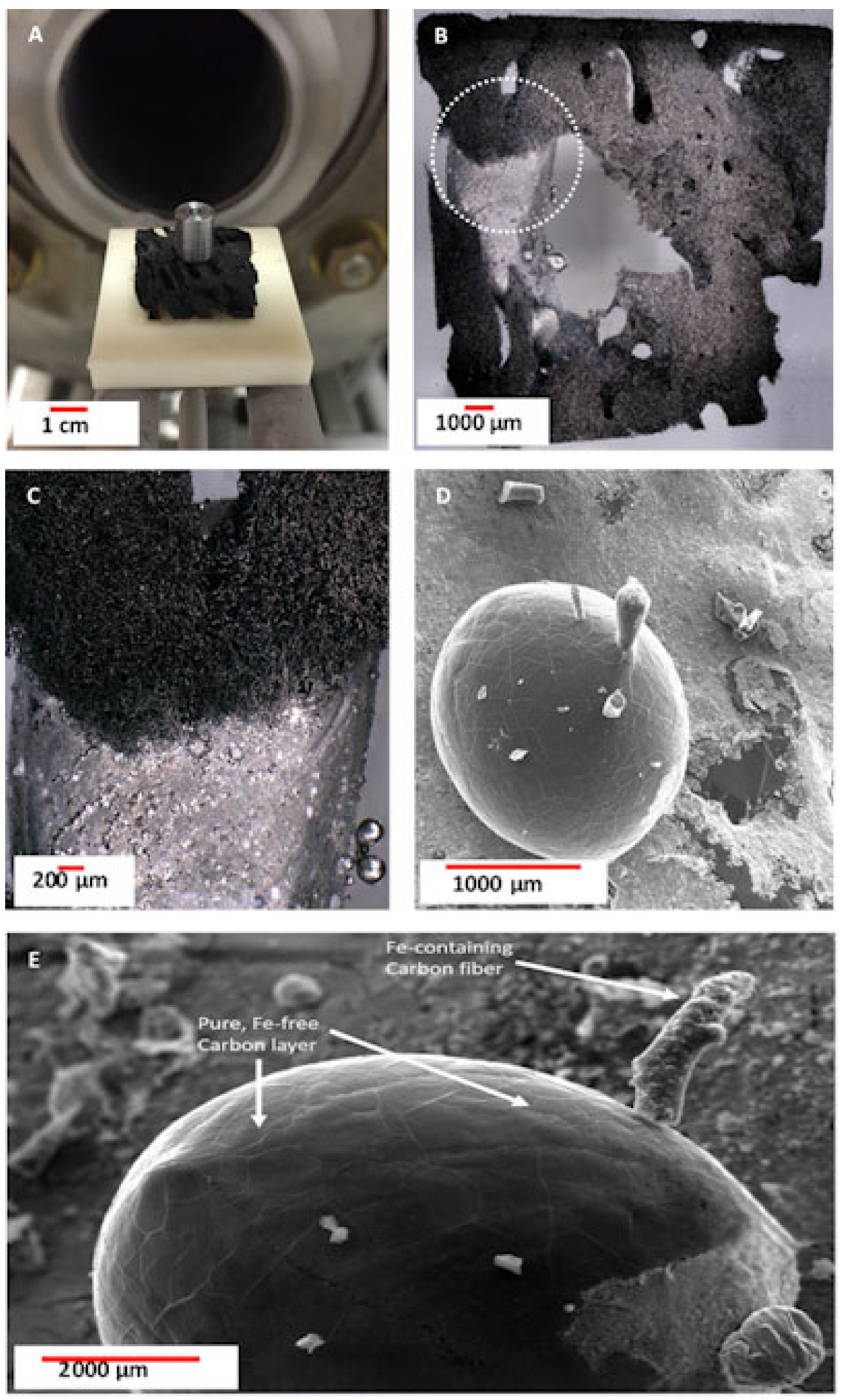
- construction steel EN S235JRG2 (AISI 1015), carbon steel C45, stainless steel 316 L powder, and No. 172/1 low alloy cast iron (see Supplementary Materials, Figure S1) were melted on carbonized spongin scaffolds, which were obtained from samples after HCl treatment using the high-temperature furnace during 90 min at 1450 °C under oxygen-free conditions.
2.3. Characterization Techniques
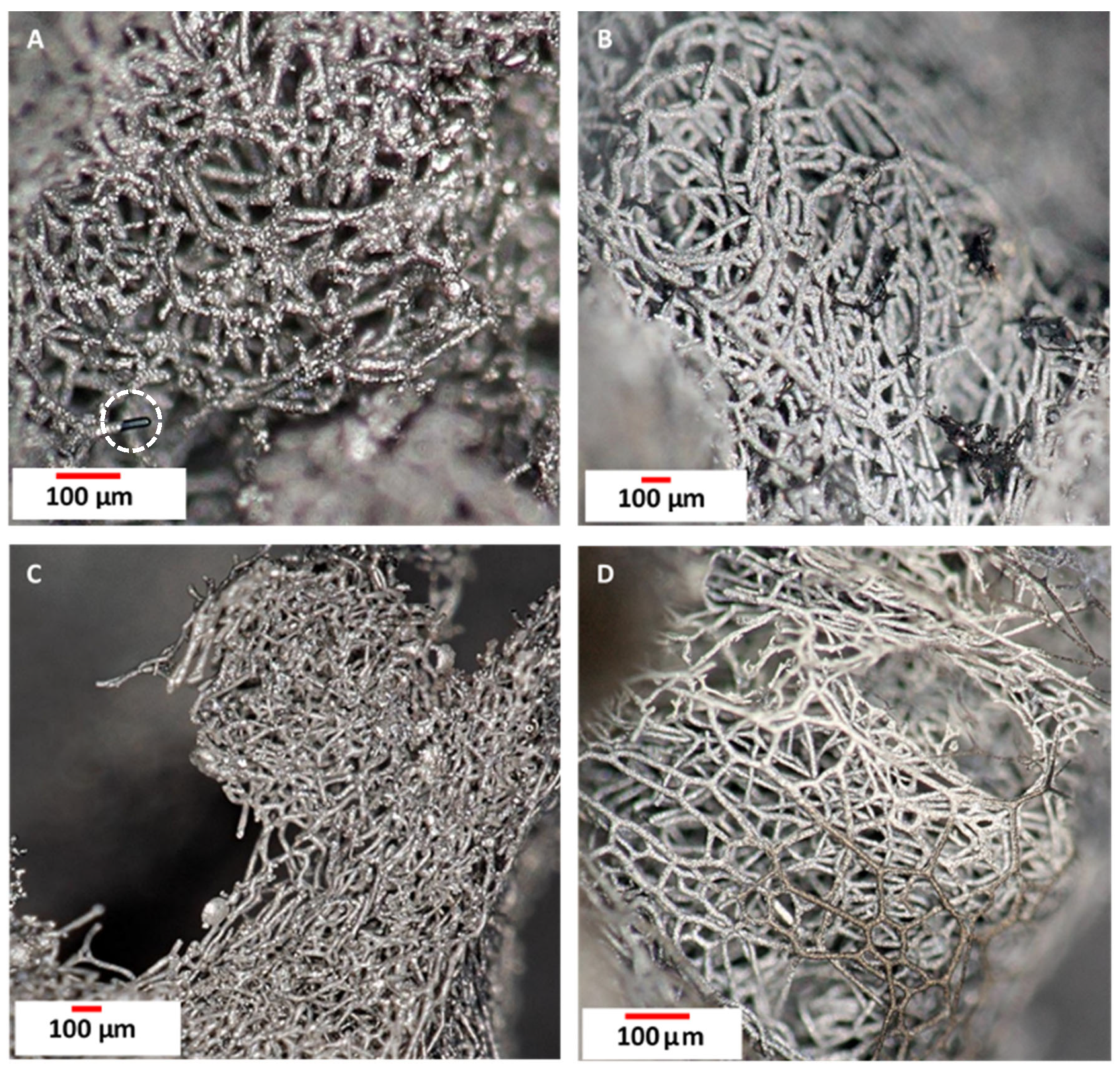
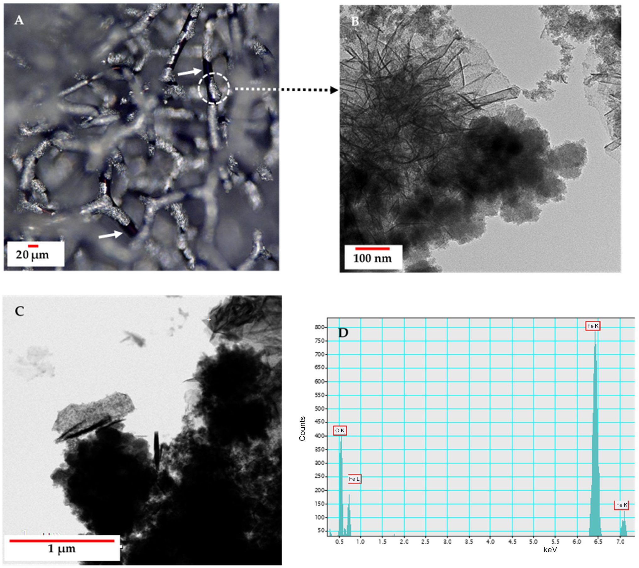
2.3.1. Digital Optical Microscopy
2.3.2. Scanning Electron Microscopy (SEM) with Energy Dispersive X-Ray Analysis (EDX)/Elemental Mapping
2.3.3. Fourier Transform Infrared Spectroscopy
2.3.4. X-Ray Diffraction
2.3.5. Magnetic Properties
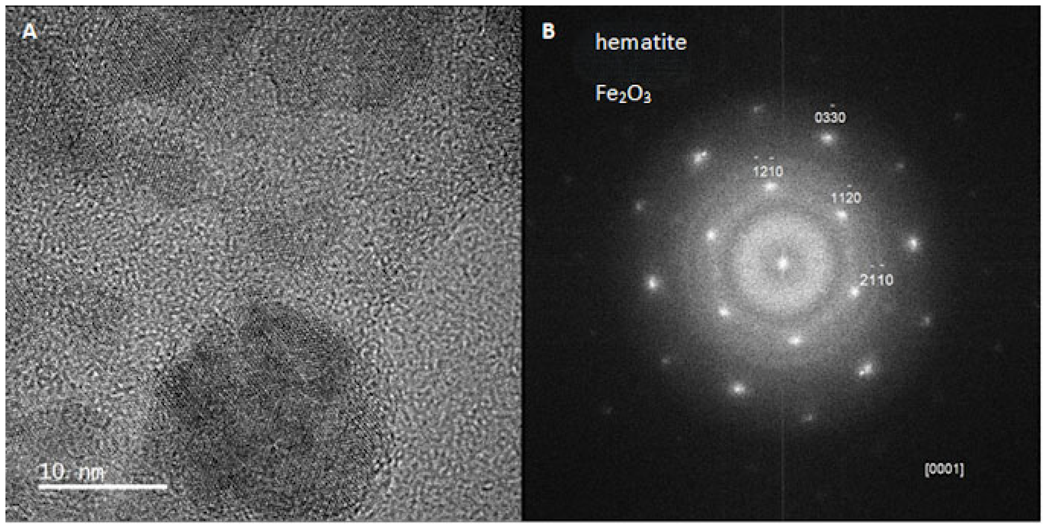
2.3.6. Transmission Electron Microscopy (TEM)
2.4. Electrochemical Measurements
2.4.1. Electrochemical Cell Configuration
2.4.2. Preparation of the Working Electrode
2.4.3. Electrochemical Measurements
3. Results
3.1. Digital Optical Microscopy
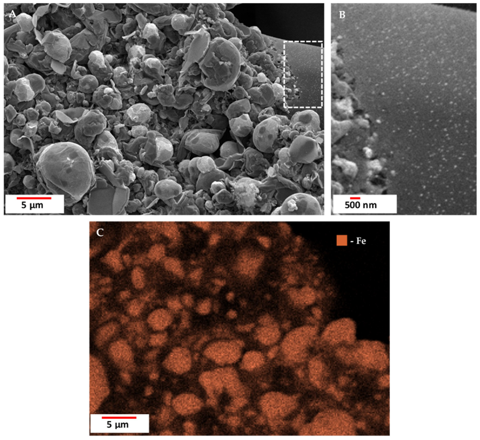
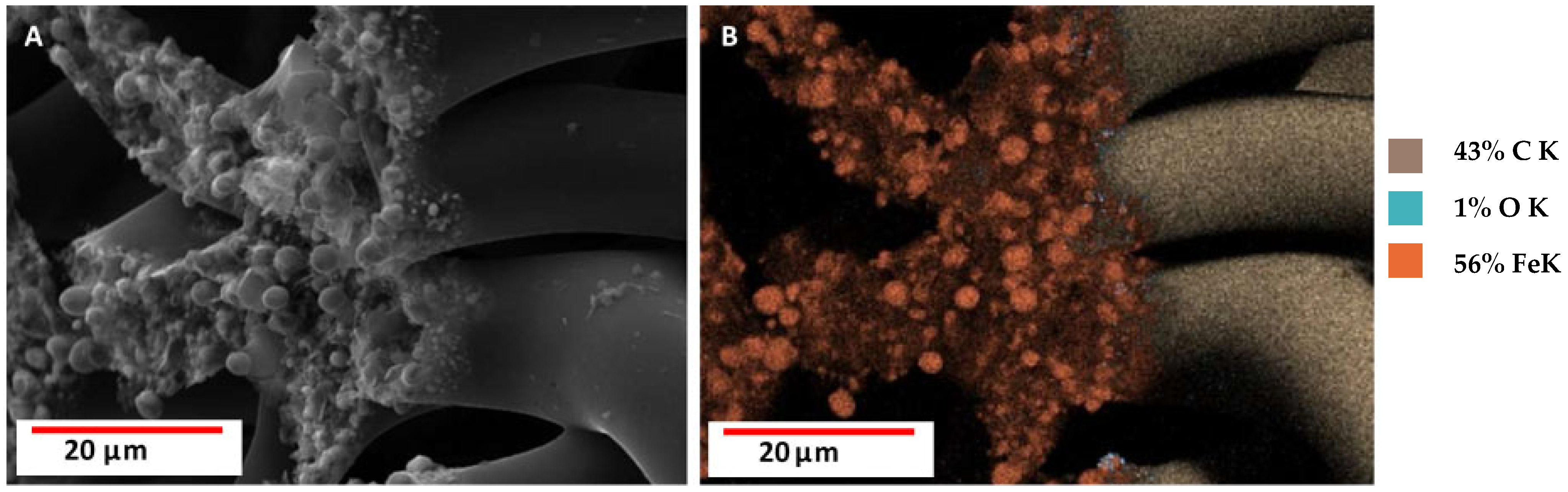
3.2. Scanning Electron Microscopy (SEM) with Energy Dispersive X-Ray Analysis (EDX)/Elemental Mapping
3.3. Fourier Transform Infrared Spectroscopy
3.4. X-Ray Diffraction
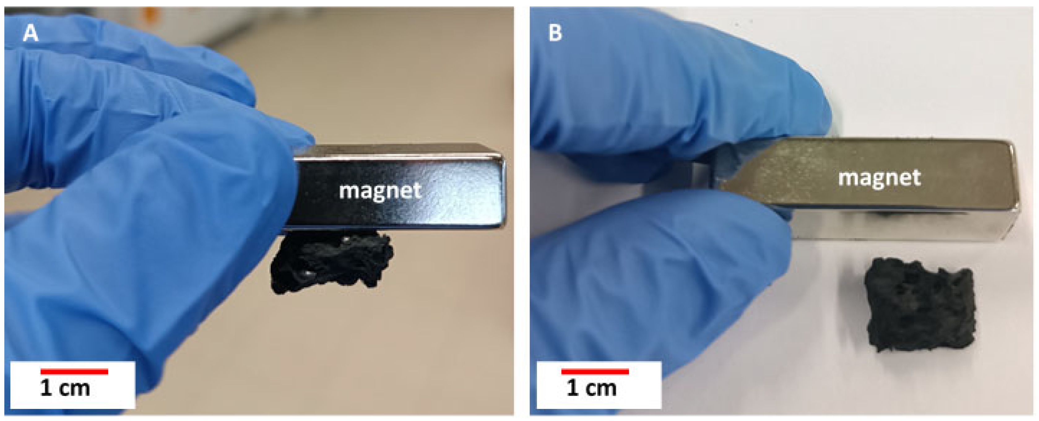
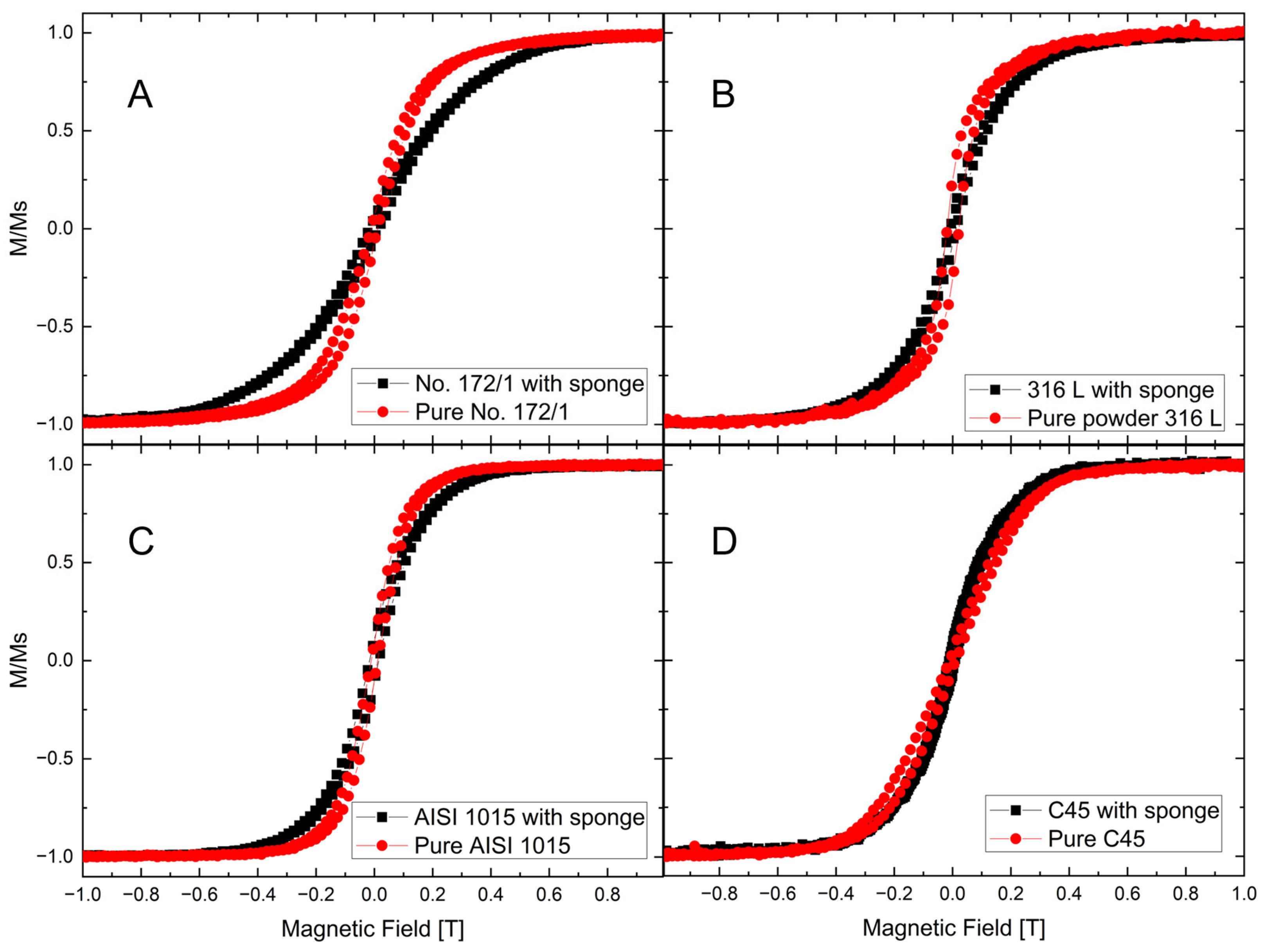
3.5. Magnetic Properties
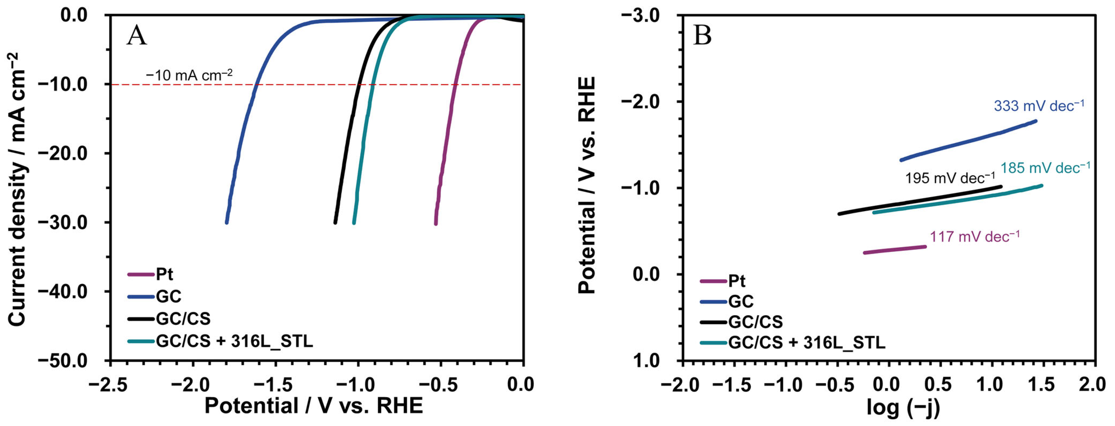
3.6. Catalytic Properties During the Hydrogen Evolution Reaction
4. Discussion
5. Conclusions
Supplementary Materials
Author Contributions
Funding
Institutional Review Board Statement
Informed Consent Statement
Data Availability Statement
Acknowledgments
Conflicts of Interest
References
- Szatkowski, T.; Siwínska-Stefańska, K.; Wysokowski, M.; Stelling, A.L.; Joseph, Y.; Ehrlich, H.; Jesionowski, T. Immobilization of titanium(IV) oxide onto 3D spongin scaffolds of marine sponge origin according to extreme biomimetics principles for removal of C.I. basic blue 9. Biomimetics 2017, 2, 4. [Google Scholar] [CrossRef] [PubMed]
- Gorb, S.N.; Carbone, G.; Speck, T.; Taubert, A. Advances in Biomimetics: Combination of Various Effects at Different Scales. Biomimetics 2023, 8, 329. [Google Scholar] [CrossRef] [PubMed]
- Kubiak, A.; Voronkina, A.; Pajewska-Szmyt, M.; Kotula, M.; Leśniewski, B.; Ereskovsky, A.; Heimler, K.; Rogoll, A.; Vogt, C.; Rahimi, P.; et al. Creation of a 3D Goethite–Spongin Composite Using an Extreme Biomimetics Approach. Biomimetics 2023, 8, 533. [Google Scholar] [CrossRef] [PubMed]
- Ehrlich, H.; Wysokowski, M.; Jesionowski, T. The philosophy of extreme biomimetics. Sustain. Mater. Technol. 2022, 32, e00447. [Google Scholar] [CrossRef]
- Wysokowski, M.; Motylenko, M.; Walter, J.; Lota, G.; Wojciechowski, J.; Stöcker, H.; Galli, R.; Stelling, A.L.; Himcinschi, C.; Niederschlag, E.; et al. Synthesis of nanostructured chitin-hematite composites under extreme biomimetic conditions. RSC Adv. 2014, 4, 61743–61752. [Google Scholar] [CrossRef]
- Ehrlich, H. (Ed.) Extreme Biomimetics; Springer Nature: Cham, Switzerland, 2017. [Google Scholar]
- Ehrlich, H.; Simon, P.; Motylenko, M.; Wysokowski, M.; Bazhenov, V.V.; Galli, R.; Stelling, A.L.; Stawski, D.; Ilan, M.; Stöcker, H.; et al. Extreme Biomimetics: Formation of zirconium dioxide nanophase using chitinous scaffolds under hydrothermal conditions. J. Mater. Chem. B 2013, 1, 5092–5099. [Google Scholar] [CrossRef]
- Wysokowski, M.; Motylenko, M.; Beyer, J.; Makarova, A.; Stöcker, H.; Walter, J.; Galli, R.; Kaiser, S.; Vyalikh, D.; Bazhenov, V.V.; et al. Extreme biomimetic approach for developing novel chitin-GeO2 nanocomposites with photoluminescent properties. Nano Res. 2015, 8, 2288–2301. [Google Scholar] [CrossRef]
- Ehrlich, H.; Miksik, I.; Tsurkan, M.V.; Simon, P.; Porzucek, F.; Rybka, J.D.; Mankowska, M.; Galli, R.; Viehweger, C.; Brendler, E.; et al. Discovery of mammalian collagens I and III within ancient poriferan biopolymer spongin. Nat. Commun. 2025, 16, 2515. [Google Scholar] [CrossRef]
- Leśniewski, B.; Kotula, M.; Kubiak, A.; Pajewska-Szmyt, M. Thermostability of Selected Biological Materials. Lett. Appl. NanoBioSci. 2023, 12, 7–9. [Google Scholar]
- Ehrlich, H.; Wysokowski, M.; Zółtowska-Aksamitowska, S.; Petrenko, I.; Jesionowski, T. Collagens of poriferan origin. Mar. Drugs 2018, 16, 79. [Google Scholar] [CrossRef]
- Żółtowska, S.; Koltsov, I.; Alejski, K.; Ehrlich, H.; Ciałkowski, M.; Jesionowski, T. Thermal decomposition behaviour and numerical fitting for the pyrolysis kinetics of 3D spongin-based scaffolds. The classic approach. Polym. Test. 2021, 97, 107148. [Google Scholar] [CrossRef]
- Jesionowski, T.; Norman, M.; Zółtowska-Aksamitowska, S.; Petrenko, I.; Joseph, Y.; Ehrlich, H. Marine spongin: Naturally prefabricated 3D scaffold-based biomaterial. Mar. Drugs 2018, 16, 88. [Google Scholar] [CrossRef] [PubMed]
- Kubiak, A.; Kotula, M.; Leśniewski, B.; Pajewska-Szmyt, M. Iron-sponges Interrelations: From Biocorrosion. Lett. Appl. NanoBioSci. 2022, 12, 64. [Google Scholar]
- Petrenko, I.; Summers, A.P.; Simon, P.; Zółtowska-Aksamitowska, S.; Motylenko, M.; Schimpf, C.; Rafaja, D.; Roth, F.; Kummer, K.; Brendler, E.; et al. Extreme biomimetics: Preservation of molecular detail in centimeter-scale samples of biological meshes laid down by sponges. Sci. Adv. 2019, 5, eaax2805. [Google Scholar] [CrossRef]
- Ehrlich, H. Marine Biological Materials of Invertebrate Origin; Gorb, S.N., Ed.; Springer Nature: Cham, Switzerland, 2019; Volume 13. [Google Scholar]
- Żółtowska, S.; Modelska, M.; Piasecki, A.; Jesionowski, T. Commercial sponges in heterogeneous catalysis: Developing novel composites with cobalt and silver. Physicochem. Probl. Miner. Process. 2020, 56, 89–100. [Google Scholar] [CrossRef]
- Kotula, M.; Kubiak, A.; Leśniewski, B.; Pajewska-Szmyt, M. Carbonization of Selected Biological Materials, Trends, and Perspectives. Lett. Appl. NanoBioSci. 2023, 12, 68. [Google Scholar]
- Szatkowski, T.; Kopczyński, K.; Motylenko, M.; Borrmann, H.; Mania, B.; Graś, M.; Lota, G.; Bazhenov, V.V.; Rafaja, D.; Roth, F.; et al. Extreme biomimetics: A carbonized 3D spongin scaffold as a novel support for nanostructured manganese oxide(IV) and its electrochemical applications. Nano Res. 2018, 11, 4199–4214. [Google Scholar] [CrossRef]
- Akbari, M.; Jafari, H.; Rostami, M.; Mahdavinia, G.R.; Nasab, A.S.; Tsurkan, D.; Petrenko, I.; Ganjali, M.R.; Rahimi-Nasrabadi, M.; Ehrlich, H. Adsorption of cationic dyes on a magnetic 3D spongin scaffold with nano-sized Fe3O4 cores. Mar. Drugs 2021, 19, 512. [Google Scholar] [CrossRef]
- Ehrlich, H.; Bailey, E.; Wysokowski, M.; Jesionowski, T. Forced biomineralization: A review. Biomimetics 2021, 6, 46. [Google Scholar] [CrossRef]
- Towe, K.M.; Rützler, K. Lepidocrocite iron mineralization in keratose sponge granules. Science 1968, 162, 268–269. [Google Scholar] [CrossRef]
- Vacelet, J.; Verdenal, B.; Perinet, G. The iron mineralization of Spongia officinalis L. (Porifera, Dictyoceratida) and its relationships with the collagen skeleton. Biol. Cell 1988, 62, 189–198. [Google Scholar] [CrossRef]
- Vlasov, A.Y.; Gornushkina, N.A.; Petrov, M.I. Crystal structure and magnetic properties of lepidocrocite upon thermal transformation to hematite. Sov. Phys. J. 1972, 15, 698–702. [Google Scholar] [CrossRef]
- Kubiak, A.; Pajewska-Szmyt, M.; Kotula, M.; Leśniewski, B.; Voronkina, A.; Rahimi, P.; Falahi, S.; Heimler, K.; Rogoll, A.; Vogt, C.; et al. Spongin as a Unique 3D Template for the Development of Functional Iron-Based Composites Using Biomimetic Approach In Vitro. Mar. Drugs 2023, 21, 460. [Google Scholar] [CrossRef] [PubMed]
- Nowacki, K.; Kubiak, A.; Nowicki, M.; Tsurkan, D.; Ehrlich, H.; Jesionowski, T. 3D Spongin Scaffolds as Templates for Electro-Assisted Deposition of Selected Iron Oxides. Biomimetics 2024, 9, 387. [Google Scholar] [CrossRef] [PubMed]
- Giannelli, M.; Barbalinardo, M.; Riminucci, A.; Belvedere, K.; Boccalon, E.; Sotgiu, G.; Corticelli, F.; Ruani, G.; Zamboni, R.; Aluigi, A.; et al. Magnetic keratin/hydrotalcites sponges as potential scaffolds for tissue regeneration. Appl. Clay Sci. 2021, 207, 106090. [Google Scholar] [CrossRef]
- Ma, W.; Wang, H. Magnetically driven motile superhydrophobic sponges for efficient oil removal. Appl. Mater. Today 2019, 15, 263–266. [Google Scholar] [CrossRef]
- Jiang, P.; Li, K.; Chen, X.; Dan, R.; Yu, Y. Magnetic and hydrophobic composite polyurethane sponge for oil-water separation. Appl. Sci. 2020, 10, 1453. [Google Scholar] [CrossRef]
- Lin, K.Y.A.; Chang, H.A.; Chen, B.J. Multi-functional MOF-derived magnetic carbon sponge. J. Mater. Chem. A 2016, 4, 13611–13625. [Google Scholar]
- Liu, H.; Su, S.; Xie, J.; Ma, Y.; Tao, C. Preparation of superhydrophobic magnetic stearic acid polyurethane sponge for oil-water separation. J. Mater. Res. 2020, 35, 2925–2935. [Google Scholar] [CrossRef]
- Lei, L.; Jia-qi, H.; Na, L. Preparation and oil absorption properties of magnetic melamine sponge. In Proceedings of the IOP Conference Series: Earth and Environmental Science 1st International Global on Renewable Energy and Development, Singapore, 22–25 December 2017; p. 012068. [Google Scholar]
- Li, L.; Li, B.; Wu, L.; Zhao, X.; Zhang, J. Magnetic, superhydrophobic and durable silicone sponges and their applications in removal of organic pollutants from water. Chem. Commun. 2014, 50, 7831–7833. [Google Scholar] [CrossRef]
- Falahi, S.; Kubiak, A.; Voronkina, A.; Ehrlich, H.; Joseph, Y.; Rahimi, P. Simultaneous Electrochemical Detection of Dopamine and Tryptophan Using 3D Goethite–Spongin Composites. Biomimetics 2024, 9, 357. [Google Scholar] [CrossRef]
- Linderhof, F.; Mashlan, M.; Doláková, H.; Ingr, T.; Ivanova, T. Surface micromorphology and structure of stainless and maraging steel obtained via selective laser melting: A mössbauer spectroscopy study. Metals 2021, 11, 1028. [Google Scholar] [CrossRef]
- Sharma, G.; Jeevanandam, P. Synthesis of self-assembled prismatic iron oxide nanoparticles by a novel thermal decomposition route. RSC Adv. 2013, 3, 189–200. [Google Scholar] [CrossRef]
- Namduri, H.; Nasrazadani, S. Quantitative analysis of iron oxides using Fourier transform infrared spectrophotometry. Corros. Sci. 2008, 50, 2493–2497. [Google Scholar] [CrossRef]
- Wang, Y.; Muramatsu, A.; Sugimoto, T. FTIR analysis of well-defined α-Fe2O3 particles. Colloids Surf. A Physicochem. Eng. Asp. 1998, 134, 281–297. [Google Scholar] [CrossRef]
- Yang, Z.; Han, Y.; Teng, Q.; Zhang, G.; Liu, S. Aggregation process of fine hematite particles suspension using xanthan gum in the presence of Fe(III). Arab. J. Chem. 2023, 16, 104539. [Google Scholar] [CrossRef]
- Castro, C.S.; Guerreiro, M.C.; Gonçalves, M.; Oliveira, L.C.A.; Anastácio, A.S. Activated carbon/iron oxide composites for the removal of atrazine from aqueous medium. J. Hazard. Mater. 2009, 164, 609–614. [Google Scholar] [CrossRef]
- Moore, C.; Perova, T.S.; Kennedy, B.J.; Berwick, K.; Shaganov, I.I.; Moore, R.A. Study of structure and quality of different silicon oxides using FTIR and Raman microscopy. In Opto-Ireland 2002: Optics and Photonics Technologies and Applications; SPIE: Bellingham, WA, USA, 2003; Volume 4876, pp. 1247–1256. [Google Scholar]
- Tran, T.N.; Pham, T.V.A.; Le, M.L.P.; Nguyen, T.P.T.; Tran, V.M. Synthesis of amorphous silica and sulfonic acid functionalized silica used as reinforced phase for polymer electrolyte membrane. Adv. Nat. Sci. Nanosci. Nanotechnol. 2013, 4, 045007. [Google Scholar] [CrossRef]
- Orbuleţ, O.D.; Borda, C.; Garleanu, D.; Garleanu, G.; Stancu, A.; Modrogan, C. Fe3O4 particles functionalized with edta and pva-preparation, characterization and their use in removal of manganese ions from synthetic aqueous solutions. UPB Sci. Bull. Ser. B Chem. Mater. Sci. 2021, 83, 101–116. [Google Scholar]
- Joni, I.M.; Nulhakim, L.; Vanitha, M.; Panatarani, C. Characteristics of crystalline silica (SiO2) particles prepared by simple solution method using sodium silicate (Na2SiO3) precursor. In IOP Conference Series: Journal of Physics: Conference Series, Proceedings of the 3rd Padjadjaran International Physics Symposium, Bandung, Indonesia, 14–15 November 2017; IOP Publishing: Philadelphia, PA, USA, 2018; Volume 1080, p. 12006. [Google Scholar]
- Hirano, Y.; Kasai, Y.; Sagata, K.; Kita, Y. Unique approach for transforming glucose to C3 platform chemicals using metallic iron and a Pd/C catalyst in water. Bull. Chem. Soc. Jpn. 2016, 89, 1026–1033. [Google Scholar] [CrossRef]
- Guo, L.; Ren, X.; Zhou, Y.; Xu, S.; Gong, Y.; Zhang, S. Theoretical evaluation of the corrosion inhibition performance of 1,3-thiazole and its amino derivatives. Arab. J. Chem. 2017, 10, 121–130. [Google Scholar] [CrossRef]
- Murugesan, S.; Kuznetsov, O.; Zhou, Z.; Khabashesku, V. Fluorescent Superparamagnetic Core-Shell Nanostructures: Facile Synthesis of Fe@C-CNx Particles for Reusable Photocatalysts. Adv. Nanopart. 2019, 8, 1. [Google Scholar] [CrossRef]
- Wahab, R.; Khan, F.; Al-Khedhairy, A.A. Hematite iron oxide nanoparticles: Apoptosis of myoblast cancer cells and their arithmetical assessment. RSC Adv. 2018, 8, 24750–24759. [Google Scholar] [CrossRef]
- Joseph, A.; Praveena, M.; Subair, T.; Al-Omari, I.; Anantharamaniyer, M.R. A simple polyol one-shot synthesis of Maghemite and Hematite from inexpensive precursors. Inorg. Chem. Commun. 2023, 151, 110590. [Google Scholar]
- Zainuri, M. Hematite from Natural Iron Stones as Microwave Absorbing Material on X-Band Frequency Ranges. In IOP Conference Series: Materials Science and Engineering, Proceedings of the 3rd International Conference on Functional Materials Science, Bali, Indonesia, 19–20 October 2016; IOP Publishing: Philadelphia, PA, USA, 2017; Volume 196, p. 012008. [Google Scholar]
- Salamun, N.; Ni, H.X.; Triwahyono, S.; Jalil, A.A.; Karim, A.H. Synthesis and characterization of Fe3O4 nanoparticles by electrodeposition and reduction methods. J. Fundam. Sci. 2011, 7, 89–92. [Google Scholar] [CrossRef]
- Bertolucci, E.; Galletti, A.M.R.; Antonetti, C.; Marracci, M.; Tellini, B.; Piccinelli, F.; Visone, C. Chemical and magnetic properties characterization of magnetic nanoparticles. In Proceedings of the IEEE Instrumentation and Measurement Technology Conference, Pisa, Italy, 11–14 May 2015; pp. 1492–1496. [Google Scholar]
- Sui, Y.; Lu, F.; Liu, X.; Zhang, Y.; Sun, X.; Liu, C. Enhance room-temperature ferromagnetism of α-Fe2O3 nanomaterials by easy and scalable method. Phys. Lett. Sect. A Gen. At. Solid State Phys. 2021, 408, 127488. [Google Scholar] [CrossRef]
- Debnath, A.; Bhattacharya, S.; Mondal, T.K.; Tada, H.; Saha, S.K. Giant enhancement in coercivity of ferromagnetic α-Fe2O3 nanosheet grown on MoS2. J. Appl. Phys. 2020, 127, 013901. [Google Scholar] [CrossRef]
- Craig, D.J. (Ed.) Magnetic Oxides; Wiley & Sons Ltd.: London, UK, 1975. [Google Scholar]
- Borresen, B.; Hagen, G.; Tunold, R. Hydrogen evolution on RuxTi1-xO2 in 0.5 M H2SO4. Electrochim. Acta 2002, 47, 1819–1827. [Google Scholar] [CrossRef]
- Mahmood, N.; Yao, Y.; Zhang, J.W.; Pan, L.; Zhang, X.; Zou, J.J. Electrocatalysts for Hydrogen Evolution in Alkaline Electrolytes: Mechanisms, Challenges, and Prospective Solutions. Adv. Sci. 2018, 5, 1700464. [Google Scholar] [CrossRef]
- Anjana, R.; Hanamantrao, D.P.; Nasrin Banu, G.; Raja, V.; Isaac, R.S.R.; John, J.S.; Vediappan, K.; Jose, S.P.; Neppolian, B.; Sajan, D. Hydrothermal synthesis of graphitic carbon nitride/Ce doped Fe2O3 heterostructures for supercapattery device and hydrogen evolution reaction. J. Energy Storage 2025, 116, 116021. [Google Scholar] [CrossRef]
- Tong, H.; Zheng, X.; Qi, M.; Li, D.; Zhu, J.; Jiang, D. Synergistically coupled CoMo/Fe2O3 electrocatalyst for highly efficient and stable overall water splitting. J. Colloid Interface Sci. 2024, 676, 837–846. [Google Scholar] [CrossRef] [PubMed]
- Shetti, R.S.; Sreenivasulu, M.; Maiyalagan, T.; Alibrahim, K.A.; Alodhayb, A.N.; Shetti, N.P. Enhanced electrocatalytic performance of in situ pyrolized iron oxide-embedded carbon composite for sustainable hydrogen production. Diam. Relat. Mater. 2025, 155, 112305. [Google Scholar] [CrossRef]
- Li, L.; Wang, K.; Lei, T. Petal-like NiFe2O4/Fe2O3 heterostructure nanoarrays as bifunctional electrocatalyst for highly efficient alkaline overall water splitting. Inorg. Chem. Commun. 2025, 173, 113801. [Google Scholar] [CrossRef]
- Saadh, M.J.; Jasim, D.J.; Alejandro, L.; Saraswat, S.K.; Arévalo, C.G.F.; Brito, N.A.E.; Zainul, R.; Hasan, M.A.; Islam, S. Harnessing the potential of MOF/Fe2O3 nanocomposite within polypyrrole matrix for enhanced hydrogen evolution. Electrochim. Acta 2024, 507, 145157. [Google Scholar] [CrossRef]
- Li, X.; Yang, Z.; Zhao, X.; Gao, M.; Liu, Y. Bio-derived mesoporous carbon confinement synthesis of ultra-small α-Fe2O3 nanoparticles as electrocatalysts for overall water splitting. J. Electroanal. Chem. 2024, 973, 118644. [Google Scholar] [CrossRef]
- Ibarra, J.; Aguirre, M.J.; del Río, R.; Henriquez, R.; Faccio, R.; Dalchiele, E.A.; Arce, R.; Ramírez, G. α-Fe2O3/, Co3O4/, and CoFe2O4/MWCNTs/Ionic Liquid Nanocomposites as High-Performance Electrocatalysts for the Electrocatalytic Hydrogen Evolution Reaction in a Neutral Medium. Int. J. Mol. Sci. 2024, 25, 7043. [Google Scholar] [CrossRef]
- Wang, B.; Chen, X.; He, Y.; Liu, Q.; Zhang, X.; Luo, Z.; Kennedy, J.V.; Li, J.; Qian, D.; Liu, J.; et al. Fe2O3/P-doped CoMoO4 electrocatalyst delivers efficient overall water splitting in alkaline media. Appl. Catal. B Environ. 2024, 346, 123741. [Google Scholar] [CrossRef]
- Li, L.; He, C.; Lei, W.; Gao, P.; Lei, T. In situ synthesis of Fe2O3/Fe3O4 nanoarray hybrid as highly effective electrocatalysts for alkaline hydrogen evolution. J. Alloys Compd. 2024, 978, 173501. [Google Scholar] [CrossRef]
- Kroll, J.W. Melting and evaporating metals in a vacuum. Trans. Elecrochem. Soc. 1945, 87, 571–587. [Google Scholar] [CrossRef]
- Ono, K.; Suzuki, R.O. Evaporation Processes in Vacuum Metallurgy. J. Mass Spectrom. Soc. Jpn. 1999, 47, 38–41. [Google Scholar] [CrossRef]
- Poullain, T.; Bellot, J.P.; Jourdan, J.; Crassous, I.; Jardy, A. Vacuum evaporation and expansion of pure metals at high temperature: Application to titanium and zirconium. Vacuum 2022, 203, 111209. [Google Scholar] [CrossRef]
- Khalimova, G.; Levchenko, M.; Markus, H.P.; Sosin, D.; Kreschel, T.; Volkova, O. Cu Evaporation from Liquid Iron Alloy in Stream. Metals 2024, 14, 1233. [Google Scholar] [CrossRef]
- Nawer, J.; Stanford, B.; Kolbe, M.; Schneider, S.; Gossé, S.; Wunderlich, R.K.; Mohr, M.; Borzì, A.; Neels, A.; Matson, D.M. Thermodynamic assessment of evaporation during molten steel testing onboard the International Space Station. npj Microgravity 2024, 10, 77. [Google Scholar] [CrossRef] [PubMed]
- Fayazi, M.; Liu, B.; Lei, L.; Shuai, G.; Odunmbaku, O.; Wang, S.; He, Y.; Boi, F.S. Ferromagnetic hysteresis and structural recrystallization in turbostratic graphite. Mater. Res. Express 2019, 6, 105612. [Google Scholar] [CrossRef]
- Höhne, R.; Esquinazi, P.; Heera, V.; Weishart, H.; Setzer, A.; Spemann, D. The influence of iron, fluorine and boron implantation on the magnetic properties of graphite. J. Magn. Magn. Mater. 2008, 320, 966–977. [Google Scholar] [CrossRef]
- Červenka, J.; Katsnelson, M.I.; Flipse, C.F.J. Room-temperature ferromagnetism in graphite driven by two-dimensional networks of pointdefects. Nat. Phys. 2009, 5, 840–844. [Google Scholar] [CrossRef]
- De Alwis, C.; Leftwich, T.R.; Mukherjee, P.; Denofre, A.; Perrine, K.A. Spontaneous selective deposition of iron oxide nanoparticles on graphite as model catalysts. Nanoscale Adv. 2019, 1, 4729–4744. [Google Scholar] [CrossRef]
- Yajun, Y.I.N.; Wen, L.I.; Shen, H.; Zhou, J.; Nan, H.; Deng, M.; Shen, X.; Zhixin, T.U. Molecular dynamics simulations of iron/graphite interfacial behaviors: Influence of oxygen. ISIJ Int. 2018, 58, 1022–1027. [Google Scholar]
- Koon, N.C.; Pehrsson, P.; Weber, D.; Schindler, A.I. Magnetic properties of iron-implanted graphite. J. Appl. Phys. 1984, 55, 2497–2499. [Google Scholar] [CrossRef]
- Vol’pin, M.E.; Novikov, Y.N. Coordination Chemistry of Graphite. Pure Appl. Chem. 1988, 60, 1133–1140. [Google Scholar] [CrossRef]
- Morishige, K.; Hamada, T. Iron oxide pillared graphite. Langmuir 2005, 21, 6277–6281. [Google Scholar] [CrossRef] [PubMed]
- Owen, R.E.; Cortezon-Tamarit, F.; Calatayud, D.G.; Evans, E.A.; Mitchell, S.I.J.; Mao, B.; Palomares, F.J.; Mitchels, J.; Plucinski, P.; Mattia, D.; et al. Shedding Light Onto the Nature of Iron Decorated Graphene and Graphite Oxide Nanohybrids for CO2 Conversion at Atmospheric Pressure. ChemistryOpen 2020, 9, 242–252. [Google Scholar] [CrossRef] [PubMed]
- Boukhvalov, D.W. First-principles modeling of the interactions of iron impurities with graphene and graphite. Phys. Status Solidi (b) 2011, 248, 1347–1351. [Google Scholar] [CrossRef]
- Do, Q.C.; Moon, C.; Ko, S.; Kang, S.; Jang, A.; Kim, D.H. Hydrothermal decoration of iron oxide nanoparticles on expanded graphite for adsorptional of phosphorus. In Proceedings of the IEEE-NANO 2015—15th International Conference on Nanotechnology, Rome, Italy, 27–30 July 2015; pp. 258–261. [Google Scholar]
- Hunter, R.D.; Ramírez-Rico, J.; Schnepp, Z. Iron-catalyzed graphitization for the synthesis of nanostructured graphitic carbons. J. Mater. Chem. A 2022, 10, 4489–4516. [Google Scholar] [CrossRef]
- Thambiliyagodage, C.; Nakandala, S.; Siriwardana, B.; Lansakara, B. One pot synthesis of α-Fe2O3/turbostratic carbon composites and their photocatalytic activity under sunlight. Carbon Trends 2021, 5, 100130. [Google Scholar] [CrossRef]
- Ağaoğulları, D.; Madsen, S.J.; Ögüt, B.; Koh, A.L.; Sinclair, R. Synthesis and characterization of graphite-encapsulated iron nanoparticles from ball milling-assisted low-pressure chemical vapor deposition. Carbon 2017, 124, 170–179. [Google Scholar] [CrossRef]
- Gomez-Martin, A.; Schnepp, Z.; Ramirez-Rico, J. Structural Evolution in Iron-Catalyzed Graphitization of Hard Carbons. Chem. Mater. 2021, 33, 3087–3097. [Google Scholar] [CrossRef]
- Andris, A.; Fischer, F.; Herrmann, M.; Lippmann, W.; Hurtado, A. Investigations of Graphite Particle Interaction with Metallic Surfaces. Metals 2020, 10, 140. [Google Scholar] [CrossRef]
- Stoneham, A.M. The motions of iron particles on graphite. Appl. Surf. Sci. 1979, 3, 161–167. [Google Scholar] [CrossRef]
- Luo, Z.; Han, F.; Zhang, P.; Zhao, Y.; Huang, S.; Guan, Q.; Li, W. The construction of iron-based catalysts encapsulated by graphite for CO2 hydrogenation to light olefins. Chem. Eng. J. 2024, 490, 151674. [Google Scholar] [CrossRef]
- Nizhenko, V.I.; Floka, L.I. Contact reaction of graphite with liquid iron and iron base melts. Sov. Powder Metall. Met. Ceram. 1974, 13, 487–492. [Google Scholar] [CrossRef]
- Nikonova, R.M.; Lad’Yanov, V.V. Contact interaction of metal melts with fullerite and graphite. J. Mater. Res. Technol. 2020, 9, 12559–12567. [Google Scholar] [CrossRef]
- Haiyan, J.; Jing, W.; Diefeng, S.; Zhongzhe, W.; Zhenfeng, P.; Yong, W. In situ cobalt-cobalt oxide/N-doped carbon hybrids as superior bifunctional electrocatalysts for hydrogen and oxygen evolution. J. Am. Chem. Soc. 2015, 137, 2688–2694. [Google Scholar]
- Eftekhari, A. Electrocatalysts for hydrogen evolution reaction. Int. J. Hydrogen Energy 2017, 42, 11053–11077. [Google Scholar] [CrossRef]
- Liu, T.; Gao, W.; Wang, Q.; Dou, M.; Zhang, Z.; Wang, F. Selective Loading of Atomic Platinum on a RuCeOx Support Enables Stable Hydrogen Evolution at High Current Densities. Angew. Chem.-Int. Ed. 2020, 59, 20423–20427. [Google Scholar] [CrossRef]
- Luo, X.; Ji, P.; Wang, P.; Cheng, R.; Chen, D.; Lin, C.; Zhang, J.; He, J.; Shi, Z.; Li, N.; et al. Interface Engineering of Hierarchical Branched Mo-Doped Ni3S2/NixPy Hollow Heterostructure Nanorods for Efficient Overall Water Splitting. Adv. Energy Mater. 2020, 10, 1903891. [Google Scholar] [CrossRef]
- Liu, Z.; Tan, H.; Liu, D.; Liu, X.; Xin, J.; Xie, J.; Zhao, M.; Song, L.; Dai, L.; Liu, H. Promotion of Overall Water Splitting Activity Over a Wide pH Range by Interfacial Electrical Effects of Metallic NiCo-nitrides Nanoparticle/NiCo2O4 Nanoflake/graphite Fibers. Adv. Sci. 2019, 6, 1801829. [Google Scholar] [CrossRef] [PubMed]
- Zhao, G.; Zhang, S.; Huang, J.; Liu, Z.; Jiao, F.; Zhang, K.; Zhang, Y.; Deng, X. Effect of carbon-based carriers on HER performance of NiMo-based polyalloy catalysts. CrystEngComm 2024, 27, 634–643. [Google Scholar] [CrossRef]
- Wen, S.; Chen, G.; Chen, W.; Li, M.; Ouyang, B.; Wang, X.; Chen, D.; Gong, T.; Zhang, X.; Huang, J.; et al. Nb-doped layered FeNi phosphide nanosheets for highly efficient overall water splitting under high current densities. J. Mater. Chem. A 2021, 9, 9918–9926. [Google Scholar] [CrossRef]
- Łukasik, N.; Roda, D.; de Oliveira, M.A.; Barros, B.S.; Kulesza, J.; Łapiński, M.; Świątek, H.; Ilnicka, A.; Klimczuk, T.; Szkoda, M. Hydrogen evolution reaction catalyzed by Co-based metal-organic frameworks and their derivatives. Int. J. Hydrogen Energy 2024, 92, 90–101. [Google Scholar] [CrossRef]


| Type of Steel | % C | % Si | % Mn | % Fe | % Mo | % Cr | % Ni | % O | % V |
|---|---|---|---|---|---|---|---|---|---|
| AISI 1015 | 3.54 | 0.11 | 0.61 | 95.74 | - | - | - | - | - |
| C45 | 27.57 | 0.16 | - | 65.15 | - | 0.14 | - | 6.98 | - |
| 316 L powder | 3.83 | 1.12 | - | 64.94 | 0.88 | 19.07 | 10.16 | - | - |
| No. 172/1 | 51.52 | 1.40 | 0.64 | 34.73 | 0.15 | - | - | 11.54 | 0.02 |
| Element | % Fe | % Si | % Cr | % Mn | % Ni | % C | % S | % P | % Ti | N * |
|---|---|---|---|---|---|---|---|---|---|---|
| Mass [%] | 70.638 | 0.460 | 18.300 | 1.380 | 9.160 | 0.020 | 0.010 | 0.030 | 0.002 | - |
| Mass [ppm] | - | - | - | - | - | - | - | - | - | 443 |
Disclaimer/Publisher’s Note: The statements, opinions and data contained in all publications are solely those of the individual author(s) and contributor(s) and not of MDPI and/or the editor(s). MDPI and/or the editor(s) disclaim responsibility for any injury to people or property resulting from any ideas, methods, instructions or products referred to in the content. |
© 2025 by the authors. Licensee MDPI, Basel, Switzerland. This article is an open access article distributed under the terms and conditions of the Creative Commons Attribution (CC BY) license (https://creativecommons.org/licenses/by/4.0/).
Share and Cite
Leśniewski, B.; Kopani, M.; Szczurek, A.; Matczak, M.; Dubowik, J.; Kotula, M.; Kubiak, A.; Tsurkan, D.; Romańczuk-Ruszuk, E.; Nowicki, M.; et al. Development of Magnetic Sponges Using Steel Melting on 3D Carbonized Spongin Scaffolds Under Extreme Biomimetics Conditions. Biomimetics 2025, 10, 350. https://doi.org/10.3390/biomimetics10060350
Leśniewski B, Kopani M, Szczurek A, Matczak M, Dubowik J, Kotula M, Kubiak A, Tsurkan D, Romańczuk-Ruszuk E, Nowicki M, et al. Development of Magnetic Sponges Using Steel Melting on 3D Carbonized Spongin Scaffolds Under Extreme Biomimetics Conditions. Biomimetics. 2025; 10(6):350. https://doi.org/10.3390/biomimetics10060350
Chicago/Turabian StyleLeśniewski, Bartosz, Martin Kopani, Anna Szczurek, Michał Matczak, Janusz Dubowik, Martyna Kotula, Anita Kubiak, Dmitry Tsurkan, Eliza Romańczuk-Ruszuk, Marek Nowicki, and et al. 2025. "Development of Magnetic Sponges Using Steel Melting on 3D Carbonized Spongin Scaffolds Under Extreme Biomimetics Conditions" Biomimetics 10, no. 6: 350. https://doi.org/10.3390/biomimetics10060350
APA StyleLeśniewski, B., Kopani, M., Szczurek, A., Matczak, M., Dubowik, J., Kotula, M., Kubiak, A., Tsurkan, D., Romańczuk-Ruszuk, E., Nowicki, M., Nowacki, K., Petrenko, I., & Ehrlich, H. (2025). Development of Magnetic Sponges Using Steel Melting on 3D Carbonized Spongin Scaffolds Under Extreme Biomimetics Conditions. Biomimetics, 10(6), 350. https://doi.org/10.3390/biomimetics10060350