1. Introduction
With the rapid advancement of robotics technology, biomimetic robots have garnered significant attention [
1,
2,
3]. Compared with conventional rigid robots, biomimetic robots demonstrate remarkable potential across domains such as medical rehabilitation [
4,
5], disaster rescue [
6], and industrial automation [
7,
8]. Their advantages stem from inherently flexible locomotion, enhanced environmental adaptability, and improved safety profiles, which collectively enable novel applications.
A modular robot consists of multiple identical modules, where the design process focuses on the structure and functionality of individual modules. This approach ensures the modules’ structural integrity and rapid interconnectivity [
9]. Many researchers have utilized this advantage to design modular robots for different tasks. Inspired by earthworm locomotion, Tang et al. [
10] developed a novel modular robot designed for narrow environments. The system utilizes shape memory alloy (SMA) springs, whose controlled activation/deactivation enables individual module extension and deflection, while a synergistic mechanism integrating rigid links and gear trains ensures kinematic efficiency by mitigating postural redundancy. Mu et al. [
11] developed modular articulated snake-like robots featuring dual-degree-of-freedom joints. Each joint’s outer frame incorporates a spherical structure, which is coupled to the actuation system via a two-stage gear reduction mechanism. Experimental results demonstrate that the proposed robotic systems can effectively execute typical gait patterns and obstacle avoidance maneuvers across varied terrain conditions.
Inspired by the biological architecture and locomotor principles of earthworms, Fang HB et al. [
12] developed a pipeline robot. The system integrates servo–motor-actuated tendons and spring-loaded flexible bands within each modular segment, biomimetically replicating the antagonistic action of longitudinal and circular muscles in earthworms. This design enables alternating segmental contraction and elongation, generating retrograde peristaltic waves that facilitate effective horizontal locomotion and vertical climbing within confined tubular environments. Experimental results demonstrate that the eight-segment prototype achieved these capabilities across various pipeline. Wang N et al. [
13] developed a hexagonal prism-shaped soft biomimetic actuator leveraging silicone rubber’s nonlinear hyper-elasticity, with design principles inspired by the musculoskeletal architecture and undulatory locomotion of terrestrial annelids. Different inflation methods enable it to achieve different motion modes within the pipeline. By leveraging reconfigurable modular designs in conjunction with adaptive control strategies, modular robots achieve dynamic environmental adaptation and mission versatility, thereby significantly enhancing their adaptability to unstructured environments and scalability across diverse tasks.
Modular robotic systems exhibit distinct locomotor strategies under varying spatial constraints in engineering applications. Specifically, robots designed for operations in confined spaces typically utilize radial expansion mechanisms for stable environmental anchoring. Their locomotion is achieved through the coordinated, sequential activation of multiple modular units [
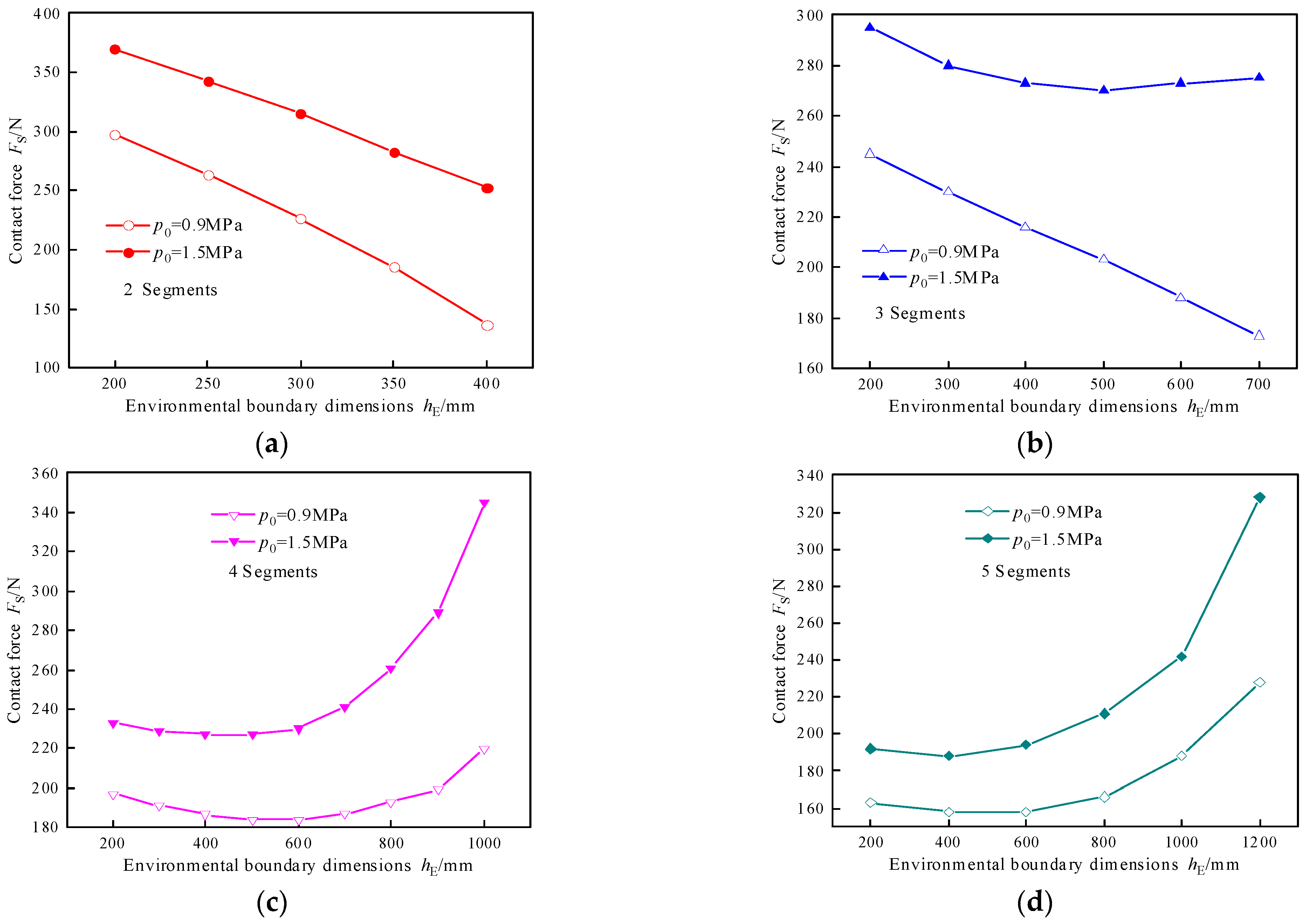
14]. When radial deformation alone cannot generate sufficient anchoring forces in the presence of environmental boundary confinements, modular robots typically employ coordinated multi-segment deformation to establish contact interfaces with surrounding structures. This bio-inspired strategy enables both anchoring stability and load-bearing capacity enhancement through optimized inter-segmental normal force distribution [
15,
16]. When operating in unknown or unstructured environments, modular robotic systems commonly utilize elephant trunk-inspired biomimetic architectures to achieve dexterous manipulation and adaptive obstacle avoidance. This design paradigm, informed by the kinematic principles of an elephant trunk, enables hyper-redundant motion in unstructured spaces through compliant segment interaction and distributed sensing [
17]. During real-world operations, the operational scenarios and locomotion requirements of continuum robots dynamically evolve as the system interacts with its environment. To address this challenge, we present a novel continuum robot featuring 3-DOF modular segments, which enables multi-modal kinematic configurations for adaptive operation across various environments.
In engineering practice, master–slave control architectures are commonly employed to enhance human–machine collaboration efficiency and mitigate operational complexity. The research on master–slave control methods mainly includes isomorphic master–slave control and non-isomorphic master–slave control. Yang et al. [
18] adopted an incremental master–slave control algorithm utilizing a position–orientation separation method, which overcomes the problems of isomorphism and workspace inconsistency between the master and slave while ensuring the same motion trend between them. Meanwhile, a safety assurance mechanism was integrated into the master–slave control architecture to eliminate the situation where the slave robot arm moves violently in a short period of time resulting from operator mis-operation. Ai Y et al. [
19] investigated the master–slave control architecture for heterogeneous surgical robots in minimally invasive surgery. Through systematic analysis of the master–slave configuration in MIS robotic systems, they proposed an incremental control methodology based on decoupling of gesture and positional control, effectively resolving the workspace incompatibility between master and slave manipulators arising from structural heterogeneity. Wang LQ et al. [
20] developed a novel 6-DOF isomorphic master–slave submarine manipulator for deep-water operational environments. A mapping framework was systematically established for the master–slave system. Comprehensive experimental evaluations demonstrated that the end-effector trajectories of the master and slave manipulators exhibited congruence. Zheng et al. [
21] proposed a novel master robot that utilizes a modular design approach. Based on the isomorphic systems of the master and slave robots, this design enables simple, intuitive, and stable control of the slave robot. An isomorphic master control allows for simple, intuitive, and stable control of robots, whereas non-isomorphic master control units facilitate the incorporation of safety mechanisms and motion range limitations, thereby ensuring the stable operation of the master–slave control system. Therefore, by combining the advantages of isomorphic and non-isomorphic master–slave control strategies and based on the structure and motion range of the three-degree-of-freedom segment, this paper designs an isomorphic master control unit and imposes motion constraints to ensure the stability of the master–slave control system.
This article proposes a continuum robot segment designed to be compact and modular, facilitating the formation of a continuum robot. The robot adapts to various environmental constraints based on the segment’s motion, degrees of freedom, and functions, and can pass through a confined space and operate in a structured environment.
The rest of this article is organized as follows. Firstly, the structural composition, integration, and modular design of the three-degree-of-freedom segment are presented. Subsequently, the motion forms of the continuum robot composed of this segment are analyzed, achieving earthworm-, snake-, and elephant trunk-biomimetic behaviors under varied constraints. The motion characteristics under these constraints are further detailed. Finally, isomorphic master–slave control system was designed for single-segment motion, and the system’s effectiveness and stability were experimentally demonstrated.
2. Three-Degree-of-Freedom Segment
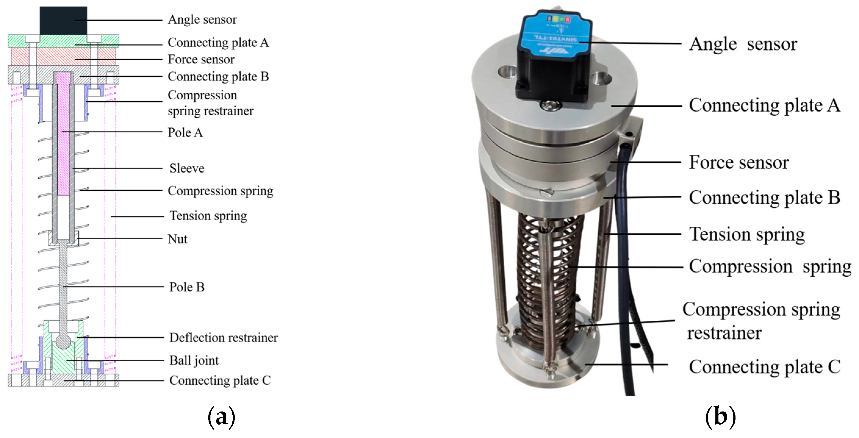
In order to achieve modular and integrated design of robot segments, an integrated solution is proposed, which tightly integrates the WHAMs inlet, valve, and sensor into the runner plate, as shown in
Figure 1.
Figure 1a,b show in detail the component composition, assembly, and series connection between segments. Specifically, a single segment is driven by four WHAMs and supported by spring. Four WHAMs form two pairs of orthogonal WHAM groups. One end of the WHAM is connected to the runner plate, while the other end is connected to the top plate or the runner plate of the next segment through a loose nut. Four pressure transmitters are integrated on the runner plate to monitor the working pressure of WHAMs. This design not only facilitates the assembly and disassembly of the segment, but also achieves the flexibility and scalability of the modular design. The valve is tightly connected to the runner plate through the insertion, as shown in
Figure 1c. The pressure difference control valves A and B in
Figure 1c correspond to the pressure difference control valves A and B, respectively, in
Figure 1d. The pump has a rated flow rate of 3.5 m
3/h, and its operating pressure does not exceed 8 MPa. During the working process, the fluid medium first passes through the total pressure control valve and then divides into two paths to enter pressure difference control valve A and pressure difference control valve B. The structures of pressure difference control valve A and pressure difference control valve B are completely identical and consist of one pressure inlet, one return outlet, and two pressure outlets. The two pressure outlets of pressure difference control valve A or pressure difference control valve B are, respectively, connected to two WHAMs, and these two WHAMs are a group. When the valve spools of pressure difference control valve A and pressure difference control valve B are centrally positioned, the working pressures at both outlets equalize (with four WHAMs operating at their initial working pressure), and adjusting the valve’s spool position induces contraction of the segment. When the valve spools of valves A and B deviate from the central position, the outlet pressures diverge, creating a pressure differential across the paired WHAMs. This results in one WHAM contracting while the other extends, producing segmental bending. The cornerstone of modular design resides in the runner plate, where the hydraulic circuitry is fully integrated. This integration enhances both compactness and operational efficiency of the modular segment. Inter-module hydraulic connections are established through a spring-shaped pipeline, which maintain flow continuity while improving system reliability and serviceability. This configuration enables a flexible, high-efficiency hydraulic system that satisfies the modular integration requirements of continuum robots. Additionally, the design facilitates system scalability and future upgrades. Physical parameters pertaining to segment are detailed in
Table 1.
4. Radial Constraint
Earthworms, annelid organisms with segmented bodies, achieve crawling motion through coordinated muscle activity across their segments.
Figure 3a illustrates the segment’s internal anatomy, showing circular muscles and longitudinal muscles. Their movement mechanism (
Figure 3b) operates as follows. During contraction phases, circular muscles relax while longitudinal muscles contract, causing setae to extend and anchor the segment. During elongation phases, circular muscles contract and longitudinal muscles relax, with setae retracting to propel the body forward. This alternating pattern of axial contraction/radial expansion and axial elongation/radial contraction between segments generates forward locomotion.
Multi-segment robots achieve in-pipe crawling through contraction/extension of WHAMs, emulating earthworm biomimicry via synchronized segmental state transitions. Four WHAMs operate under unified working pressure, contracting by overcoming axial compression spring forces to generate body shortening. As working pressure increases, these WHAMs exhibit three distinct operational phases:
Pre-contact Preparation Phase: WHAMs overcome spring resistance while maintaining radial clearance from the pipe wall;
Threshold Contact Phase: WHAMs establish initial pipe wall contact yet exhibit negligible interaction force;
Active Anchorage Phase: WHAMs maintain firm pipe wall engagement, generating both anchoring traction and structural load capacity.
Assuming that four hydraulic artificial muscles maintain a cylindrical configuration during contraction and that the working part experiences no axial displacement, the force–balance equation between a single segment and a pipeline under different contact states can be expressed as follows:
where,
Fmlow represents the axial contraction force of the WHAM under low working pressure;
h0 signifies the pre-compression of the spring;
hlow represents the compression variation of the spring when the WHAM is subjected to low working pressure;
Fmhigh denotes the axial contraction force of the WHAM under high pressure;
hhigh represents the compression variation of the spring when the WHAM is under high working pressure; Δ
F signifies the axial load of the module;
Fmrhigh represents the normal force between the WHAM and the pipeline inner wall under high working pressure;
μ denotes the friction coefficient between the WHAM and the pipeline inner wall; and
ks is the spring stiffness, which is related to its material and size. When the robotic segment’s structural parameters and pipeline inner-wall surface properties remain constant, the interfacial friction generated between WHAMs and the pipeline wall is exclusively governed by two factors: the working pressure of the WHAMs, and the pipeline material’s intrinsic frictional characteristics. This frictional resistance exhibits a direct positive correlation with increasing WHAM operating pressure. The test results revealed that within a pipeline with an inner diameter of 180 mm, the segment generates up to 8000 N of axial load capacity at a WHAM working pressure of 1.5 MPa. Under pipeline constraints, robots utilize the contraction and expansion functions of their segments to perform biomimetic crawling movements akin to those of earthworms, thereby simplifying the motion functions of the segments. Studies have already been conducted on the load-bearing capacity [
23], motion speed [
24], pipe diameter adaptability, and elbow adaptability [
25] of earthworm-mimicking robots under such constraints, and these aspects will not be re-analyzed here. The robot composed of these modules demonstrates exceptional load-bearing capacity under pipeline constraints, as evidenced by experimental testing.
6. Segmental Motion Characteristics of Elephant Trunk Movement
The segmental movement includes contraction and bending. To determine the range of motion for segmental contraction, an isolated contraction test was conducted. Without any working pressure differential, the initial working pressure was adjusted in increments of 0.25 MPa up to a maximum of 1.5 MPa, and the module contraction was measured. To minimize the risk of accidental errors, the experiments were repeated three times. The relationship between module contraction and initial working pressure
p0 is illustrated in
Figure 9, where it can be observed that as the initial working pressure increases, the amount of module contraction decreases. The maximum contraction of the module reaches 64 mm. This phenomenon is attributed to the driving characteristics of WHAMs.
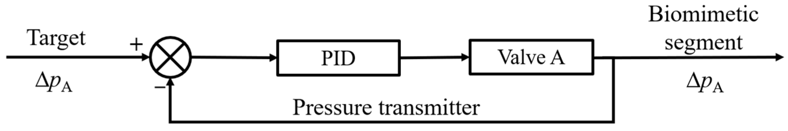
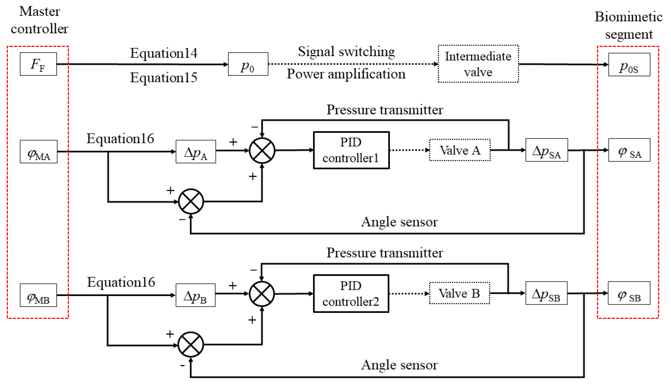
The bending behavior of biomimetic segments can be dissected into two interrelated components: (1) valve-actuated working pressure variations of WHAMs, and (2) working pressure-induced deformations that produce segmental movements. Consequently, the initial priority should be placed on investigating the closed-loop control characteristics governing the working pressure within biomimetic segments. The target was defined as the working pressure differential between the two outlet ports of either pressure difference control valve A or pressure difference control valve B. Theoretically, this pressure differential should equate to twice the magnitude of the WHAM’s working pressure variation from its initial working pressure. The control principles of pressure difference control valve A and pressure difference control valve B are identical. Taking pressure difference control valve A as an example, a PID controller was employed to regulate this pressure differential, and its control architecture is depicted in
Figure 10.
During the control process, the following operational sequence was executed:
The target differential was compared to the real-time measured operating pressure differential;
The discrepancy between these two values was computationally determined;
This error signal served as the input for the PID controller;
The controller adjusted the valve spool position based on the input signal;
Consequent adjustment of the working’s working pressure differential was achieved to converge on the target differential.
The operational position of the total pressure control valve spool was maintained by a spring mechanism. Due to identical valve structures for both pressure difference control valve A and pressure difference control valve B, their PID parameters were uniformly configured. To ensure the effectiveness of PID control, a genetic algorithm was employed to optimize the hyperparameters in the PID controller. Considering the computational complexity and accuracy of genetic algorithms, a target trajectory that ranged from a pressure variation of 0 steps to the maximum pressure variation was set as the evaluation criterion for the genetic algorithm. The specific method for hyperparameter optimization is as follows. The three hyperparameters,
kP,
kI, and
kD, in the PID algorithm were considered as the independent variables of the genetic algorithm, and the squared integral of the difference between the pressure–variation simulation result and the target trajectory was set as the evaluation variable. The optimal individual coefficient was set to 0.4, the population size was set to 20, the maximum evolutionary generation was set to 50, and the fitness function deviation was set to 1 × 10⁻
10. The optimized PID parameters obtained are shown in
Table 4.
Step response tests and sine following experiments were conducted to investigate the working pressure closed-loop control characteristics of biomimetic segments. The average of the two outlet pressures from pressure difference control valve A was designated as the initial operating pressure
p0. Initially, the outlet pressure differential between pressure difference control valve A and pressure difference control valve B was maintained at zero while adjusting the initial operating pressure to the target levels. Subsequently, a PID controller was implemented to stabilize the outlet pressure differential of pressure difference control valve B at zero, followed by closed-loop control characteristic evaluations for pressure difference control valve A’s outlet pressure differential. Three test conditions were established using 0.9 MPa, 0.8 MPa, and 0.7 MPa as initial operating pressures. The experimental scheme is detailed in
Table 5.
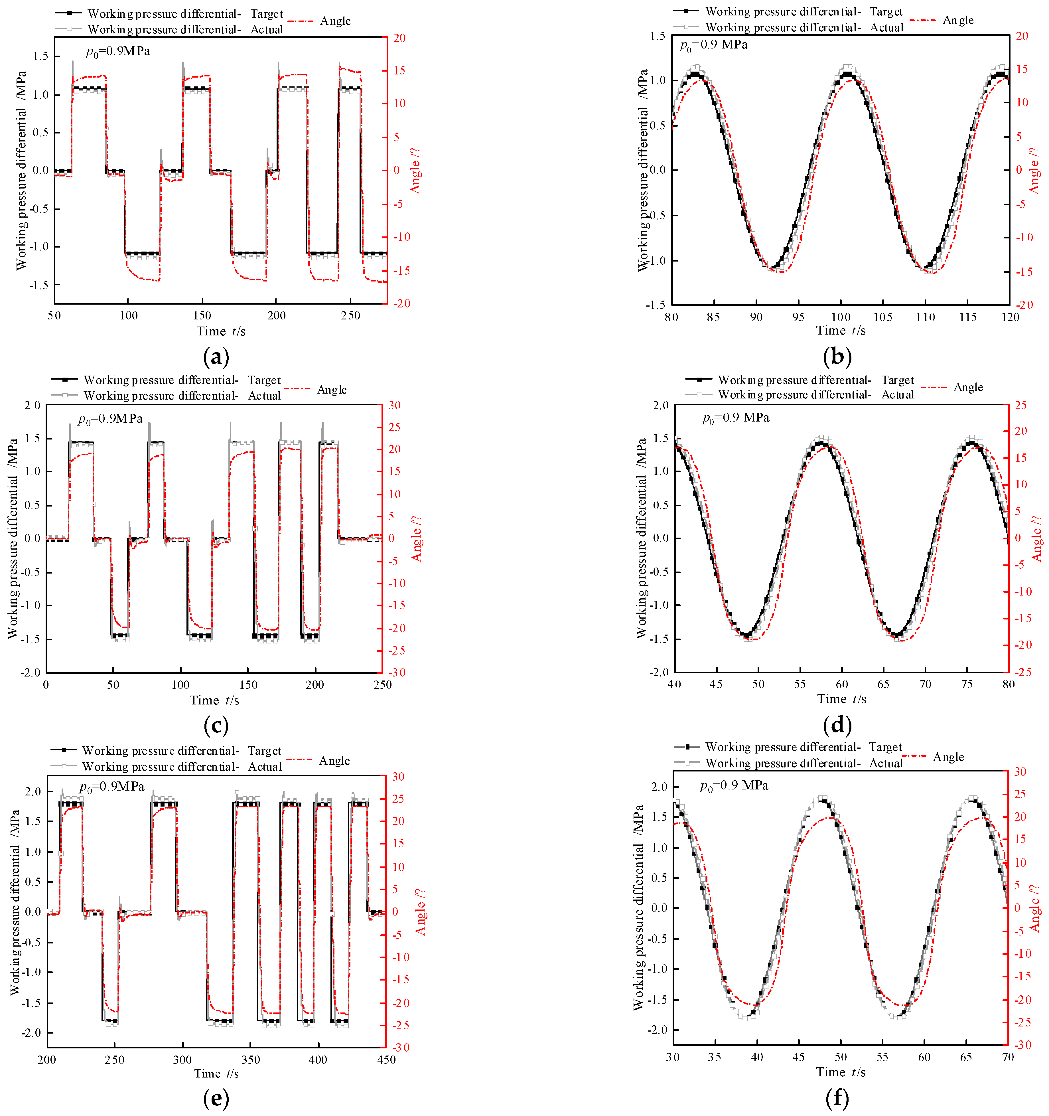
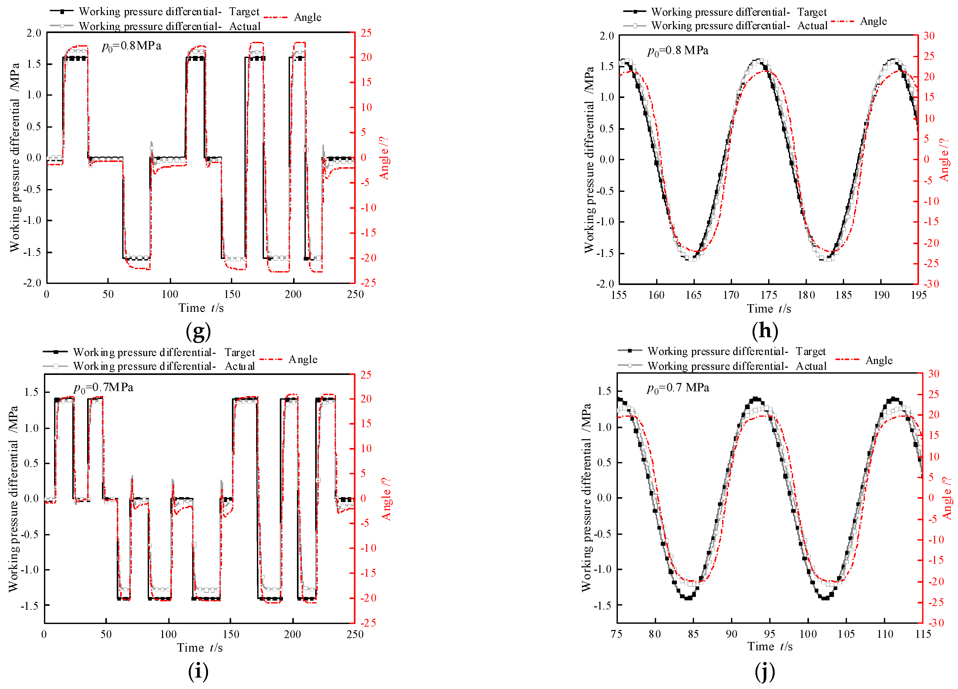
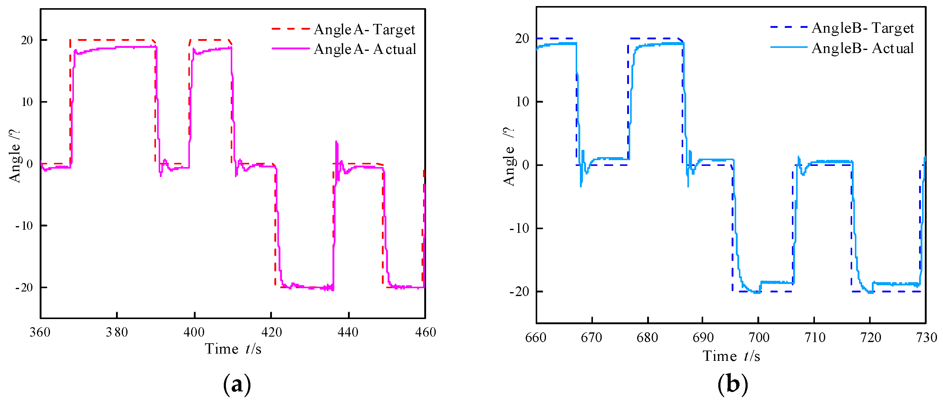
Experimental results for the step response test and sine following test are presented in
Figure 11. The corresponding closed-loop dynamic characteristics of the working pressure are quantified in
Table 6 and
Table 7. In the step response test, under identical initial operating pressures, the adjustment time diminishes with decreasing step amplitudes, while the overshoot magnitude correspondingly increases. This phenomenon arises due to the stationary valve spool of the intermediate valve maintaining a consistent flow capacity. During step amplitude reduction, the hydraulic fluid volume required for complete deformation of the hydraulic artificial muscle decreases. Consequently, under constant flow capacity, smaller step amplitudes correlate with shorter adjustment times but greater overshoot.
To illustrate, consider pressure difference control valve A under three conditions as follows: Initial working pressure = 0.9 MPa, step amplitude = 1.8 MPa; initial working pressure = 0.8 MPa, step amplitude = 1.6 MPa; initial working pressure = 0.7 MPa, step amplitude = 1.4 MPa (denoted as maximum step amplitude). With decreasing initial pressures at maximum step amplitudes, adjustment time increases. This behavior stems from two interrelated factors: valve spool position dependency, where lower initial pressures correspond to smaller spool openings, reducing the valve’s effective flow area. Conversely, higher initial pressures indicate larger spool openings and enhanced flow capacity. Pressure differential dynamics, where the rate of pressure change in hydraulic artificial muscles depends on the pre-to-post pressure differential. Larger differentials expedite fluid flow, shortening the pressure transition time. Collectively, these mechanisms prolong the adjustment time under maximum step amplitudes as initial pressure decreases.
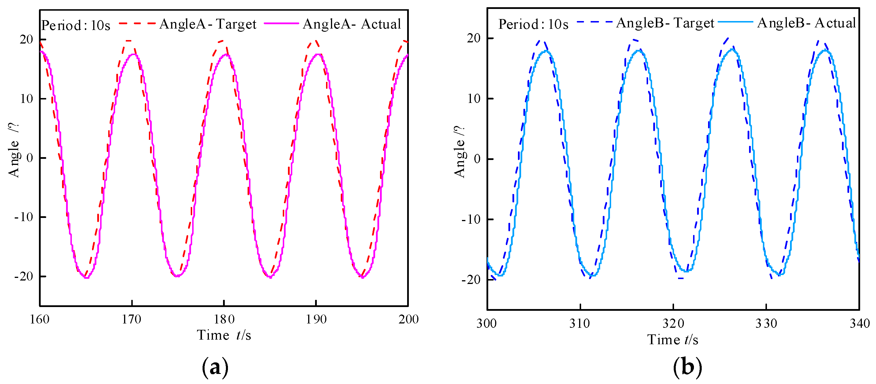
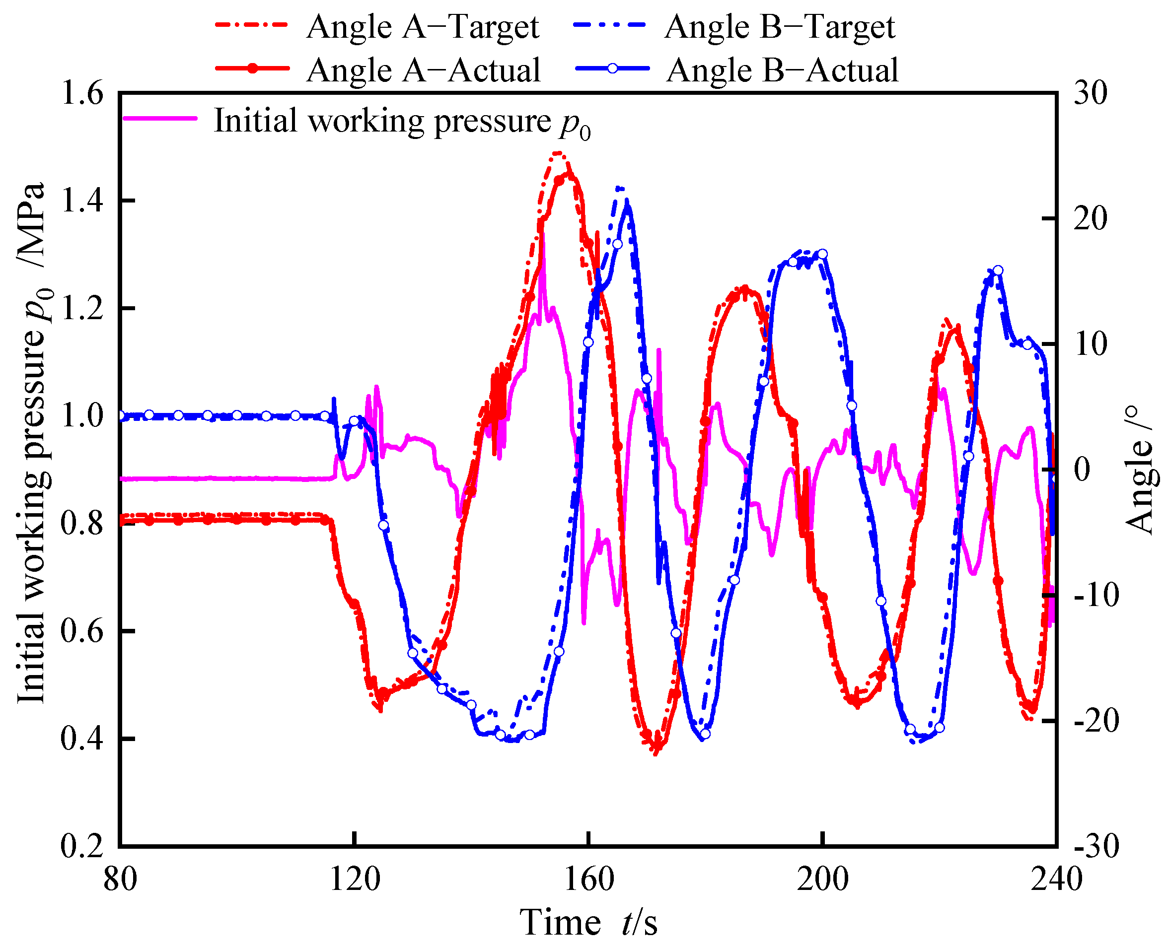
In the sine following test, as the initial working pressure increases, the phase lag of the tracking error also increases with the increase in amplitude. This is because the valve spool of the total pressure control valve remains stationary and its flow capacity remains unchanged. However, as the sine wave amplitude increases, the rate of change of the set pressure difference at the outlet of pressure difference control valve A per unit time increases, while the flow characteristics of the valve remain unchanged. Therefore, as the amplitude increases, the tracking error and phase lag increase synchronously. At the maximum amplitude, as the initial working pressure decreases, the tracking error decreases while the phase lag increases. As the total pressure control valve core moves, its outlet flow characteristics change, resulting in an increase in phase lag. However, at the same time, as the sine amplitude decreases, the rate of change in the set value of the internal valve outlet pressure difference between units also decreases. The combined effect of the two leads to a decreasing trend in tracking error. The sine following test with different periods are shown in
Table 8, which proves that the segments can be master–slave controlled at low frequencies.


