1. Introduction
In recent years, it was observed in the Czech Republic (CR) and Slovakia that, in car accidents on road bridge structures, there was relatively high material damage and sometimes also serious injuries to the passengers. In a mere visual assessment of the state of bridge steel barriers after traffic accidents, it was apparent that the technological procedure of the installation of bridge barriers was not observed; i.e., the anchoring depth of steel barrier posts in the concrete bridge ledge was not observed. It was proven that the longitudinal barriers have an important impact on the severity of consequences of traffic accidents on roads—provided, however, that they are correctly installed [
1,
2]. In some publications, it is possible to find cases where checking the installation of bridge barriers was required retrospectively, because traffic accidents usually have tragic consequences precisely on those stretches of roads. We tested several diagnostic methods which we used to assess the anchoring of barriers [
3,
4].
On the basis of this experience, greater attention started to be paid to the construction of individual structures, and investors started to request more complex checks of the individual steps of installation of bridge barriers by contractors. Due to there being several examples of cases in which a violation of technological discipline was proven, with the respective consequences, it is apparent that suppliers and contractors are paying greater attention to the installation of barriers. Unfortunately, the verification of the method of anchoring has not been upheld in legislation yet. A problem is also posed by the fact that, out of dozens of the assessed structures selected randomly in the CR and Slovakia, a lack of technological discipline was proven mostly in old bridge structures or in structures that are not found on main roads.
As has already been mentioned, there are several types of barriers: Concrete, steel, rope, and steel–wood. In the CR, for example, the Ministry of Transport has approved approximately 35 types of steel barriers by several manufacturers with a retention level of H1–H3 [
5]. These barriers differ from each other by their shape and the dimensions of individual components. They are selected on the basis of economic aspects and the time needed for their installation. It is taken for granted that all these barriers are certified and must withstand the minimum values of load given in the technical specifications of the Ministry of Transport [
6], and the steel must comply with the requirements of the ČSN EN 10025 [
7]. The main purpose of this road protection element is to hold and redirect an uncontrolled vehicle while ensuring adequate safety for the passengers in the vehicle as well as other road users [
5,
8]. The anchoring of these steel bridge barriers is particularly important, as they have to bear 1.5 times the plastic load capacity of the barrier posts, which is based on the characteristic value of the material yield strength [
5]. The location of the steel anchors is given by the data sheet of the manufacturer of the given barrier, which prescribes precisely the minimum depth of anchoring. The biggest problems in the installation of steel anchors into the bridge structure include drilling into the reinforcement of the concrete ledge or the insufficient quality of tools. These facts can lead to time pressures during implementation and thus to non-compliance with this technological requirement.
The present construction practice and experience of workers for contracted companies support the presumption that the existing legislation does not always require anchoring quality inspections during the implementation of a structure, which results in the fact that this lack of discipline still occurs when structures are built. The temporarily-used way of verifying the sufficiency of the depth of anchoring is based on a destructive method—the extraction of the steel bolt—which is relatively expensive and is only done on a very small number of representative samples [
9].
One of the diagnostic methods which is used widely both in mechanical engineering and in civil engineering is the ultrasonic method of testing [
10,
11,
12,
13]. There are several ultrasonic methods, and each of them is suitable for a different purpose. Mechanical engineering very often uses the ultrasonic pulse method by which it is possible to measure steel elements, their length or potentially their inner inhomogeneities, etc. This method has also proved very useful in the building industry, where it is used, for example, for checking welds, measuring the thickness of steel sheets, or measuring the length of steel bolts [
14,
15]. The method is purely non-destructive, and its biggest advantages are its repeatability of testing, the fact that it is not time-consuming, and its economic viability. On the basis of the first laboratory tests made, we proposed and developed a method of checking the anchoring depth, which was subsequently applied on-site.
2. Technological Procedure of the Installation of Anchors
Steel traffic barriers consist of a relatively complicated system of elements and joints. On roads, it is possible to come across various types of traffic barriers with varying levels of retention. The technological procedure of barrier installation must be certified by a competent authority and must include detailed steps for correct installation. In fact, it is possible to say that the basic principle of the installation of bridge barriers—i.e., their anchoring into a concrete ledge—consists of drilling holes with a sufficient depth as prescribed by the manufacturer, at given distances. One of the most frequent problems that can be encountered during traffic barrier installation is drilling into the reinforcement of the concrete ledge. In this case, it is necessary to drill through the steel rods in the concrete ledge in order to observe the depth of the drill. This necessity is often ignored; for example, due to inappropriate technology for drilling or due to the absence of suitable equipment. After drilling, the hole must be sufficiently cleaned so that impurities do not decrease the efficiency of the steel anchors, which also holds true for chemical and mechanical anchors. The requirements for the installation of anchors are more specific; the most frequent methods of anchoring include mechanical anchors (bracing), chemical anchors (glued), and an anchoring device being placed into the steel reinforcement of the future bridge concrete ledge. In the case of the third option, observing the depth of anchoring is almost certain. Although this is the most cost-effective way of anchoring bridge barriers, the first two methods are used more often. The principle of mechanical anchors consists in the activation of anchor—opening the steel ring after its placement into the drill hole, which ensures its cohesiveness with concrete. In the case of chemical anchors, chemical glue is applied into a cleaned drill hole, into which anchor bolt is subsequently placed [
16]. Chemical anchors are cut to the required length from the steel rods which are one meter long. When anchors are prepared manually, the prescribed total length of anchors is not always observed, which may be impossible to distinguish in visual examination of the anchors installation.
Concrete ledges are designed as sloping to prevent water retention on the structure and increase in the degradation of concrete. To flatten the plate of barrier posts, base materials are used, which flatten out the prescribed 1.5% transverse gradient of the ledge. The height of the base material is specified in the data sheets for the given type of barriers. Unfortunately, when a greater amount of the base material than necessary is used, the length of the anchor above the concrete ledge can often be almost doubled. In the case of chemical anchors, which are cut on-site, these shortcomings can be compensated for by a greater total length of the anchor.
3. Methodology of Ultrasonic Testing
In the building industry, two basic ultrasonic testing methods are used most frequently. The oldest and simplest of them is the passage method, the main feature of which is the measurement of passing acoustic pressure, or determining the time of ultrasonic waves passage through the environment examined. Two probes, one of which transmits ultrasonic pulses and the other of which receives them, are placed on the opposite sides of the environment examined, preferably coaxially. This method is used e.g., for an evaluation of the uniformity of concrete or for a determination of its elasticity modulus on the basis of the knowledge of the length of measuring base and of the determined velocity of passage of the ultrasonic wave. Its limitation is the necessity to measure by two probes, which can sometimes be a problem in the diagnosis of building structures. Another method is the pulse rebound method. The principle of the pulse method consists in transmitting pulses which are captured and represented by means of the so-called A-scan. The rebounded pulses return either to the same electroacoustic converter or to the receiving converter. Electrical signals created by the impact of ultrasonic pulses are amplified and brought to the vertical deflecting system of the display either directly or after their rectification and filtration. Filtration enables a clearer and more uncluttered representation on the screen but some details get lost. This method gives information about the size of the reflecting surface according to the height of the rebounded pulse (echo pulse). Apart from that, it is possible to determine the depth of the reflecting surface or the velocity of ultrasonic wave propagation from the time of echo pulse passage, and it is possible to estimate the character of the reflecting surface from the shape of the received echo pulses. The method is suitable for measuring elements embedded into concrete which can be approached from one side only. The input parameter is the knowledge of the velocity of ultrasonic wave propagation through the material tested.
The ultrasonic rebound method was chosen to assess the anchoring length of steel anchors embedded into concrete. At first, laboratory tests were carried out, in which the selected ultrasonic devices and thickness gauges were tested and their sensitivity and accurateness were assessed.
The ultrasonic devices and thickness gauges were tested with and without A-scans [
17]. For each of the total of 4 devices assessed, the sensitivity of measurement and especially the range were determined. In the laboratory tests it was proven that all the devices used measured the total lengths of the tested anchors reliably. Anchors with artificial defects, which are easily detectable by ultrasonic measurements, were also tested. These measurements were taken by means of direct ultrasonic probes with frequencies of 2 MHz, 5 MHz, and 10 MHz, which were selected as the most suitable for on-site measurements. Ultrasonic pulses are transmitted in the so-called narrow signal beam and it is possible to test steel anchors of lower diameters (6 mm, 8 mm) with a length of up to 500 mm. During calibration it was necessary to manually set the value of velocity with which the ultrasonic pulse propagates in steel. This value is determined according to ČSN EN 14127 at v = 5920 m/s ± 30 m/s [
18]. Due to the heterogeneity of the steel material from which steel bolts anchoring the barrier posts are made and due to the method of treatment, this value can vary for different types of bolts, which can cause certain inaccuracies in measurement. That is why it is useful, before testing the embedded anchors, to calibrate the device on the same type of steel bolts as the one that will be assessed on the bridge ledge. The inaccuracy of measurement caused, among other things, by various steel materials, can amount to ±1 cm.
4. Testing on the Selected Bridge Structures
Traffic accidents that occurred on the roads in the CR and Slovakia in recent years highlighted the described problem of the installation of retention systems, particularly on bridge structures. The selected bridge structures were diagnosed by means of ultrasonic pulse method. The measurement was carried out by means of the following devices: Zenotip+ by Proceq Switzeland [
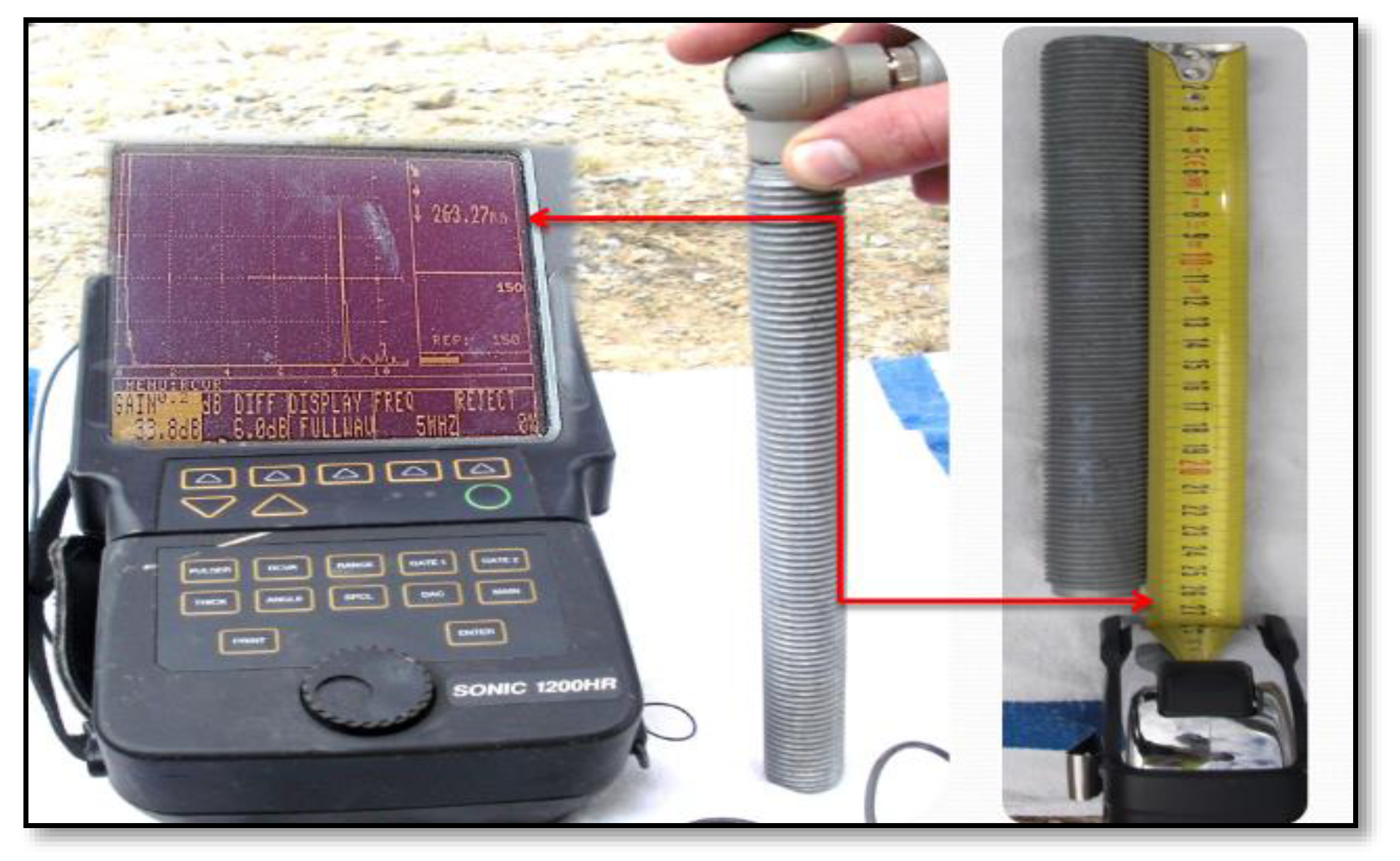
19] and SONIC 1200HR by STAVELY INSTRUMENTS INC. The method of calibration of the US device with an A-scan is shown in
Figure 1. The velocity of US wave propagation is set on the basis of the knowledge of the precise total length of the anchor. Further the strength of the transmitted pulse and the range are set in such a manner that it could be possible to observe also the second echo pulses. The correct setting of an ultrasonic device allows for assessing the total length of the steel anchor with an accuracy of 0.01 mm.
The calibration and setting of the device were carried out before the individual measurements on the bridge structures. The assessment was performed on the anchoring systems for traffic barriers of the following types:
Type A: One-side barrier JSPAM-2/H1, 2 × M16, min. depth of a drill hole for chemical anchor min. 160 mm.
Type B: Handrail barrier ZSKLS-I/H2, 2 × M24, min. depth of a drill hole for chemical anchor min. 190 mm.
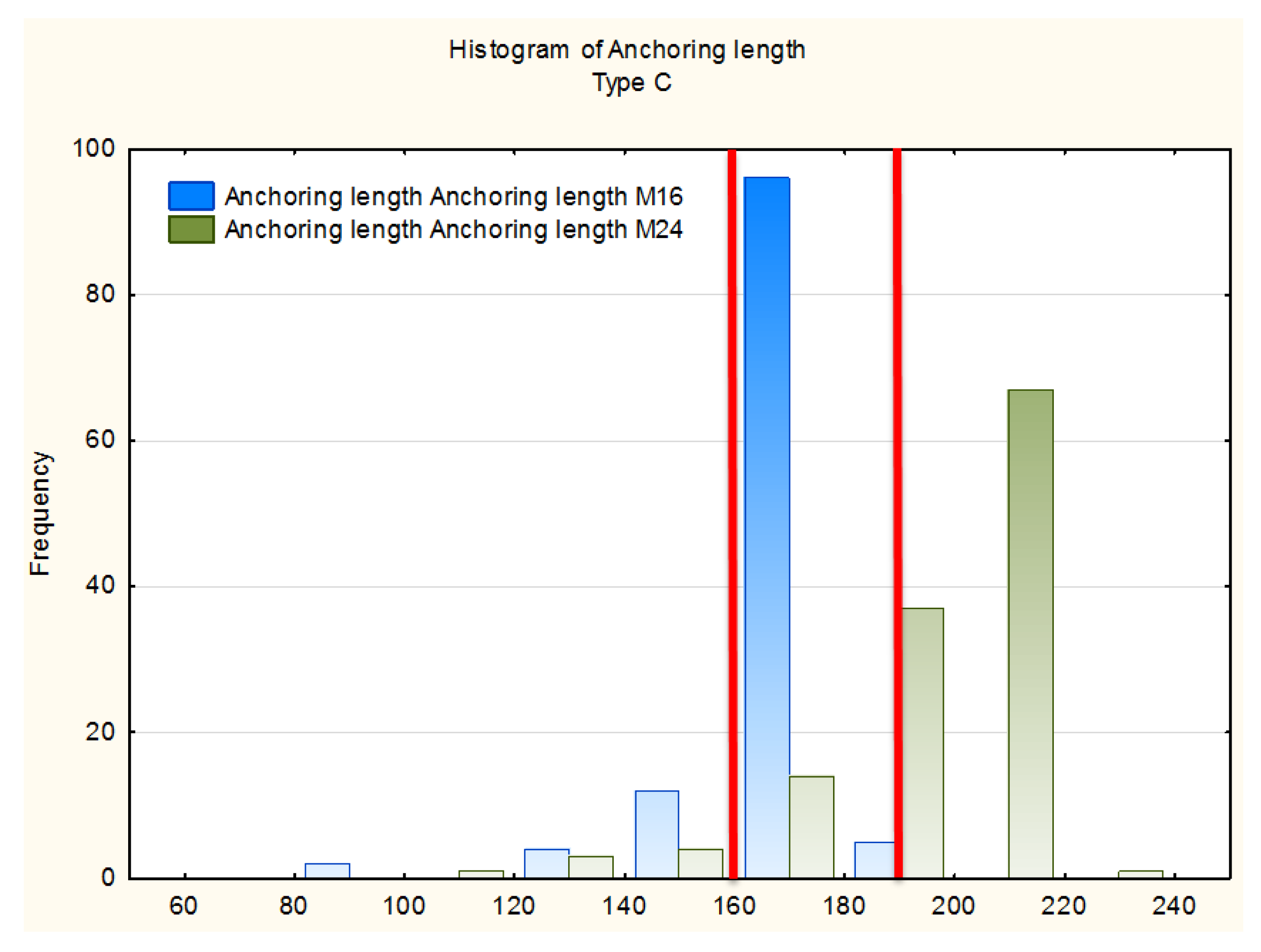
Type C: Handrail barrier ZSKLS/H2, 2 × M24 + 2 × M16, M24 with a min. depth of anchoring of min. 190 mm, for M16 with a min. depth of anchoring of 160 mm.
To achieve a better acoustic coupling between the ultrasonic probe which transmits and receives the ultrasonic pulse, we used an inert gel provided by the manufacturer of the ultrasonic thickness gauges. Some of the tested barriers were affected by corrosion and that is why it was necessary to apply a surface treatment so that corrosion and impurities could not affect the passage of ultrasonic pulse through the steel anchor and thus distort the measurement results. Subsequently, the gel was applied and the measurement taken. Then we measured the length of the steel anchor protruding over the concrete ledge with an accuracy of 1 mm. After the subtraction of these two values, we obtained the length of the anchor in the concrete ledge, i.e., the actual depth of anchoring. This value was then compared with the values prescribed in the applicable Technical specifications.
5. Evaluation
The quality check of steel barrier anchoring was performed on approximately 2000 steel anchors. The results were processed into a table and statistically evaluated. The statistical evaluation was done by means of box diagrams, which allow for the assessment of symmetry and variability of the data set (measured values) and of the existence of outliers or extreme values. It gives information about:
- -
The highest (maximum) value;
- -
the lowest (minimum) value;
- -
the range of values between the highest and the lowest value; and
- -
median.
The median is a value for which it is true that 50% of values are above, and 50% of values are below this value. The area of the 50% of middle values is called an interquartile range. Sometimes the box diagram is supplemented with the extreme values and outliers. They are usually marked with an asterisk or a cross. In the statistical evaluation, however, these values are not considered because they would deform the graph itself. From the statistical point of view, they are considered as wrong values which occurred for various reasons, e.g., due to a sudden change of conditions, measurement error, or inexplicable deviation.
Table 1 summarizes the total numbers of checked anchors on the selected bridge structures. Considering the fact that these were relatively long bridge structures, anchors were checked at random. For the sake of clarity, the table shows the total number of barrier posts and the number of checked posts for each type of anchoring—A, B, C.
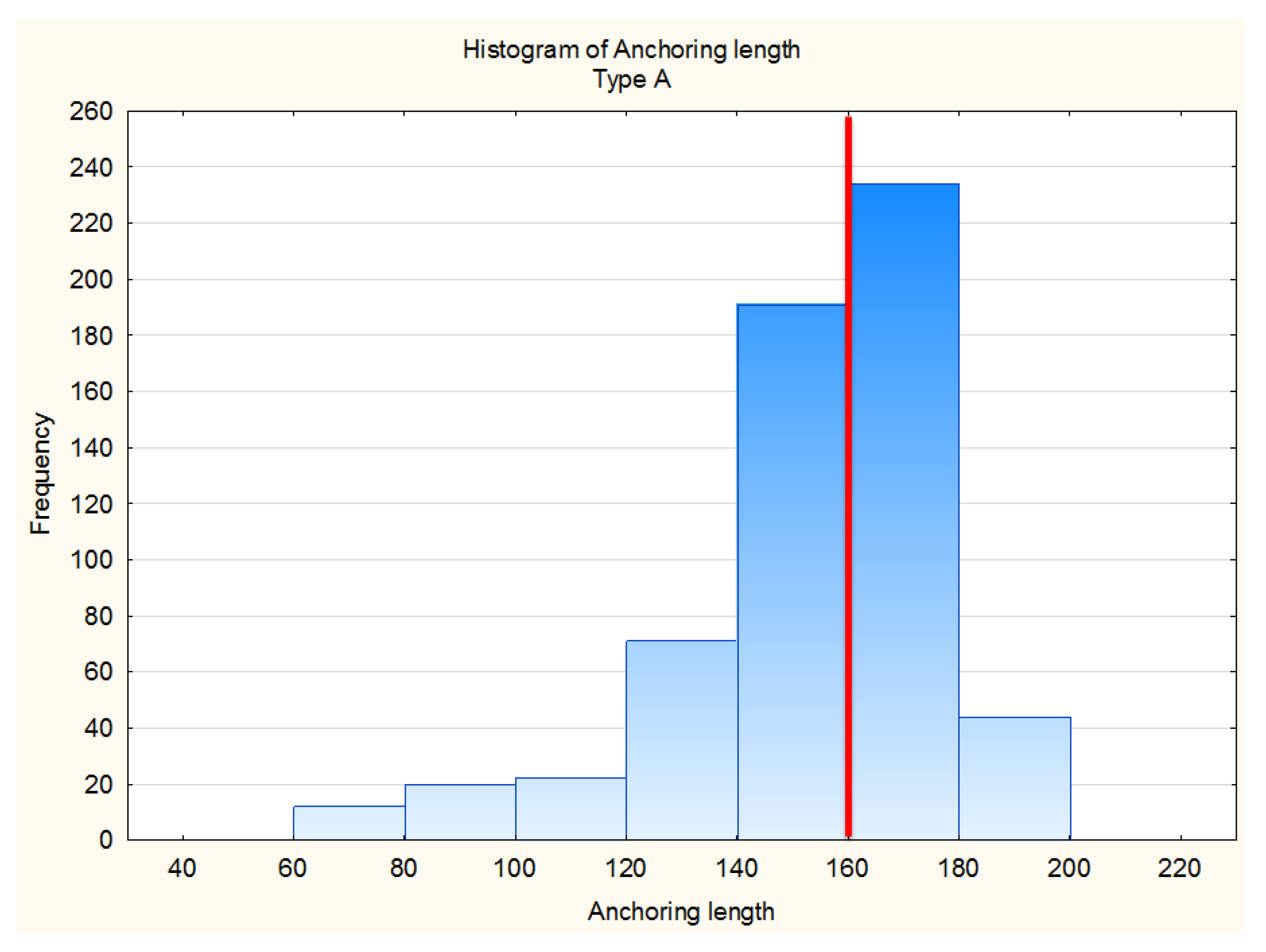
The following graphs show the measured values of anchoring lengths for the given anchoring systems obtained on 18 selected bridge structures. At first, we made a statistical evaluation by means of box diagrams for the type A anchoring, where the minimum anchoring depth, according to the applicable standards, is 160 mm. It is apparent from this graph that more than 50% of the measured values do not correspond with this minimum value,
Figure 2, which is also apparent from
Table 1. In the following histogram in
Figure 3 it is possible to see a relatively large dispersion of the measured values. The lowest values measured ranged around up to approximately 70 mm.
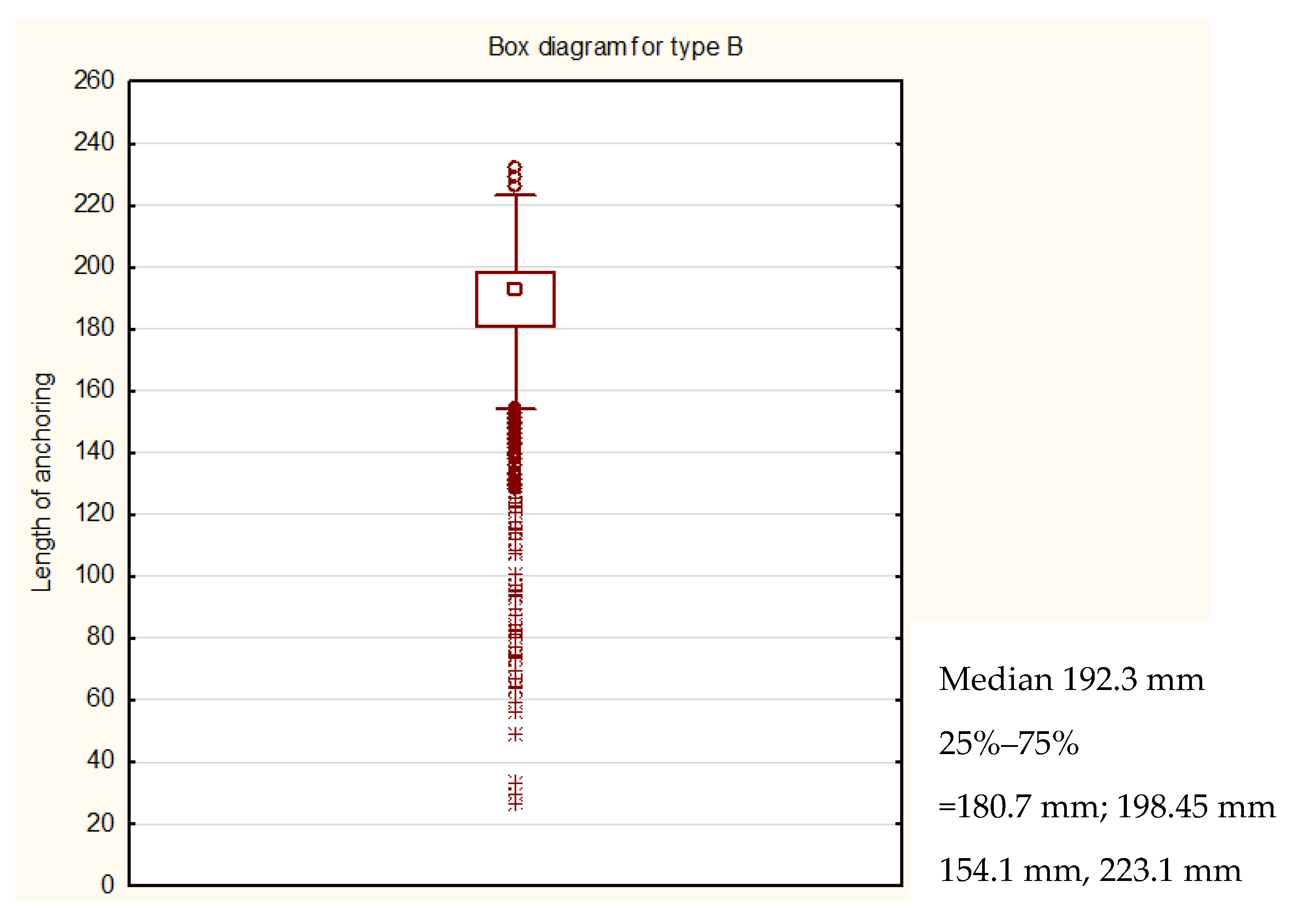
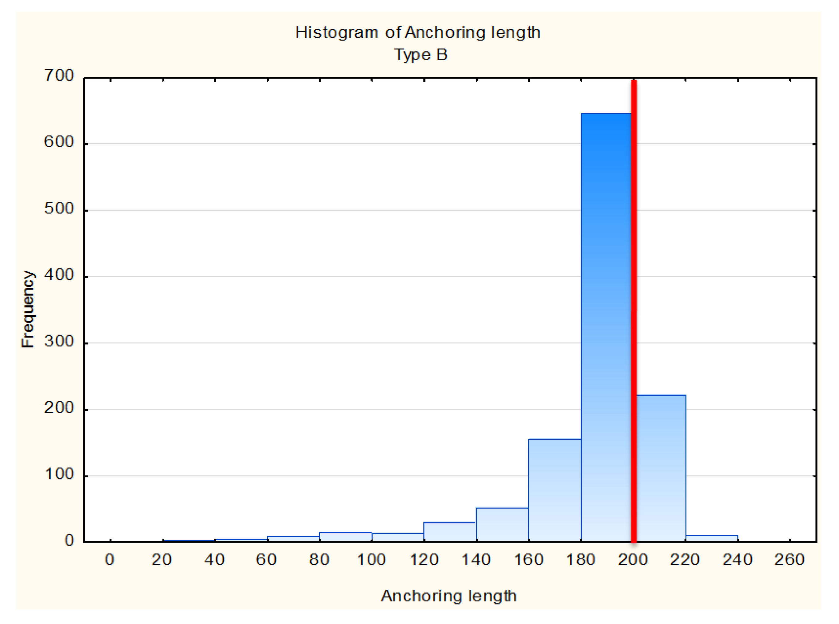
Figure 4 shows the evaluation of the anchoring length for the type B anchoring system from 60 checked structures. A significant spread of values is apparent at first sight. The median value equals 192.3 mm, i.e., 50% of the measured values are lower. At the same time, it is possible to conclude that there is a large number of outliers which can distort the statistical evaluation—these values are not considered for analysis. For this reason, two types of graphic representation were chosen.
In
Figure 5 it is possible to see that the highest number of the measured values of anchoring depth ranged from 180 mm to 200 mm. Although the deviations from the prescribed minimum anchoring length could be regarded as not too high, the assessment performed proved that the technological procedure of the installation was not observed. According to
Table 1, 35% of the cases measured do not comply with the technological procedure, which is a relatively large number considering the number of anchors checked.
For the type C anchoring system, where the barrier posts are anchored by two steel bolts M16 and by two bolts M24, only a histogram was used. This type of anchoring was found in 6 bridge structures only, therefore the statistical evaluation of compliance with the anchoring length may not be as important as in the previous cases. Nevertheless, it is possible to say that approximately 17% of the evaluated anchors did not correspond with the prescribed anchoring lengths,
Figure 6.
6. Conclusions
The paper gives a detailed description of the methodology of ultrasonic measurement, which is used for determining the total length of steel bolts of various diameters and lengths. It was proven that this method is more than suitable for assessing the anchoring depth of steel anchors anchoring steel barriers to the concrete bridge ledges. As is apparent from the presented measurement results, this issue is highly topical. It was proven that sometimes more than 50% of the checked anchors were not satisfactory, which some authors view as an alarming number from the point of view of a threat to the safety of traffic on the roads.
From the graphic processing of the data obtained, it is possible to conclude that in the selected structures, the technological procedure of installation was disregarded systematically. Another cause can be found in the missing regulatory requirement on performing the check of anchoring, especially in the new bridge structures. Considering the fact that this is part of the road protection systems, the issue should be given much more attention. The advantages of the diagnosis of steel barriers by means of ultrasonic pulse method include mainly its low time-consumption, the economic aspect, and the high accuracy of measurement.
Author Contributions
Conceptualization, T.K. and A.O.; methodology, T.K., A.O. and J.L.; software, T.K.; validation, T.K. and J.L.; formal analysis, T.K. and A.O.; investigation, T.K. and J.L.; resources, T.K.; data curation, T.K. and J.L.; writing—original draft preparation, T.K. and A.O.; writing—review and editing, T.K. and A.O.; visualization, T.K.; supervision, A.O.; project administration, T.K. All authors have read and agreed to the published version of the manuscript.
Funding
This paper has been prepared under project No. LO1408 “AdMaS UP—Advanced Materials, Structures and Technologies”, supported by the Ministry of Education, Youth and Sports under the “National Sustainability Programme I”.
Acknowledgments
Authors would like to thank to Anton M. for support.
Conflicts of Interest
The authors declare no conflict of interest.
References
- Chitturi, M.V.; Ooms, A.W.; Bill, A.R.; Noyce, D.A. Injury outcomes and costs for cross-median and median barrier crashes. J. Saf. Res. 2011, 42, 87–92. Available online: http://linkinghub.elsevier.com/retrieve/pii/S0022437511000211 (accessed on 21 December 2019). [CrossRef] [PubMed]
- Martin, J.L.; Mintsa-Eya, C.; Goubel, C. Long-term analysis of the impact of longitudinal barriers on motorway safety. Accid. Anal. Prev. 2013, 59, 443–451. Available online: http://linkinghub.elsevier.com/retrieve/pii/S0001457513002522 (accessed on 21 December 2019). [CrossRef] [PubMed]
- Chintakunta, S.R.; Boone, S.D. Non-destructive inspection protocol for reinforced concrete barriers and bridge railings. AIP Conf. Proc. 2014, 1581, 852–859. [Google Scholar] [CrossRef]
- Petro, M.; Ďubek, M. Possibilities of assessment of insulation thickness in ETICS using dielectric parameters of strata in composite construction. Czech J. Civ. Eng. 2018, 4, 95–101. Available online: http://www.scientificjournals.eu/magazine/2018/CJCE_2018_02.pdf (accessed on 21 December 2019).
- Technické Podmínky Ministerstva Dopravy TP 114. In Politika Jakosti Pozemních Komunikací; Ministerstvo Dopravy ČR: Praha, Czech Republic, 2015. Available online: http://www.pjpk.cz/data/USR_001_2_8_TP/TP_114a.pdf (accessed on 21 December 2019).
- Technické kvalitativní podmínky staveb pozemních komunikací: Kapitola 19 ocelové mosty a konstrukce. Pjpk.Cz Politika Jakosti Pozemních Komunikací Praha: Ministerstvo Dopravy ČR. 2015. Available online: http://www.pjpk.cz/data/USR_001_2_6_TKP/TKP_19_A___15.pdf (accessed on 21 December 2019).
- Czech Standards Institute. Hot Rolled Products of Structural Steels: Part 1: General Technical Delivery Conditions; ČSN EN 10025; Czech Standards Institute: Praha, Czech Republic, 2005. [Google Scholar]
- Noh, M.H. Crashworthiness Evaluation of Bridge Barriers Built with Hot-dip Zinc-aluminium-magnesium Alloy-coated Steel. J. Korea Acad. Ind. Coop. Soc. 2016, 17, 171–176. Available online: http://koreascience.or.kr/journal/view.jsp?kj=SHGSCZ&py=2016&vnc=v17n3&sp=171 (accessed on 21 December 2019). [CrossRef]
- Guideline for European Technical Approval of Metal Anchors for Use in Concrete: Part 5; European Organisation for Technical Approvals: Brussels, Belgium, 2006; Available online: https://itec.cat/certificacio/files/ETAG_001_part1-amendment-07-11-13.pdf (accessed on 21 December 2019).
- Xiao, Y.F.; Zhang, D.H.; Liu, L. Internal Imperfection Detection of Concrete Composite Component Using Ultrasonic Method and Impact-Echo Method. In Advanced Materials Research; Trans Tech Publications: Switzerland, 2013; pp. 1046–1050. Available online: http://www.scientific.net/AMR.639-640.1046 (accessed on 21 December 2019). [CrossRef]
- Song, H.; Popovics, J.S. Characterization of steel-concrete interface bonding conditions using attenuation characteristics of guided waves. Cem. Concr. Compos. 2017, 83, 111–124. Available online: http://linkinghub.elsevier.com/retrieve/pii/S0958946517302287 (accessed on 21 December 2019). [CrossRef]
- Lin, Z.B.; Azarmi, F.; Al-Kaseasbeh, Q.; Azimi, M.; Yan, F. Advanced Ultrasonic Testing Technologies with Applications to Evaluation of Steel Bridge Welding—An Overview. Appl. Mech. Mater. 2015, 727–728, 785–789. [Google Scholar] [CrossRef]
- Yu, L.; Giurgiutiu, V.; Ziehl, P.; Ozevin, D.; Pollock, P. Steel bridge fatigue crack detection with piezoelectric wafer active sensors. Sens. Smart Struct. Technol. Civ. Mech. Aerosp. Syst. 2010, 7647, 76471Y. [Google Scholar]
- Kharrat, M.; Gaillet, L. Non-destructive evaluation of anchorage zones by ultrasonics techniques. Ultrasonics 2015, 61, 52–61. Available online: http://linkinghub.elsevier.com/retrieve/pii/S0041624X15000748 (accessed on 21 December 2019). [CrossRef] [PubMed]
- Bingol, Y.; Okeil, A.M. Ultrasonic Signal Characteristics for Nondestructive-Yield Detection in Steel Structures. J. Mater. Civ. Eng. 2015, 27, 04014271. Available online: http://ascelibrary.org/doi/10.1061/%28ASCE%29MT.1943-5533.0001218 (accessed on 21 December 2019). [CrossRef]
- Cihal-omo Jaroslav Číhal—OMO: Jaroslav Číhal—OMO. 2016. Available online: http://www.cihal-omo.cz/kotevni-prvky-mostnich-svodidel-zpusoby.html (accessed on 21 December 2019).
- Hobst, L.; Koudelka, M.; Láník, J.; Vítek, A.L. Review of possibility of usage of ultrasonic thicckness gauges for checking the length of anchorsin concrete. In Beton TKS s.r.o.: Rehabilitation and Reconstruction; Beton TKS s.r.o.: Praha, Czech Republic, 2011. [Google Scholar]
- Standards Institute. Non-Destructive Testing—Ultrasonic Thickness Measurement; ČSN EN 14127; Standards Institute: Praha, Czech Republic, 2011. [Google Scholar]
- Available online: https://www.proceq.com/ (accessed on 21 December 2019).
© 2020 by the authors. Licensee MDPI, Basel, Switzerland. This article is an open access article distributed under the terms and conditions of the Creative Commons Attribution (CC BY) license (http://creativecommons.org/licenses/by/4.0/).
