Article

Safety Issues in the Seismic Design of Secondary Frameless Glass Structures

Department of Engineering and Architecture, University of Trieste, Piazzale Europa 1, 34127 Trieste, Italy
*
Author to whom correspondence should be addressed.
Safety 2019, 5(4), 80; https://doi.org/10.3390/safety5040080
Submission received: 26 September 2019 / Revised: 30 October 2019 / Accepted: 31 October 2019 / Published: 6 November 2019

Abstract

:
Glass is largely used in buildings, in the form of an innovative and versatile material. Both for novel and existing constructions, secondary glass systems are frequently realized to interact with primary components of different materials. In most cases, the structural challenge deriving from the intrinsic brittleness and vulnerability of glass is efficiently controlled via laminated (LG) multi-layer sections. However, further potential risks for people should be properly minimized, like for example, in the presence of extreme loads. This is the case of seismic regions, where dedicated calculation methods are required to accommodate displacement and resistance demands, but design specifications are rarely provided by existing standards for earthquake resistant buildings. Even more attention is needed for frameless glass systems in which the bracing members (i.e., continuous frames, cable-nets, etc.) are reduced to a minimum, in favour of metal point connections (i.e., bolts and mechanical fixings, friction clamps, etc.). This paper aims at discussing the current design requirements for the seismic performance assessment of these relatively simple but challenging structural solutions, with careful consideration for the Italian scenario, where a practical support for design can be found in the CNR-DT 210/2013 technical document. Based on a case-study system, major issues, open questions and uncertainties or critical aspects for the seismic analysis and design of secondary frameless glass assemblies are thus emphasized.

1. Introduction

Glass is increasingly used in buildings and constructed facilities. Typical applications can be found in the form of curtain walls, innovative “adaptive” facades or even load-bearing members (beams, columns), shear walls intended to contribute to the structural performance of the building they belong to or complex stand-alone systems (see for example Figure 1 and [1,2]). Given the intrinsic mechanical features of glass in buildings (and its combination with other constructional materials), dedicated design methods are required for ordinary loads, and even more to withstand extreme events like earthquakes [3,4,5].
From a practical point of view, within a Limit State Design (LSD) approach, it is in fact well known that seismic-resistant structures must offer adequate safety and serviceability capacities in operational conditions, namely represented by:
(1) A limited probability of collapse at the Ultimate Limit State (ULS), and
(2) An appropriate accommodation of displacements, at the Serviceability Limit State (SLS).
In such a scenario, the typical need of robustness, redundancy, and ductility of glass structures are further enforced [6,7].
Besides that, however, no detailed attention is given by existing standards for buildings to assess (or improve) the performance of glass structures in seismic regions (see for example the Eurocode 8 for earthquake-resistant constructions [8]). The latter (and others) solely provides general recommendations that can be applied to “non-structural” components, without specific attention for glass. The Eurocode groups in fact together a series of so-called “appendages” (i.e., parapets, gables, antennae, mechanical appendages and equipment, curtain walls, partitions, railings) requiring that “together with their supports, they should be verified to resist the design seismic action” (based on simplified, local seismic analysis). Accordingly, the full design process should be aimed at ensuring “adequate clearance” for them, that is gaps and intrinsic flexibility allowing to accommodate the relative displacements of the primary structure. It is finally specified, for “non-structural elements of great importance or of a particularly dangerous nature”, that the seismic analysis shall be based “on a realistic model of the relevant structures, and on the use of appropriate response spectra derived from the response of the supporting structural elements of the main seismic resisting system”. Such a lack of detailed specifications for innovative constructional materials like glass typically reflects in over-designed load-bearing members and fasteners, so that possible hazards for the occupants could be avoided in the case of seismic events.
In this paper, special attention is given to the seismic performance assessment of secondary frameless glass systems. In most of the cases (i.e., traditional buildings), they do not modify the stiffness and resistance of the primary buildings they belong to. However, secondary assemblies (and their fasteners) in seismic conditions must in any case satisfy some rigid structural design requirements, both at the local and global levels. Even more attention and advanced design methods are required for secondary glass systems that can affect the mechanical properties of primary assemblies (i.e., lightweight structures, etc.).
The paper, in this regard, is application-oriented and aims at emphasizing some relevant issues that should be taken into account for the safe seismic design of relatively simple but vulnerable systems like frameless glass structures. The existing design recommendations are thus commented, with a specific focus on the Italian scenario, where the CNR-DT 210/2013 technical document [9] represents an efficient tool in support of designers. While the guideline is not prescriptive, it provides a relevant input and background for the European scenario, filling some gaps of the NTC2018 Italian standard for constructions [10] as well as of the Eurocode 8 [8], towards the harmonization of international standards for structural glass (see for example [11,12]) and the development of a dedicated Eurocode [13]. Key definitions and steps for a seismic design approach are thus first recalled from [9,10]. A case-study system is also presented in the paper, consisting in a secondary frameless partition structure realized in 2018 in Trieste (Italy), in the framework of a historical building. As shown, besides the availability of an exhaustive technical document, some uncertainties can still arise in the definition of key parameters for the seismic analysis and design of glazed structures, fasteners included.

2. Research in Support of Seismic Design

At the European level (and worldwide), most of the ongoing research efforts are aimed at implementing and/or optimizing appropriate design rules for a relatively innovative constructional material like glass [9,10,11]. While a multitude of loading and boundary conditions is taken into account in the literature, however, the intrinsic versatility of glass applications in buildings continuously renovates the need of further research efforts. This lack of appropriate background includes also the seismic performance of glass structures.
Most of the existing studies and research projects of literature are in fact focused on the seismic assessment of specific constructional systems. This is the case of ordinary glass curtain walls, where glass panels are fully braced by continuous framing members, and merely intended as infill components (see for example [14,15,16]). Several efforts have been also spent in the past for the design and analysis of glass structures with bolted connections (see for example [17,18,19,20,21]), but only few research investigations are available for point-supported facades in earthquake-prone regions (i.e., [22,23]), with a focus on the intrinsic flexibility under in-plane seismic loads. The dissipation capacity of ordinary curtain walls under seismic events was partly assessed also in [24,25] with the support of experiments, while an efficient, dissipative timber-glass composite shear wall was proposed in [26,27] for earthquake resistant buildings.
In [28,29], it was demonstrated that even ordinary glass curtain walls can be efficiently involved in the dynamic response of multi-storey buildings under seismic events, as well as multi-hazards in general. Based on special dissipative connectors, the feasibility of a “distributed-Tuned Mass Damper (TMD)” concept was numerically explored, giving evidence of certain potential benefits for both the primary building and also for the glass facade components. The same research study highlighted, however, the need of a detailed design of the involved connectors, to avoid inconsistent stress/displacement demands under seismic loads. Later on, Santarsiero et al. [1] assessed the seismic performance of glass portal frames, proposing some estimates for a reliable q-behaviour factor. Taking advantage of optimally designed restraints, it was shown that glass frames can efficiently act under severe seismic events.
Certainly, the design of fasteners and anchoring systems represent a key challenge for glass structures in seismic regions. The primary goal of design is in fact to prevent stress peaks in glass, due to the seismic deformations of the main structure they belong to, and large deformation capacity. In [30], to this aim, modified spider connectors were proposed for point-supported glass facades, so as to accommodate the deformations of primary buildings during earthquakes. While these connectors provide a rigid support in the vertical direction, their key feature can be exploited under in-plane lateral loads. Tacking advantage of slotted holes, see Figure 2, it was in fact proved in [30] that point-fixed glass panels—even belonging to buildings subjected to moderate seismic events—are not susceptible to relevant stress peaks. Full-scale experimental tests carried out on prototypes of point-supported façade panels showed in fact that large drift demands can be efficiently satisfied without any kind of damage in glass. Even under an imposed seismic overload and large in-plane deformations (up to 0.02 times the height of prototypes), no visible fracture was observed in glass. The same design concept was then implemented in a monumental glass dome (San Jose Civic Center (San Jose, CA, USA)).
Later, March [31] proposed a bespoke “pinned/rocking” steel restraint for glass columns. As also in accordance with [30], the goal was to provide a certain deformation capacity to glass columns intended to brace a facade wall system, thus withstand vertical and bending loads in service conditions (rigid pin), but at the same time, to accommodate the building deformations and not fracture during severe seismic events (pivot).
To this aim, a base connection system was properly designed in the form of a steel shoe rigidly connected to the ground foundation (Figure 3a), including a central steel notched block to act as a pin for the glass column, and a surrounding soft layer of epoxy resin, so as to offer a certain deformation capacity (Figure 3b). Such a solution was efficiently implemented in 5.5 m tall glass columns for a building in Standford (Palo Alto, CA, USA, see Figure 3c).

3. Seismic Design of Glass Systems Based on the CNR-DT 210 Guide

3.1. Basis of Design

The CNR-DT 210/2013 document [9] includes an extended pre-standard study on the performance of glass structures and components. The guide is not prescriptive but it actually represents one of the most detailed guides in support of glass designers, given the lack of specific regulations in the Italian Technical Standards for Constructions (NTC2018 [10]) or other exhaustive international standards [11,12]. In addition, several sections of the CNR guide are supporting the in-progress Eurocode 10 for glass structures, see Figure 4 and [4,13].
Among others, Section 4.4 of the CNR document specifically focuses on seismic design actions and general rules for safe design purposes of glass structures in earthquake prone regions.

3.2. Consequences Classes and “Secondary” Structural Components

Different levels of seismic analysis and design are recommended for glass systems/elements that can have a primary constructional role. These methods are strictly related to the class of use and consequences class (CC) of the system/part to verify.
Also in line with Eurocodes, the guide excludes from the analysis all the glass elements that do not have any kind of structural role, and basically fall in the CC0 (see also §3.2.1 and EN1990:2002-Annex B1 [32]). Accordingly, a given glass system/element is expected to belong to classes CC1 to CC3 when (see also Table 1):
  • CC1 = glass failure has limited consequences in terms of loss of human life and small or negligible consequences in economic, social or environmental terms. CC1 includes glass structures/elements in buildings characterized by occasional presence of people. The probability of failure is Pf,50 = 5.83 × 10⁻⁴ and Pf,1 = 1.335 × 10⁻⁵ (with 50 and 1 the period (in years) to which Pf refers);
  • CC2 = failure has medium consequences for human life, but considerable consequences in economic, social and environmental terms. Typical examples are glass structures/elements for residential/office buildings. In this case, Pf,50 = 6.2353 × 10⁻⁵ and Pf,1 = 1.3 × 10⁻⁶;
  • CC3 = failure has high consequences in terms of human life and very great consequences in economic, social terms. CC3 includes glass systems belonging to public buildings and places susceptible to overcrowding, but also stand-alone glass structures (Pf,50 = 8.54 × 10⁻⁶, Pf,1 = 9.96×10⁸).
An important aspect of [9], see Table 1, is the definition of specific CC levels for the pre-failure (pre-F) and post-failure (post-F) analysis of a given glass element. These conditions correspond respectively to SLS and ULS verification of the unfractured glass section (pre-F), or to the Collapse Limit State (CLS) analysis of the fractured element (post-F). The CLS condition, in particular, must assess that a given damaged glass element remains in use for a short period of time (i.e., to rearrange its replacement). Accordingly, the CLS design actions are conventionally rescaled (“pillars” excluded, see Table 1) based on a reduced return period. Following [11], the CNR design concept has been further elaborated with the novel proposal—in adjunction to “classical” SLS and ULS conditions for unfractured glass—of the so-called Fracture Limit (FLS) and Post Fracture Limits States (PFLS).
As far as Table 1 is taken into account, it is clear that the appropriate classification (and thus verification) of glass systems/independent elements can be implicitly related to possible uncertainties for designers. Special care is hence required for the definition of the appropriate CC, in favour of safe verifications. On the other side, the assumption of extremely conservative performance limits could result in non-efficient design, with marked increase of costs. Within the full design process, a key role is then assigned to glass itself, but also to the detailing of connectors and restraints. A minimum gap (i.e., clearance) is in fact mandatory, to ensure that relative deformations of a given glass system/element (with respect to the bracing system or primary building) could not manifest in premature fracture, under ordinary loads and even more in case of earthquakes. For seismic design, the distinction of the CNR guide is between (a) “secondary” structural elements or (b) glass elements that have a relevant structural role under seismic events (§4.4.1 [9]). In case (a), glass elements can be disregarded in the global seismic analysis of the primary system, because they are expected to offer a negligible contribution towards the design horizontal forces. However, a clear classification and quantitative definition of “secondary” elements is still missing in the CNR guide. According to NTC2018, §7.2.3 [10], the stiffness and resistance contributions of these components could be reasonably neglected from global seismic analyses as far as they do not exceed the 15% part of the primary construction. Another issue is related to the performances that secondary elements must satisfy, given that they are in any case expected to withstand vertical loads and accommodate the main deformation of the primary building, under the most unfavourable (CLS) seismic combination of loads. In case (b), the CNR document includes glass systems and components that have a relevant stiffness/resistance contribution, or consist of stand-alone/“special” glass structures. All these solutions fall in CC3, and even minor damage must be necessarily avoided under seismic events. Dedicated experiments can be also required for glass elements and/or joints and fasteners, in support of design.

3.3. Nominal Design Life and Reference Life

As in the case of traditional constructional materials, the CNR guide defines the seismic design action for glass structures based on a series of relevant parameters. The nominal life VN, as usual, defines the period over which it is assumed that a given glass system can be safely used for the intended purposes (with scheduled maintenance). Commonly, it is assumed that VN = 50 years, but other conditions may occur (Table 2).
According to Table 2, a novel aspect of the CNR guide is the detailed distinction of multiple VN intervals, in the range from 10 to 30 years, and a specific classification of “temporary” and “replaceable” components. Given the common applications of structural glass in buildings, such a definition fills the NTC2018 gap, where recommended VN values are (minimum) 10, 50 and 100 years for “temporary”, “common/ordinary” and “exceptional” structures respectively (Table 2).
The nominal life VN directly reflects on the reference life VR, that is:
V R = V N × C U ,
with VN given in Table 2 and CU a coefficient depending on the importance class/Class of use (Table 3). With reference to the consequences of interruption of service or ultimate failure, structural glass systems must in fact satisfy specific demands, within the assembly/building they belong to.

3.4. Performance Levels

Given the intrinsic vulnerability of glass, compared to other traditional materials, special care is required for the evaluation of the capacity of these systems to accommodate the earthquake demands. This allows to limit possible risk from partial damage or failure of structural glass elements (fasteners included).
According to the conventional LSD definitions (i.e., Limit States for Operability (SLO), Damage (SLD), Safeguard of human life (SLV) and Collapse prevention (SLC) verifications), the expected performances for glass systems under seismic loads are reported in Table 4 and Table 5. There, it can be seen that null (ND) or slight (SD) damage is basically allowed for glass structures under SLO or SLD conditions. As far as the importance class modifies, major variations for the analysis are represented by the return period TR (in years) of the design seismic action. The amplitude of the input design force is in fact expected to progressively magnify as far as the strategic role of the construction increases, with:
T R = V R ln ( 1 P V R ) .
In Equation (2), VR is given by Equation (1), while PVR is the probability of exceedance (in the VR interval) that defines the reference seismic action for each Limit State. Typical values in use are 81% for SLO, 63% for SLD, 10% for SLV and 5% for SLC respectively [9].

3.5. Design Seismic Force and Q-Behaviour Factor

When more detailed methods of analysis are not available, the seismic verification of a given glass element (part of an assembly/building) can be carried out in local terms, by taking into account an horizontal seismic force acting in its centre of mass (§4.4.3 [9]):
F a = S a W a q a .
In Equation (3):
  • Wa is the weight of the element,
  • qa is the behaviour factor of the glass element/system to verify, and
  • Sa is the peak acceleration of interest, for the element/system to verify, normalized with respect to the acceleration of gravity g.
Equation (3) is recommended for the out-of-plane performance assessment of glass systems of elements. As far as an individual glass member must be verified, the analysis of stress/displacement demands still depends on Equation (3), by uniformly distributing the seismic force Fa on the surface of the panel object of analysis.
Moreover:
S a = a g g · S · R a ,
where the magnification factor is equal to:
R a = max { 3 ( 1 + Z / H ) 1 + ( 1 T a / T 1 ) 2 0.5 1
with:
  • ag the peak ground acceleration (rock soil) for the Limit State of interest; while
  • S accounts for soil category and topographical conditions.
In Equation (5), it is possible to notice that the magnification factor Ra modifies as a function of the features of the glass system as a part of the full building, where (see Figure 5a), where:
  • Z represents the height of centre of gravity of the glass element to verify (from the foundation level);
  • H is the height of the full assembly/building (from the foundation);
  • Ta is the fundamental period of the glass element to verify;
  • T1 is he fundamental period of the full assembly/building, in the direction of interest.
In this context, several aspects must be properly taken into account for design.
The first issue is related to in-plane resistance verifications, that are not explicitly supported and detailed by the CNR guide. From Equation (3), it turns out that the total seismic force Fa can be directly imposed at the top of the element to verify, given that the restraints in use are properly described. The second issue is related to the local out-of-plane analysis of glass elements, and more in detail the correct evaluation of some key parameters.
In Figure 5a, it is possible to notice that Ra can magnify up to ≈6 times the expected seismic effect of the design action given by Equation (3), depending on the Z/H and Ta/T1 ratios. While Z and H can be rationally estimated, and the fundamental period T1 of the full building can be calculated based on approximate formulations, the reliable estimation of Ta can represent a severe challenge for designers. It was shown for example in [33,34,35] that—even for simple independent glass elements with a beam behaviour—the local detailing of restraints can have marked effects on the vibration period Ta (and also damping capacity). When more detailed calculations are available, the use of maximum Ra values from Figure 5a could result in extremely conservative assumptions, thus in over-design of glass members.
Following Equation (3), finally, it can be noticed that the CNR recommendations for “structural” glass elements agree with the NTC2018 provisions for “non-structural constructive” elements (Figure 5b). A further issue, in this context, is given by fact that the CNR guide only partly fills the gap of NTC2018 document, where it is recommended “an appropriate estimation of Sa and qa”, based on “specific technical documents”. While the peak acceleration Sa is in fact properly defined in Equation (4), major uncertainties are still related to the qa estimate.
Actually, the behaviour factor assessment is one of the critical aspects of glass structures in seismic regions (see also [1]). Besides the large use of glass in buildings, no recommendations or suggested values are given for qa. Worth of interest, in this regard, that NTC2018 removed the earlier reference behaviour factor values for non-structural constructive elements. In the earlier edition of the NTC standard (2008), up to qa = 2 was in fact suggested for components that could be of interest for glass, that is falling in the group of “facades”. Such a lack of recommended values unavoidably turns out in verifications for glass that are generally carried out with qa = 1. On one side, wide safety levels can be preserved for glass, whose damage could certainly have relevant risk for people. On the other hand, the system itself could be over-designed, even in presence of joints and restraints with relevant dissipation capacity [1].
However, it is also important to remind that in some cases, seismic design loads can involve performance demands and effects on glass structures that are relatively low (compared for example to crowd or wind pressures). The choice of the appropriate qa directly reflects on the displacement demand of glass components and related joints/restraints (§4.4.4 [9]).

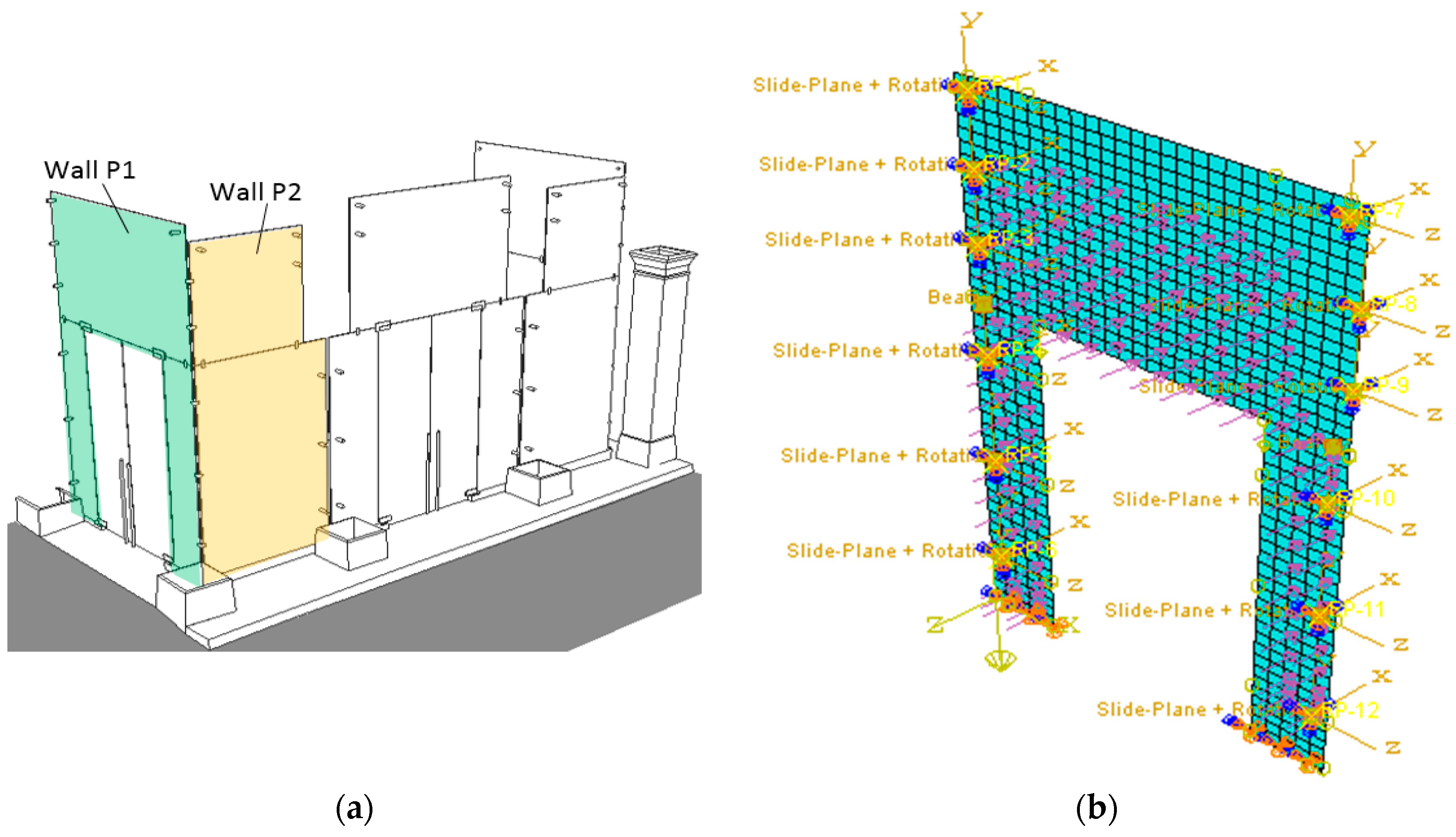
4. Case-Study Example: Glass Partition Assembly

4.1. Description of the System

The system object of analysis consists of a glass partition assembly composed of laminated glass (LG) walls with metal point-fixings. The partition assembly was designed in 2018, to take place in an historical building in Trieste (Italy), and to protect one of its entrances from wind and rain exposure (Figure 6). The building, known as “Ferdinandeo Palace” is one of the most prestigious monuments of the city (erected in 1858 in honour of the Emperor Ferdinand I of Habsburg), and since 1999 hosts the MIB School of Management.
Compared to the primary building, the glass partition object of design clearly represents a secondary system that does not affect the global resistance and stiffness of the construction (see also Figure 6b). Otherwise, the partition assembly requires careful consideration for detailing and local/global performance assessments, given the typical vulnerability and intrinsic mechanical properties of glass, as well as the class of use of the construction, the location (and the corresponding design loads) of the building and some other rigid requirements for the architectural project of the system (Section 4.2).

4.2. Reference Design Parameters, Major Requirements and Loads

Given the architectural and historical value of the building, the Palace and all the related components/interventions are under the supervision of the Superintendence for Historical Patrimony, Artistic and Ethno-Anthropological Heritage, an associated organ of the Italian Ministry for Cultural Heritage and Activities (MiBAC). For the case-study assembly, the strict request was to minimize the use of bracing components for the glass walls, thus to realize a stand-alone, fully transparent 3D partition system with a minimum number of restraints and fasteners between the glass components and the Palace (Figure 7). The partition assembly was also required to be strictly reversible and removable, without any kind of permanent damage for the historical building, once eventually dismantled.
From a structural point of view, the glass partition system is part of the Ferdinandeo building, whose constructional parameters must be properly satisfied. For the examined structure, but also in general terms, glass designers are required to size and verify a given glazed construction based on the conventional design actions for buildings that are established by national standards [9]. According to [10], the primary construction falls in fact in a Class of use III (i.e., relevant buildings with possible overcrowding), with VN ≥ 50 years. From the building entrance shown in Figure 6, moreover, up to 5–10 officers can regularly access and exit the Palace (CAT. B1 destination, corresponding to offices not accessible to public [10]). The same building entrance, finally, is also recognized to act as one of the emergency exits for the Ferdinandeo Palace, thus requiring the glass walls to properly withstand the most unfavourable design combination of loads, even under exceptional service conditions. In terms of crowd, such a detail can be conventionally accounted in the form of an accidental action given by the most unfavourable among (i) a distributed pressure Qk,crowd = 2 kN/m2, (ii) a linear horizontal load (1.20 m above the walking surface, with Hk,crowd = 1kN/m), or (iii) a concentrated load (Pk,crowd = 2 kN, over a 50 mm × 50 mm area). In non-seismic conditions (see also Equation (6)), however, crowd effects must be combined with other relevant accidental actions. For Trieste region, the reference design wind velocity at sea level is certainly of interest, being in the order of 30 m/s. This parameter turns out in fact in a characteristic wind pressure on the glass walls up to Qk,wind = 1 kN/m2. The non-seismic combination of crowd and wind actions takes advantage—for the case-study partition—of the structural configuration of the system. In the worst condition, the glass walls are in fact expected to withstand an external wind pressure that is superimposed to an internal crowd action (emergency exit). In any case, given a series of conditions to satisfy, it is clear that the design of even simple glass walls requires a multi-stage analysis.
The analysis and design of glass walls and metal connectors under seismic events must be then carried out both at the local (i.e., independent glass panels) and global levels (i.e., possible mutual interaction of walls, or between the partition assembly and the Ferdinandeo Palace), to satisfy resistance and deformation demands. Additional relevant structural verifications to assess with dedicated methods (omitted in this research paper) could be then related to the buckling resistance of the glass assembly under in-plane shear loads, or unfavourable multiple actions, whose effects could be even magnified due to the presence of non-ideal boundary conditions [36,37,38].

4.3. Design Strategy

In order to overcome the input requirements from Section 4.2 and satisfy some further client requests, the final choice of the architectural/ structural design process resulted in the erection of a series of LG panels with several typologies of metal point-fixings.
In Figure 8a, the 3D assembly is shown in its final configuration, covering up to ≈50 square meters with glass. The resisting section of each LG panel, see Figure 8b, was composed of two, 6 mm thick fully tempered layers and a 1.52 mm thick, Polyvinyl Butyral (PVB®) foil.
Globally, the constructed system involves five main glass walls, with a nominal span in the range from 1.68 m to 2.65 m. For these walls, the top height (in the range 4.3–4.65 m) is obtained by means of two glass panels in the elevation of the structure. Each glass wall is in fact obtained from the mechanical interaction of two or three LG panels, with variable size and restraint configurations. Two movable glass doors are also part of the 3D assembly (Figure 8c).
At the preliminary design stage, special care was spent for preventing the glass panels from premature fracture that could derive from their interaction with the Palace, as well as with the adjacent/orthogonal glass walls (depending on the restraints in use). Moreover, the design of LG panels was aimed at optimizing the local and global performance of the partition system, with respect to the assigned combination of design loads. In doing so, the key design concepts of robustness and redundancy were taken into account [3,4]. While each independent LG plate was intended to partly interact with the adjacent/overlying glass panels and the primary building, careful consideration was paid for the choice (type, number, position) of restraints. Even in case of accidental fracture of one of the LG panels, more in detail, the restraints were designed so as to ensure a redistribution of stresses in the adjacent elements, without the risk of premature collapse.
Basically, the bottom LG panels were designed in the form of wide side plates, with a linear, flexible clamp restraint at the base and a series of point fixings in the elevation of the partition system. In this manner, the glass structure was designed so that dead loads could be only partly sustained by the metal fixings in elevation for the 3D assembly, with a large amount directly transferred to the base foundation system. The main advantage of such a design assumption was that stress peaks in the region of elevation fixings could be minimized, thus metal joints would be mainly required to brace the LG walls against horizontal loads.
For the foundational support, bespoke stone rails were used, so as to minimize the visual impact of the partition system, with respect to the Ferdinandeo Palace (see Figure 9). These rails were properly designed in order to ensure a stable foundation system for each LG wall, with respect to out-of-plane loads, but at the same time to accommodate in-plane displacements and avoid stress peaks in glass.
The production of the stone rails required huge efforts, to accommodate the actual geometry of the Palace foundation (i.e., with irregular slopes and other local geometrical defects). At the final stage of the installation procedure, all the LG plates were thus allocated in 40 mm deep slots. Non-structural silicone sealant joints (Mapesil GP type from Mapei® [39]) and a soft gasket layer consisting of rigid Polyvinyl Chloride (PVC) provided by Metalglas® [40]—EPVC = 3.4 GPa its nominal modulus of elasticity—were introduced along each LG plate, to avoid direct contact between glass and metal components, while Hilti® [41] connectors (HST3-R type, M12 × 145 mm) provided a rigid link between the stone rails and the Palace foundation.
A set of metal connectors was then used to erect the partition walls and provide an appropriate restraint to each LG panels, in the elevation of the system. Several types of point-fixings were used, all of them composed of AISI 304 (EN 1.4301) and AISI 316 (EN 1.4436) steel types [42]. A schematic distribution of these connectors is shown in Figure 8c. Disregarding the features of these point-fixings, PVC layers (1 mm their thickness) were interposed to metal and glass components, thus avoiding potential risks due to possible stress peaks. Careful consideration was thus required for the overall installation phase, to ensure a perfect positioning and alignment of all the structural components.
Some of the steel point-fixings in use (see Figure 8c and Figure 10a,b) were realized in the form of bespoke joints able to fix the LG panels to the columns of the Palace. These bespoke joints—agreeing with and adapted from DP-44-100 devices from Metalglas®—consisted of a central M12 bolt and a steel solid section (with 42 mm the nominal diameter) for the main body and head. The total length of these devices (up to 180 mm) was properly defined for each one of them, in order to accommodate the actual distance between the partition walls and the columns of the building. A series of holes (with a diameter of 22 mm) was also realized in the resisting section of the LG panels, to facilitate the installation of the partition system but also to ensure the presence of an appropriate gap with the M12 bolts, thus preventing the occurrence of relevant stress peaks in glass due to the imposed out-of-plane or in-plane design loads.
In some other cases—i.e., in the region of the partition corners (see Figure 8c and Figure 10c)—steel friction clamps were used to link together two adjacent LG panels, without any connection with the building (V-083-90N type, Metalglas®). A similar concept was considered for the glass plates overlapping in the elevation of the system, that were connected via V-083-180N joints (Metalglas®, see Figure 10d) consisting in planar friction clamps kept together by two M10 bolts. In doing so, the installation of the overall 3D system was carried out assuming a certain gap between adjacent/overlapping/orthogonal glass plates (detail of Figure 10a, etc.). Such a choice—disregarding possible sealant joints along the LG edges—was preferred to prevent possible local interactions that could manifest in additional stress/displacement demands for the glass panels, thus ensuring a mostly independent structural response of each wall, but at the same time (thanks to the point-fixings in use) accommodating the deformations of the system as a whole 3D structural assembly.

4.4. Seismic Analysis—Out-of-Plane Performance Assessment

The local seismic analysis for each LG wall was carried out in accordance with the CNR recommendations, assuming that qa = 1 and S = 1.2 in Equations (3) and (4), and accounting that Wa ≈ 250 Kg for the glass panel of Figure 8 with maximum dimensions.
Given the peak accelerations summarized in Table 6 for each Limit State of interest (i.e., with ground type B, and T2 category of soil [10]), a maximum seismic force Fa was hence taken into account for the separate local analyses. Such a series of calculated Fa values resulted—for out-of-plane verifications—in equivalent uniform pressures Qa according with Table 6. Within a general design process, the force and pressure values reported in the Table should be then further amplified by accounting for the Ra magnifying coefficient of Equation (5), see also Figure 5a. In this study, given the small Z/H ratio of the examined system, it is reasonably assumed that Ra = 1. Such an assumption is compensated by the use of qa = 1, in place of more detailed estimates that would require detailed investigations.
In order to properly estimate the stress and displacement demand of the design seismic loads on the glass partition system, Finite Element (FE) numerical simulations were carried out in ABAQUS/Standard [43], based on separate FE models representative of each LG wall (i.e., Figure 11a). A series of static analyses was in fact carried out, taking advantage of FE models according with Figure 11b. The nominal geometry of each LG component was thus reproduced in ABAQUS, based on the available technical drawings. In doing so, the exception was represented by glass doors, that were taken into account via equivalent nodal loads (i.e., vertical forces reproducing the self-weight of door components) for the adjacent LG panels.
The use of multilayer, composite shell elements of ABAQUS library was privileged, in this study, to save the computational cost of the simulations (i.e., shell-based FE modelling), but at the same time to allow describing the nominal cross-section of the examined LG members, thus accounting for the separate glass/PVB layers of Figure 8b. Among many other simplified approaches of literature for LG members, i.e., the well-known equivalent thickness formulations for simple boundary conditions and loading distributions (see for example [44,45]), composite shell elements were also suggested by the presence in the 3D assembly of different typologies of restraints, with unsymmetrical/irregular distribution.
Regarding the characterization of materials, given that the goal of the current design process was to prevent any kind of damage in the LG components, the use of simple mechanical models was also preferred to numerically complex damage formulations for glass structures (see for example [1]). Both glass and PVB were in fact described via linear elastic constitutive laws, with nominal properties from literature [1,9,46]. For glass, the modulus of elasticity, Poisson’ ratio and density were set equal to Eg = 70 GPa, νg = 0.23 and ρg = 2500 kg/m3 respectively. In the case of PVB, equivalent input parameters accounting for the viscoelastic behaviour of material were used, with a secant shear modulus GPVB given as a function of a conventional time loading (tL) and temperature (TL) for the design action of interest (see Table 7 and [3,4,9]), with νPVB = 0.49 and ρPVB = 1100 kg/m3.
Special care was finally spent for the mechanical description of the metal connectors and the base foundation system, due to their key role for stress and displacement predictions. The FE modelling strategy was characterized by the lack of physical holes in the LG plates. Otherwise, careful consideration was paid for the accurate analysis of these critical regions. Based on the joints in use (i.e., Figure 8c), a series of kinematic constraints and connector sections was in fact defined, so as to reproduce their actual mechanical behaviour and restraint effect for the involved portions of glass. More in detail, the point-fixings of Figure 10a,b were described in the form of a set of slide plane + rotation connectors, according with Figure 12 and reproducing their mechanical effect for the LG panels under out-of-plane or in-plane loads respectively. For the out-of-plane behaviour, a rigid translational joint was used to describe the longitudinal/axial stiffness of each steel point-fixing. Rigid rotational restraints were also considered, so as to enable possible relative rotations of the LG panel, in the contact region with the steel head/body (and PVC layer interposed). The mechanical interaction of such a nodal rigid connector with the LG region of interest was then ensured by a coupling constraint between the joint and the adjacent shell elements (see Figure 12a). At the same time, the in-plane interaction of point-fixings with glass was described according to Figure 12b. The difference was represented by the translational constraint, i.e., allowing a small accommodation of displacements in glass holes and including the presence of gaps between each M12 steel bolt and the LG hole (frictionless sliding). To this aim, a final stop was used, so as to take into account the physical contact between the steel connector (with interposed PVC gasket layer) and the LG section. Given the nominal geometry and mechanical properties of the examined point-fixings, as well as the lack of more accurate experimental calibrations at the material and component level, a fully rigid in-plane stiffness was considered. In doing so, the unilateral behaviour of joints was also preserved, i.e., accounting for the possible steel-glass contact in the compression region only, but preventing any kind of tensile stress and allowing for the physical separation of the M12 bolt from glass in tension.
The FE mechanical description of friction clamps reported in Figure 10c,d was carried out on the base of similar modelling assumptions. The major difference was represented by the lack of gaps/holes, and a rigid-plastic, penalty frictional mechanism for the in-plane performance characterization. Finally, the base restraints of Figure 9 were numerically implemented in the form of a series of equivalent springs at the base edge of each LG panels of interest. In this latter case, given the flexibility of sealant joints in Figure 9a, a partial rotational restraint was taken into account for them, against out-of-plane deformations of the LG walls. At the same time, in-plane deformations of the involved LG panels were kept unrestrained (frictionless sliding).

4.5. Seismic Analysis—In-Plane Performance Assessment

Due to in-plane seismic forces, stress and displacement demands were verified with the support of additional FE simulations, following the same numerical procedure summarized in Section 4.4. In the latter case, however, multiple seismic effects were properly taken into account for the analyses, being represented by:
(1)
the in-plane seismic force Fa that the independent glass panel must withstand, based on Equation (3), see Table 6, and
(2)
the additional series of in-plane seismic forces RQ deriving (when present) by orthogonal LG walls, being transferred by the frictional clamps.
In Figure 13, for example, evidence is given to the local reaction forces RQ that the P1 wall under out-of-plane pressure can transfer to the orthogonal P2 wall.

4.6. Seismic Verification of the Glass Partition System
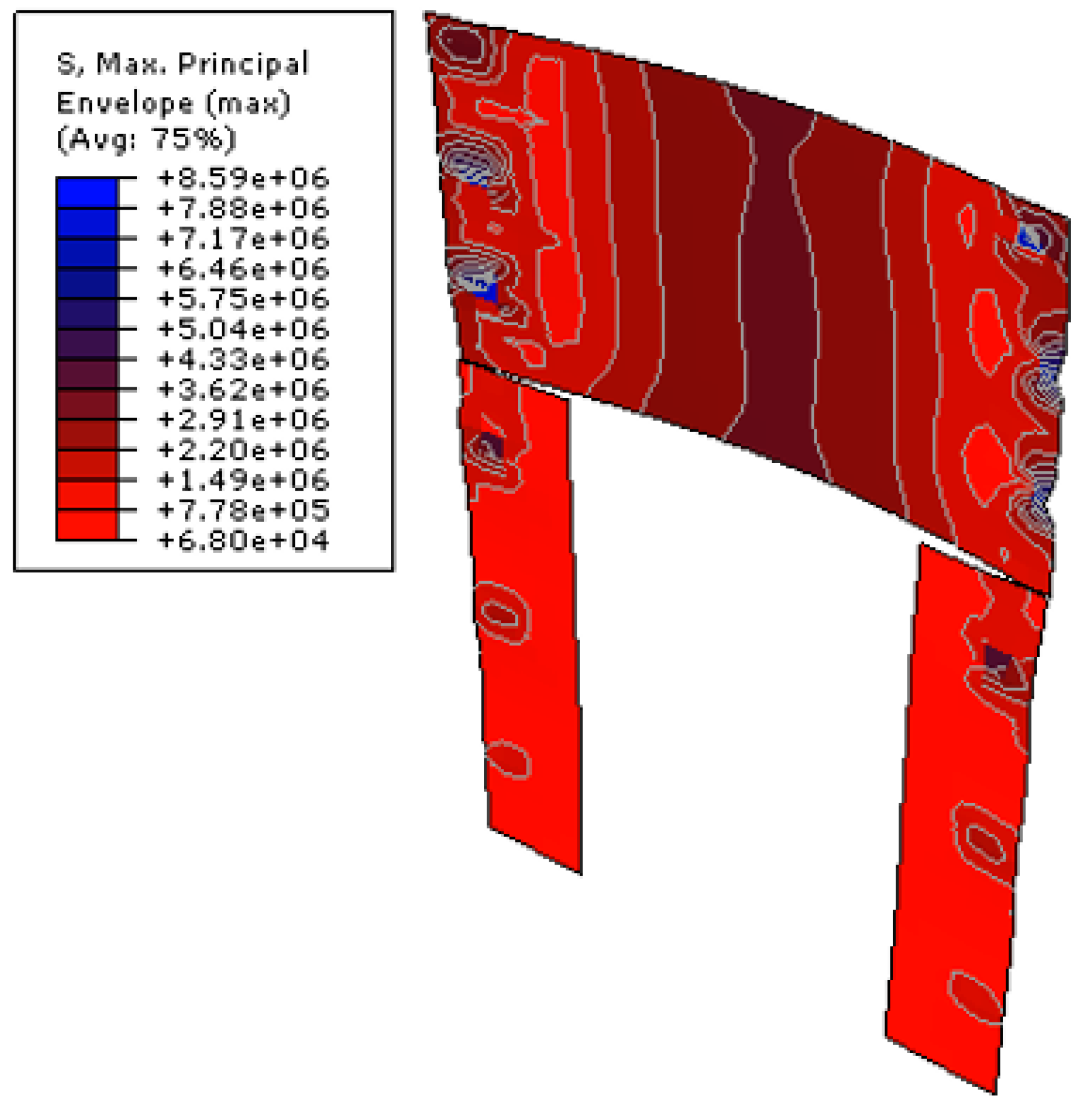
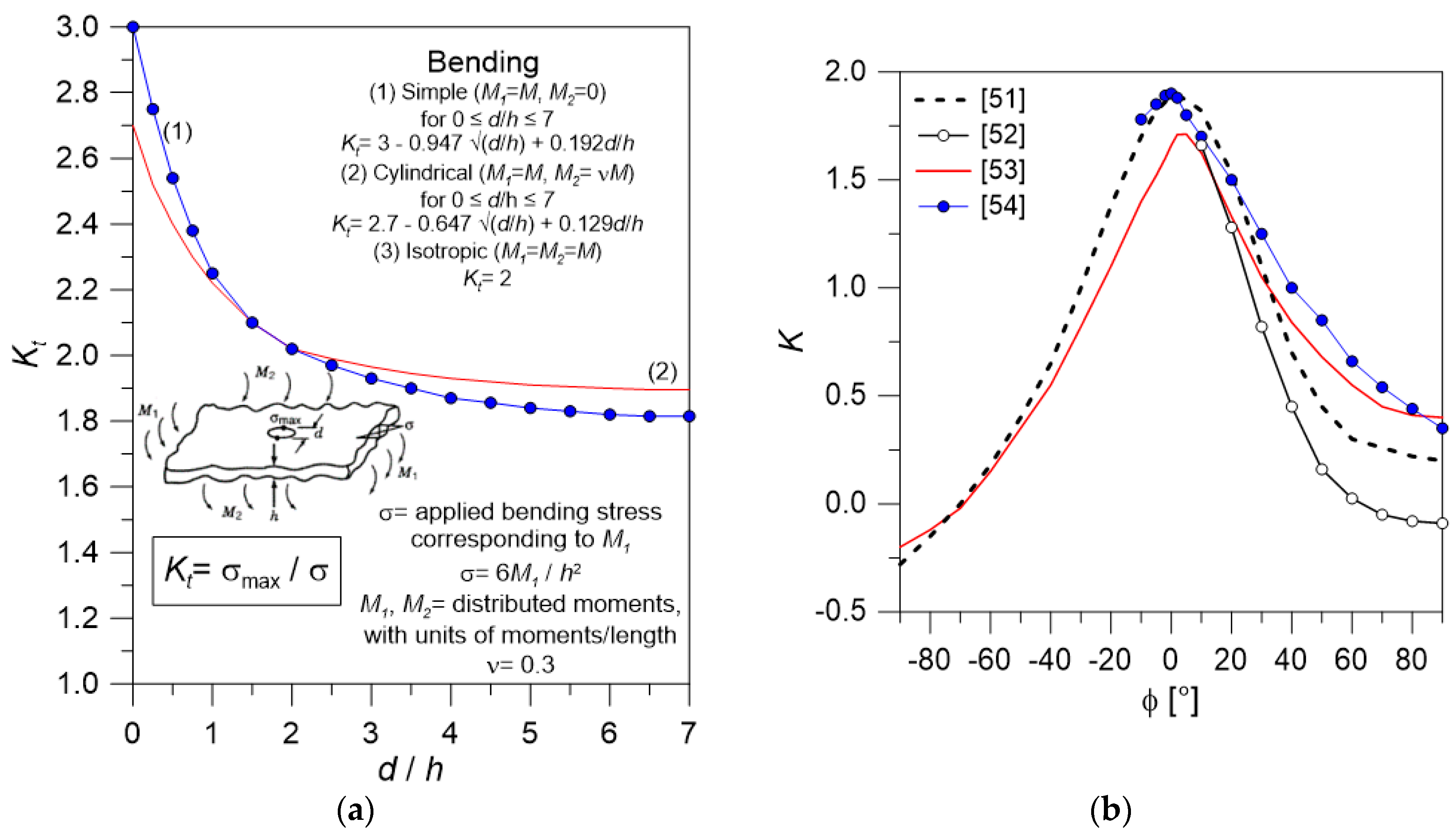
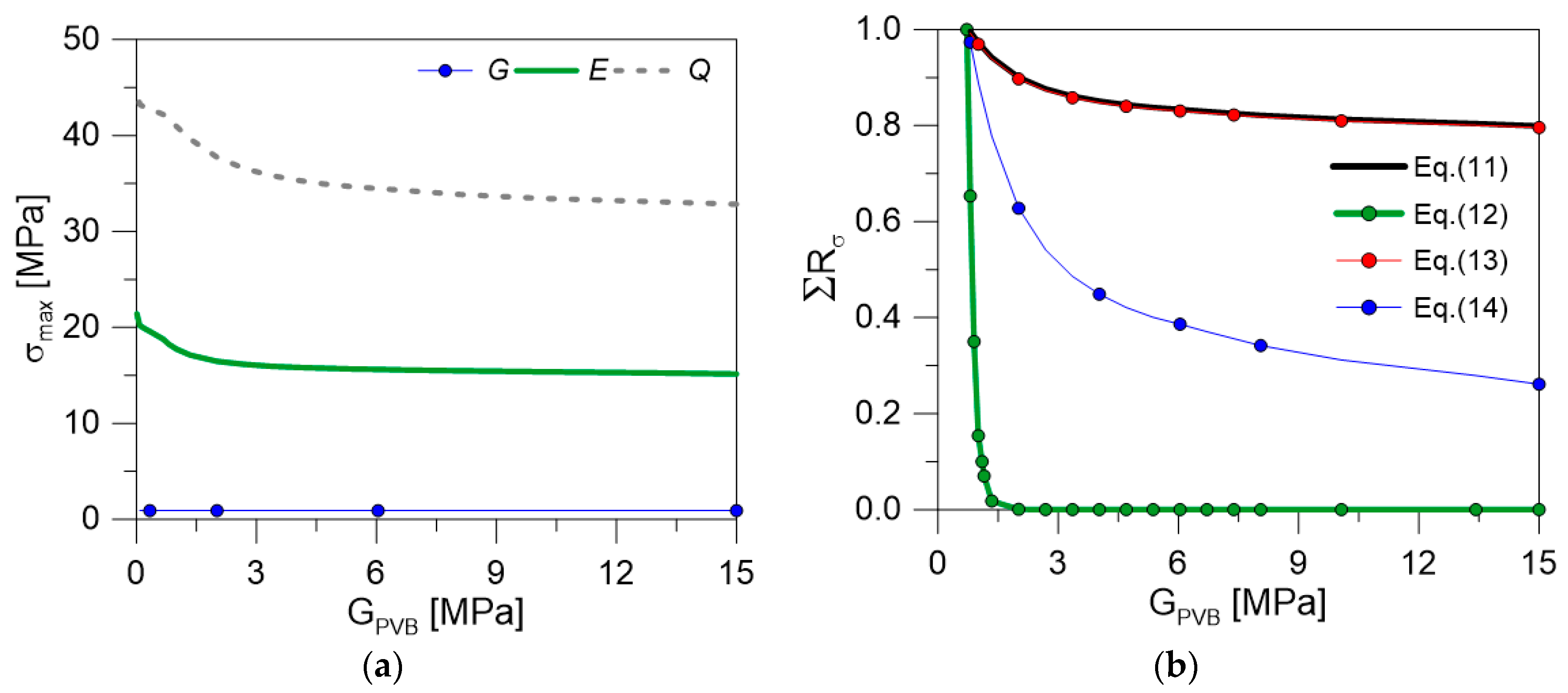
The goal of the seismic analysis for the glass partition walls is to assess that maximum stresses in glass do not exceed the material resistance at the Limit States of interest, and that the system is able to accommodate the required displacements. As known, the seismic combination of loads requires that the system is analyzed under the effects of simultaneous dead (G), seismic (E) and accidental loads (Qkj), that is:
F d , E = G + E + j Ψ 2 j Q k j
with Ψ2j = 0 for wind and Ψ2j = 0.3 for CAT. B1 offices. For the case-study system discussed herein, see Table 6, Equation (6) turns out in dead loads that are expected to have negligible stress and displacement effects in glass, as well as seismic forces that are sensitively lower than the combined crowd pressure (with Q = 0.3 × 2 = 0.6 kN/m2 the reference design value in seismic conditions). Otherwise, the structural behaviour of the independent LG panels and the full 3D assembly must be analyzed in detail, including direct or indirect out-of-plane and in-plane loading contributions.
As far as Equation (6) includes multiple design actions having specific features (i.e., magnitude, distribution, characteristic duration tL, conventional temperature TL), different demands are expected from each one of them. At the same time, a different mechanical contribution is expected from the PVB foils in use, thus from the assembled LG sections, given that both tL and TL can affect the shear modulus GPVB [3,4,9].
When more detailed estimates and material properties are not available (especially experimental tests, given that PVB properties can modify depending on the manufacturer), the conservative values recommended in Table 7 can be taken into account for design. Special care should be spent for the characterization of “duration” for short-term/high intensity design actions like an input seismic event. Besides the intrinsic complexity of, the typical peak duration tL for engineering applications is expected in the range of ≈5 s [47,48,49], but can be conservatively set as for “transient” loads (§4.10 [9]), hence disregarding the enhanced stiffness of PVB layers under impact. From a practical point of view, it is in any case convenient to estimate maximum stresses and displacements in the LG elements based on separate FE analyses, and then properly combine the maximum effects.

4.6.1. Resistance

The design tensile strength of glass under bending is conventionally given by (§7.4 [9]):
f g ; d = f g ; d , b + f g ; d , p = k mod k e d k s f λ g A λ g l f g ; k R M γ M + k e d k v ( f b : k f g ; k ) R M ; v γ M ; v
with fg;d,p > 0 for pre-stressed glass, and the resistance verification requires that the stress effects of a given design action do not exceed the capacity of the system, that is:
σ max f g ; d .
The coefficients of Equation (7) are fully described in the CNR document, and basically reflect the type of treatment and the features of glass, the shape of the panel to verify, etc. Among them, a relevant parameter is represented by kmod, being representative of static fatigue effects and depending on the loading time tL (in hours). Given the reference values of Table 7 that must be separately taken in Equation (6), kmod can be estimated as (§2.1.1.2 [9]):
k mod = 0.585 · t L 1 / 16 .
Based on the typology and destination of the case-study partition system, in this paper it is first verified that glass does not fracture during SLC seismic events (i.e., design actions of Table 6). For fully tempered LG panels agreeing with Figure 11, the “near edges” stress verification in the region of holes reflects in a design resistance fg;d ≈ 61.5 MPa against transient seismic loads (kmod = 0.78).
In Figure 14, a typical example of stress distributions is proposed for the P1 wall under out-of-plane seismic pressure (SLC). Besides the negligible magnitude of predicted tensile stress peaks (up to σFE ≈ 8.6 MPa) and their concentration in a limited portion of glass (i.e., region of point-fixings), a special care is required for the stress verification close to holes and edges, where the actual limit condition to satisfy is given by:
σ max = σ FE K f g ; d
and K is a stress concentration factor.
In the case of monolithic plates in simple bending (thickness h), K = Kt follows Figure 15a. For LG plates as in the examined system (with a hole diameter-to-glass thickness ratio equal to d/h ≈ 1.83), Figure 15a turns out in K ≈ 2.05. Besides the availability of several literature proposals to account for the stress concentration in the region of holes (i.e., [3,4,50]), in this context, it is important to notice that the typical structural glass applications involve relatively small d/h values. At the same time, see Figure 15a, the minimum recommended value for K is in any case ≈ 1.8, thus requiring an appropriate thickness for glass members object of design. Minor variations can be expected in the reference d/h values (thus K) for LG plates, given that GPVB (or others) modifies with the loading configuration (i.e., Table 7), and thus different equivalent, monolithic glass thicknesses h should be used to account for the actual out-of-plane bending stiffness associated to each design action.
Similar considerations must be then taken into account for glass panels under in-plane loads (i.e., dead and seismic loads, in this study), with expected amplification factors in the order of ≈1.9 times the calculated σFE value (see Figure 15b, with ϕ = 0°, and [51,52,53,54]). In the latter case, however, the presence of gaps (i.e., Figure 12) can strongly minimize possible stress peaks. The use of additional soft interposed layers and gaskets (i.e., aluminum or rubber, or even PVC, as in this case-study) can be further beneficial for the critical region of edges [3,4].
Depending on the restraint and loading configuration, compressive stress peaks in glass should be also prevented. With respect to Equation (7), the theoretical compressive strength of soda-lime glass is however in the order of fc;k = 1000 MPa and for practical purposes—when experimental feedback is not available—could be limited to ≈350–500 MPa [55,56,57].
A final attention is then given to the seismic combination of design actions. According to [9], the reference limit condition for the resistance verification of a given control point against the SLC loading combination of Equation (6) is in fact given by:
i = 1 n R σ i = i = 1 n σ max i f g ; d i 1
where fg;d for the ith action is estimated in Equation (7) based on the corresponding kmod coefficient. Among many others [58,59,60,61], the Palmgren-Miner based, linear cumulative damage approach of Equation (11) is recommended by the CNR guide as a practical tool to account for static fatigue effects in glass, in place of theoretically exact but even complex formulations. The design issue, however, still requires extended investigations and represents an open question for the research community. With respect to the exponential model proposed by Franco & Royer in [59], that is:
i = 1 n [ ( i = 1 n σ i ) σ p + ] m [ ( i = 1 n 1 σ i ) σ p + ] m ( f g d , b ) i m 1
(with m = 16 and σp = fg;d,p in Equation (7)).
It was in fact shown in [60] that Equation (11) can be conservative—depending on the combined design actions—especially for annealed glass members, with a minimum 25% scatter (and even up to 50–60%) of the expected cumulative damage. Otherwise, for pre-stressed elements of primary use for structural applications, the CNR approach can offer reliable predictions.
Certainly, Equation (11) represents a more accurate tool, with respect to the simplified and strongly approximate pr-EN formulation [61]:
i = 1 n σ max i max ( f g ; d i ) 1 .
As also discussed in [60], moreover, the intrinsic advantage of linear cumulative approaches can be preserved—with minimized approximations—thanks to the “weighted average” (WA) formulation, that is
i = 1 n σ i f g d * 1
with f*gd still given by Equation (7), but introducing a “weighted” kmod,w coefficient:
k mod = k mod , w = i = 1 n σ i k mod , i i = 1 n σ i
and:
σ i = ( i = 1 n σ i ) max ( ( i = 1 n 1 σ i ) , σ p ) 0
(with σp = fg;d,p in Equation(7))
In this study, given that kmod = 0.26 for dead loads (tL = 50 years, Table 7) and kmod = 0.78 for crowd (tL = 30 s), the corresponding fg;d values can be estimated from Equation (7) in ≈ 50 MPa and ≈ 61.5 MPa, respectively. Consequently, Equation (11) reflects in a LG structure that is able to properly withstand the imposed SLC seismic combination of Equation (6). Detailed comparative examples are proposed in Table 8 for the P1 wall under out-of-plane seismic pressure, giving evidence of the verification outcomes for all the mentioned approaches.
However, see Table 8, different calculation assumptions for Equations (11)–(14) turn out in sensitive variations for the cumulative damage predictions, thus can affect the overall design process. As far as the total stress ratio Rσ is taken into account in Equation (11) for the ith design action of interest, for example, it can be seen in Figure 16a that the resistance demand due to the out-of-plane seismic pressure (E) is limited, with respect to the crowd accidental load (Q), while dead load effects (G) can be generally disregarded. Given that the stress verification is conservatively carried out with the reference tL, TL and GPVB input parameters from Table 7, a positive SLC check can be obtained (see also Figure 16b).
From the same figures it can be seen that even small variations in the shear stiffness GPVB of the bonding foils (i.e., due to possible material degradation due to severe operational or ambient conditions, see also [62,63]) are expected to manifest in sensitive variations of predicted stresses, thus even in potential premature failure. As also previously discussed for Equation (6) and Table 7, careful consideration is also required for the tL characterization of seismic events (and thus GPVB assumptions), given that the dynamic response and shear stiffness of PVB foils is strongly sensitive to the vibration frequency, but also to testing procedures, thus requiring more sophisticated calculation methods (see for example [64,65,66]).
Another relevant aspect, see Figure 16b, is associated to the combination of cumulative stress effects, for the design actions of interest. As also discussed in [60], the intrinsic advantage of linear cumulative approaches according to Equations (11), (13) or (14) can preserve in designers a deepest awareness on detailing and design assumptions, for safe purposes. The exponential formulation proposed in [59], otherwise, is generally sensitive to minimum variations in the input material properties, thus leading to possible uncertainties in design.

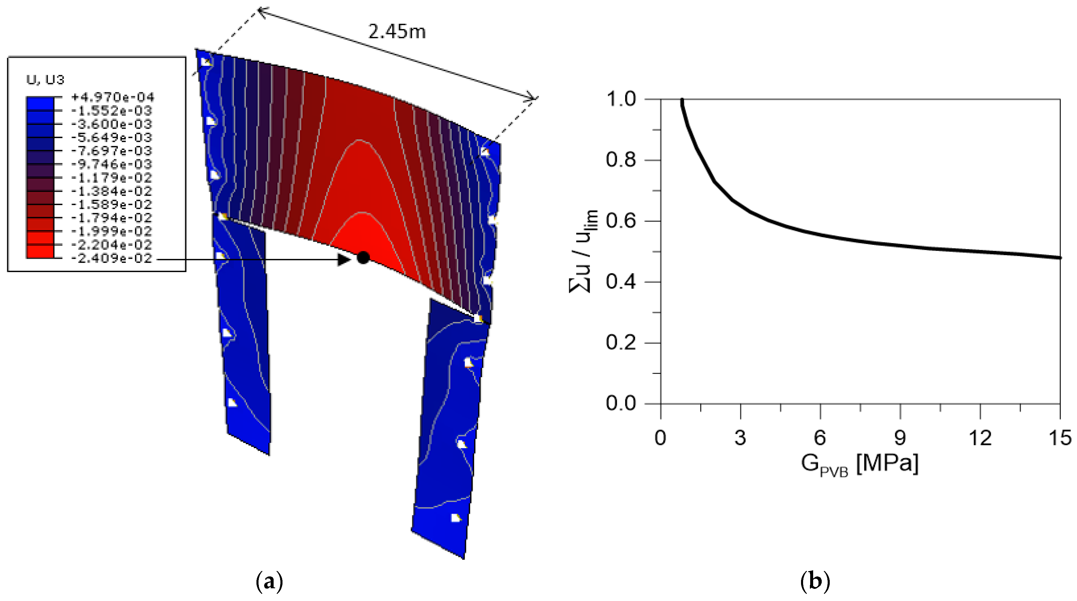
4.6.2. Displacements

Besides the resistance verification in the potential critical regions of glass walls, a key role is certainly assigned to the capacity of the glazed structure to accommodate the displacement demand of the incoming seismic events. To this aim, both the out-of-plane and in-plane flexibility of the case-study system need in fact to be separately assessed. Also, in this case, the detailing of joints and restraints can have relevant effects. In general, given the SLD load combination of Equation (6), it is required that the maximum deformation demand (Σu)—as given by the sum of displacement contributions ui due to the ith action—is able to satisfy specific limit values of deformation, both out-of-plane and in-plane. For independent LG panels with point-fixing restraints in out-of-plane bending, the CNR guide recommends that Σu does not exceed the minimum value given by (§7.5 [9]):
(a)
ulim = Linf/100, with Linf the distance between two point supports (or ulim = Linf/50, in presence of spandrels), or
(b)
ulim = 50 mm.
For the case-study system, major flexibility issues can derive from the LG panels with large dimensions (i.e., the top panel of the P1 wall). While the SLD seismic pressure is in fact expected to involve limited deformations in the LG system (i.e., due to the design pressure values reported in Table 6), maximum effects can derive from the incoming crowd load, due to the class of use and destination of the Ferdinandeo Palace. In Figure 17a, given that Linf = 2.45 m and ulim = 24.5 mm for the upper panel of the P1 wall, it can be seen that the maximum out-of-plane SLD deflection is in the order of Σu = 24.09 mm, thus able to satisfy the recommended deformation limits (i.e., with load and PVB parameters according with Table 7). As in the case of stress peaks, however, an high sensitivity of the 3D structure to operational and ambient conditions can be perceived from Figure 17b, where the total out-of-plane deformation check is proposed for the P1 wall as a function of a variable GPVB modulus.
Special attention is also required against SLD in-plane seismic effects, involving a double check of maximum deformations (and corresponding stress peaks) of the partition components. Each LG panels must in fact be verified as independent wall under the seismic forces of Table 6. At the same time, however, the LG partition as a whole must be able to accommodate the Ferdinandeo deformations and inter-storey drifts under seismic events, as a secondary structural component of the building.
In the first case (i.e., local analysis) the in-plane deformation of each LG wall can be carried out in the form of a force-controlled analysis of each FE model, by accounting for the SLD forces that the orthogonal glass walls (when present) can transfer through the point-fixings in use. An example of the typical deformed shape is proposed in Figure 18a for the P1 wall. As shown, given the limited magnitude of SLD seismic forces in Table 6, most of the required deformation demand can be satisfied by the P1 components, thanks to the beneficial contribution of gaps. The total displacement is in fact slightly exceeding 5 mm, i.e., the allowable clearance, thus resulting in negligible compressive stresses in the region of glass holes.
The same P1 wall (and others), however, must be able to accommodate the global deformation of the Ferdinandeo building. In this case, a displacement-controlled analysis is thus recommended for the glazed components and FE models according to Figure 18a.
Given the lack of more detailed data in support of design, and following the general NTC2018 provisions [10], a reference SLD drift corresponding to umax = 0.002 × H = 9.3 mm can be taken into account for the global deformation of the LG walls. The latter represents the conventional SLD drift for masonry constructions, with H = 4.65 m the total height of the 3D partition system, thus the in-plane deformation that the LG walls should be able to accommodate without damage. As far as umax is imposed to each LG wall object of study, the hole gap for the point-fixings in use gives further evidence of intrinsic benefits, allowing to minimize the global deformation demands of the system. The global deformation of the P1 wall still qualitatively agrees with Figure 18a. A more detailed analysis of the P1 wall (and others) in-plane response, however, gives evidence of (i) an initial rigid body deformation (up to 5 mm), followed by (ii) a residual drift equal to (umax—5 mm) = 4.3 mm and activating the steel-glass contact interactions. In the latter case, compressive stress peaks in glass must be thus properly verified. Given the geometrical and mechanical details of interest in this study, see Figure 18b, compressive stresses are estimated in the order of ≈ 53 MPa, thus relatively low compared to the conventional material resistance for design (see also Section 4.6.1).

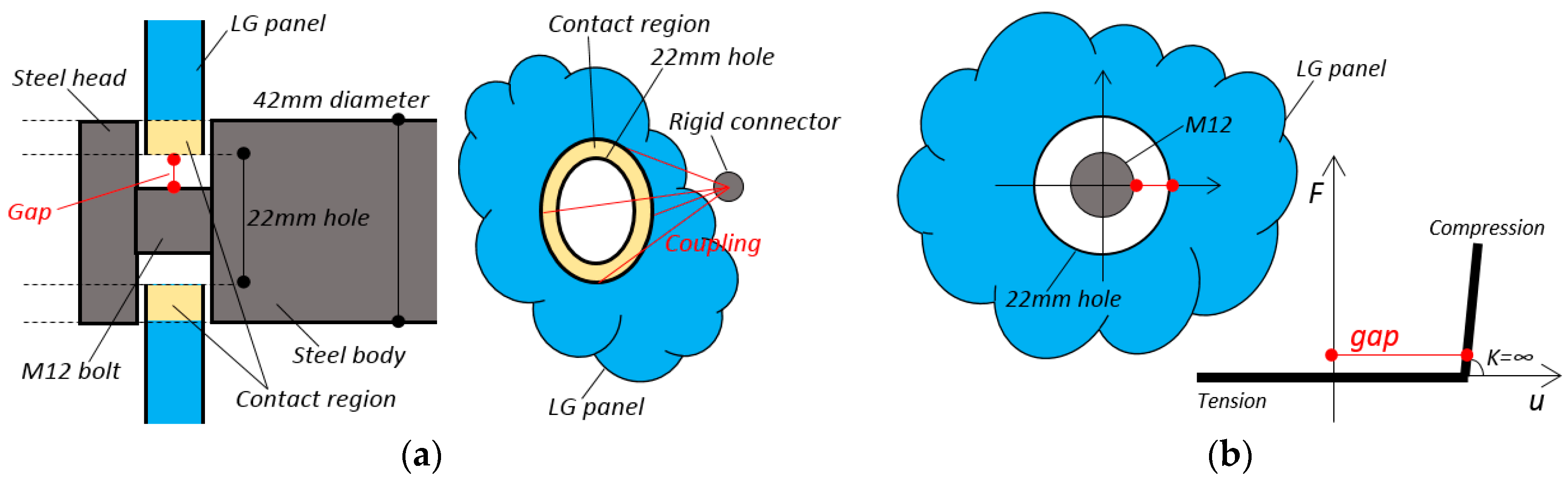
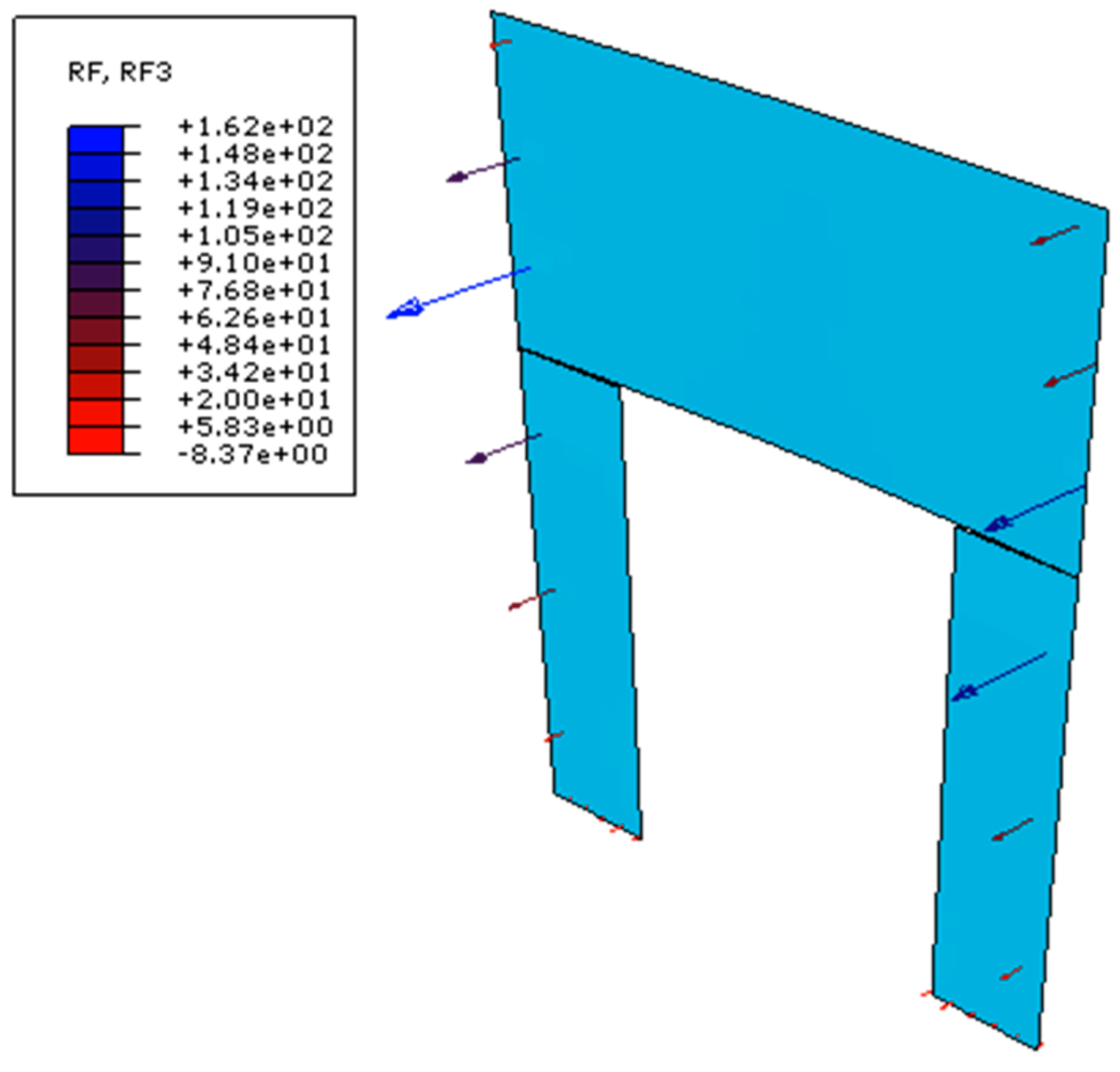
4.7. Verification of Restraints and Fasteners

At the final stage of the design process, restraints and fastening devices must be also properly verified, so that they could allow the glass elements to withstand the input seismic loads without any possible premature collapse.
For the examined system, for example, research studies were carried out to investigate the actual stress demand on the steel devices in use. Actually, the study proved that the maximum SLC shear forces that the steel devices must sustain are mostly negligible, due to the limited amount of the design seismic forces (i.e., Table 6).
Special care, however, is required also for additional relevant mechanisms that could affect the overall robustness and resistance of the structure, like for example the out-of-plane design loads acting on the partition walls. In this regard, Figure 19 shows the maximum reaction forces that the steel joints of Figure 10a are required to withstand when SLC out-of-plane seismic pressures are applied to the P1 wall.
While the potential fracture on the side of glass can be rationally verified with the support of Section 4.6.1, damage propagation and possible collapse of steel joints must be properly verified, and this can be carried out with the support of experimental tests [9,10]. For the examined case study, a relevant role is assigned to the pull-out resistance and mechanical performance of the point-fixings in use. An example is shown in Figure 20, where the tensile fracture mechanism is shown for the steel point fixings with passing M12 bolts (in use for the glass-to-column connections). The test examples herein reported is part of a series of experiments carried out at the University of Trieste, Department of Engineering and Architecture, in support of the design process [67]. While the presence of a M12 bolt section would reflect in a relatively high tensile resistance of the net surface, the tensile experiments gave evidence of a potential failure of joints in the region of head-to-bolt connection (Figure 20b). In any case, collapse was observed for a relatively high tensile load (≈59 kN the average experimental ultimate load), compared to the design reaction forces to sustain in service conditions (i.e., Figure 19) and to maximum stresses expected in the LG components (i.e., Figure 14). Otherwise, the robustness and redundancy of the overall system should be properly verified at different levels of analysis.

5. Conclusions

In this paper, the current design strategies for glass systems under seismic loads were discussed, by taking into account existing standards and guideline documents for earthquake resistant structures. A special focus was given to the existing Italian recommendations, where the CNR-DT 210/2013 guide and the national standard for buildings (NTC2018) are used, with an insight on the typology of secondary frameless glass systems.
Safe performances must be ensured for these glazed assemblies, in which metal connectors and fasteners are reduced to a minimum. The potential risks of premature fracture and collapse for a typically vulnerable material like glass is further enforced especially under extreme events, like earthquakes. However, most of the available design regulations do not provide specific recommendations to estimate the expected effects, and thus optimize the structural details.
A case-study system was hence presented in the paper, being representative of a glass partition assembly of recent construction (2018), within the framework of a historical strategic building in Trieste (Italy). Based on detailed but computationally efficient Finite Element (FE) numerical simulations, it was shown that seismic events for secondary frameless glass structures can even involve minor stress and displacement demands, with respect to other relevant design actions. However, the reliable estimate (and thus prevention) of severe stress/displacement demands requires the implementation of specific methods of analysis. Careful consideration is generally required by critical regions, like glass portions near holes, as well as the region of restraints and fasteners in general. Most of the restraints are in fact characterized by mechanical performances that are often far away from “ideal” boundary conditions of practical use in simulations, thus requiring specific modelling assumptions. At the same time, the combination of multiple design actions and the corresponding stress effects in glass must be properly assessed, given that different calculation approaches are available in the literature and could result—for a given structural system—in even major scatter for the expected cumulative damage. In conclusion, a focus is given to the capacity of secondary glass structures to accommodate the displacement demands under seismic events.

Author Contributions

This paper results from the collaboration of all the involved authors. C.B.: conceptualization, methodology, investigation; C.A. and S.N.: investigation, experiments; C.B., C.A. and S.N.: writing-original draft preparation, writing-review & editing.

Funding

This research study received no external funding. The APC for the publication of the paper was financially supported by MDPI (first author review vouchers).

Acknowledgments

Alviero Seretti (Seretti Vetroarchitetture S.r.l., www.seretti.it) and Arch. Andrea Danelutti (www.andreadanelutti.com) are gratefully acknowledged for sharing data, technical drawings and photos of the case-study glass partition system. Ing. Franco Trevisan (University of Trieste, Department of Engineering and Architecture) is also acknowledged for the technical support during the experimental tests, and for sharing test data.

Conflicts of Interest

The authors declare no conflict of interest.

References

  1. Santarsiero, M.; Bedon, C.; Moupagitsoglou, K. Energy-based considerations for the seismic design of ductile and dissipative glass frames. Soil Dyn. Earthq. Eng. 2019, 125, 105170. [Google Scholar] [CrossRef]
  2. Bedon, C.; Santarsiero, M. Transparency in structural glass systems via mechanical, adhesive, and laminated connections—Existing research and developments. Adv. Eng. Mater. 2018, 20, 1700815. [Google Scholar] [CrossRef]
  3. Haldimann, M.; Luible, A.; Overend, M. Structural Use of Glass; IABSE: Zurich, Switzerland, 2008; ISBN 978-3-85748-119-2. (CH). [Google Scholar]
  4. Feldmann, M.; Kasper, R.; Abeln, B.; Cruz, P.; Belis, J.; Beyer, J.; Colvin, J.; Ensslen, F.; Eliasova, M.; Galuppi, L.; et al. Guidance for European Structural Design of Glass Components—Support to the Implementation, Harmonization and Further Development of the Eurocodes; Dimova, S., Pinto, A.V., Feldmann, M., Denton, S., Eds.; Report EUR 26439–Joint Research Centre–Institute for the Protection and Security of the Citizen: Ispra, Italy, 2014. [Google Scholar] [CrossRef]
  5. Bedon, C.; Zhang, X.; Santos, F.; Honfi, D.; Kozlowski, M.; Arrigoni, M.; Figuli, L.; Lange, D. Performance of structural glass facades under extreme loads—Design methods, existing research, current issues and trends. Constr. Build. Mater. 2018, 163, 921–937. [Google Scholar] [CrossRef]
  6. Overend, M.; De Gaetano, S.; Haldimann, M. Diagnostic Interpretation of Glass Failure. Struct. Eng. Int. 2007, 17, 151–158. [Google Scholar] [CrossRef]
  7. Honfi, D.; Reith, A.; Vigh, L.G.; Stocker, G. Why Glass Structures Fail?—Learning from Failures of Glass Structures. In Proceedings of the Challenging Glass 4 & COST Action TU0905 Final Conference, Lausanne, Switzerland, 6–7 February 2014; pp. 791–800, ISBN 978-1-138-00164-0. [Google Scholar] [CrossRef]
  8. European Committee for Standardization. Eurocode 8: Design of Structures for Earthquake Resistance—Part 1: General Rules, Seismic Actions and Rules for Buildings; EN 1998-1:2004; CEN: Brussels, Belgium, 2014. [Google Scholar]
  9. CNR-DT 210/2013. Istruzioni per la Progettazione, L’esecuzione ed il Controllo di Costruzioni con Elementi Strutturali di vetro [Guide for the Design, Construction and Control of Buildings with Structural Glass Elements]; National Research Council of Italy (CNR): Roma, Italy, 2013; (Italian version); Available online: www.cnr.it/it/node/2630 (accessed on 1 November 2019).
  10. NTC2018. Norme Tecniche per le Costruzioni; Design Standard for Buildings; Ministero delle Infrastrutture e dei Trasporti: Roma, Italy, 17 Gennaio 2018. (In Italian)
  11. Overend, M. Recent developments in design methods for glass structures. Struct. Eng. 2010, 88, 18–26. [Google Scholar]
  12. Green, R. The Challenges of Writing a Structural Standard for Glass. In Proceedings of the Challenging Glass Conference, Ghent, Belgium, 16–17 June 2016; Volume 5, pp. 623–632. [Google Scholar] [CrossRef]
  13. Feldmann, M.; Di Biase, P. The CEN-TS “Structural Glass–Design and Construction Rules” as pre-standard for the Eurocode. In Proceedings of the Conference Engineered Transparency, Düsseldorf, Germany, 23–26 October 2018. [Google Scholar] [CrossRef]
  14. Sucuoglu, H.; Vallabhan, C.V.G. Behaviour of window glass panels during earthquakes. Eng. Struct. 1997, 19, 685–694. [Google Scholar] [CrossRef]
  15. Wensheng, L.; Baofeng, H. Discussion on Seismic Performance Indexes of Architectural Curtain Walls. In Proceedings of the 14th WCEE Conference—World Conference on Earthquake Engineering, Beijing, China, 12–17 October 2008. [Google Scholar]
  16. Sivanerupan, S.; Wilson, J.L.; Gad, E.F. Structural analysis and design of glazed curtain wall systems. Aust. J. Struct. Eng. 2011, 12, 57–67. [Google Scholar]
  17. Overend, M.; Nhamoinesu, S.; Watson, J. Structural Performance of Bolted Connections and Adhesively Bonded Joints in Glass Structures. J. Struct. Eng. 2013, 139, 04013015. [Google Scholar] [CrossRef]
  18. Bernard, F.; Daudeville, L. Point fixings in annealed and tempered glass structures: Modeling and optimization of bolted connections. Eng. Struct. 2009, 31, 946–955. [Google Scholar] [CrossRef]
  19. Nielsen, J.H.; Olesen, J.F.; Poulsen, P.N.; Stang, H. Simulation of residual stresses at holes in tempered glass: A parametric study. Mater. Struct. 2010, 43, 947–961. [Google Scholar] [CrossRef]
  20. Katsivalis, I.; Thomsen, O.T.; Feih, S.; Achintha, M. Strength evaluation and failure prediction of bolted and adhesive glass/steel joints. Glass Struct. Eng. 2018, 3, 183–196. [Google Scholar] [CrossRef] [Green Version]
  21. Amadio, C.; De Luca, O.; Fedrigo, C.; Fragiacomo, M.; Sandri, C. Experimental and numerical analysis of glass-to-steel joint. J. Struct. Eng. 2008, 134, 1389–1397. [Google Scholar] [CrossRef]
  22. Martins, L.; Delgado, R. Seismic Behavior of Point Supported Glass Panels. In Proceedings of the Challenging Glass 3—Conference on Architectural and Structural Applications of Glass, TU Delft, Delft, The Netherlands, 28–29 June 2012. [Google Scholar]
  23. Sivanerupan, S.; Wilson, J.L.; Gad, E.F.; Lam, N.T.K. Drift performance of point fixed glass façade systems. Adv. Struct. Eng. 2014, 17, 1481–1495. [Google Scholar] [CrossRef]
  24. Casagrande, L.; Bonati, A.; Occhiuzzi, A.; Caterino, N.; Auricchio, F. Numerical investigation on the seismic dissipation of glazed curtain wall equipped on high-rise buildings. Eng. Struct. 2019, 179, 225–245. [Google Scholar] [CrossRef]
  25. Aiello, C.; Caterino, N.; Maddaloni, G.; Bonati, A.; Franco, A.; Occhiuzzi, A. Experimental and numerical investigation of cyclic response of a glass curtain wall for seismic performance assessment. Constr. Build. Mater. 2018, 187, 596–609. [Google Scholar] [CrossRef]
  26. Krstevska, L.; Tashkov, L.; Rajcic, V.; Zarnic, R. Seismic behaviour of composite panel composed of laminated wood and bearing glass—Experimental investigation. Adv. Mater. Res. 2013, 778, 698–705. [Google Scholar] [CrossRef]
  27. Stepinac, M.; Rajcic, V.; Zarnic, R. Timber-structural glass composite systems in earthquake environment. Gradevinar 2016, 68, 211–219. [Google Scholar]
  28. Bedon, C.; Amadio, C. Numerical assessment of vibration control systems for multi-hazard design and mitigation of glass curtain walls. J. Build. Eng. 2018, 15, 1–13. [Google Scholar] [CrossRef] [Green Version]
  29. Bedon, C.; Amadio, C. Enhancement of the seismic performance of multi-storey buildings by means of dissipative glazing curtain walls. Eng. Struct. 2017, 152, 320–334. [Google Scholar] [CrossRef] [Green Version]
  30. Desai, P.; Golmohammadi, A.; Garlipp, R.; Gowda, B. New Point Supported Glass Seismic System. In Proceedings of the AESE 2005–First International Conference on Advances in Experimental Structural Engineering, Nagoya, Japan, 19–21 July 2005; p. 8. [Google Scholar]
  31. March, M. Structural glass columns in significant seismic zones. In Proceedings of the GlassCon Global 2014, Pennsylvania Convention Center, PA, USA, 7–10 July 2014; pp. 470–486. Available online: http://www.glassconglobal.com/pdfs/GlassCon-Global-2014-Proceedings-Book.pdf (accessed on 1 November 2019).
  32. European Committee for Standardization. Basis of Structural Design; EN 1990:2002; CEN: Brussels, Belgium, 2002. [Google Scholar]
  33. Bedon, C.; Fasan, M.; Amadio, C. Vibration analysis and dynamic characterization of structural glass elements with different restraints based on Operational Modal Analysis. Buildings 2019, 9, 13. [Google Scholar] [CrossRef]
  34. Lenci, S.; Consolini, L.; Clementi, F. On the experimental determination of dynamical properties of laminated glass. Ann. Solid Struct. Mech. 2015, 7, 27–43. [Google Scholar] [CrossRef]
  35. Zemanova, A.; Zeman, J.; Janda, T.; Schmidt, J.; Sejnoha, M. On modal analysis of laminated glass: Usability of simplified methods and Enhanced Effective Thickness. Compos. Part B Eng. 2018, 151, 92–105. [Google Scholar] [CrossRef] [Green Version]
  36. Bedon, C.; Amadio, C. Buckling of flat laminated glass panels under in-plane compression or shear. Eng. Struct. 2012, 36, 185–197. [Google Scholar] [CrossRef]
  37. Bedon, C.; Amadio, C. Shear glass panels with point-fixed mechanical connections: Finite-Element numerical investigation and buckling design recommendations. Eng. Struct. 2016, 112, 233–244. [Google Scholar] [CrossRef]
  38. Bedon, C.; Amadio, C. A unified approach for the shear buckling design of structural glass walls with non-ideal restraints. Am. J. Eng. Appl. Sci. 2016, 9, 64–78. [Google Scholar] [CrossRef]
  39. Mapei®. Technical Data Sheet and Catalogue for Silicone Sealants. Available online: www.mapei.com (accessed on 1 November 2019).
  40. Metalglas®. Technical Data Sheet for Mapesil GP Silicone. Available online: www.metalglas.it (accessed on 1 November 2019).
  41. Hilti®. Technical Data Sheet for HST3-R Expansion Anchor. Available online: www.hilti.it (accessed on 1 November 2019).
  42. European Committee for Standardization. Stainless Steels—Part 1: List of Stainless Steels; EN 10088-1: 2014; CEN: Brussels, Belgium, 2014. [Google Scholar]
  43. Simulia. ABAQUS Computer Software; Dassault Systemes Simulia Corporation: Johnston, RI, USA, 2019. [Google Scholar]
  44. Calderone, I.; Davies, P.S.; Bennison, S.J.; Huang, X.; Gang, L. Effective Laminate Thickness for the Design of Laminated Glass. In Proceedings of the Glass Performance Days, Tampere, Finland, 12–15 June 2009. [Google Scholar]
  45. Galuppi, L.; Royer-Carfagni, G.F. Effective thickness of laminated glass beams: New expression via a variational approach. Eng. Struct. 2012, 38, 53–67. [Google Scholar] [CrossRef]
  46. European Committee for Standardization. Glass in Buildings-Basic Soda Lime Silicate Glass Products; EN 572–2:2004; CEN: Brussels, Belgium, 2004. [Google Scholar]
  47. Bommer, J.J.; Martinez-Pereira, A. The Prediction of Strong-Motion Duration for Engineering Design. In Proceedings of the 11th WCEE-Eleventh World Conference on Earthquake Engineering, Acapulco, Mexico, 23–28 June 1996; p. 84, ISBN 0080428223. [Google Scholar]
  48. Kempton, J.J.; Stewart, J.P. Prediction equations for significant duration of earthquake ground motions considering site and near-source effects. Earthq. Spectra 2006, 22, 985–1013. [Google Scholar] [CrossRef]
  49. Abdullah Sandikkaya, M.; Akkar, S. Cumulative absolute velocity, Arias intensity and significant duration predictive models from a pan-European strong-motion dataset. Bull. Earthq. Eng. 2017, 15, 1881–1898. [Google Scholar] [CrossRef]
  50. Pilkey, W.D. Peterson’s Stress Concentration Factors, 2nd ed.; John Wiley & Sons, Inc.: Hoboken, NJ, USA, 1997. [Google Scholar]
  51. Coker, E.G.; Filon, L.N.G. Photo-Elasticity; Cambridge University Press: London, UK, 1931. [Google Scholar]
  52. Frocht, M.M. Photoelasticity; Wiley: New York, NY, USA, 1949; Volume 1. [Google Scholar]
  53. Nisida, M.; Saito, H. Stress distributions in a semi-infinite plate due to a pin determined by interferometric method. Exp. Mech. 1966, 6, 273–279. [Google Scholar] [CrossRef]
  54. Hyer, M.W.; Liu, D. Stresses in pin-loaded orthotropic plates using photoelasticity. J. Compos. Mater. 1985, 19, 138–153. [Google Scholar] [CrossRef]
  55. Fink, A. Ein Beitrag zum Einsatz von Floatglass als Dauerhaft Tragender Konstruktionswerkstoff im Bauwesen. Ph.D. Thesis, Institut fur Statik, Technische Universitat Darmstadt, Darmstadt, Germany, June 2000. [Google Scholar]
  56. Oikonomopoulou, F.; van den Broek, E.A.M.; Bristogianni, T.; Veer, F.A.; Nijsse, R. Design and experimental testing of the bundled glass column. Glass Struct. Eng. 2017, 2, 183–200. [Google Scholar] [CrossRef] [Green Version]
  57. Peroni, M.; Solomos, G.; Pizzinato, V.; Larcher, M. Experimental investigation of high strain-rate behaviour of glass. Appl. Mech. Mater. 2011, 82, 38–63. [Google Scholar] [CrossRef]
  58. Haldimann, M. Fracture Strength of Structural Glass Elements—Analytical and Numerical Modelling, Testing and Design. Ph.D. Thesis, École Polytechnique Fédérale de Lausanne (EPFL), Lausanne, Switzerland, June 2006. [Google Scholar]
  59. Franco, A.; Royer-Carfagni, G. Verification formulae for structural glass under combined variable loads. Eng. Struct. 2015, 83, 233–242. [Google Scholar] [CrossRef]
  60. Bedon, C.; Amadio, C. Assessment of analytical formulations for the ULS resistance verification of structural glass elements accounting for the effects of different load durations. Structures 2017, 11, 218–228. [Google Scholar] [CrossRef]
  61. prEN 16612; CEN/TC 250. Glass in Building—Determination of the Load Resistance of Glass Panes by Calculation and Testing; European Committee for Standardization (CEN): Brussels, Belgium, 2013. [Google Scholar]
  62. Bedon, C. Diagnostic analysis and dynamic identification of a glass suspension footbridge via on-site vibration experiments and FE numerical modelling. Compos. Struct. 2019, 216, 336–378. [Google Scholar] [CrossRef]
  63. Ensslen, F. Influences of Laboratory and Natural Weathering on the Durability of Laminated Safety Glass. In Proceedings of the Glass Performance Days, GDP 2007, Tampere, Finland, 15–18 June 2007; p. 7. [Google Scholar]
  64. Hooper, P.A.; Blackman, B.R.K.; Dear, J.P. The mechanical behaviour of poly (vinyl butyral) at different strain magnitudes and strain rates. J. Mater. Sci. 2012, 47, 3564–3576. [Google Scholar] [CrossRef]
  65. Andreozzi, L.; Bati, S.B.; Fagone, M.; Ranocchiai, G.; Zulli, F. Dynamic torsion tests to characterize the thermo-viscoelastic properties of polymeric interlayers for laminated glass. Constr. Build. Mater. 2014, 65, 1–13. [Google Scholar] [CrossRef]
  66. Stevels, W.; D’Haene, P.; Zhang, P.; Haldeman, S. A Comparison of Different Methodologies for PVB Interlayer Modulus Characterization. In Proceedings of the Challenging Glass 5—Conference on Architectural and Structural Applications of Glass, Ghent, Belgium, 16–17 June 2016; ISBN 978-908-256-680-6. [Google Scholar]
  67. Trevisan, F. Experimental Tests on Steel Fasteners for a Glass Partition System; Technical Report n. 19008; Department of Engineering and Architecture, University of Trieste: Trieste, Italy, 2019; p. 8, (For internal use only). [Google Scholar]
Figure 1. Glass in buildings: examples of (a) point-supported facade or (b) glass pavilion ((a,b) reproduced from [1] with permission from Elsevier, license n. 4637550841997, July 2019); (c,d) typical point-fixings for facades (both photos reproduced from [2] with permission from WILEY-VCH Verlag GmbH, license n. 4665240805701, September 2019).
Safety 05 00080 g001
Figure 2. Modified spider connector with slotted holes for seismic resistant point-supported facades (adapted from [30] with permission from Sage Publishing, July 2019).
Safety 05 00080 g002
Figure 3. Pinned/rocking connection for glass columns in seismic regions: (a) design concept; (b) working mechanism and (c) example of real structure (adapted from [31] under the terms and conditions of CC BY license).
Safety 05 00080 g003
Figure 4. Structural design of glass and reference technical documents for Italy (adapted from [4]).
Safety 05 00080 g004
Figure 5. Local seismic analysis of glass elements: (a) variation of the Ra magnification factor with Ta/T1 (Equation (5)) and (b) reference model for the local seismic verification.
Safety 05 00080 g005
Figure 6. Ferdinandeo Palace (Trieste, Italy), with evidence of the intervention area: (a) axonometric view and (b) plan view.
Safety 05 00080 g006
Figure 7. Glass partition assembly, detail view of the final construction (photo by A. Danelutti).
Safety 05 00080 g007
Figure 8. Glass partition system. (a) Axonometric view, with (b) LG cross-section and (c) detail of restraints (render by A. Danelutti, reproduced with permission).
Safety 05 00080 g008
Figure 9. Foundation system for the glass partition walls. (a) Cross-sectional drawing (dimensions in mm) and (b) detail views (photo by A. Danelutti, reproduced with permission).
Safety 05 00080 g009
Figure 10. Elevation restraints. (a,b) Glass-to-building connectors and (c) glass-to-glass friction clamps for corners or (d) overlying panels (photos by A. Danelutti and F. Trevisan, reproduced with permission).
Safety 05 00080 g010
Figure 11. Example of numerical modelling of the partition system. (a) Selected P1 wall and (b) corresponding FE numerical model (ABAQUS).
Safety 05 00080 g011
Figure 12. Schematic representation and mechanical description of the metal fasteners in use: point-fixings under (a) out-of-plane or (b) in-plane loads.
Safety 05 00080 g012
Figure 13. Numerical analysis of glass partition walls under in-place seismic loads. In evidence, the local reaction forces that the P1 wall under out-of-plane seismic pressure transfers to the P2 wall, via the metal point-fixings in use.
Safety 05 00080 g013
Figure 14. Seismic analysis of the P1 wall (ABAQUS): example of expected tensile stresses due to safeguard of human life and collapse (SLC) out-of-plane pressure (× 5 scale factor, legend in Pa).
Safety 05 00080 g014
Figure 15. Concentration factor K for the approximate estimation of stress peaks σmax in the region of glass holes (adapted from [9]), for (a) plates in bending (as a function of the hole diameter (d) and glass thickness (h), see [50]), and (b) under in-plane loads (as a function of the force inclination ϕ, see [51,52,53,54]).
Safety 05 00080 g015
Figure 16. Stress verification of the P1 wall under SLC seismic combination of loads (Equation (6), out-of-plane), as a function of GPVB: (a) calculated stress peaks (near holes) and (b) cumulative damage, based on different methods of literature.
Safety 05 00080 g016
Figure 17. Displacement verification of the P1 wall under States for Operability Damage (SLD) seismic combination of loads (out-of-plane): (a) typical deformation (ABAQUS, × 10 scale factor, legend in m) and (b) deformation assessment, as a function of GPVB.
Safety 05 00080 g017
Figure 18. Displacement verification of the P1 wall under SLD seismic combination of loads (in-plane, ABAQUS): (a) typical deformation (axonometry, ×50 scale factor, legend in m) and (b) detail of compressive stress peaks (front view, legend in Pa).
Safety 05 00080 g018
Figure 19. Example of reaction forces in the glass-to-column fasteners for the P1 wall under SLC seismic combination of loads (out-of-plane, ABAQUS, legend in N).
Safety 05 00080 g019
Figure 20. Uniaxial tensile testing of steel point-fixing specimens according to Figure 10a: (a) reference test setup; (b) failure detail for the specimen S#1 and (c) corresponding load-displacement response (reproduced with permission from [67]).
Safety 05 00080 g020
Table 1. Consequence class (CC) definition for common glass elements, based on the CNR-DT 210 guide (CC0 = secondary, non-structural elements). n.a. = no assessment is required; F = failure.
ElementCC
pre-F (SLS, ULS)post-F (CLS)
Vertical (with linear restraints)11/n.a.
Vertical (with point-fixings)2/11/n.a.
Roofs22/1
Fins22/1
Railings (fall danger)22/1
Floors, beams22
Pillars32 (with pre-F loads)
Table 2. Reference design life VN for the pre-F analysis 1 of glass structures/elements, according to the CNR-DT 210 guide, and comparison with the NTC2018 provisions [10].
VN (in years)ExampleNTC2018
10Temporary structures 2Yes
10–25Replaceable partsNo
15–30Agricultural structuresNo
50Buildings, common structuresYes
100Monumental buildings, bridges, otherYes
1 The post-F VN is set equal to 10 years for CC1 and CC2, while it must be calculated from specific studies for CC3; 2 Excluded structures/parts that can be dismantled/reused.
Table 3. Importance class and corresponding CU factor for glass structures (CNR-DT 210 guide).
Importance ClassDescriptionCU
IOccasional presence of people or agricultural buildings0.7
IINormal crowd levels or factories, without essential public/social functions1.0
IIISignificant crowd levels1.5
IVImportant public, or construction with strategic functions2.0
Table 4. Definition of performance levels, according to the CNR-DT 210 guide.
Performance LevelDescription
NDNo damageNo damage in glass; no replacement; watertightness preserved
SDSlight damagePartial loss of functionality; usable building; no risk for users
HDHeavy damageHigh degree (and cost) of functionality loss; still no risk for users
FFailureSevere damage; evidence of failure; risk for users
Table 5. Required performances for structural glass systems under seismic loads, according to the CNR-DT 210 guide (see also Table 4). Subscript = TR (in years, see Equation (2)).
Importance class
Limit StateIIIIIIIV
SLO--ND45ND60
SLDSD35SD50SD75SD100
SLVHD333HD475HD713HD950
SLC--F1463F1950
Table 6. Definition of the design seismic force Fa and corresponding uniform pressure Qa (for out-of-plane analyses).
Ra = 1 (Equation (5))
Limit Stateag,max
[g]
Sa
[g]
Fa
[kN]
Qa
[kN/m2]
SLO0.1280.1540.3850.049
SLD0.1670.2010.5030.064
SLV0.4420.5311.3280.170
SLC0.5460.6551.6380.210
Table 7. Recommended loading time tL, temperature TL and shear modulus GPVB for selected design loads (values from §4.10 [9]). * = transient load.
Design Load
(Equation (6))
tL
(time)
TL
[°C]
GPVB
[MPa]
DeadVN (50 years)500.052
Seismic30 s *300.8
Crowd30 s *300.8
Table 8. Calculated cumulative damage and stress verification for the P1 wall under a safeguard of human life and collapse (SLC) seismic combination of loads (out-of-plane), according to different analytical methods of literature.
Near Holes
Method i = 1 n R σ i
(CLS comb. of Equation (6))
Stress Verification
Equation (11) [9]0.99607Ok
Equation (12) [59]0.65315Ok
Equation (13) [61]0.99274Ok
Equation (14) [60]0.97373Ok

