Case Report

Implications of Articulating Machinery on Operator Line of Sight and Efficacy of Camera Based Proximity Detection Systems

1
Centre for Research in Occupational Safety and Health, Laurentian University, Sudbury, ON P3E 2C6, Canada
2
School of Human Kinetics, Laurentian University, Sudbury, ON P3E 2C6, Canada
*
Author to whom correspondence should be addressed.
Safety 2017, 3(3), 17; https://doi.org/10.3390/safety3030017
Submission received: 1 January 2017 / Revised: 5 May 2017 / Accepted: 27 June 2017 / Published: 6 July 2017

Abstract

:
The underground mining industry, and some above ground operations, rely on the use of heavy equipment that articulates to navigate corners in the tight confines of the tunnels. Poor line of sight (LOS) has been identified as a problem for safe operation of this machinery. Proximity detection systems, such as a video system designed to provide a 360 degree view around the machine have been implemented to improve the available LOS for the operator. A four-camera system was modeled in a computer environment to assess LOS on a 3D cad model of a typical, articulated machine. When positioned without any articulation, the system is excellent at removing blind spots for a machine driving straight forward or backward in a straight tunnel. Further analysis reveals that when the machine articulates in a simulated corner section, some camera locations are no longer useful for improving LOS into the corner. In some cases, the operator has a superior view into the corner, when compared to the best available view from the camera. The work points to the need to integrate proximity detection systems at the design, build, and manufacture stage, and to consider proper policy and procedures that would address the gains and limits of the systems prior to implementation.

1. Introduction

Operator line of sight (LOS) on large mining equipment, such as load haul dump trucks (LHD), has been documented to be severely limited when traveling forwards, backwards, and around corners in underground mining operations [1,2]. Accidents involving mobile equipment continue to represent a high proportion of all workplace injuries and fatalities across the world [3,4]. Burgess-Limerick identified six case studies of mining pedestrian-machinery collisions, four of which involved machinery maneuvering around a corner [2]. The Earth Moving Equipment Safety Round Table (EMESRT) identified “mine design” as an element of the first level of control in preventing accidents, while proximity detection systems are not identified until the seventh level of control [5]. Recommendations arising from an inquest into the death of an Ontario, Canada worker [6] included research on the use of camera systems to improve visibility for the operator, and to investigate the potential of a proximity detection system in improving operator situational awareness. The 2015 Mining Health, Safety and Prevention Review from Ontario, Canada includes a section on the “Impact of New Technology and Management of Change” [7]. That document listed cameras, radio frequency identification tags, and other more advanced proximity detection systems, as a current technology being developed with the intention of improving mining safety [7]. Other industries, such as construction, have identified that cameras might be able to improve operator awareness. A recommendation stemming from a 2009 construction fatality in Ontario, Canada suggested that cameras be required on excavators to remove the associated blind spots to prevent similar accidents [8]. Meanwhile, a 2007 report from the British Field Operations Directorate in construction suggested closed circuit television (CCTV) systems as a method for improving field of vision in articulating construction equipment [9]. However, Burgess-Limerick [2] identified that in many fatalities, the operator was aware of the location of the victim at the time of impact, which calls into question the utility of camera systems [2].
In response to these concerns regarding operator visibility from the cabin, a variety of different camera systems have been installed in an effort to improve operator line-of-sight (LOS) on various pieces of heavy equipment [10]. Cameras may also reduce musculoskeletal diseases associated with trunk and neck rotation when driving LHDs. In many articulated machine configurations, operators sit perpendicular to the driving direction of the machine. Camera placement is typically chosen to provide maximum visibility around the machine, however, the positioning of these cameras poses unique challenges, particularly on the pieces of mining equipment that articulate, such as LHDs, haul trucks, and some construction equipment [11]. In particular, the camera systems must be mounted in reasonably protected locations, and ideally, as high as possible, which limits the locations available. Furthermore, the design of the mine plays a large role in how much available visibility (either from a system or directly to the operator) is available for the operator to view, as was modeled in a computer simulation of a reported mining fatality [12]. As noted in the case study, a theoretical CCTV system provided additional LOS however, it did not provide LOS in the necessary areas for the operator to view the victim with enough time for the operator to react appropriately [2,12]. It was suggested that the angular direction and positioning of such cameras has not yet been optimized for equipment that articulates or operates in complex, tunnel pathways underground [12].
Computer simulation was demonstrated as a valid assessment of line of sight [13] and has previously been used to demonstrate the theoretical benefit of adding cameras for improved operator situational awareness [14]. A computer environment, such as JACK (8.0, Siemens, Washington, USA) can effectively evaluate line of sight and allows researchers to test numerous design iterations in an efficient manner. The purpose of this research is to investigate the extent to which an articulated mining machine (LHD) impacts the LOS provided by different camera locations through the use of computer simulation software.

2. Method

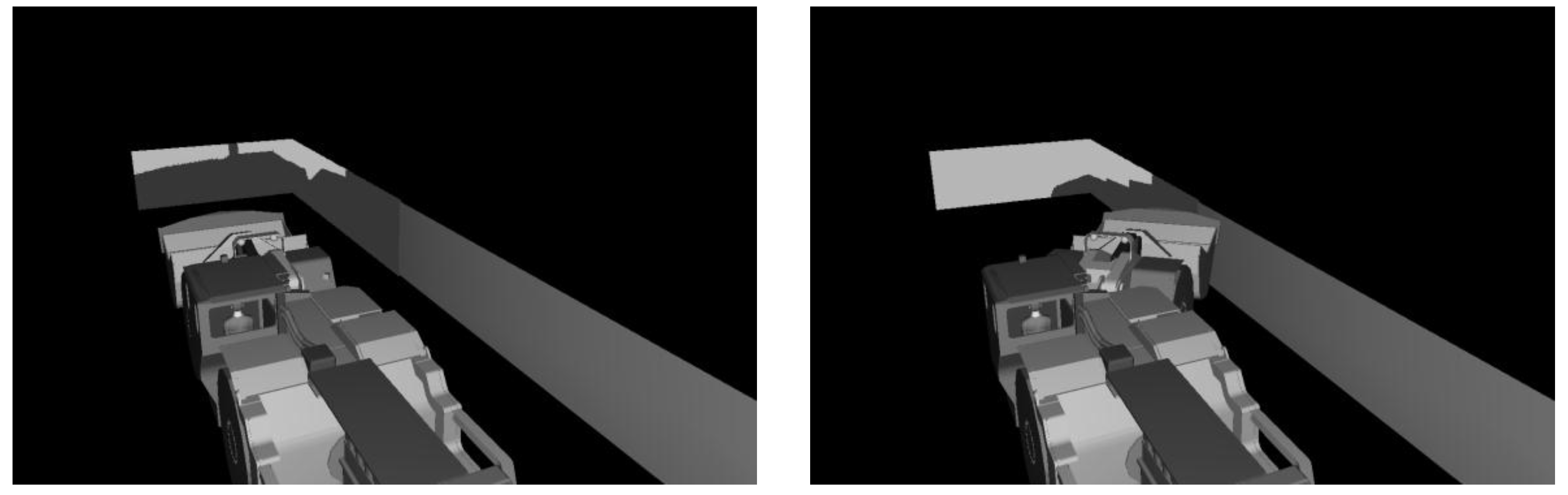
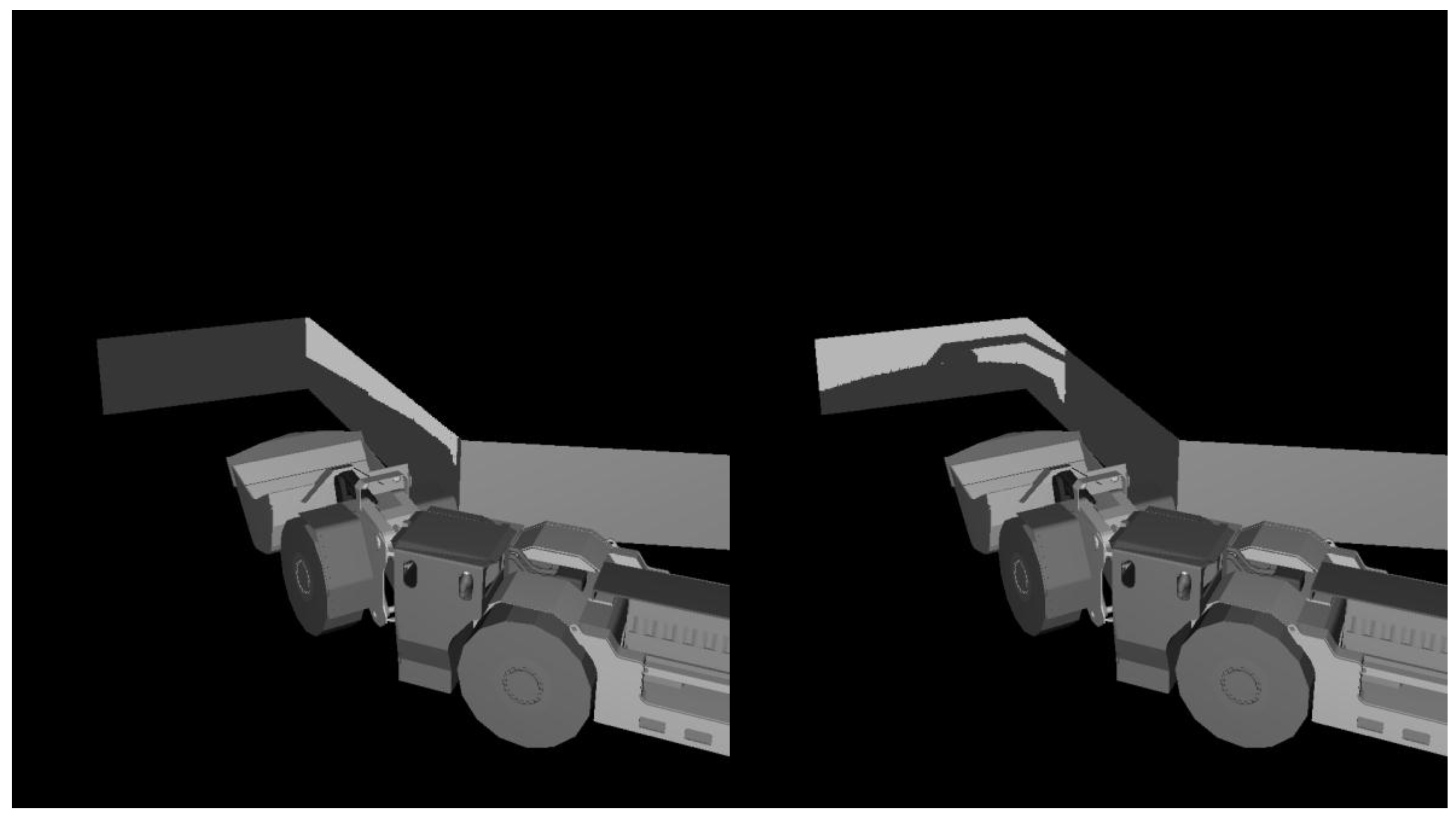
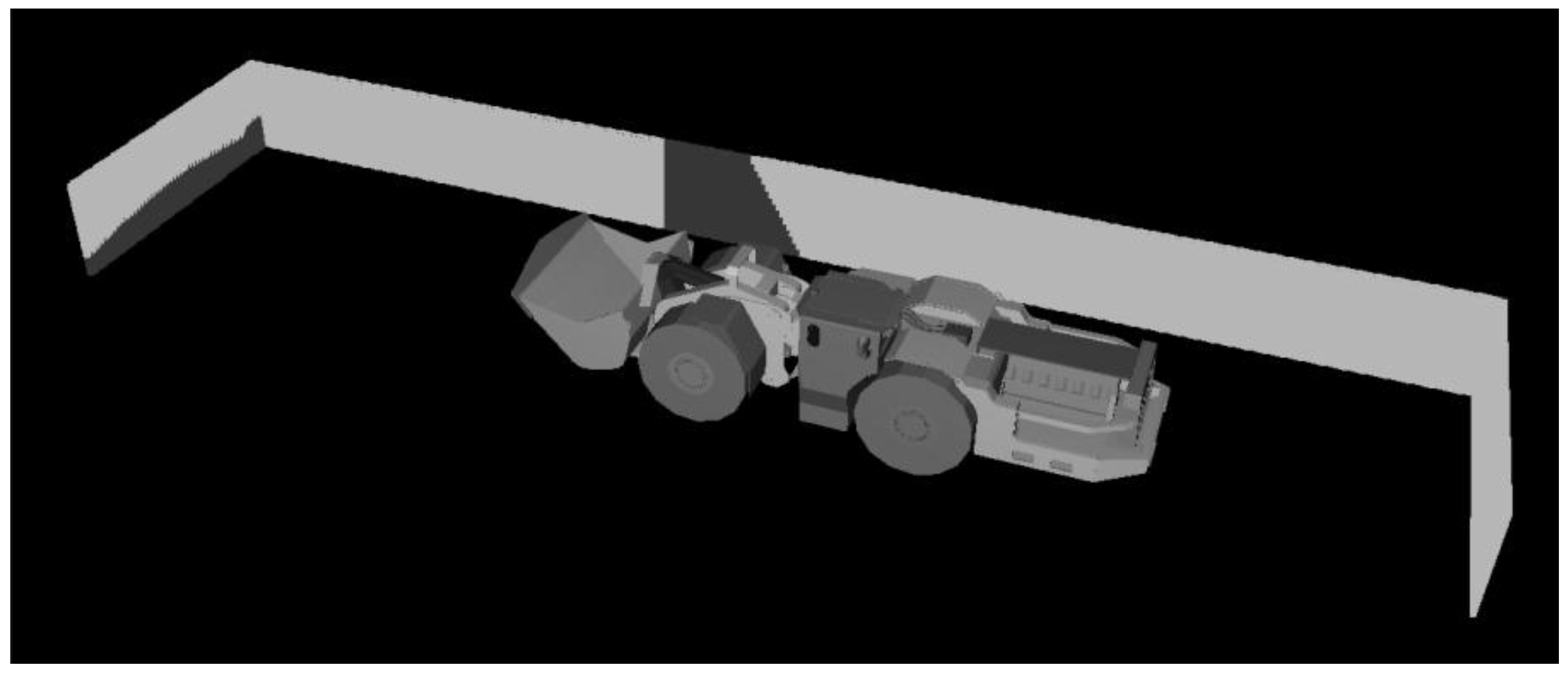
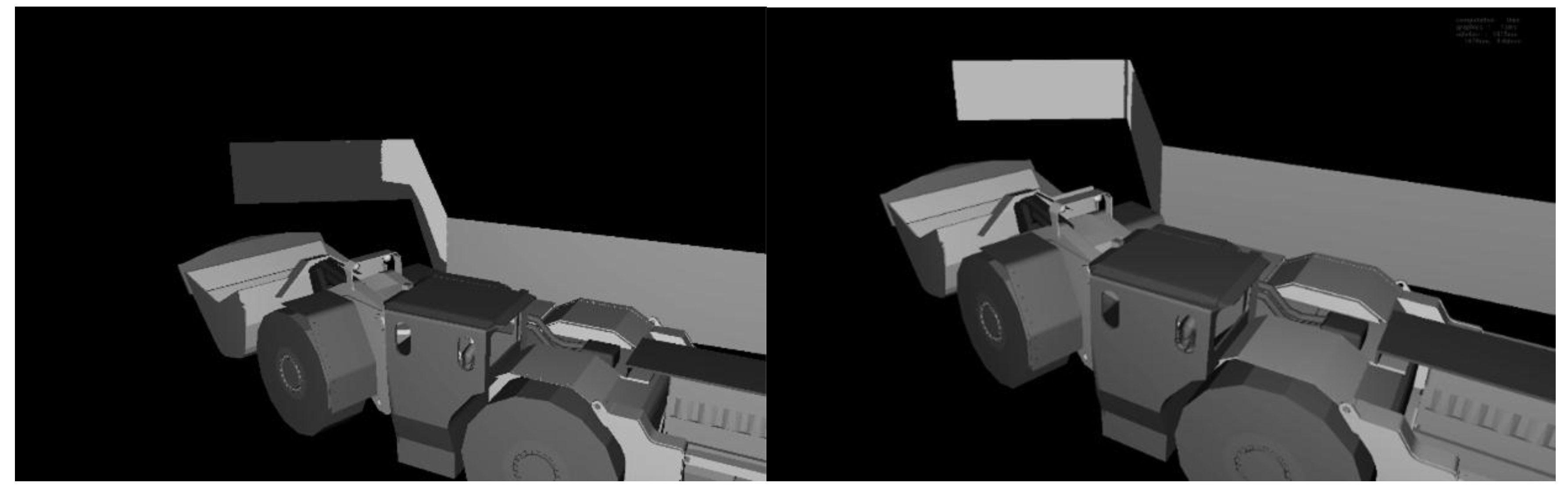
2.1. Operator and CCTV LOS in a Straight Drift When an LHD Is Straight and Articulated 38.6°

In Classic JACK 8.0, a LHD vehicle was constructed of .vrml files with a joint allowing for 38.6° of articulation at the midpoint of the machine. A 50th percentile digital male model was placed in the sitting, erect position in the LHD cab. Four planes, 2 m in height, were positioned to roughly represent a mining tunnel. Plane 2 was 10 m in length and began at the front edge (bucket of the machine) extending forward while Plane 3 was 15 m in length extending backward from the same point. Both planes 2 and 3 were positioned 1 m away from the edge of the machine. Planes 1 and 4 were 6 m in length and positioned perpendicularly (Figure 1) to the side planes at the corner positions (i.e., 10 m forward from front of bucket and 15 m rearward from front of bucket). The planes allowed for line of sight calculations to proceed in the JACK environment.
To represent a common, four-camera proximity detection system used in industry, four cubes (10 cm3) were placed and attached to locations on the LHD corresponding to current implementation in industry. Generally, these positions are chosen based on the knowledge that operators have the best line of sight down the tunnel wall on the same side as they are located while line of sight to the opposite side of the tunnel is restricted (Godwin 2014). The CCTV cameras are generally deployed on the machine to maximize forward, rearward, and opposite-side LOS while the machine is not in an articulated position. Cameras (a) and (c) (Figure 2) are intended to provide situation awareness during forward travel, while cameras (b) and (d) are positioned to improve information about rearward travel direction. For the purpose of this article, focus will be on forward travel and the enhanced view available from the forward-facing cameras (namely cameras (a) and (c) in Figure 2). Shielding planes were used to restrict the field of view to 110° horizontal view and 65° vertical view for these simulated cameras in the virtual environment. A site located in the centre of the face of each simulated camera enabled LOS data collection in the JACK environment.
With the LHD set straight in this simulated drift, the operator’s LOS from the “bottom head sight” site location, of each of the target planes was calculated as a percentage using the coverage zones feature in JACK. The line of sight coverage zone calculation provides a percentage visible, which represents the number of nodes on the coverage plane that have a clear LOS from the node back to the selected “eyesite”, which was either the camera face or operator eyepoint. This process was repeated when the machine was articulated 38.6 degrees towards target plane 3 in the straight tunnel section. This comparison provides a base level of understanding of the impact of articulation on a standard plane area.

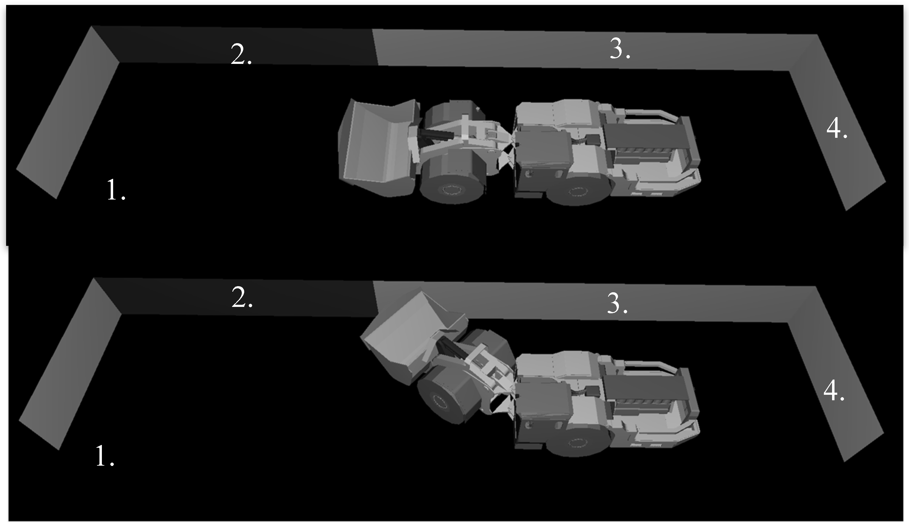
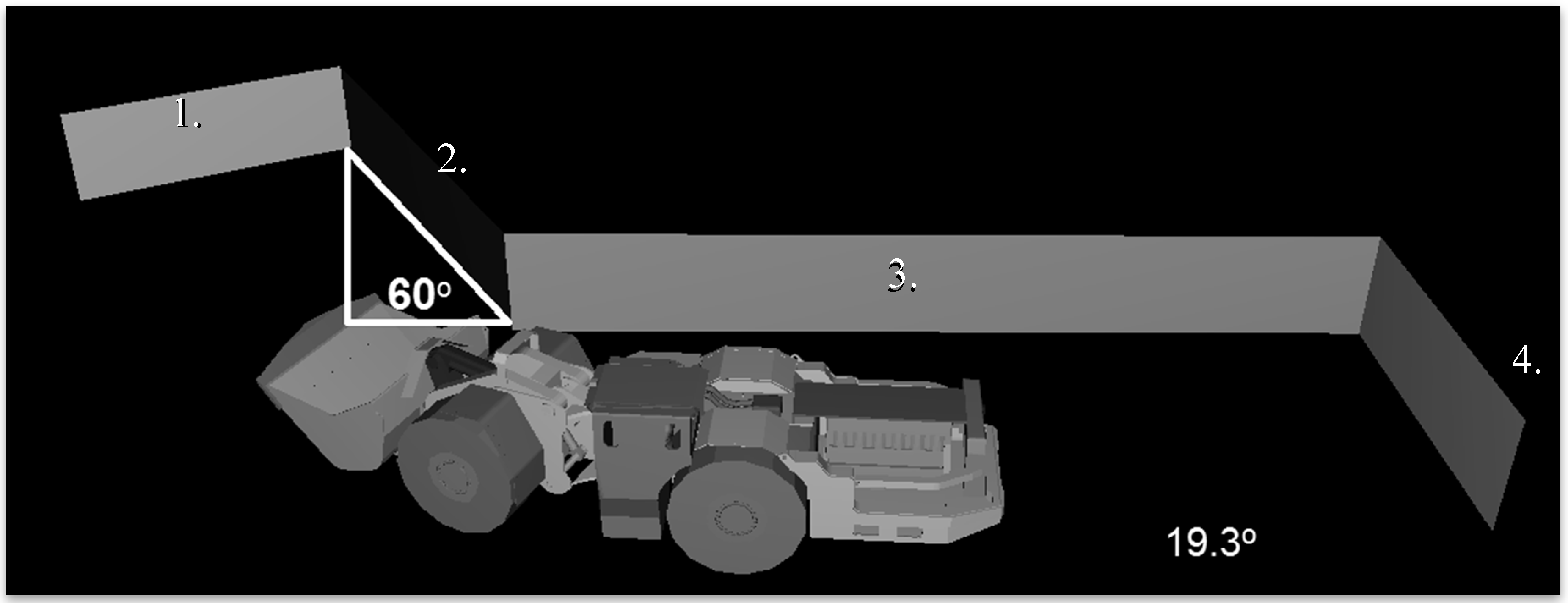
2.2. Hypothetical Operator and CCTV LOS in a 60° Drift as the Machine Turns and Articulates

A similar environment to Section 2.1 was constructed, with the exception of plane 2 orientation, which was rotated 60 degrees around the edge that connected to plane 3, creating a turn in the drift (Figure 3). Plane 1 was then attached perpendicular to plane 2 to simulate a continuous tunnel. Then using the JACK animation system, a path of six steps was constructed to move the machinery around the corner in a realistic way by fully articulating 38.6° then straightening out again. Percent visibility data was collected for the operator and camera’s line of sight at three positions: when the LHD is first articulated 19.3°, at 38.6° and finally at 19.3° again, using the same process found in Section 2.1.

3. Results

The focus of these results is on the enhanced view provided to the operator during forward travel from two forward-facing cameras. The camera results are reported as the best available view from either camera (a) or (c). However, in practice, both camera views are typically provided in the video display via a split screen. Future work may help differentiate whether one view only is better at improving situational awareness for the operator.
The impact of machine articulation on visibility is best quantified by comparing straight tunnel visibility before and after articulation. As expected from previous literature, visibility from an un-articulated machine in a straight tunnel is severely limited to all planes for the operator. The line of sight can be improved drastically for the operator by providing LOS from one of four cameras: straight drift visibility for forward or rearward travel increases to 83% on plane 3, 100% on planes 2 and 4, while plane 1 reports the least visibility at 67%. It is for this reason that manufacturers claim that similar camera systems have the potential to provide nearly 360° view around the immediate vicinity of the machine for the operator (Figure 4). To appreciate the impact of machine articulation, Figure 5 demonstrates the impact to operator LOS when the LHD is articulated to 38.6° in a straight drift. Visibility for the operator’s direct LOS actually increases from 22% to 92% on plane 1 and from 17% to 28% on plane 2 (Table 1). However, there is a significant drop in camera visibility from 100% to 61% on plane 2. The camera responsible for this added visibility also changes from camera (c) to camera (a).
The simulation of the LHD articulating around a 60° corner was paused at three relevant positions, where camera (best of either (a) or (c)) and operator line of sight were recorded (Table 2). Focus for this article is on forward plane visibility (Plane 1 and 2) for forward travel with enhanced view from cameras (a) and/or (c). In most situations, operator visibility is much worse than the best camera view (Table 2), justifying the use of this type of technology for having the capacity to improve operator situational awareness. However, there are some instances where operator view is in fact, equivalent or better than the best available camera view from either forward-facing camera.
The most drastic example of this occurs at the beginning of articulation (19.3°) just before the machine enters the corner. At this point, camera (c) provides a significantly improved view to plane 1 for the operator. However, the operator has a superior view (62% LOS) to plane 2 compared to any other cameras (19%) (Figure 6). In particular, camera (c), which was able to provide 100% view to that plane when it was located in a straight tunnel, and even 61% when fully articulated in a straight tunnel, now has 0% view due to the combination of machine articulation and tunnel design. Camera (a) can provide some enhanced view to plane 2 but only in the front right corner (Figure 6).
At position 2, when machine has moved into full articulation in the corner, a similar scenario happens where operator visibility to plane 2 (31%) is superior to what either camera can provide (Figure 7). It is useful to note that at full articulation, operator line of sight and camera line of sight is contributing somewhat unique portions of visibility with the operator able to view the top half of plane 2 while camera (a) provides a small amount of LOS (18%) to the corner (Figure 7). There is minimal LOS below 1 m along plane 2. Once again, camera (c) was intended to provide a view to this area, but articulation and tunnel dimensions have rendered it useless at this point. Operator view is also severely limited by the position of the cab post once the machine is articulated.

4. Discussion

Evaluating the impact of equipment articulation on camera system visibility is vital for refining camera system design and placement, and for determining best practices for operator use. This research has shown that camera systems have the capacity to improve operator line of sight substantially, but their effectiveness is compromised by mine layout and equipment articulation. The most common arrangement for four-camera systems on articulating machinery does not yet optimize operator visibility, specifically when navigating corners. This confirms findings from an earlier mining fatality case study [12]. Some cameras that are very useful to the operator during straightforward travel were rendered useless for enhancing view once the machine articulated. However, finding a more useful, protected spot to house cameras may not be possible. Our results demonstrate that the best camera view switches from camera (c) (located on machine body) to camera (a) (located high on the cab) during articulation. A split screen option would be ideal to minimize loss of valuable information so long as the split view does not become a distraction or difficult for operators to interpret. Future work should include determining what critical views are required to optimize line of sight with different levels of machine articulation. In the automotive industry, this has led to blind-spot information being displayed briefly to the operator at critical points in time (i.e., lane changes). Continued work in this area, specific to LHD driving, will be essential for industry-specific systems to provide the most relevant information at the ideal moment during machine navigation. Rearward travel was not tested here, but likely has similar issues due to articulation.
The potential improvement to operator line of sight is clearly evident, as the modeled four-camera system was able to substantially improve visibility on most planes when the machine was positioned without any articulation in a straight tunnel. The claim that four-camera systems provide nearly 360° of LOS around the machine is largely accurate for a non-articulated machine in a straight tunnel. The forward plane (1) remains the most obstructed area, for either the operator or the camera system. This is largely due to the large bucket and machine components on the front of the machine. This work tested a camera position that was as high as possible while still being protected (under the canopy top) and this position was only able to improve visibility up to 67% compared to the operator’s 22%. The visibility would decrease yet again when the operator was driving forwards with a heavily loaded bucket. For this reason, visibility directly in front of forward-driving, straight LHD operator is severely restricted even with a camera system in place. This work highlights the need for at least one of the forward facing cameras to be located high on the machine. From a work policy perspective, the most visible position for pedestrians in this case would be against the tunnel on the same side as the operator, in a location that is known to be visible to the operator themselves when adopting a forward-travel posture [15]. Using the extreme twisted head and trunk posture, operators can theoretically view nearly 100% of a straight tunnel on the same side as their seated position.
A key finding from this study was the impact that machine articulation has on available camera line of sight. Heading into a right turn, with a minimally-articulated LHD, the forward-facing cameras could improve operator visibility to both relevant planes (1 and 2). Notably, camera (c) positioned on the cab canopy provided 97% visibility to plane 1 when the operator could only directly view 13% of that plane. However, camera (c), which had the capacity to significantly improve LOS to plane 2 when un-articulated in a straight tunnel, is rendered completely useless (0%) due to the combination of slight machine articulation and tunnel design. At this point, the operator themselves do have a superior view to plane 2. At full articulation, the operator continues to have better visibility into the corner plane (31%) compared to either camera (a) (18%) or camera (c) (not reported but measured as 0%). Based on this knowledge, companies might want to revisit training policy for machines equipped with this type of camera system. Training procedures should be developed and implemented in order to educate operators on proper protocol for camera use during turning sequences. There may be scenarios where the operator should use their own direct vision to visually identify potential pedestrians on the far side of the tunnel prior to initiating a right-hand turn when driving forward. As the EMESRT classification of controls suggests, cameras are just one of several safety strategies [5] that need to be implemented. It also reinforces the concept that, for pedestrians wanting to be seen by underground operators, positioning themselves on the same-side of the tunnel as the operator’s cab is advantageous. Alternatively, as the machine articulates, cameras that are known to provide only limited visibility could be automatically toggled off to avoid distracting the operator, and prompting them to rely on the LOS they have directly available. Similar rules have already been implemented in the automotive industry in the form of lane-change assist views, which briefly highlight blind spots when the turning signal is activated. In this manner, situational awareness of the operator is enhanced without providing further distraction with useless information. Ongoing work aims to determine some similar, rule-based strategies that are relevant to underground LHD navigation.
Since the existing camera arrangement was not ideal for providing useful information while turning into a right-hand corner, some alternative options were considered. Moving the forward-facing camera (c) from the rear of the machine to a location on the front half would remove the issue of machine articulation limiting the camera view. However, there are very few protected positions for a camera placed on the front half of the LHD machine. This points to the need for original equipment manufacturers to incorporate camera mounts into the design of the original machine. By rotating camera (a), located on the cab, towards the opposite side from the operator, the line of sight towards both planes 1 and 2 could be improved. However, the current simulation did not investigate LOS problems and solutions for the entire radius of an LHD. It would be recommended to do a more thorough angle and placement evaluation in a field environment.
More research is needed to identify the behaviours and actions of operators when actually turning a corner if appropriate interventions are to be designed. Current system arrangements use many assumptions about operator driving behaviours. Assumed informal strategies, such as adjusting seat position and contorting the body, may not be consistently employed by operators during driving, and this would drastically change the actual perceptive abilities of the operator. More robust data using eyetracking technology with and without the use of camera system information in a field environment would be helpful to confirm how and when operators use these systems. This knowledge would allow the industry to move forward with an optimal system that considers the human factors surrounding audio-, visual-, or map-based alert systems. Further, equipment operator training should emphasize policy and procedure based on documented camera limitations rather than rely on them being a one-size fits all solution. With knowledge of the limitations of camera systems in terms of their usage on articulating machinery, management of change systems can more effectively implement future technology. This research and the 2015 Ontario Mining Health and Safety Review calls for co-operation among proximity detection developers, change management systems, and workers to improve underground safety [7].

Acknowledgments

The authors would like to recognize and thank the Ontario mining industry for their ongoing support of line of sight research, including industrial partner, Dave Winfield at Provix Inc (Alliston, ON, Canada).

Author Contributions

Nicholas Schwabe completed all the data set-up, simulation, collection and analysis, and prepared the first draft. Alison Godwin reviewed the work and wrote the discussion section to complement the findings.

Conflicts of Interest

The research team has benefitted from acquiring cameras systems typical of existing proximity systems being used in the industry. These have been donated in-kind to advance testing in the lab. Our analysis does not imply endorsement of one product over another.

References

  1. Eger, T.; Salmoni, A.; Whissell, R. Factors influencing load–haul–dump operator line of sight in underground mining. Appl. Ergon. 2004, 35, 93–103. [Google Scholar] [CrossRef] [PubMed]
  2. Burgess-Limerick, R. Avoiding collisions in underground mines. Ergon. Aust. 2011, 11, 1–4. [Google Scholar]
  3. Workplace Safety North. Pedestrian/Mobile Equipment Visibility. 2012. Available online: https://www.workplacesafetynorth.ca/sites/default/files/Pedestrian-Mobile%20Equipment%20Visibility%20-%20Technical%20Report.pdf (accessed on 26 January 2016).
  4. Groves, W.A.; Kecojevic, V.J.; Komljenovic, D. Analysis of fatalities and injuries involving mining equipment. J. Saf. Res. 2007, 38, 461–470. [Google Scholar] [CrossRef] [PubMed]
  5. Earth Moving Equipment Safety Roundtable. EMESRT—A ‘Safety by Design’ Initiative Operated by the Global Mining Industry; Earth Moving Equipment Safety Roundtable: Pinjarra Hills, Australia, 2016. [Google Scholar]
  6. Office of the Chief Coroner, Calvin Parkinson Inquest. 2009. Available online: http://canlii.ca/t/fzrx7 (accessed on 26 January 2016).
  7. The Impact of New Technology and Management of Change. Available online: http://www.labour.gov.on.ca/english/hs/pubs/miningfinal/technology.php (accessed on 26 January 2016).
  8. Ontario Ministry of the Solicitor General. Verdict of Coroner’s Jury—inquest into death of Bradley Ebbers; Document No CANLII 99645; Office of the Chief Coroner: Toronto, ON, Canada, 2011. [Google Scholar]
  9. Health and Safety Executive. Assessing Field of Vision for Operators of Earth Moving Machinery on Construction Sites; Health and Safety Executive: Liverpool, UK, 2007. [Google Scholar]
  10. Horberry, T. The health and safety benefits of new technologies in mining: A review and strategy for designing and deploying effective user-centred systems. Minerals 2012, 2, 417–425. [Google Scholar] [CrossRef]
  11. Godwin, A. Analysis of Wide and Narrow Lens PROVIX Cameras; Technical Report for PROVIX Inc.; Laurentian University: Sudbury, ON, Canada, 2014. [Google Scholar]
  12. Godwin, A.; Schwabe, N. Using a case study fatality to depict the limits of proximity detection systems for articulating, underground machinery. Saf. Sci. 2016, 87, 47–52. [Google Scholar] [CrossRef]
  13. West, J.; Haywood, M.; Dunn, P.; Eger, T.; Grenier, S.; Whissel, C. Comparison of operator line-of-sight (LOS) assessment techniques: Evaluation of an underground load haul-dump (LHD) mobile mining vehicle. J. S. Afr. Inst. Min. Metall. 2007, 107, 315. [Google Scholar]
  14. Godwin, A.; Eger, T. Using virtual computer analysis to evaluate the potential use of a camera intervention on industrial machines with line-of-sight impairments. Int. J. Ind. Ergon. 2009, 39, 146–151. [Google Scholar] [CrossRef]
  15. Eger, T.; Stevenson, J.; Callaghan, J.P.; Grenier, S. Predictions of health risks associated with the operation of load-haul-dump mining vehicles: Part 2—Evaluation of operator driving postures and associated postural loading. Int. J. Ind. Ergon. 2008, 38, 801–815. [Google Scholar] [CrossRef]
Figure 1. LHD straight and articulated 38.6° in a straight drift.
Safety 03 00017 g001
Figure 2. Cameras on the LHD lettered alphabetically clockwise.
Safety 03 00017 g002
Figure 3. LHD articulated 19.3° as it turns in a 60° drift.
Safety 03 00017 g003
Figure 4. Straight LHD in a straight drift with view from best of four-camera system (light area = LOS, dark area = no LOS).
Safety 03 00017 g004
Figure 5. Straight (left) and articulated (right) LHD in a straight drift with the operator’s line of sight (light shading) on planes 1 and 2.
Safety 03 00017 g005
Figure 6. LHD in a 60° drift articulated 19.3° with operator line of sight (left) and maximum camera visibility (right) on planes 1 and 2 (light area = LOS, dark area = no LOS).
Safety 03 00017 g006
Figure 7. LHD in a 60° drift articulated 38.6° with operator line of sight (left) and maximum camera visibility (right) on planes 1 and 2 (light area = LOS, dark area = no LOS).
Safety 03 00017 g007
Table 1. LOS for operator and camera with and without machine articulation in a straight tunnel. Camera responsible for best view listed in parentheses.
Plane (Straight Tunnel)Source Line of SightLine of Sight with No Machine ArticulationLine of Sight at 38.6° Articulation
1Operator22%92%
Camera67% (a)45% (a)
2Operator17%28%
Camera100% (c)61% (a)
Table 2. LOS for operator and camera during articulated movement at three points. Camera responsible for best view listed in parentheses.
Plane (Corner)Source Line of SightLine of Sight at Position 1 (19.3° Articulation)Line of Sight at Position 2 (38.6° Articulation)Line of Sight at Position 3 (19.3° Articulation)
1 Operator13%3%21%
Camera97% (c)45% (a)54% (a)
2 Operator62%31%3%
Camera19% (a)18% (a)63% (c)

