
Design of Manual Handling Carts: A Novel Approach Combining Corrective Forces and Modelling to Prevent Injuries


Abstract
1. Introduction
- (1)
- A novel method is proposed for changing traditional test methods in manual handling equipment design standards. This new method retains the steel plate as a reference floor while incorporating corrective forces in order to take into account the real conditions of use, notably the type of wheel and the type of floor. This method consists of combining a pushing force model of an equipment with corrective forces;
- (2)
- The definition and assessment of corrective forces, based on resistive forces measured for different types of wheels in contact with various floor types, in order to correct the pushing force measured on the steel plate;
- (3)
- The provision of different abaci taking into account the type of wheel (its tread and bearing), the load carried by the wheel and the hardness of the base foam of floor coverings;
- (4)
- A basic mathematical model of the pushing force required to move a four-wheeled item of equipment, which combined with different corrective force abaci, allows us to assess the moving force (as a function of floor and wheel combinations), and thus to estimate the maximum load in real usage conditions.
2. Materials and Methods
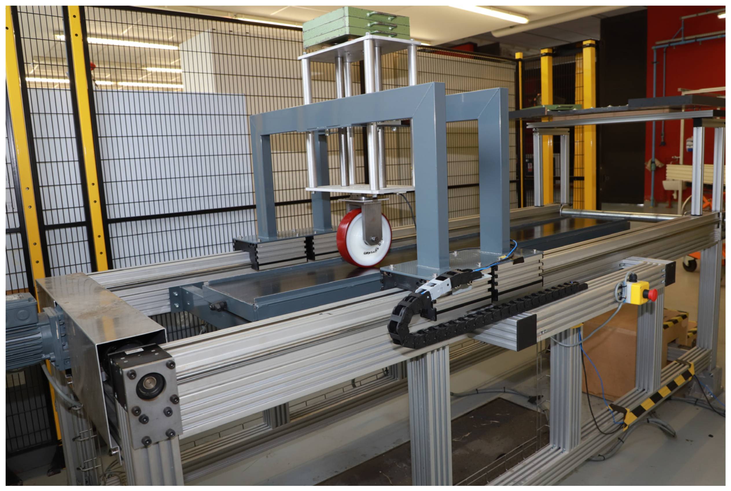
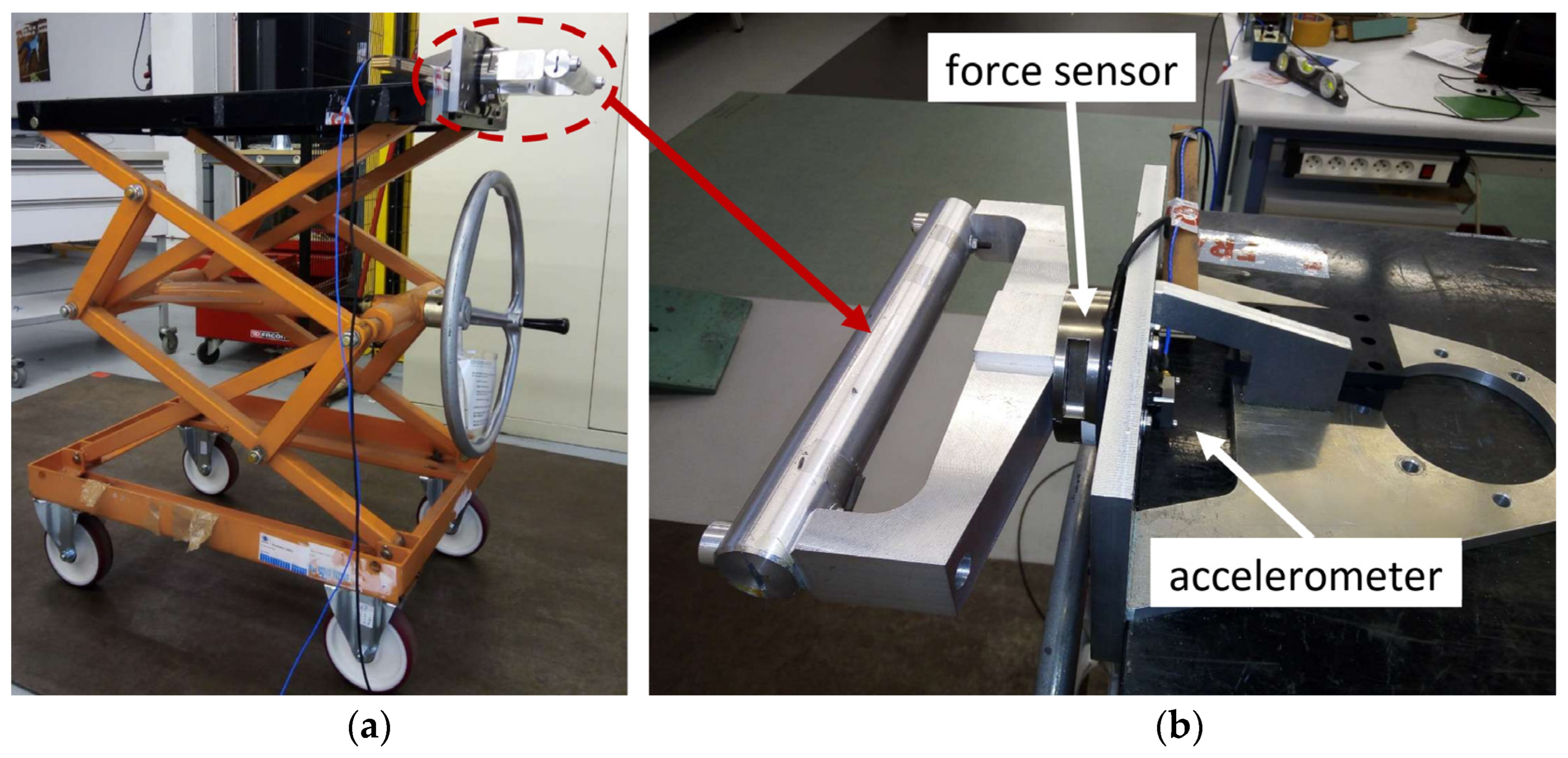
2.1. Definition of Corrective Forces for a Single-Wheel
2.2. Transition from a Single-Wheel to a Four-Wheeled Cart System to Estimate the Pushing Force
- -
- calculate the pushing force for any floor coverings in the knowledge of different pieces of information: the pushing force measured on a steel plate covering and the corrective forces corresponding to the type of rear and front wheels fitted the four-wheeled cart (these forces depend on the floor coverings under consideration, and the load carried by the rear and front wheels);
- -
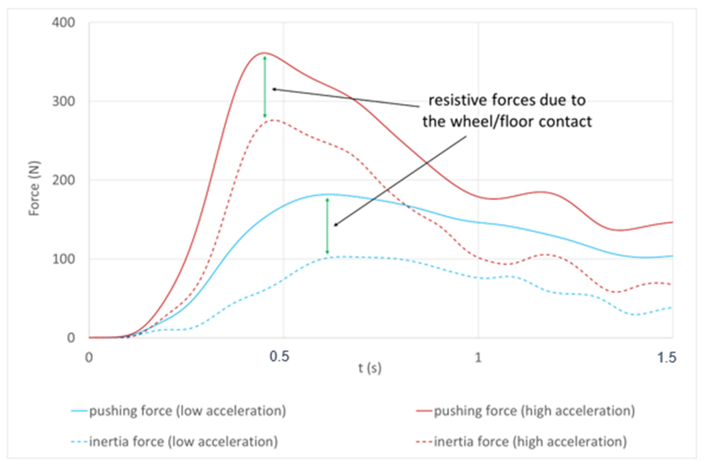
- predict the pushing force of any cart in the knowledge of the acceleration applied to the equipment and the resistive forces of any wheels in contact with the floor coverings under consideration;
- -
- take into account the differences between front and rear wheels (diameter, load distribution, etc.) as well as the acceleration of the equipment.
2.3. Experimental Validation of Combination of Corrective Forces and Pushing Force Model
3. Results
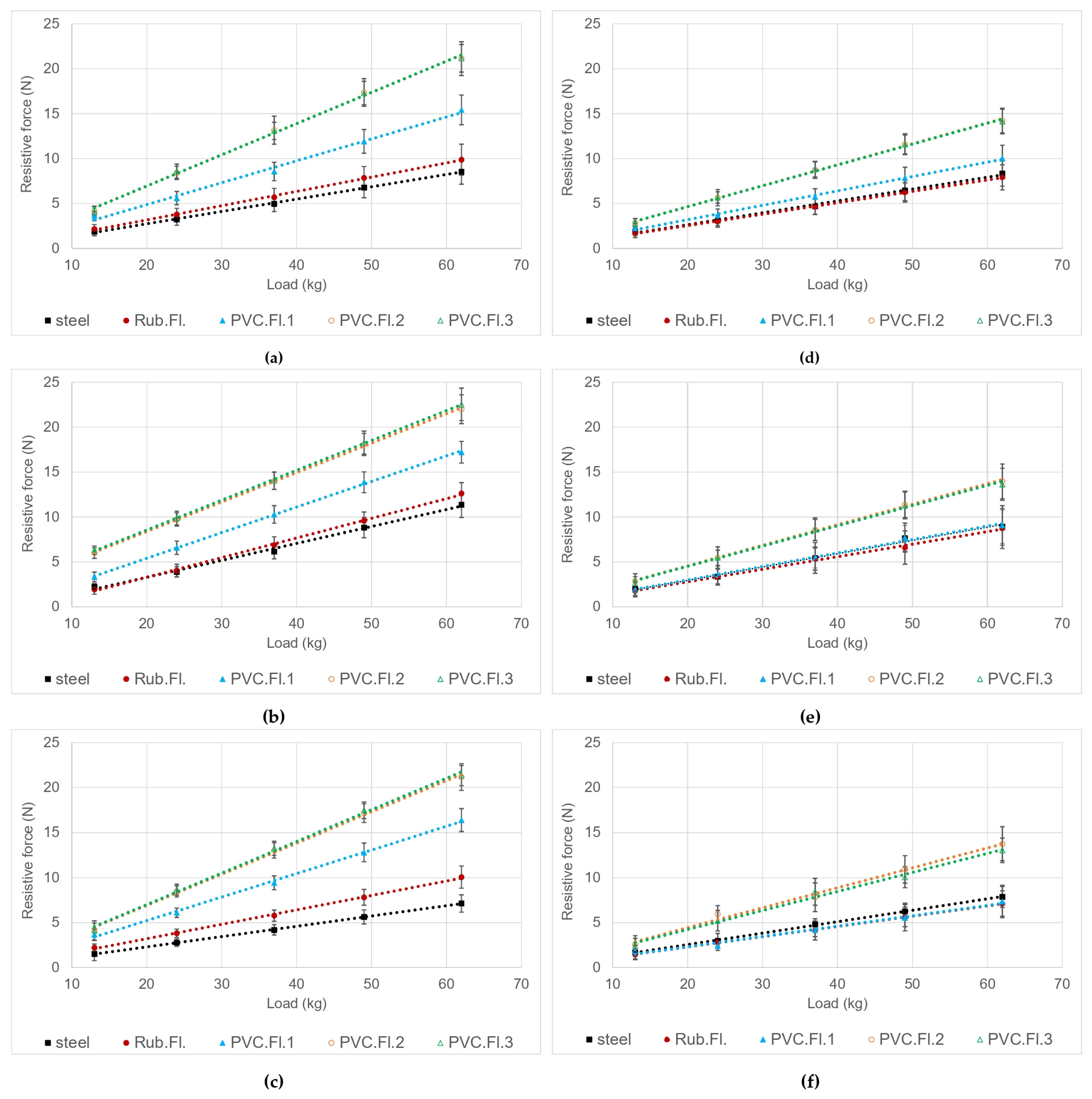
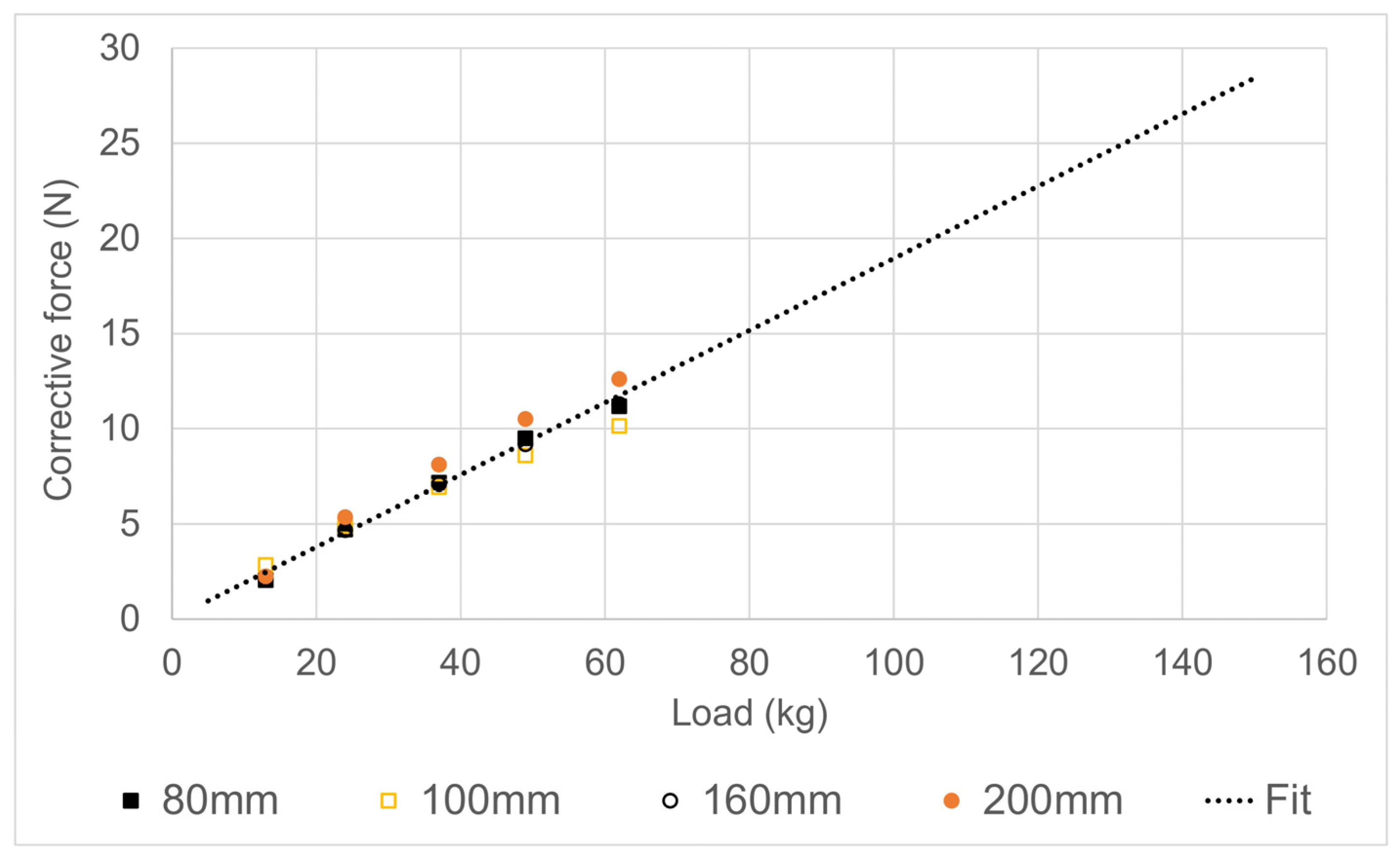
3.1. Resistive Forces
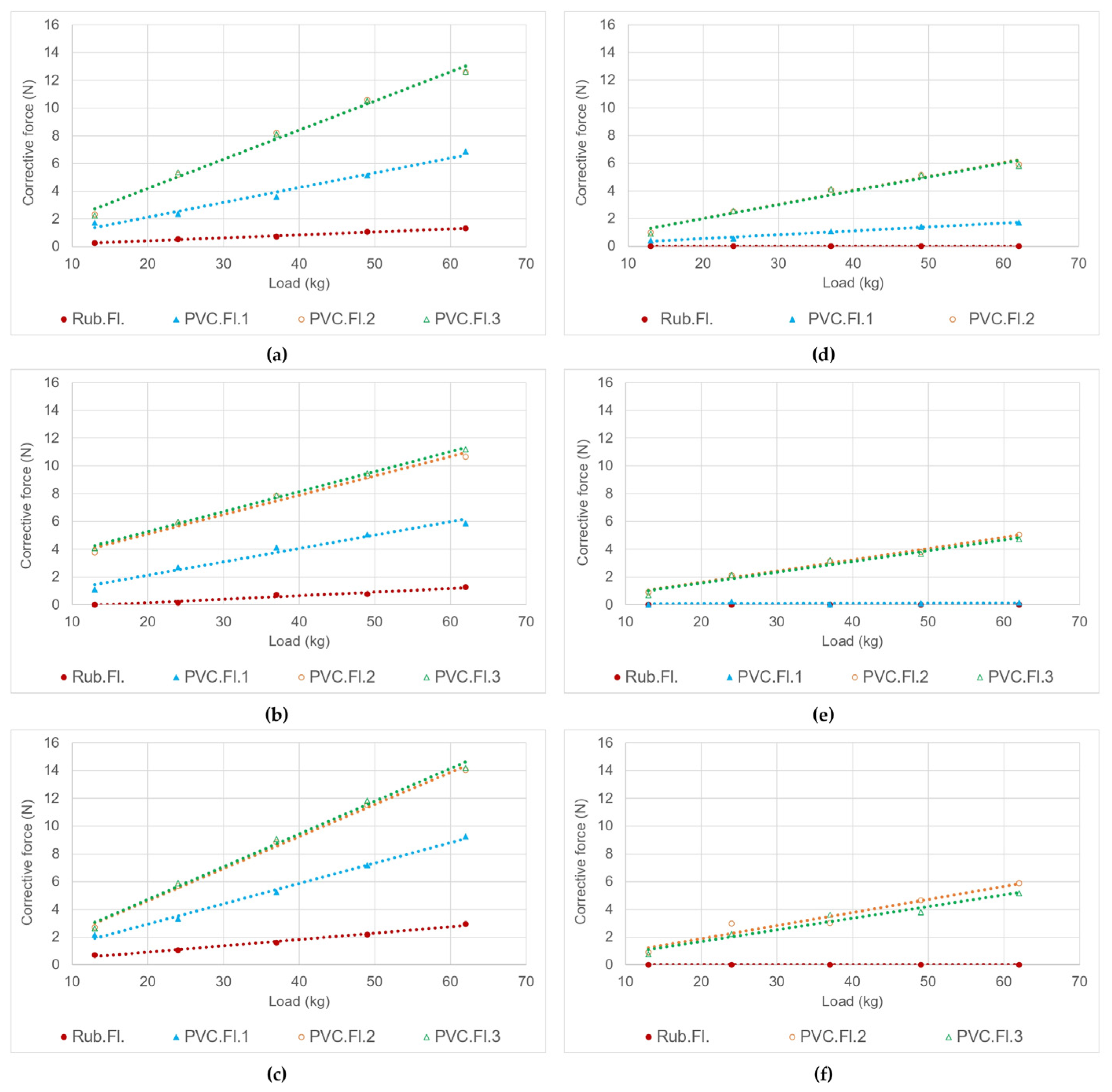
3.2. Evaluation of Corrective Forces
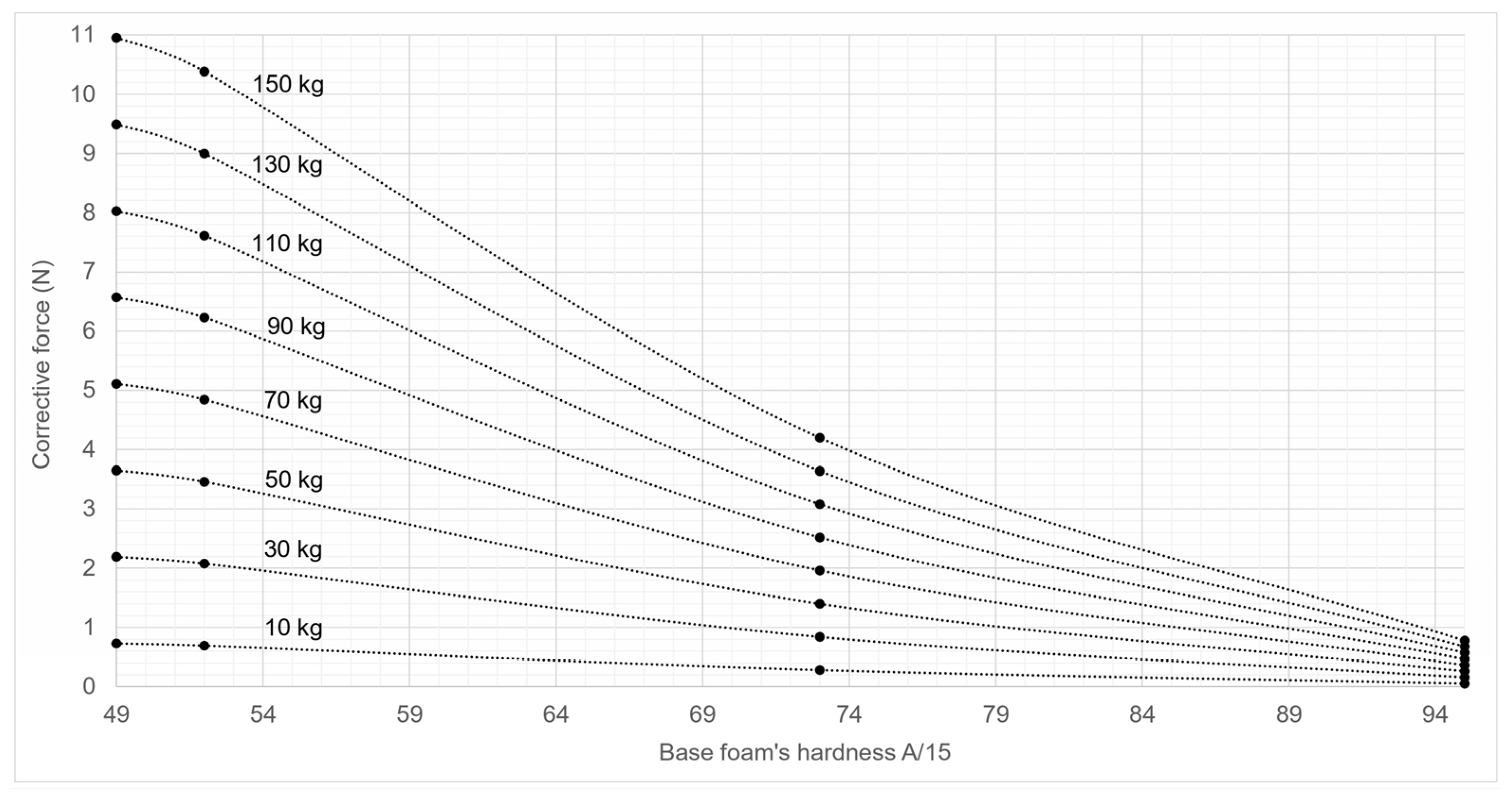
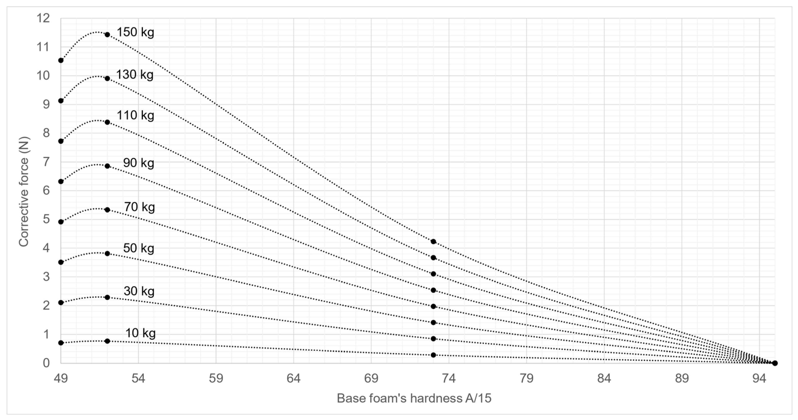
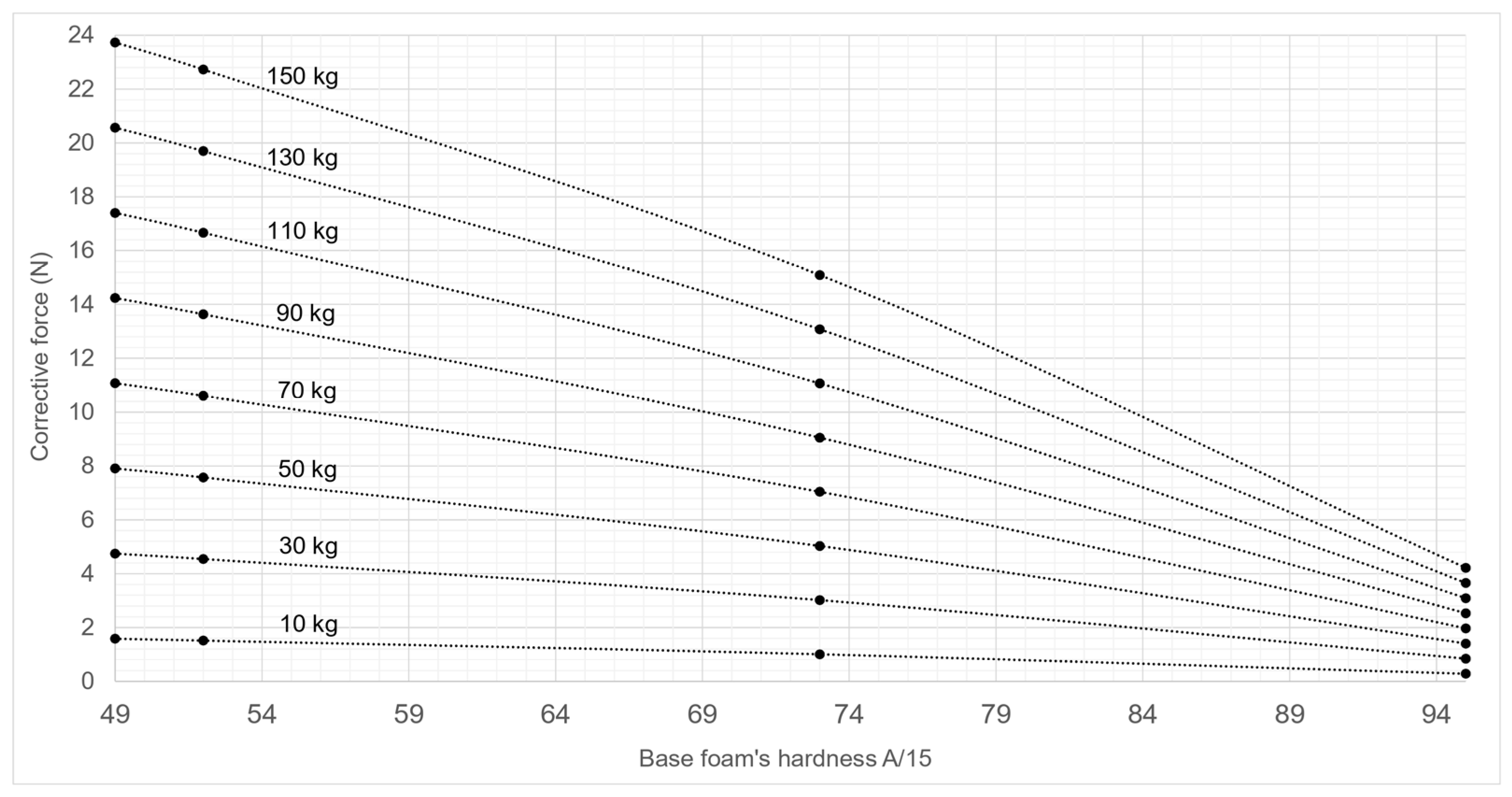
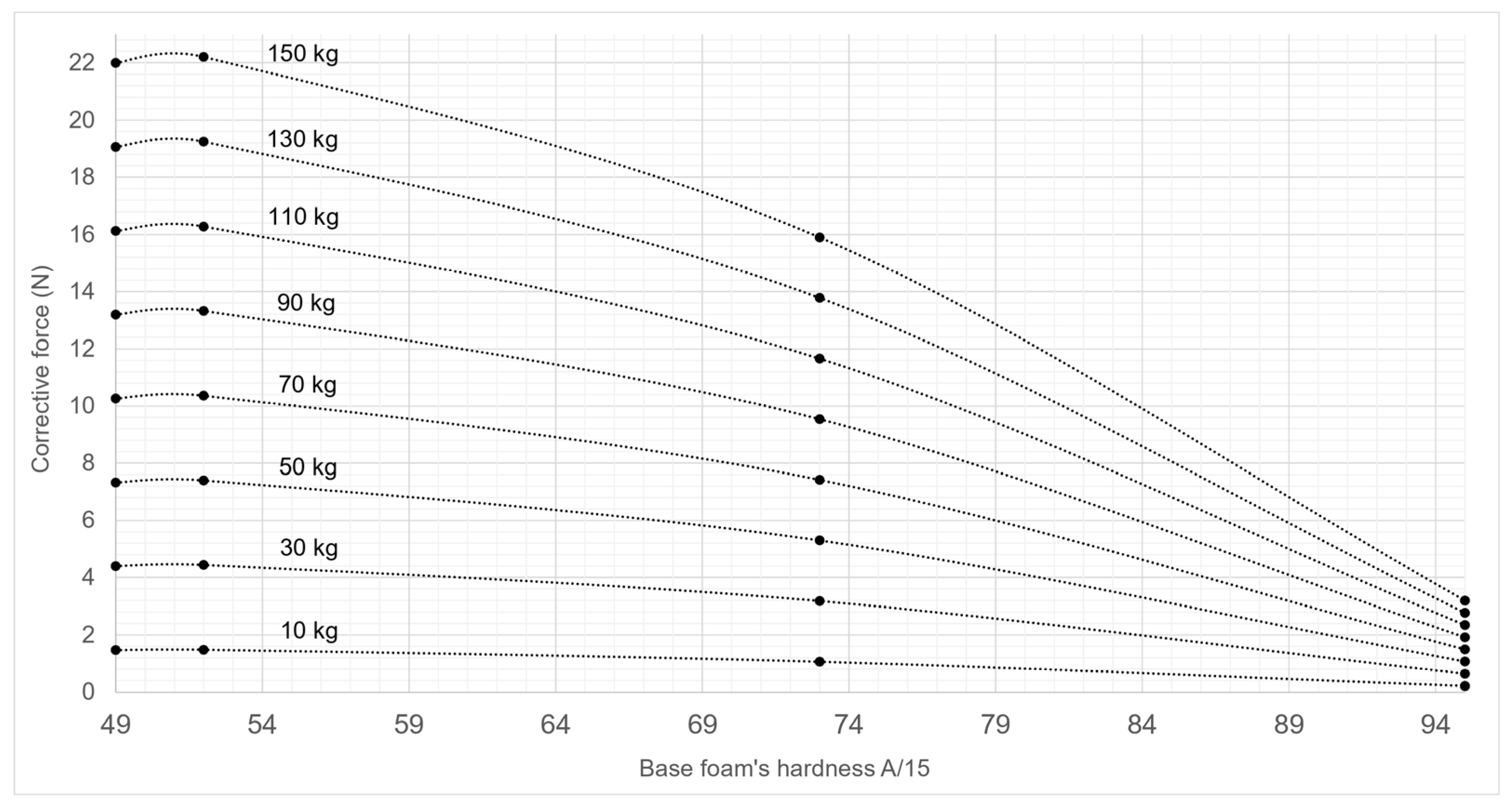
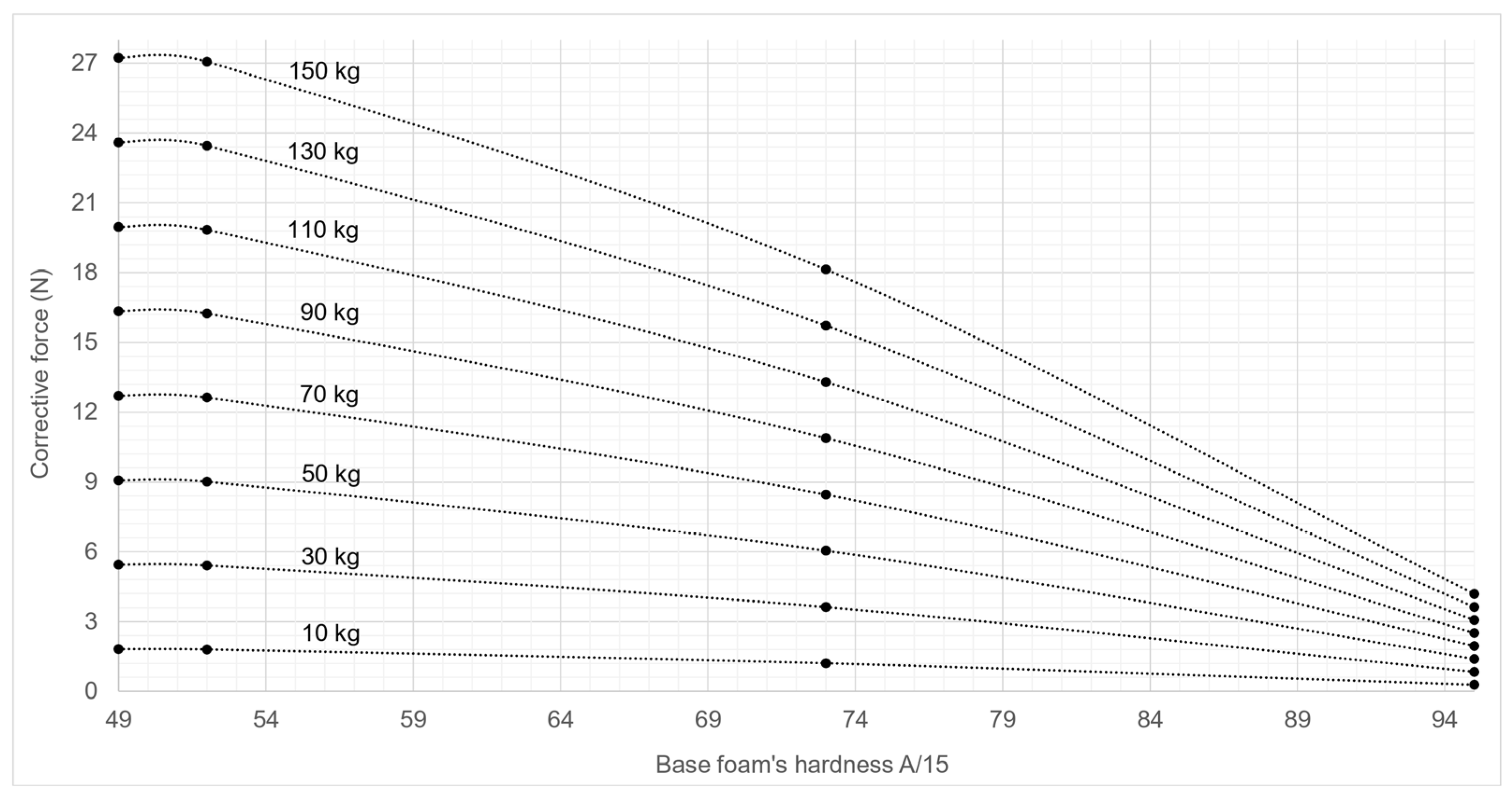
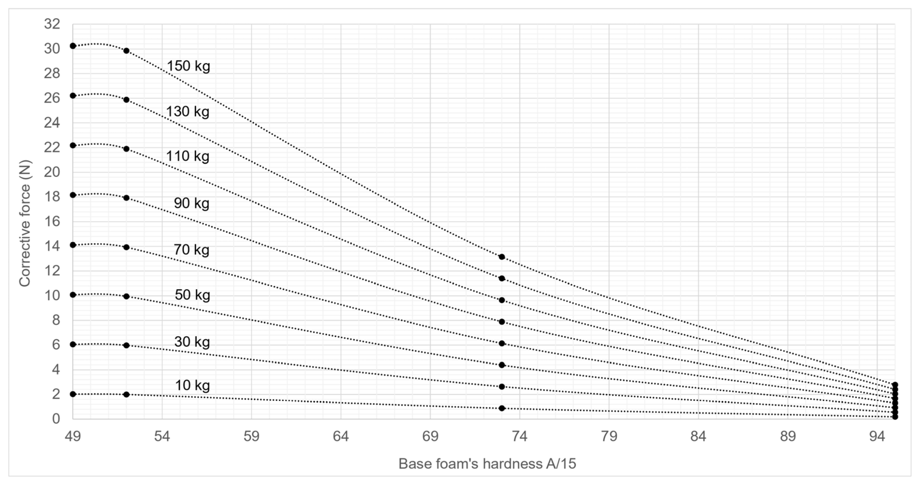
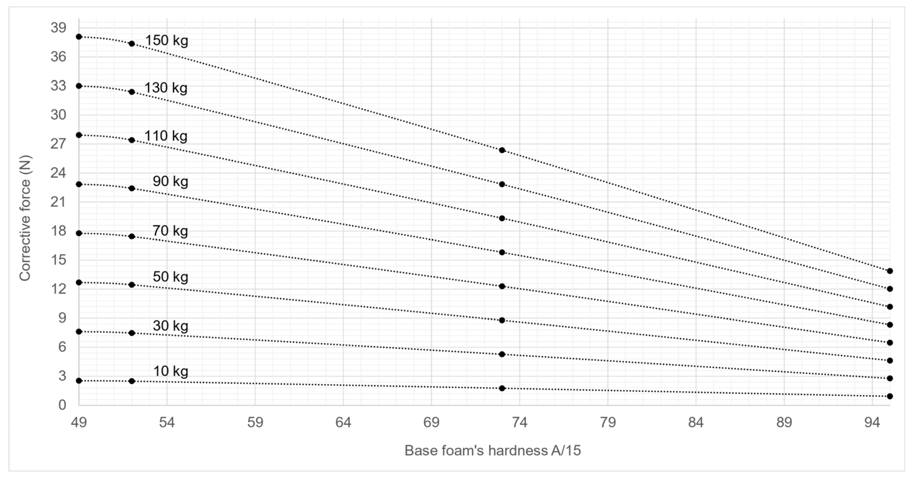
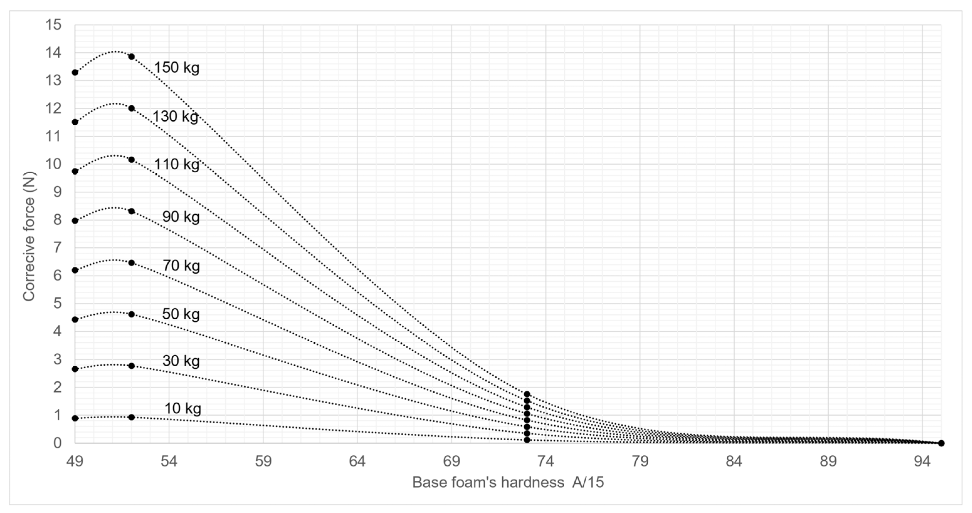
3.3. Corrective Forces Abacus
3.4. Pushing Force Model
3.5. Comparison of Experimental and Modelled Pushing Forces
4. Discussion
- o
- between A/15: 52 and A/15: 73, the interval for which the variations in corrective forces may likely be the most significant due to the low hardness of the floor covering’s base foam (softness);
- o
- a study of corrective forces for floor covering’s base foam hardness between A/15: 73 and A/15: 95 (hardest floor coverings).
5. Conclusions
Funding
Institutional Review Board Statement
Informed Consent Statement
Data Availability Statement
Acknowledgments
Conflicts of Interest
Appendix A. Corrective Forces Abaci
- Step 1: identify the type of wheel’s tread and bearing of the rear and front wheel axles of the equipment;
- Step 2: identify the total weight (the empty weight of the equipment and the load weight), and the front/rear load distribution ratio;
- Step 3: determine the floor covering’s base foam hardness (in Shore A/15);
- Step 4: for each wheel axle, refer to the corresponding abacus for the type of wheel it equips. Identify the value of the floor covering’s base foam hardness on the x-axis. Select the curve corresponding to the total weight carried by each wheel axle. For each wheel axle, record on the y-axis the value of the corrective force to be applied (ξr and ξf for the rear and front wheel axles);
- Step 5: to evaluate the effort to move the equipment on the selected floor covering, insert the values of the corrective forces (ξr and ξf) into the Equation (10).


Appendix B. Pushing Force Model
- solid 1—equipment’s loaded frame;
- solid 2—front wheel;
- solid 3—rear wheel.
Appendix B.1. FPD Application to Solid 1
Appendix B.1.1. Action of Weight
Appendix B.1.2. Action of Pushing Force
Appendix B.1.3. Action Contact of Solid 2 on Solid 1
Appendix B.1.4. Action Contact of Solid 3 on Solid 1
- About the x-axis:
- About the y-axis:
Appendix B.2. FPD Application to Solid 2
Appendix B.2.1. Action Contact of Solid 1 on Solid 2
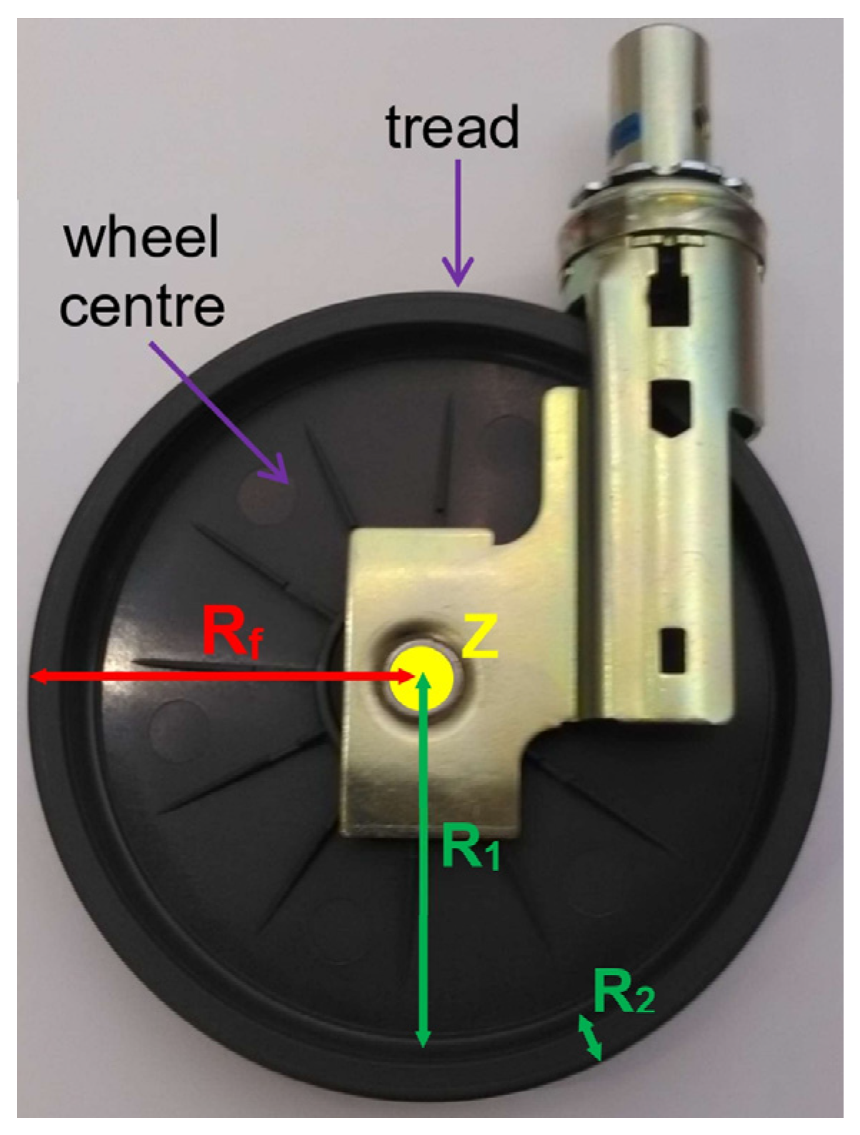
Appendix B.2.2. Action of Ground on Front Train
- the wheel centre’s radius is R1, its thickness is h1 and its mass is M1. The wheel centre is described as a solid cylinder of radius R1 and height h1;
- the tread’s thickness is R2, its width is h2 and its mass is M2. The tread is described as a hollow cylinder of inner radius R1, outer radius Rf and height h2.
- about the x-axis:
- about the y-axis:
- about the z-axis:
Appendix B.3. FPD Application to Solid 3
Appendix B.3.1. Action Contact of Solid 1 on Solid 3
Appendix B.3.2. Action of Ground on Rear Train
- about the x-axis:
- about the y-axis:
- about the z-axis:
Appendix B.4. Expression of Pushing Force FT
References
- EU-OSHA. OSH in Figures: Work-Related Musculoskeletal Disorders in the EU—Facts and Figures. 2010. Available online: https://osha.europa.eu/en/publications/osh-figures-work-related-musculoskeletal-disorders-eu-facts-and-figures (accessed on 4 March 2025).
- DARES. Les Expositions Aux Risques Professionnels: Les Contraintes Physiques—Enquête SUMER 2017. 2019. Available online: https://dares.travail-emploi.gouv.fr/sites/default/files/pdf/synthese_stat_-_contraintes_physiques__4_septembre.pdf (accessed on 4 March 2025).
- Pinupong, C.; Jalayondeja, W.; Mekhora, K.; Bhuanantanondh, P.; Jalayondeja, C. The Effects of Ramp Gradients and Pushing–Pulling Techniques on Lumbar Spinal Load in Healthy Workers. Saf. Health Work 2020, 11, 307–313. [Google Scholar] [CrossRef] [PubMed]
- Baril-Gingras, G.; Lortie, M. The handling of objects other than boxes: Univariate analysis of handling techniques in a large transport company. Ergonomics 1995, 38, 905–925. [Google Scholar] [CrossRef] [PubMed]
- Hoozemans, M.J.M.; van der Beek, A.J.; Frings-Dresen, M.H.W.; van Dijk, F.J.H.; van der Woude, L.H.V. Pushing and pulling in relation to musculoskeletal disorders: A review of risk factor. Ergonomics 1998, 41, 757–781. [Google Scholar] [CrossRef] [PubMed]
- Hoozemans, M.J.M.; van der Beek, A.J.; Frings-Dresen, M.H.W.; van der Woude, L.H.V.; van Dijk, F.J.H. Pushing and pulling in association with low back and shoulder complaints. Occup. Environ. Med. 2002, 59, 696–702. [Google Scholar] [CrossRef]
- Hoozemans, M.J.M.; Kuijer, P.P.; Kingma, I.; van Dieën, J.H.; de Vries, W.H.; van der Woude, L.H.V.; Veeger, D.J.; van der Beek, A.J.; Frings-Dresen, M.H. Mechanical loading of the low back and shoulders during pushing and pulling activities. Ergonomics 2004, 15, 1–18. [Google Scholar] [CrossRef]
- Desbrosses, K.; Meyer, J.P.; Didry, G. Benchmarks in pushing-pulling forces. Hygiène Et Sécurité Du Trav. 2012, 228, 49–58. Available online: https://www.inrs.fr/dms/inrs/CataloguePapier/HST/TI-ND-2365/nd2365.pdf (accessed on 4 March 2025).
- Argubi-Wollesen, A.; Wollesen, B.; Leitner, M.; Mattes, K. Human Body Mechanics of Pushing and Pulling: Analyzing the Factors of Task-related Strain on the Musculoskeletal System. Saf. Health Work 2017, 8, 11–18. [Google Scholar] [CrossRef]
- Brace, T. The Dynamics of Pushing and Pulling in the Workplace: Assessing and Treating the Problem. AAOHN J. 2005, 53, 224–229. [Google Scholar] [CrossRef]
- EU-OSHA. Work-Related Musculoskeletal Disorders: Prevalence, Costs and Demographics in the EU, European Risk Observatory Report. 2019. Available online: https://osha.europa.eu/sites/default/files/Work-related_MSDs_prevalence_costs_and_demographics_in_the_EU_report.pdf (accessed on 4 March 2025).
- NIOSH. Work Practices Guide for Manual Lifting. Technical Report. 1981. Available online: https://www.cdc.gov/niosh/docs/81-122/default.html (accessed on 4 March 2025).
- Kingma, I.; Kuijer, P.P.F.M.; Hoozemans, M.J.M.; van Dieen, J.H.; van der Beek, A.J.; Frings-Dresen, M.H.W. Effect of design of two-wheeled containers on mechanical loading. Int. J. Ind. Ergon. 2003, 31, 73–86. [Google Scholar] [CrossRef]
- Safiri, S.; Kolahi, A.A.; Cross, M.; Hill, C.; Smith, E.; Carson-Chahhoud, K.; Mansournia, M.A.; Almasi-Hashiani, A.; Ashrafi-Asgarabad, A.; Kaufman, J.; et al. Prevalence, deaths, and disability-adjusted life years due to musculoskeletal disorders for 195 countries and territories 1990–2017. Arthritis Rheumatol. 2021, 73, 702–714. [Google Scholar] [CrossRef]
- Van der Beek, A.J.; Frings-Dresen, M.H.W.; van Dijk, F.J.H.; Kemper, H.C.G.; Meijman, T.F. Loading and unloading by lorry drivers and musculoskeletal complaints. Int. J. Ind. Ergon. 1993, 12, 13–23. [Google Scholar] [CrossRef]
- Hughes, R.E.; Silverstein, B.A.; Evanoff, B.A. Risk factors for work-related musculoskeletal disorders in an aluminum smelter. Am. J. Ind. Med. 1997, 32, 66–75. [Google Scholar] [CrossRef]
- Jansen, J.P.; Hoozemans, M.J.; van der Beek, A.J.; Frings-Dresen, M.H. Evaluation of ergonomic adjustments of catering carts to reduce external pushing forces. Appl. Ergon. 2002, 33, 117–127. [Google Scholar] [CrossRef] [PubMed]
- Smedley, J.; Inskip, H.; Trevelyan, F.; Buckle, P.; Cooper, C.; Coggon, D. Risk factors for incident neck and shoulder pain in hospital nurses. Occup. Environ. Med. 2003, 60, 864–869. [Google Scholar] [CrossRef]
- World Health Organization. International Classification of Diseases 11th Revision (ICD-11). 2020. Available online: https://icd.who.int/en (accessed on 4 March 2025).
- Sebbag, E.; Felten, R.; Sagez, F.; Sibilia, J.; Devilliers, H.; Arnaud, L. The world-wide burden of musculoskeletal diseases: A systematic analysis of the World Health Organization Burden of Diseases Database. Ann. Rheum. Dis. 2019, 41, 844–848. [Google Scholar] [CrossRef] [PubMed]
- Guan, S.Y.; Zheng, J.X.; Sam, N.B.; Xu, S.; Shuai, Z.; Pan, F. Global burden and risk factors of musculoskeletal disorders among adolescents and young adults in 204 countries and territories, 1990–2019. Autoimmun. Rev. 2023, 22, 103361. [Google Scholar] [CrossRef]
- Briggs, A.M.; Woolf, A.D.; Dreinhöfer, K.; Homb, N.; Hoy, D.G.; Kopansky-Giles, D.; Åkesson, K.; March, L. Reducing the global burden of musculoskeletal conditions. Bull. World Health Organ. 2018, 96, 366–368. [Google Scholar] [CrossRef]
- ISO 11228-2; Ergonomics Manual Handling Part 2: Pushing and Pulling. ISO: Geneva, Switzerland, 2007.
- Amendment of ISO 11228-2; AMENDMENT 1 of Ergonomics Manual handling Part 2: Pushing and Pulling. ISO: Geneva, Switzerland, 2022.
- NF X35-109; Ergonomics-Manual Load Handling for Lifting, Moving and Pushing/Pulling-Analysis Methodolgy and Threshold Values. AFNOR: La Plaine Saint-Denis, France, 2011.
- EN 1005-3+A1; Safety of Machinery-Human Physical Performance-Part 3: Recommended Force Limits for Machinery Operation. CEN: Brussels, Belgium, 2008.
- Snook, S.; Ciriello, V.M. The design of manual handling tasks: Revised tables of maximum acceptable weights and forces. Ergonomics 1991, 34, 1197–1213. [Google Scholar] [CrossRef]
- Marras, W.S.; Knapik, G.G.; Ferguson, S. Lumbar spine forces during manoeuvring of ceiling-based and floor-based floor-based patient transfer devices. Ergonomics 2009, 52, 384–397. [Google Scholar] [CrossRef]
- van der Beek, A.J.; Hoozemans, M.J.M.; Frings-Dresen, M.H.W.; Burdorf, A. Assessment of exposure to pushing and pulling in epidemiological field studies: An overview of methods, exposure measures, and measurement strategies. Int. J. Ind. Ergon. 1999, 24, 417–429. [Google Scholar] [CrossRef]
- Al-Eisawi, K.; Kerk, C.; Congleton, J.; Amendola, A.; Jenkins, O.C.; Gaines, W. The effect of handle height and cart load on the initial hand forces in cart pushing and pulling. Ergonomics 1999, 42, 1099–1113. [Google Scholar] [CrossRef]
- Xu, X.; Lin, J.; Boyer, J. Shoulder joint loading and posture during medicine cart pushing task. J. Occup. Environ. Hyg. 2013, 10, 446–454. [Google Scholar] [CrossRef] [PubMed]
- Bennett, A.; Todd, A.; Desai, S. Pushing and pulling technique and load effects: An electromyographical study. Work 2011, 38, 291–299. [Google Scholar] [CrossRef] [PubMed]
- Kao, H.C.; Lin, C.J.; Lee, Y.H.; Chen, S.H. The effects of direction of exertion, path, and load placement in nursing cart pushing and pulling tasks: An electromyographical study. PLoS ONE 2015, 10, e0140792. [Google Scholar] [CrossRef]
- EN ISO 10535; Hoists for the Transfer of Disabled Persons-Requirements and Test Methods. ISO: Geneva, Switzerland, 2021.
- EN 1757-3; Safety of Industrial Trucks-Pedestrian Propelled Manual and Semi-Manual Trucks-Part 3: Platform Trucks. CEN: Brussels, Belgium, 2003.
- Al-Eisawi, K.W.; Kerk, C.J.; Congleton, J.J.; Amendola, A.A.; Jenkins, O.C.; Gaines, W. Factors affecting minimum push and pull forces of manual carts. Appl. Ergon. 1999, 30, 235–245. [Google Scholar] [CrossRef]
- Das, B.; Wimpee, J.; Das, B. Ergonomics evaluation and redesign of a hospital meal cart. Appl. Ergon. 2002, 33, 309–318. [Google Scholar] [CrossRef]
- Garg, A.; Waters, T.; Kapellusch, J.; Karwowski, W. Psychophysical basis for maximum pushing and pulling forces: A review and recommendations. Int. J. Ind. Ergon. 2014, 44, 281–291. [Google Scholar] [CrossRef]
- Ott, J.; Wilson-Jene, H.; Koontz, A.; Pearlman, J. Evaluation of rolling resistance in manual wheelchair wheels and casters using drum-based testing. Disabil. Rehabil. Assist. Technol. 2022, 17, 719–730. [Google Scholar] [CrossRef]
- Sawatzky, B.; Kim, W.; Denison, I. The ergonomics of different tyres and tyre pressure during wheelchair propulsion. Ergonomics 2004, 47, 1475–1483. [Google Scholar] [CrossRef]
- Park, S.Y.; Kim, S.H.; Park, D.J. Effect of the Air-Pressure Differences of the Wheelchair Tires on user’s Upper Extremity Muscle Activities and Acceleration Changes. Int. J. Eng. Res. Technol. 2020, 9, 3266–3271. [Google Scholar] [CrossRef]
- Gille, S.; Clerc-Urmès, I. A New Approach to Prevent Injuries Related to Manual Handling of Carts: Correcting Resistive Forces between Floors and Wheels to Evaluate the Maximal Load Capacity. Safety 2024, 10, 69. [Google Scholar] [CrossRef]
- EN ISO 868; Plastics and Ebonite-Determination of Indentation Hardness by Means of a Durometer (Shore Hardness). ISO: Geneva, Switzerland, 2003.
- Hofstad, M.; Patterson, P.E. Modelling the propulsion characteristics of a standard wheelchair. J. Rehabil. Res. Dev. 1994, 31, 129–137. [Google Scholar] [PubMed]
- Weston, E.B.; Aurand, A.; Dufour, J.S.; Knapik, G.G.; Marras, W.S. Biomechanically determined hand force limits protecting the low back during occupational pushing and pulling tasks. Ergonomics 2018, 61, 853–865. [Google Scholar] [CrossRef] [PubMed]
- Sakka, S.; Chablat, D.; Ma, R.; Bennis, F. Predictive model of the human muscle fatigue: Application to repetitive push-pull tasks with light external load. Int. J. Hum. Factors Model. Simul. 2015, 5, 81–97. [Google Scholar] [CrossRef]
- Hoffman, S.; Reed, M.; Chaffin, D. The Relationship between Hand Force Direction and Posture during Two-Handed Pushing Tasks. Proc. Hum. Factors Ergon. Soc. Annu. Meet. 2007, 51, 928–932. [Google Scholar] [CrossRef]
- Marras, W.; Karwowski, W. The Occupational Ergonomics Handbook, 2nd ed.; CRC Press: Boca Raton, FL, USA, 1999; p. 2065. [Google Scholar]
- van der Beek, A.J.; Kluver, B.D.; Frings-Dresen, M.H.; Hoozemans, M.J. Gender differences in exerted forces and physiological load during pushing and pulling of wheeled cages by postal workers. Ergonomics 2000, 43, 269–281. [Google Scholar] [CrossRef] [PubMed]
- Savin, J.; Gaudez, C.; Gilles, M.A.; Padois, V.; Bidaud, P. Evidence of movement variability patterns during a repetitive pointing task until exhaustion. Appl. Ergon. 2021, 96, 103464. [Google Scholar] [CrossRef]
- Sauret, C.; Bascou, J.; de Saint Remy, N.; Pillet, H.; Vaslin, P.; Lavaste, F. Assessment of field rolling resistance of manual wheelchairs. J. Rehabil. Res. Dev. 2012, 49, 63–74. [Google Scholar] [CrossRef]
- Sprigle, S.; Huang, M.; Misch, J. Measurement of rolling resistance and scrub torque of manual wheelchair drive wheels and casters. Assist. Technol. 2019, 34, 91–103. [Google Scholar] [CrossRef]
- van der Woude, L.H.V.; Geurts, C.; Winkelman, H.; Veeger, H.E.J. Measurement of wheelchair rolling resistance with a handle bar push technique. J. Med. Eng. Technol. 2003, 27, 249–258. [Google Scholar] [CrossRef]
- Ott, J.; Pearlman, J. Scoping review of the rolling resistance testing methods and factors that impact manual wheelchairs. J. Rehabil. Assist. Technol. Eng. 2021, 8, 2055668320980300. [Google Scholar] [CrossRef] [PubMed]
- Frank, T.G.; Abel, E.W. Measurement of the turning, rolling and obstacle resistance of wheelchair castor wheels. J. Biomed. Eng. 1989, 11, 462–466. [Google Scholar] [CrossRef] [PubMed]
- Lin, J.T.; Huang, M.; Sprigle, S. Evaluation of wheelchair resistive forces during straight and turning trajectories across different wheelchair configurations using free-wheeling coast-down test. J. Rehabil. Res. Dev. 2015, 52, 763–774. [Google Scholar] [CrossRef] [PubMed]
- Fallot, C.; Bascou, J.; Pillet, H.; Sauret, C. Manual wheelchair’s turning resistance: Swivelling resistance parameters of front and rear wheels on different surfaces. Disabil. Rehabil. Assist. Technol. 2021, 16, 324–331. [Google Scholar] [CrossRef]


| N° | Front Wheels (Diameter/Wheel Tread/Wheel Bearing) | Rear Wheels (Diameter/Wheel Tread/Wheel Bearing) |
|---|---|---|
| 1 | 160 mm/ inj. polyur./C.B.B. | 160 mm/ solid rubber/S.B. |
| 2 | 160 mm/ inj. polyur./C.B.B. | 80 mm/ solid rubber/C.B.B. |
| 3 | 80 mm/ solid rubber/S.B. | 80 mm/ solid rubber/S.B. |
| 4 | 160 mm/ solid rubber/S.B. | 160 mm/ solid rubber/S.B. |
| 5 | 160 mm/ solid rubber/C.B.B. | 160 mm/ solid rubber/C.B.B. |
| 6 | 80 mm/ solid rubber/C.B.B. | 80 mm/ solid rubber/C.B.B. |
| 7 | 80 mm/ inj. polyur./C.B.B. | 80 mm/ inj. polyur./C.B.B. |
| 8 | 160 mm/ inj. polyur./C.B.B. | 160 mm/ inj. polyur./C.B.B. |
| 9 | 160 mm/ solid rubber/S.B. | 160 mm/ solid rubber/C.B.B. |
| 10 | 160 mm/ solid rubber/S.B. | 80 mm/ solid rubber/C.B.B. |
| 11 | 160 mm/ solid rubber/S.B. | 160 mm/ inj. polyur./C.B.B. |
| 12 | 160 mm/ solid rubber/C.B.B. | 160 mm/ inj. polyur./C.B.B. |
| 13 | 80 mm/ inj. polyur./C.B.B. | 80 mm/ solid rubber/C.B.B. |
| 14 | 80 mm/ inj. polyur./C.B.B. | 160 mm/ inj. polyur./C.B.B. |
| Rub.Fl. | PVC.Fl.1 | PVC.Fl.2 | PVC.Fl.3 | |
|---|---|---|---|---|
| Base foam | A/15: 95 | A/15: 73 | A/15: 52 | A/15: 49 |
| NRMSE | % of Predictions with This NRMSE |
|---|---|
| NRMSE ≤ 10% | 53% |
| 10% < NRMSE ≤ 30% | 21% |
| 30% < NRMSE ≤ 50% | 3% |
| NRMSE > 50% | 23% |
| Force or Quantity | Definition | Unit |
|---|---|---|
| T | Longitudinal pushing force applied to the handle | N |
| Total weight applied at the centre of mass G | N | |
| inertia | Inertia force for an acceleration γ | N |
| Ground reaction force exerted on the front wheel | N | |
| Ground reaction force exerted on the rear wheel | N | |
| Tangential component of the ground reaction force exerted on the front wheel | N | |
| Normal component of the ground reaction force exerted on the front wheel | N | |
| Tangential component of the ground reaction force exerted on the rear wheel | N | |
| Normal component of the ground reaction force exerted on the rear wheel | N | |
| V | Velocity of the equipment | m/s |
| α | Angle of slope | rad |
| hD | Height from the floor at which the pushing force is applied to the handle | m |
| hG | Height between the floor and the centre of mass G | m |
| M | Total mass (four-wheeled manual handling equipment and load carried) | kg |
| Rf | Front wheel radius | m |
| Rr | Rear wheel radius | m |
| L | Wheelbase (distance between the rear wheel axle and the front wheel axle) | m |
| LD | Distance between the front wheel axle and the point D where the pushing force is applied to the handle | m |
| Lb | Distance between the centre of mass and the rear wheel axle | m |
| Distance between the centre of mass and the front wheel axle | m | |
| γ | Acceleration of the equipment | m/s2 |
| δf | Rolling resistance parameter for front wheels | m |
| δr | Rolling resistance parameter for rear wheels | m |
| g | Acceleration of gravity | m/s2 |
Disclaimer/Publisher’s Note: The statements, opinions and data contained in all publications are solely those of the individual author(s) and contributor(s) and not of MDPI and/or the editor(s). MDPI and/or the editor(s) disclaim responsibility for any injury to people or property resulting from any ideas, methods, instructions or products referred to in the content. |
© 2025 by the author. Licensee MDPI, Basel, Switzerland. This article is an open access article distributed under the terms and conditions of the Creative Commons Attribution (CC BY) license (https://creativecommons.org/licenses/by/4.0/).
Share and Cite
Gille, S. Design of Manual Handling Carts: A Novel Approach Combining Corrective Forces and Modelling to Prevent Injuries. Safety 2025, 11, 25. https://doi.org/10.3390/safety11010025
Gille S. Design of Manual Handling Carts: A Novel Approach Combining Corrective Forces and Modelling to Prevent Injuries. Safety. 2025; 11(1):25. https://doi.org/10.3390/safety11010025
Chicago/Turabian StyleGille, Stephane. 2025. "Design of Manual Handling Carts: A Novel Approach Combining Corrective Forces and Modelling to Prevent Injuries" Safety 11, no. 1: 25. https://doi.org/10.3390/safety11010025
APA StyleGille, S. (2025). Design of Manual Handling Carts: A Novel Approach Combining Corrective Forces and Modelling to Prevent Injuries. Safety, 11(1), 25. https://doi.org/10.3390/safety11010025