Article

Energy-Resolved Neutron Imaging for Reconstruction of Strain Introduced by Cold Working

by
Anton S. Tremsin
1,*,
Winfried Kockelmann
2,
Joe F. Kelleher
2,
Anna M. Paradowska
2,3,
Ranggi S. Ramadhan
4 and
Michael E. Fitzpatrick
4
1
Space Sciences Laboratory, University of California, Berkeley, CA 94720, USA
2
STFC-Rutherford Appleton Laboratory, ISIS Facility, Harwell OX11 0QX, UK
3
Australian Nuclear Science and Technology Organisation (ANSTO), Kirrawee, NSW 2232, Australia
4
Centre for Manufacturing and Materials Engineering, Coventry University, Coventry CV1 5FB, UK
*
Author to whom correspondence should be addressed.
J. Imaging 2018, 4(3), 48; https://doi.org/10.3390/jimaging4030048
Submission received: 9 December 2017 / Revised: 22 February 2018 / Accepted: 23 February 2018 / Published: 28 February 2018
(This article belongs to the Special Issue Neutron Imaging)

Abstract

:
Energy-resolved neutron transmission imaging is used to reconstruct maps of residual strains in drilled and cold-expanded holes in 5-mm and 6.4-mm-thick aluminum plates. The possibility of measuring the positions of Bragg edges in the transmission spectrum in each 55 × 55 µm2 pixel is utilized in the reconstruction of the strain distribution within the entire imaged area of the sample, all from a single measurement. Although the reconstructed strain is averaged through the sample thickness, this technique reveals strain asymmetries within the sample and thus provides information complementary to other well-established non-destructive testing methods.

1. Introduction

Energy-resolved neutron imaging and its related applications have seen quite substantial progress over recent years due to the development of bright pulsed neutron beamline facilities [1,2,3,4] at neutron spallation sources, as well as recent development in fast neutron counting detectors operating in a time-of-flight mode at high counting rates [5,6]. This imaging mode provides unique opportunities to non-destructively study various crystallographic properties for both polycrystalline and single crystal materials [7,8,9,10,11,12,13], to study the elemental and isotopic composition of samples [14,15,16], to remotely map temperature [17,18], in some cases, to measure pressure within sealed samples [19], to image magnetic fields [20], to optimize the processes of crystal growth [21], and many others. The present short article demonstrates the possibility of reconstructing macroscopic residual strain maps with sub-mm spatial resolution across an entire field of view, all from one measurement, without the need to scan across the sample. This technique has already been proven to provide reliable quantitative information on strain by correlation of the results with well-established diffraction, contour and incremental hole drilling methods [11,22,23]. Reconstruction of strain from energy-resolved imaging has its limitations, as it only measures the strain averaged through the sample thickness in the direction of neutron propagation. In the case of non-planar sample geometry, such averaging complicates the analysis of measured data: or rather makes meaningful reconstruction impossible without a priori knowledge about the sample. However, there are multiple applications where such averaging is very valuable, such as in the case of linear welds [24].
In the present study, we investigate the residual strain distribution around drilled and cold-expanded holes within 5-mm and 6.4-mm-thick aluminium plates; these are relevant for the aircraft industry, where the integrity of these holes is very important, as thousands of riveted joints exist in each airplane. The process of cold expansion for riveted assemblies is widely used in aircraft manufacturing for the enhancement of the fatigue performance. The distribution of strains produced during such treatment defines the mechanical stability of the component and relevant joints. In addition, to increase the reliability and lifetime of these joints, not only are these holes treated by a cold expansion procedure, but reinforcement by special laminates is also being investigated at the present time. GLARE (glass-reinforced aluminium laminate) is one of the possible solutions being considered for fatigue resistance in critical areas for aerospace applications [25,26,27]. Such laminates typically consist of several thin layers of metal (typically aluminium) interspersed with bonded layers of glass fibers. In this experiment, we have studied drilled and cold-expanded holes both in bare aluminium plates and plates reinforced with a ~4-mm-thick GLARE laminate consisting of 6 pairs of aluminium/glass fiber layers.

2. Materials and Methods

2.1. Samples

Figure 1 shows photographs of the aluminum plates with holes used in the present study. Plate P1 manufactured from 2624-T351 aluminium alloy had three holes, ~6 mm in diameter. After drilling, two of them were cold expanded, and one of those had a rivet installed in the plate. The two cold-expanded holes had a final diameter of 6.27 mm after split-sleeve cold expansion treatment, which consists of pulling an oversized mandrel through a lubricated split-sleeve. This process introduces residual stresses in area adjacent to the hole [26,27]. One side of the plate had GLARE reinforcement. Plate P2 had a similar configuration, except there was no GLARE attached to that plate. Plate P3 (not shown in Figure 1) contained one drilled hole and one cold-expanded hole with no GLARE structure. All the measurements of strain in the direction perpendicular to the face of the plate (through-plate direction) were performed on the as-received plates as shown in Figure 1. Subsequently, the plates were cut into ~6 × 6 cm2 squares centered around each hole. These cut plates were used in the measurements of strain in “edge-on” orientation with neutrons propagating perpendicular to the direction of the axis of the hole.

2.2. Experimental Set-Up

The measurements were performed at the ENGIN-X neutron beamline [28] at the ISIS spallation neutron source, Rutherford Appleton Laboratory, UK. The distance of the detector active area camera to the source was about 50 m. The time-of-flight technique was used to reconstruct the energy of each registered neutron. A fast neutron counting detector with Microchannel Plates (MCPs) and Timepix readout, built at the University of California at Berkeley in collaboration with Nova Scientific [6,29], was used for the detection of neutrons. The detector has a 512 × 512 matrix of 55 µm square pixels, with Ø28 mm field of view. The unique capabilities of this detector to register a neutron transmission spectrum in each 55 µm pixel of the resulting data set enables simultaneous measurement of >200,000 transmission spectra in one experiment, all acquired at the same time without the need to scan through the energy range. The transmission spectra were measured with 4.48 µs time binning for the neutron time-of-flight ranges around multiple Bragg edges. All measured spectra were normalized by the spectrum taken with no sample present in the beam to correct for the spectral features of the interrogating beam and the spatial non-uniformity of both the detector response and the neutron beam itself.

2.3. Reconstruction of Residual Strain from the Measured Transmisison Spectra

Multiple crystallographic parameters can be reconstructed from the neutron transmission spectra by Rietveld-type analysis [8,9,10], where the entire transmission spectrum range is used. In some cases, such analysis can reconstruct the preferred orientation in the material, distribution of grain sizes and other parameters. However, performing Rietveld-type analysis on the >200,000 spectra needed for the reconstruction of a single map is still quite a challenge in terms of computation time. Scanning through many points in a conventional neutron diffraction experiment can also reveal strain in two orthogonal directions in each measured point. That well-established technique is used quite often for the reconstruction of strain. Several dedicated strain scanning beamlines exist at both spallation- and reactor-based sources. The transmission Bragg edge imaging presented in this paper does not replace or outperform the diffraction techniques, but rather can provide complementary information in some cases, where averaging along the direction of neutron propagation is acceptable, such as in the case of shoulder weld samples [11]. The possibility of measuring strain within the entire imaged area with relatively high spatial resolution is what makes Bragg Edge transmission imaging unique. In the present study, we were mostly interested in the reconstruction of residual strain in these aluminium plates. Generally, residual strain measurements are conducted with the aim of determining the residual stress, which is a bulk-elastic strain measurement. It is well known also that the lattice strains deviate from the linear respond to the applied stress beyond elasto-plastic region [30], and the bulk strain interpretation has a dependence in the hkl selection. In the present experiment, our analysis was limited to the part of the transmission spectrum around the largest (111) Bragg edge, similar to previously reported strain mapping [11,12,24,31]. The (111) Bragg edge was chosen for the analysis of the strain distribution as it provides the largest signal in the entire measured spectrum. The limited neutron flux in a small area (ideally a 55 µm pixel) did not allow an accurate reconstruction of Bragg edge positions for other edges unless spectra for a very large section of the sample were combined into one spectrum, prohibiting spatial mapping of the residual strain across the sample. The measured spectra within the area of a 55 × 55 µm2 pixel were quite noisy due to the limited integration time, which varied between 2 and 6 h per set of samples and due to the fact that 5–6-mm-thick aluminium plates are quite transparent to neutrons, and thus only a small fraction of registered neutrons provides information needed for strain reconstruction. The transmission of the 5–6-mm Al plates in our measurements exceeded 90% when neutrons were propagating along the direction of drilled holes (later referred to as “face-on” orientation). The measured strain was always integrated through the sample thickness, and thus the results in this paper represent the averaged strain in the direction of neutron propagation: for “face-on” orientation it is the integral through the plate thickness; the “edge-on” orientation measured the integral of strain in the direction parallel to the plate surface. For drilled/cold-expanded holes that was an integral of radial and hoop strains, which cannot be separated by this technique. To increase neutron statistics, the transmission spectrum was averaged over a ~2 × 2 mm2 area around each 55 µm pixel, and that averaged spectrum was used for the reconstruction of the Bragg edge position assigned to that pixel. Thus a “~2 mm running average” reconstruction was implemented here with 55 µm shifts between each reconstructed point, rather than a coarse 2 mm spatial binning. A 5-parameter non-linear fit (by Levenberg–Marquardt algorithm) was implemented in the reconstruction of Bragg edge parameters, with edge wavelength λ being one of them (for details please see references [7,8,12,31], with the fit function the same as in reference [7]. The residual strain values were calculated according to the equation ε = (λ−λ0)/λ0, where λ0 is the Bragg edge wavelength of unstrained material. The exact determination of the unstrained value λ0 is a well-known problem for strain reconstruction, both for transmission and diffraction modes. Ideally, a powder of unstrained material should be used to determine the value λ0 as both residual strain and texture can affect the measured value. However, in our measurements, that was not available, and we assumed λ0 from the wavelength of a Bragg edge measured in the area far from the holes. Despite this deficiency of the present analysis, the relative strain maps shown below should still be valid. It can be assumed that the choice for λ0 as the far-field value neglects the strains previously contained in the plate, such as intergranular strains, not related to the process under investigation. All the strain maps were trimmed to the area where the sample was present, despite ~2 mm averaging during reconstruction: the binary masks were created for each sample to exclude the areas outside of the sample during the analysis. The pixels outside of the binary mask were not used when summing up the transmission spectra over the ~2 mm area around the pixel.

3. Results

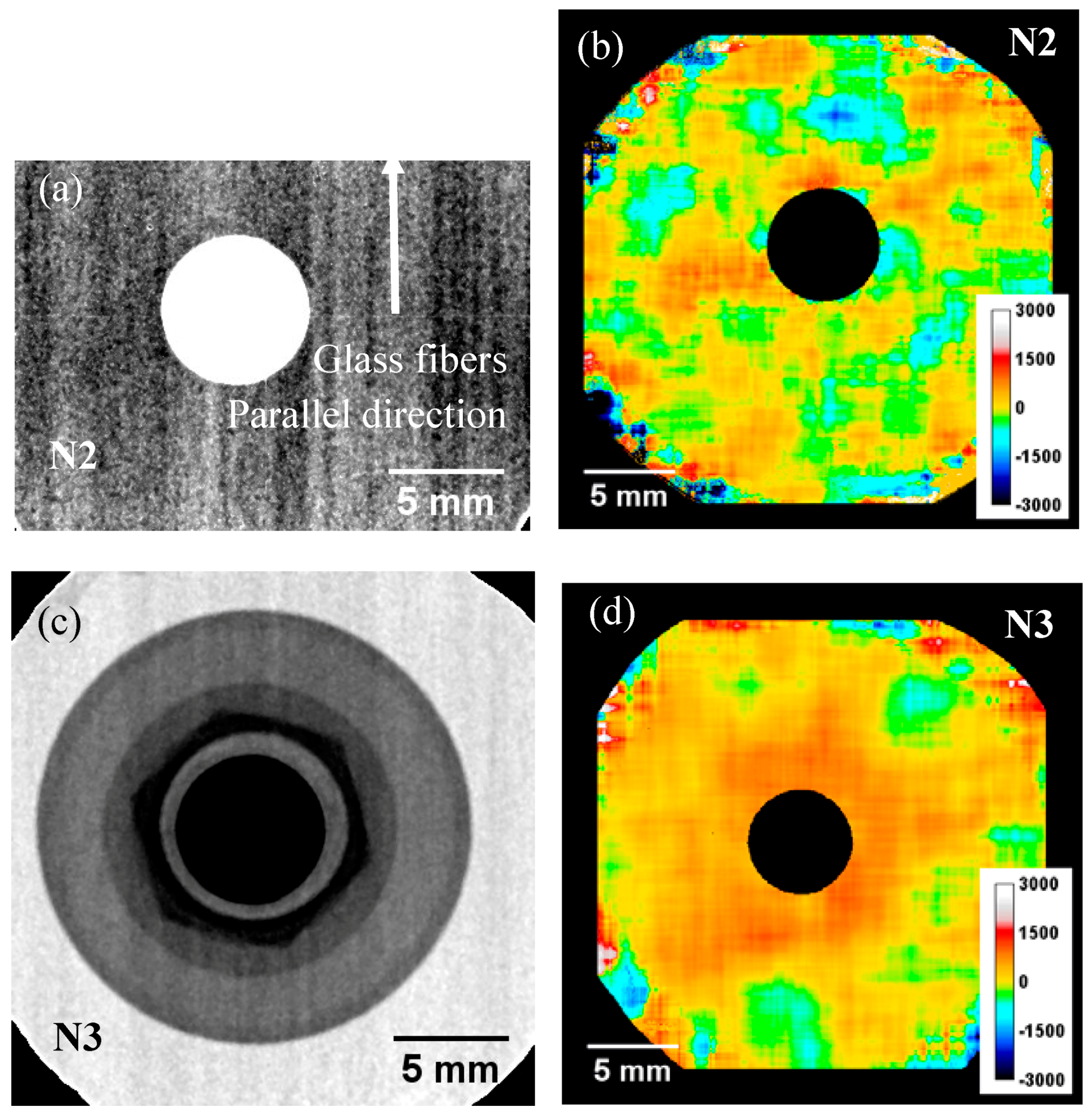
Figure 2a shows a typical transmission image (integrated over a wide range of energies) of Plate P1 with GLARE reinforcement. Most of the contrast in that image is due to the GLARE, with the structure related to the orientation of glass fibers in the GLARE as the aluminium plate itself is quite transparent to neutrons and shows no features in a white-beam radiography. The white spectrum transmission of the bare aluminium plate was measured to be ~94% (Plate P2), while the reinforced plate P1 had ~69% transmission, with most neutron attenuation occurring within the epoxy of the GLARE structure. The strain map reconstructed from the measured transmission spectra for that hole (drilled only, no cold expansion) shown in Figure 2b measured strain values around the hole of −96 ± 240 microstrain averaged over the direction perpendicular to the face of the plate (negative strain apparently is due to imperfect selection of λ0 which for consistency was assumed to be the same for all the holes in each plate). The λ0 value for the strain reconstruction in that plate was taken as an average over the area around drilled hole and was measured to be 4.6710 ± 0.00113 Å. The uncertainty of λ0 in our measurements corresponds to ~240 microstrain, which propagates to all strain maps measured for Plate P1. There is no noticeable correlation of strain with the location of the hole.
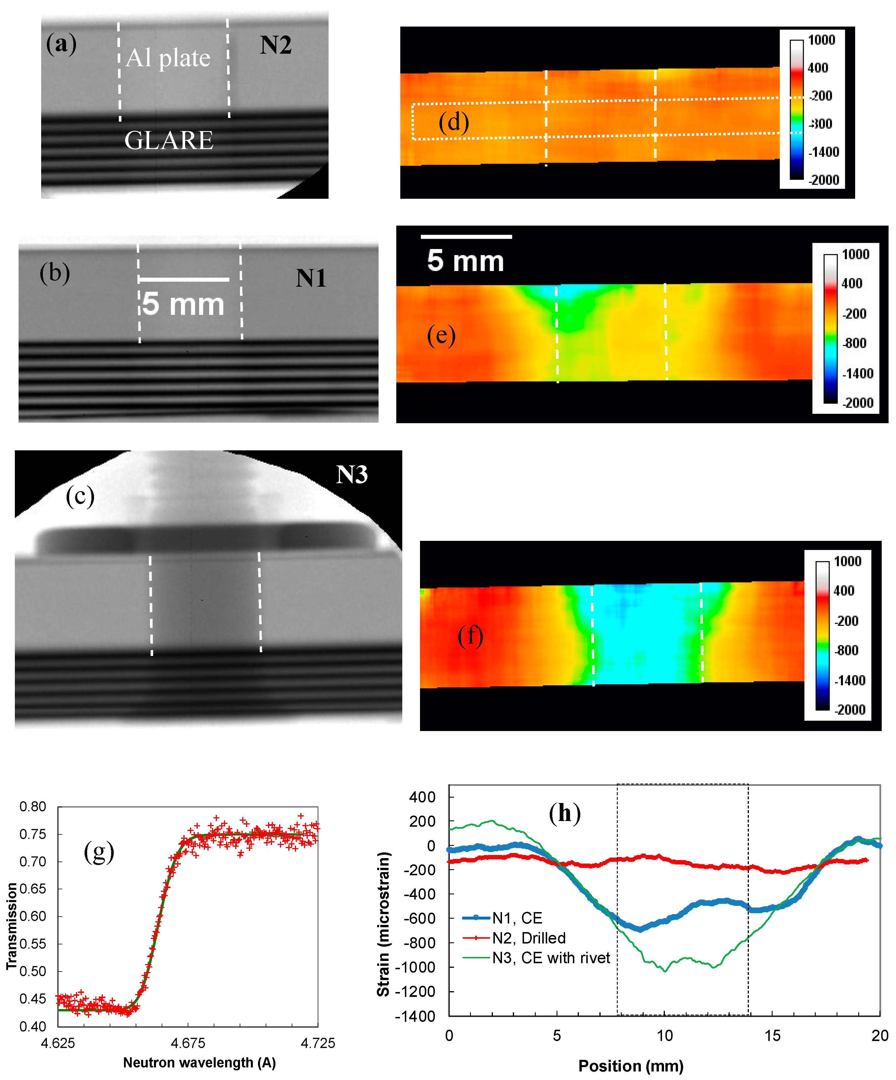
The white beam radiography of the cold-expanded and riveted hole N3 (Figure 2c) shows the location of the washer, the nut and the rivet itself seen as darker areas in that image. The measured transmission spectra for that hole are averaged over the plate and the washers in the area around the hole. This averaging can influence the measured strain values, although in our case the attenuation by the washer was only ~10% compared to the Al plate. Ideally, washer and nut of a different material should be used in this measurement to ensure that there is no overlap of Bragg edges of these two materials. An example, where bcc steel was measured within fcc steel is described in reference [12]. There is tensile strain measured in the area around the hole with an average value of 640 and standard deviation of ±120 microstrain (Figure 2d). Note that the uncertainty of λ0 is larger than the reconstructed strain in Figure 2d due to longer integration time of that image. Therefore the entire strain field could be shifted in that image by ±120 microstrain. The same holes plus hole N1 were also imaged in the “edge-on” configuration, where neutrons propagated parallel to the face of the plate and strain averaged over the plate length in that direction was measured. The white beam radiographies seen in Figure 3a–c have dashed lines indicating the location of the hole in the plate.
The internal structure of GLARE laminate is visible as dark and gray stripes (related to the orientation of glass fibers mixed up with epoxy, which has a much higher scattering cross-section than aluminium, as it contains hydrogen). The strain maps of these three holes in Figure 3d–f clearly demonstrate the difference in strain between the just-drilled hole N2 and the cold-expanded holes N1 and N3 in the same plate. The asymmetry of the cold-expansion procedure, which is related to the direction of manual withdrawal of the tool, is also seen in the holes N1 and N3, exhibiting a V-shaped distribution of strain with opening towards the side where the tool was withdrawn during cold expansion. The horizontal cross-sections through all three holes, shown in Figure 3h demonstrate that compressive strain as high as 1000 microstrain was present in the area adjacent to cold-expanded hole N3. It should be noted that this is the averaged value through the thickness of the plate and therefore strain values can locally be even higher.
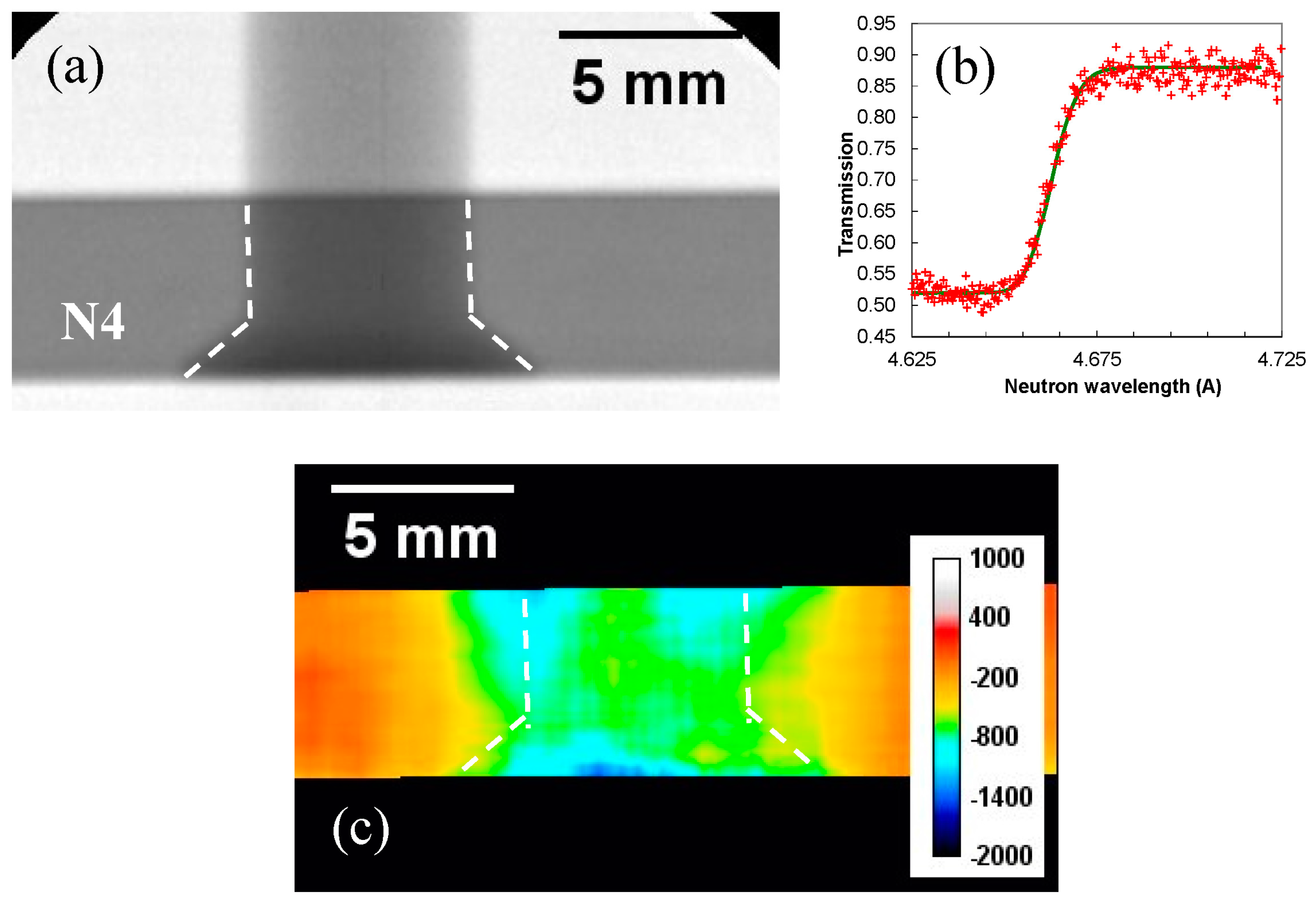
Similar values of strain were also measured for the hole N4, drilled and cold expanded in Plate P3, which had no GLARE reinforcement, Figure 4. Two holes, N6 and N7, produced in Plate P3, were measured simultaneously in “face-on” orientation, Figure 5. There was no specific reason for the different diameters of the two holes, available on the same plate P3. The cross-sections through the areas indicated by dotted rectangles, Figure 5c–e, quantify how the average strain changes across the area adjacent to cold-expanded hole N7, where tensile strain reached values as high as ~2000 microstrain relaxing to nearly unstrained values within ~5 millimeter distance from the hole.

3.1. Asymmetry of Strain around Cold-Expanded Holes

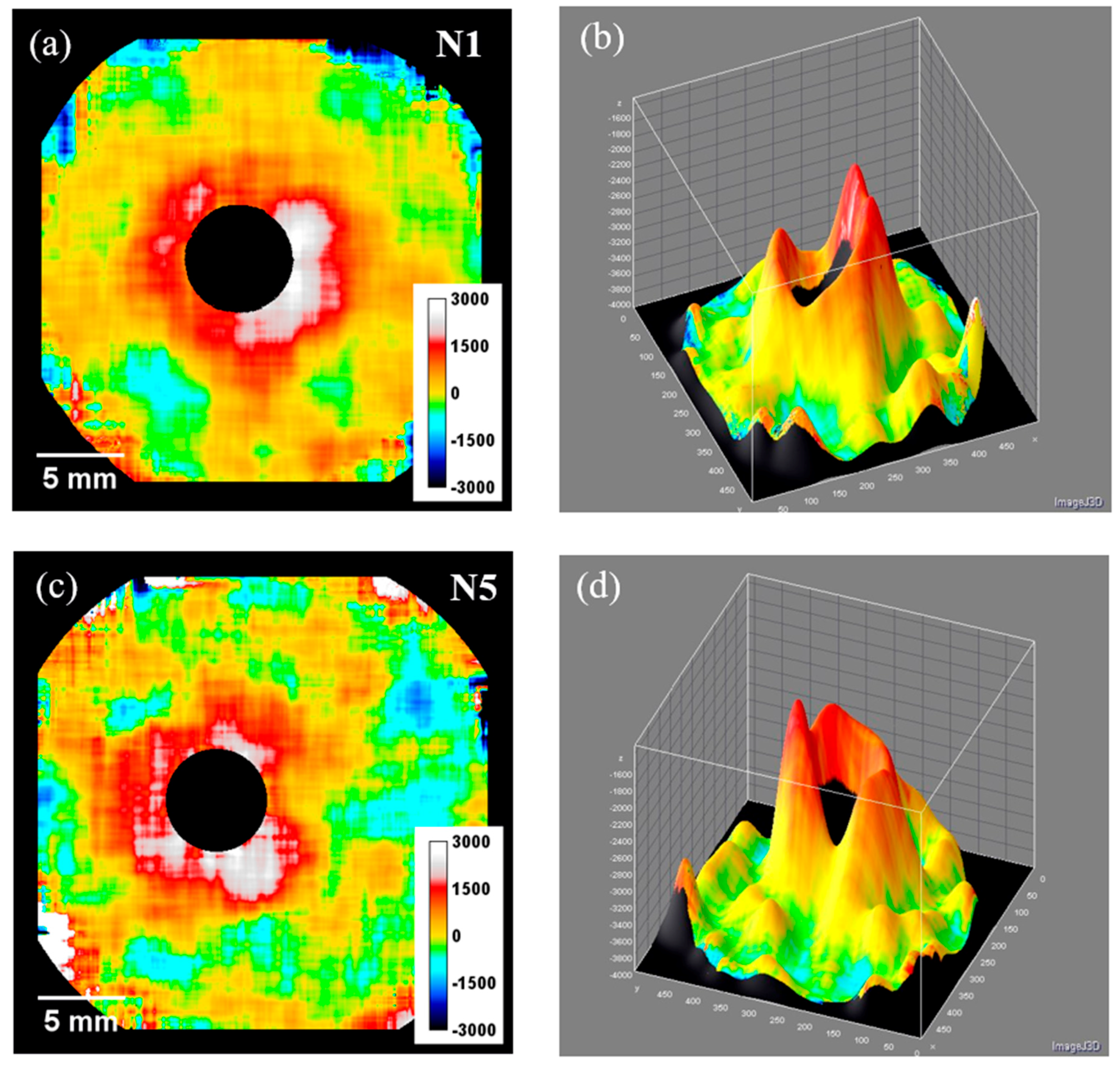
One of the advantages of the presented transmission imaging method is its ability to provide strain maps with sub-mm spatial resolution, thus enabling studies of spatial uniformity of residual strains. Two similarly produced cold-expanded holes in Plate P1 and Plate P2 are compared in Figure 6. The exposure time of hole N5 was shorter, and thus the reconstructed strains were associated with higher uncertainties, with a measured value of 1400 ± 480 microstrain, while strain around hole N1 had nearly the same average value, but with less noise, 1420 ± 250 microstrain. The reconstructed strain values at some regions at the edge of the sample reach extreme and fluctuating values of up to ±3000 microstrain, which is caused by the noise in the experimental data for those areas: the ~2 × 2 mm2 averaging of spectra is reduced to a few pixels, only, close to the edge of the sample. During spectral averaging, only those pixels that contain sample can be used in the analysis, thus limiting the averaging to ~1 × 2 mm2 for the straight edge of the sample and even worse for the outside edge of the circle, as seen in Figure 6 at the edge of the active area. However, the asymmetry of tensile strain is very clearly seen in both strain maps, especially in Figure 6b,d, where strain maps are presented as 3-dimensional surfaces. It is that capability of mapping strain continuously through the entire region of interest, rather than for a few selected points, which makes this technique complementary to other more established non-destructive testing methods, such as neutron diffraction.

3.2. Strain Versus Direction of Glass Fibers in the GLARE Laminate

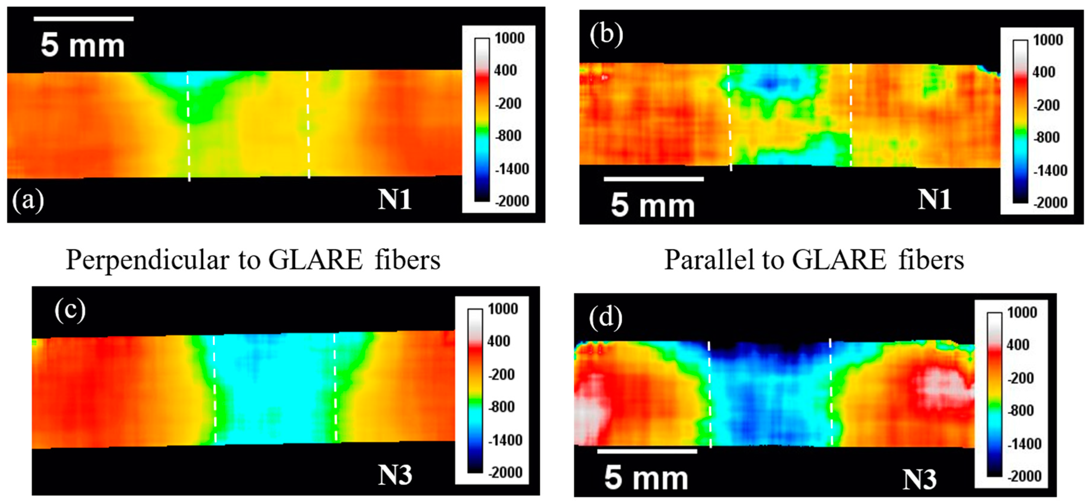
To investigate whether the direction of glass fibers within the reinforcing laminate structure has any influence on the measured residual strain, two samples (with cold-expanded holes N1 and N3 produced in the same Plate P1) were imaged in two orthogonal directions, both in “edge-on” orientation. In one orientation, both plates were mounted in such way that the neutrons were propagating along the plate surface perpendicular to the glass fibers, i.e., perpendicular to the direction marked as “parallel” in Figure 2a (Figure 7a,c for hole N1 and N3, respectively). Then the plates were rotated by 90 degrees such that neutrons were propagating along the plates in the direction parallel to glass fibers in the GLARE structure (Figure 7b,d). The image acquisition time in the latter configuration (parallel to glass fibers) was shorter, resulting in strain maps reconstructed with greater noise, as seen in Figure 7b,d. There is also some difference in the reconstructed strain maps measured for sample N1 and sample N3 when they were mounted in the same orientation with respect to GLARE structure. This can be attributed to the presence of rivet in hole N3 or to the difference in the process of cold expansion, which was done manually and thus was not perfectly reproducible. Within the limitations imposed by these inconsistencies, the results indicate that there were no substantial differences observed between strain maps measured in the direction parallel to GLARE fibers and perpendicular to them, both in the “edge-on” sample orientation.

4. Conclusions

Results presented in this paper demonstrate the capability of energy-resolved neutron imaging to reconstruct maps of residual strain within polycrystalline samples with sub-mm spatial resolution, all from one measurement, across the entire field of view of the detector. The strain values measured around each sample are summarized in Table 2. This technique in no way outperforms or can replace the other more conventional non-destructive strain measurement techniques, based on neutron diffraction, for example. It rather provides complementary information in samples where integration of strain along the direction of the neutron beam is acceptable. In principle, this method allows strain reconstruction with ~100 µm spatial resolution, which is not demonstrated explicitly in this paper, as we had to combine spectra within a ~2 mm area around each 55 µm pixel to compensate for insufficient neutron statistics measured in a single pixel. Brighter neutron sources, stronger neutron-scattering materials compared to aluminium, thicker samples, improved analysis tools—all can potentially increase the spatial resolution of the present method. However, even with the present deficiencies of this technique, it was observed that strain asymmetry around cold-expanded holes can be quantified by this method even for relatively thin (5 and 6.4-mm-thick) aluminium plates. No substantial variation of strain averaged in the direction along the reinforcement glass fibers and in the direction perpendicular to them (both in “edge-on” sample orientation) was observed in the present experiment. No difference was found for the strains normal to the face of the plate (through the sample direction) for plates with and without GLARE reinforcement.

Acknowledgments

Authors would like to acknowledge the generous donation of the Vertex FPGA and ISE design suite by Xilinx Inc. of San Jose, California, through their Xilinx University Program. The detector used in these experiments was developed in a collaboration between UC Berkeley and Nova Scientific, partially funded by the US Department of Energy under STTR grant Nos. DE-FG02-07ER86322, DE-FG02-08ER86353 and DE-SC0009657. The Timepix readout was developed within the Medipix collaboration. MEF is grateful for funding from the Lloyd’s Register Foundation, a charitable foundation helping protect life and property by supporting engineering-related education, public engagement, and the application of research.

Author Contributions

The experiments and the manuscript preparation were performed in collaboration between all the authors. The samples were prepared by M.E.F., the measurements were performed by A.S.T., W.K., J.F.K. and A.M.P., the data was analyzed by A.S.T., W.K., R.S.R. and M.E.F. and the manuscript was discussed and edited by all the authors.

Conflicts of Interest

The authors declare no conflict of interest.

References

  1. Mocko, M.; Muhrer, G.; Kelsey, C.T.; Duran, M.A.; Tovesson, F. Experimental measurement of the neutron time emission spectra at the Manuel Lujan Jr. neutron scattering center. Nucl. Instrum. Methods Phys. Res. Sect. A 2011, 632, 101–108. [Google Scholar] [CrossRef]
  2. Bilheux, H.; Herwig, K.; Keener, S.; Davis, L. Overview of the conceptual design of the future VENUS neutron imaging beam line at the Spallation Neutron Source. Phys. Procedia 2015, 69, 55–59. [Google Scholar] [CrossRef]
  3. Minniti, T.; Kockelmann, W.; Burca, G.; Kelleher, J.F.; Kabra, S.; Zhang, S.Y.; Pooley, D.E.; Schooneveld, E.M.; Mutamba, Q.; Sykora, J.; et al. Materials analysis opportunities on the new neutron imaging facility IMAT@ISIS. J. Instrum. 2016, 11, C03014. [Google Scholar] [CrossRef]
  4. Matsumoto, Y.; Segawa, M.; Kai, T.; Shinohara, T.; Nakatani, T.; Oikawa, K.; Hiroi, K.; Su, Y.H.; Hayashida, H.; Parker, J.D.; et al. Recent Progress of Radiography and Tomography at the Energy-resolved Neutron Imaging System RADEN. Phys. Procedia 2017, 88, 162–166. [Google Scholar] [CrossRef]
  5. Parker, J.D.; Hattori, K.; Fujioka, H.; Harada, M.; Iwaki, S.; Kabuki, S.; Kishimoto, Y.; Kubo, H.; Kurosawa, S.; Miuchi, K.; et al. Neutron imaging detector based on the µPIC micro-pixel chamber. Nucl. Instrum. Methods Phys. Res. Sect. A 2013, 697, 23–31. [Google Scholar] [CrossRef]
  6. Tremsin, A.S.; Vallerga, J.V.; McPhate, J.B.; Siegmund, O.H.W. Optimization of high count rate event counting detector with Microchannel Plates and quad Timepix readout. Nucl. Instrum. Methods Phys. Res. Sect. A 2015, 787, 20–25. [Google Scholar] [CrossRef]
  7. Santisteban, J.R.; Edwards, L.; Steuwer, A.; Withers, P.J. Time-of-flight neutron transmission diffraction. J. Appl. Crystallogr. 2001, 34, 289–297. [Google Scholar] [CrossRef]
  8. Vogel, S. A Rietveld-Approach for the Analysis of Neutron Time-of-Flight Transmission Data. Ph.D. Thesis, Christian Albrechts Universität, Kiel, Germany, 2000. [Google Scholar]
  9. Sato, H.; Watanabe, K.; Kiyokawa, K.; Kiyanagi, R.; Hara, K.Y.; Kamiyama, T.; Furusaka, M.; Shinohara, T.; Kiyanagi, Y. Further improvement of the RITS code for pulsed neutron Bragg-edge transmission imaging. Phys. Procedia 2017, 88, 322–330. [Google Scholar] [CrossRef]
  10. Song, G.; Lin, J.Y.Y.; Bilheux, J.C.; Xie, Q.; Santodonato, L.J.; Molaison, J.J.; Skorpenske, H.D.; Dos Santos, A.M.; Tulk, C.A.; An, K.; et al. Characterization of Crystallographic Structures Using Bragg-Edge Neutron Imaging at the Spallation Neutron Source. J. Imaging 2017, 3, 65. [Google Scholar] [CrossRef]
  11. Sun, T.; Tremsin, A.S.; Roy, M.J.; Hofmann, M.; Prangnell, P.B.; Withers, P.J. Investigation of residual stress distribution and texture evolution in AA7050 stationary shoulder friction stir welded joints. Mater. Sci. Eng. A 2018, 712, 531–538. [Google Scholar] [CrossRef]
  12. Tremsin, A.S.; Yau, T.Y.; Kockelmann, W. Non-destructive examination of loads in regular and self-locking Spiralock® threads through energy-resolved neutron imaging. Strain 2016, 52, 548–558. [Google Scholar] [CrossRef]
  13. Malamud, F.; Santisteban, J.R. Full-pattern analysis of time-of-flight neutron transmission of mosaic crystals. J. Appl. Cryst. 2016, 49, 348–365. [Google Scholar] [CrossRef]
  14. Tremsin, A.S.; Vogel, S.C.; Mocko, M.; Bourke, M.A.M.; Yuan, V.; Nelson, R.O.; Brown, D.W.; Feller, W.B. Non-destructive studies of fuel rodlets by neutron resonance absorption radiography and thermal neutron radiography. J. Nucl. Mater. 2013, 440, 633–646. [Google Scholar] [CrossRef]
  15. Festa, G.; Perelli Cippo, E.; Di Martino, D.; Cattaneo, R.; Senesi, R.; Andreani, C.; Schooneveld, E.; Kockelmann, W.; Rhodes, N.; Scherillo, A.; et al. Neutron resonance transmission imaging for 3D elemental mapping at the ISIS spallation neutron source. J. Anal. At. Spectrom. 2015, 30, 745–750. [Google Scholar] [CrossRef] [Green Version]
  16. Kai, T.; Maekawa, F.; Oshita, H.; Sato, H.; Shinohara, T.; Ooi, M.; Harada, M.; Uno, S.; Otomo, T.; Kamiyama, T.; et al. Visibility estimation for neutron resonance absorption radiography using a pulsed neutron source. Phys. Procedia 2013, 43, 111–120. [Google Scholar] [CrossRef]
  17. Kamiyama, T.; Ito, J.; Noda, H.; Iwasa, H.; Kiyanagi, Y.; Ikeda, S. Computer tomography thermometry—An application of neutron resonance absorption spectroscopy. Nucl. Instrum. Methods Phys. Res. Sect. A 2005, 542, 258–263. [Google Scholar] [CrossRef]
  18. Tremsin, A.S.; Kockelmann, W.; Pooley, D.E.; Feller, W.B. Spatially resolved remote measurement of temperature by neutron resonance absorption. Nucl. Instrum. Methods Phys. Res. Sect. A 2015, 803, 15–23. [Google Scholar] [CrossRef]
  19. Tremsin, A.S.; Losko, A.S.; Vogel, S.C.; Byler, D.D.; McClellan, K.J.; Bourke, M.A.M.; Vallerga, J.V. Non-contact measurement of partial gas pressure and distribution of elemental composition using energy-resolved neutron imaging. AIP Adv. 2017, 7, 015315. [Google Scholar] [CrossRef]
  20. Shinohara, T.; Hiroi, K.; Su, Y.; Kai, T.; Nakatani, T.; Oikawa, K.; Segawa, M.; Hayashida, H.; Parker, J.D.; Matsumoto, Y.; et al. Polarization analysis for magnetic field imaging at RADEN in J-PARC/MLF. J. Phys. 2017, 862, 012025. [Google Scholar] [CrossRef]
  21. Tremsin, A.S.; Perrodin, D.; Losko, A.S.; Vogel, S.C.; Bourke, M.A.M.; Bizarri, G.A.; Bourret, E.D. Real-time crystal growth visualization and quantification by energy-resolved neutron imaging. Sci. Rep. 2017, 7, 46275. [Google Scholar] [CrossRef] [PubMed]
  22. Iwase, K.; Sato, H.; Harjo, S.; Kamiyama, T.; Ito, T.; Takata, S.; Aizawa, K.; Kiyanagi, Y. In situ lattice strain mapping during tensile loading using the neutron transmission and diffraction methods. J. Appl. Crystallogr. 2012, 45, 113–118. [Google Scholar] [CrossRef]
  23. Ramadhan, R.S.; Syed, A.K.; Tremsin, A.S.; Kockelmann, W.; Dalgliesh, R.; Chen, B.; Parfitt, D.; Fitzpatrick, M.E. Mapping residual strain induced by cold working and by laser shock peening using neutron transmission spectroscopy. Mater. Des. 2018, 143, 56–64. [Google Scholar] [CrossRef]
  24. Tremsin, A.S.; Ganguly, S.; Meco, S.; Pardal, G.R.; Shinohara, T.; Feller, W.B. Non-destructive studies of dissimilar metal welds by energy resolved neutron imaging. J. Appl. Crystallogr. 2016, 49, 1130–1140. [Google Scholar] [CrossRef] [PubMed]
  25. Syed, A.K.; Zhang, X.; Moffatt, J.E.; Maziarz, R.; Castelletti, L.; Fitzpatrick, M.E. Fatigue performance of bonded crack retarders in the presence of cold worked holes and interference-fit fasteners. Int. J. Fatigue 2017, 105, 111–118. [Google Scholar] [CrossRef]
  26. Cook, R.; Holdway, P. Residual stresses induced by hole cold expansion. Trans. Eng. Sci. 1993, 2, 91–100. [Google Scholar]
  27. Syed, A.K.; Fitzpatrick, M.E.; Moffatt, J.E. Effect of Thermal Residual Stresses on Bonded Structures Containing Cold Expanded and Bolted Holes. Adv. Mater. Res. 2014, 996, 682–687. [Google Scholar] [CrossRef]
  28. Santisteban, J.R.; Daymond, M.R.; James, J.A.; Edwards, L. ENGIN-X: A third-generation neutron strain scanner. J. Appl. Cryst. 2006, 39, 812–825. [Google Scholar] [CrossRef]
  29. Tremsin, A.S. High resolution neutron counting detectors with microchannel plates and their applications in neutron radiography, diffraction and resonance absorption imaging. Neutron News 2012, 23, 35–38. [Google Scholar] [CrossRef]
  30. Daymond, M.R.; Bourke, M.A.M.; Von Dreele, R.B.; Clausen, B.; Lorentzen, T.J. Use of Rietveld refinement for elastic macrostrain determination and for evaluation of plastic strain history from diffraction spectra. J. Appl. Phys. 1997, 82, 1554–1562. [Google Scholar] [CrossRef]
  31. Tremsin, A.S.; McPhate, J.B.; Steuwer, A.; Kockelmann, W.; Paradowska, A.M.; Kelleher, J.F.; Vallerga, J.V.; Siegmund, O.H.W.; Feller, W.B. High-resolution strain mapping through time-of-flight neutron transmission diffraction with a microchannel plate neutron counting detector. Strain 2012, 48, 296–305. [Google Scholar] [CrossRef]
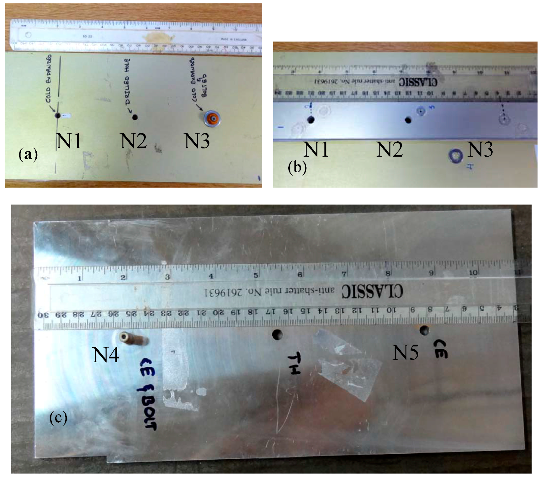
Figure 1. Photograph of two aluminium plates with holes measured in the present experiment. (a,b) Front and back sides of Plate P1. A GLARE structure was attached to this plate before the holes were drilled; (c) Plate P2 had no GLARE structure attached. The characteristics of the holes are described in Table 1. The aluminum plates were 5 mm thick.
Jimaging 04 00048 g001
Figure 2. (a) White-spectrum transmission image of area around hole N2. The asymmetry in the GLARE structure (related to the orientation of glass fibers) is clearly visible as vertical dark/gray stripes; (b) Map of strain values (in the through-plate direction) measured around hole N2. Strain reconstructed by fitting the edge function into (111) Bragg edge spectrum accumulated around each pixel (running average within ~2 mm area); (c) White spectrum transmission image of hole N3 with bolted rivet. Washer, nut and rivet heads are seen as dark areas around the hole; (d) Map of strain values reconstructed from (111) Bragg edge.
Jimaging 04 00048 g002
Figure 3. (ac) White spectrum transmission images of samples in edge-on orientation for drilled, cold-expanded and cold-expanded with rivet holes, N2, N1 and N3, respectively. The 6 pairs of GLARE layers are seen as dark sheets in the image. Dashed lines indicate the location of the hole; (df) Strain maps in the direction parallel to the plate surface reconstructed from the measured data. The dashed rectangle in (d) indicates the location of the area for the cross-section through the strain maps shown in (h); (g) The (111) Bragg edge spectrum measured for the plates in this orientation (crosses) and the fitted curve; (h) Cross sections through the images (df). The gray area in (h) shows the approximate location of the holes.
Jimaging 04 00048 g003
Figure 4. (a) White spectrum image of riveted cold-expanded hole N4 (edge-on view); (b) The measured (111) Bragg edge used for the reconstruction of strain distribution across the sample shown in (c).
Jimaging 04 00048 g004
Figure 5. Residual strain maps reconstructed for holes N6 and N7 in Plate P3, which were measured simultaneously. (a) Measured (111) Bragg edge (crosses) and fitted function (solid line) used for the measurement of edge wavelength; (b) Reconstructed strain map around the holes; (ce) Cross-sections through the areas shown by dotted rectangles in image (b).
Jimaging 04 00048 g005
Figure 6. Reconstructed strain maps around cold-expanded holes N1 (Plate P2, shown in (a,b)) and N5 (Plate P2, shown in (c,d)). The asymmetry of strain around a hole is better seen in (b,d) representation of same data as in (a,c).
Jimaging 04 00048 g006
Figure 7. Reconstructed strain maps of cold-expanded holes N1 and N3 measured in two perpendicular directions: in (a,c) strain is in the direction along the glass fibers in the GLARE structure marked as “parallel” in Figure 2a; (b,d) strain in the perpendicular direction relative to figures (a,c). The GLARE reinforcement was at the bottom side of each sample. No substantial difference was observed for the strain maps in these two orthogonal directions.
Jimaging 04 00048 g007
Table 1. Characteristics of holes measured in the present experiment. All holes were first drilled in aluminium plates. The GLARE structure attached to samples N1–N3 consisted of 6 pairs of Al and fiberglass layers.
Hole NPlate NCold-ExpandedGLARERivetPlate Thickness, mmHole Ø/mm
N1P1-5~6
N2P1--5~6
N3P15~6
N4P2-5~6
N5P2--5~6
N6P3---6.4~2.8
N7P3--6.4~7.7
Table 2. Summary of approximate peak residual strain values (με) measured within the samples.
Drilled (N2, N6)Cold-Expanded, No Rivet, (Face-on)Cold-Expanded, No Rivet, (Edge-on)Cold-Expanded, with Rivet, (Face-on)Cold-Expanded, with Rivet, (Edge-on)
~0 ± 2401500 ± 240 (N1, N5) 2000 ± 240 (N7)−700 ± 240 (N1)800 ± 240 (N3)−1000 ± 240 (N3, N4)