Abstract
Carbon Fiber Composites (CFCs) recycling has received increasing interest by the composites industry, but it is still in its early stages as an industry. There are two primary challenges that need to be addressed in order to achieve full property retention during CFC recycling: (1) the ability to recover the fiber content without property loss; and (2) conversion of the recycled, short fiber material back into high-performance CFC structures. The ability to manufacture high fiber volume fraction CFCs with end-of-life products would provide an opportunity to reduce material cost and lifetime-embodied energy. In this paper, recycled, short carbon fibers are processed via solvolysis and converted into high-performance CFCs with fiber volume fraction of ~50% and excellent composite property retention. This is enabled through alignment of the discontinuous, recycled fiber feedstock using the Tailorable universal Feedstock for Forming (TuFF) process. The paper introduces the necessary steps to process the fibers in the wet-laid process and explores the resulting mechanical and microstructural properties. The importance of incoming fiber surface quality and the effect of surface contamination from residue left by the recycling process on both the TuFF process and final composite properties is discussed in detail. A pyrolytic process has been adopted to remove the residue that is a by-product of the recycling process from the incoming recycled fiber surface. The approach presents a promising pathway for the recycling of high-performance CFCs.
1. Introduction
Carbon Fiber Composites (CFC) have superior specific mechanical properties enabling lightweight structural applications in many areas such as automotive, wind energy, aeronautics, aviation and consumer goods applications [1]. The demand for carbon fibers (CFs) has been increasing since 2010 from 51,000 tons to 124,000 tons in 2021 and is expected to reach 147,500 tons in 2023 [2]. As a result of this expected increase in demand, composite waste volume is expected to increase significantly. In the wind power industry, due to the increase in blades that are serviced out, the amount of end-of-life waste is expected to increase by 14% between 2020 and 2050. Even though the wind power industry is mostly dominated by glass fiber composites, similar growth rates are to be expected for the aerospace industry, where CFs present a higher market share. Furthermore, a supply deficit of virgin CF (vCF) opens up new opportunities if recycled CFCs can be produced with mechanical properties similar to the virgin material [3].
Typically, the CF recycling process is performed by following two steps. First, fiber reclamation/recovery through pyrolysis, solvolysis, and pre-solvolysis steps extract the fibers from the polymer [4,5]. These processes might affect fiber strength and stiffness, eliminates any sizing on the surface and often leaves a small amount of residue on the fiber surface. Pyro gasification has been used to clean fibers but result in significant fiber strength degradation [6,7,8]. Second, the reclamation/recovery step is followed by reformatting of the recycled fibers into intermediate material formats (compounds, dry fabric or prepreg) followed by conventional part manufacturing. Currently, a large portion of CFCs are recycled by shredding and the recovered short recycled CFs (rCFs) are processed into Sheet Molding Compounds (SMC) or nonwovens [9,10]. The properties from these recovered/recycled materials are significantly lower than those of parts made from virgin materials, mainly due to the low fiber volume fraction (FVF) and short fiber length [11]. Material formats typically produced using rCFs are not suitable for high-performance, load-bearing components. A 2011 review paper by Pimenta [12] tabulates composite properties from recycled fibers for a number of processes with a reported peak strength of 422 MPa and peak modulus of 80 MPa using compression molding at 44% FVF. Data by Longana using their HiPerDiF alignment process [13] shows strength and stiffness of 460 MPa and 52 GPa at 28.3% FVF, respectively. FVF and property translation needs to be significantly improved to allow the use of recycled fibers in structural applications.
The Tailorable universal Feedstock for Forming (TuFF) technology produces highly aligned short fiber preforms allowing high fiber volume fraction parts with full property translation that is comparable to continuous fiber composites [14,15]. This creates the potential for a paradigm shift in recycling of composites. Recycled fibers are often recovered in discontinuous form and the TuFF process can produce high-performance parts from these short, recycled fibers. Fiber strength retention, good fiber adhesion to the matrix, fiber length control and the ability to disperse the fiber in a fluid are key properties to produce high-performance TuFF composites [16,17]. This paper is evaluating solvolysis processed recycled fibers from Vartega, a key US supplier of recycled carbon fibers, where the fibers maintain full mechanical properties. An additional cleaning step is used on the fibers to enable good fiber dispersion in the TuFF process and the resulting composite coupons at ~50% FVF are evaluated for microstructural quality and mechanical properties.
2. Material and Method
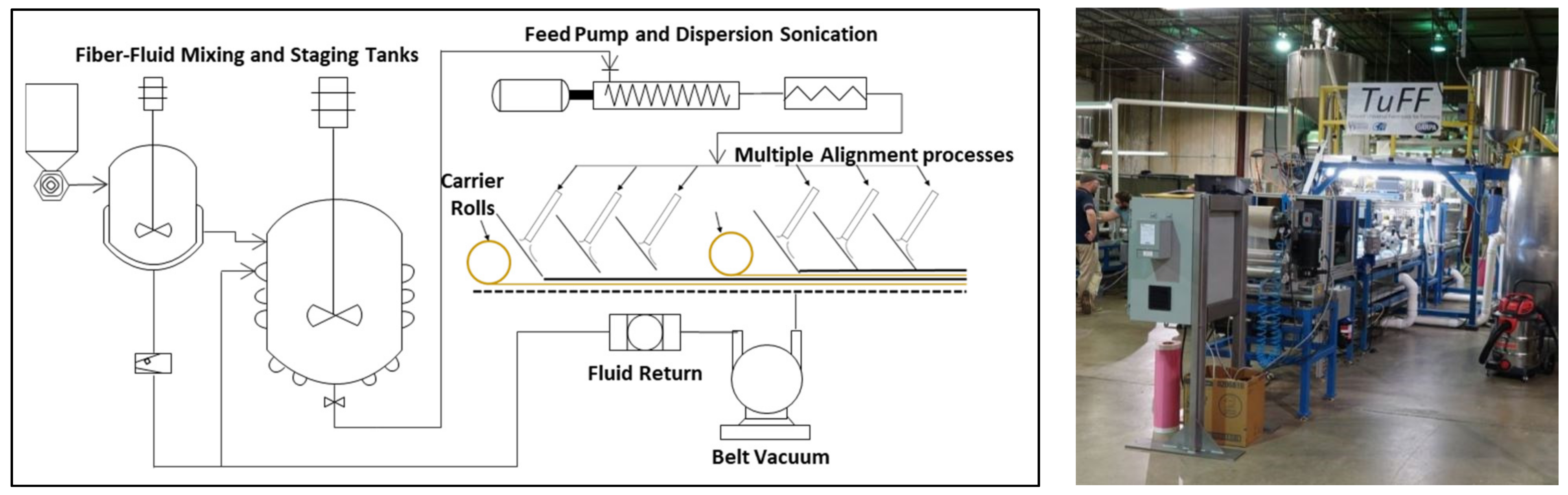
The TuFF wet-laid process [18,19] uses a fluid reservoir containing suspended fibers connected to a deposition surface over a moving belt. A schematic and a photo of the alignment process is shown in Figure 1. The short fibers can be any type of fiber or combination of fibers (carbon fibers, glass fibers, ceramic fibers, metal fibers, polymer fibers, natural fibers, recycled fibers, and nanofibers) with different aspect ratios if desired. Fiber dispersion at the filament level is critical to create a defect-free TuFF sheet. The fibers are spread uniformly on the sheet surface and deposited on the porous belt. Fibers are highly aligned at the deposition belt surface, fluid is extracted through the porous belt using a vacuum, and the fiber material is stabilized. The deposition sheet can be rotated to position fibers at a wide range of widths and angles with respect to the belt travel direction to create tows, tapes, and sheets. Previous studies have demonstrated full property translation in TuFF CFCs with virgin, 3 mm-long CFs, and thermoplastic matrix [14,15]. This work explores the use of rCFs and its challenges creating full property translation using the TuFF process.

Figure 1.
Schematic and photo of the short fiber alignment process.
The current study compares results of TuFF prepreg made from vCF and rCF with continuous CF prepreg. Discontinuous vCF (T800H with 50C sizing, 1% by wt.) was procured with nominal length of 3 mm including a small number of the continuous fiber for strength testing. T800 rCFs are procured from Vartega, Inc. using a proprietary solvolysis process to reclaim the CFs from waste prepreg. The authors have no additional information about the Vartega process but a recent review paper by Butenegro et al. [20] identifies a number of chemical recycling methods recovering carbon fibers from composite waste products with no strength degradation observed. Fiber diameters were measured for all three fiber materials using microscopy and confirmed 5.0 µm average diameter for the intermediate modulus fiber showing no significant dimensional change of the fiber. For all TuFF samples, a 72 gsm epoxy resin film from Axiom Materials (Axiom AX5201 FR-1) is used for film impregnation of the TuFF material, which is then autoclave processed to fabricate the composite samples.
3. Recycled Fiber Cleaning Process
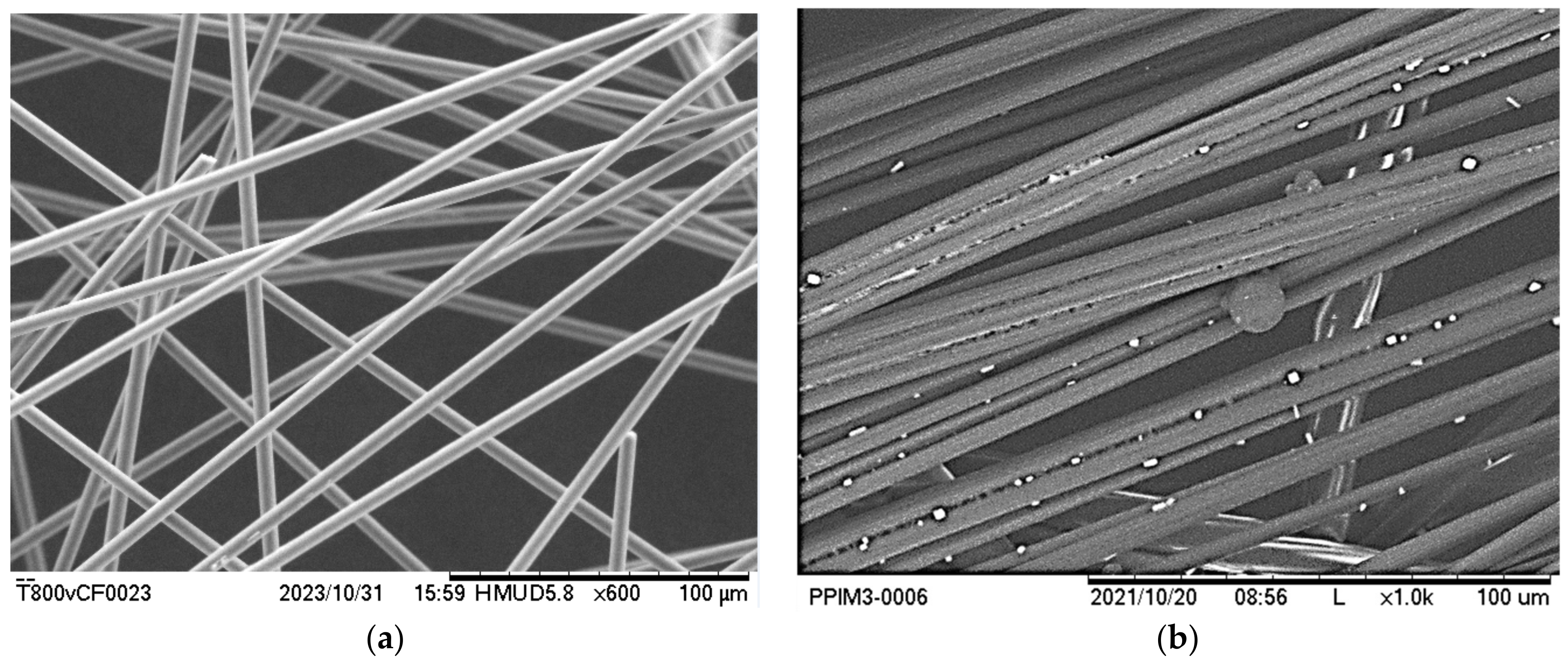
The recycling step often leaves a small amount of residue on the fiber surface, which binds individual fibers together. This is not a significant issue when the rCFs are used in compounds or non-woven mats where fiber agglomerates are acceptable. In contrast, the TuFF process requires full dispersion of all fibers as alignment occurs at the individual fiber level. The amount, location and material type of the left-over residue will depend on the CFC material and recycling process used. Figure 2 compares the fiber surfaces of vCFs and rCFs using a scanning electron microscopic (SEM). Both fiber samples are dispersed in water, mixed using manual stirring and dried prior to evaluation. The vCF sample shows the randomized orientation of all fibers as well as good separation of the fibers. In contrast, the rCF sample has not dispersed well, with a significant number of parallel fibers observed. These parallel fibers are held together in localized regions by residue remaining on the fibers after the solvolysis process.
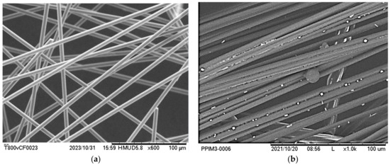
Figure 2.
SEM of (a) vCFs showing random orientation indicating good separation (left, 600×) and (b) rCF fibers with residue and bundling of fiber agglomerates (right, 1000×).
A proposed cleaning step is designed for our specific material/recycling process, but the approach can be applied to other materials and recycling processes (and even integrated into any standard pyrolysis cycle). The cleaning step, described below, leverages that CFs do not degrade under an inert environment until very high temperatures [21] while most polymer residue degrades under elevated temperatures [22,23,24,25,26,27].
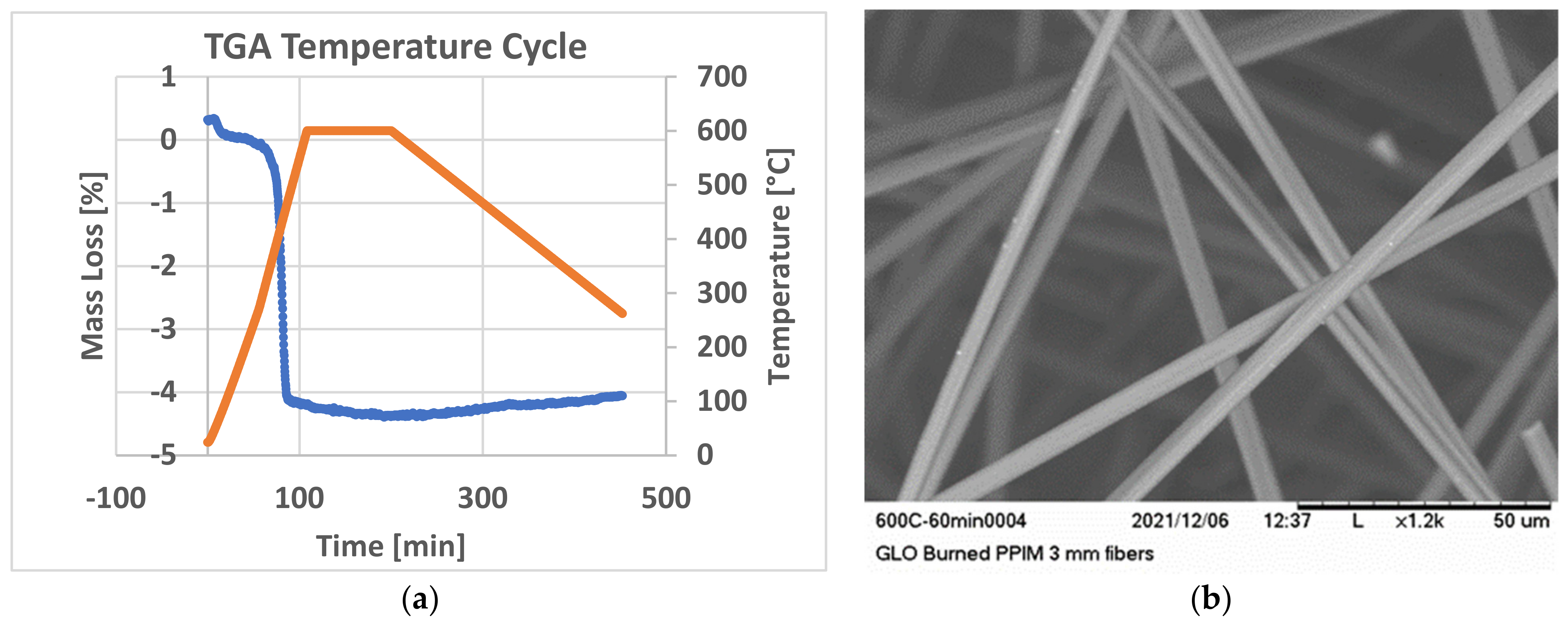
Non-isothermal thermogravimetric analysis (TGA) is conducted on the rCF using a heating rate of 5 °C per minute under an inert environment (nitrogen) to evaluate the amount as well as the degradation temperature of the residue remaining on a sampling of the rCF. The inert environment ensures no degradation to the CFs. For the as received rCFs from Vartega, ~4% residue is observed with degradation occurring at around 400 °C. A cleaning process cycle is designed to safely eliminate the residue using the results obtained in the TGA testing. The rCF is placed in a Carbolite GLO furnace heated to 600 °C (rate 5 °C per minute) with a 90-min dwell followed by a controlled cooling to 300 °C.
The cycle is replicated in the TGA (Figure 3a) and shows no significant weight loss during the dwell and cooling process. The resulting cleaned rCF (cCF) batch is dispersed in water and SEM pictures taken (Figure 3b). These fibers are seen to be randomly oriented without any visual residue, indicating that fibers are dispersed at the filament level. This cleaning cycle used for other rCFs will depend on the polymer composition and recycling process used to recover the rCFs. Further optimization of the dwell cycle is also possible, reducing cycle time and energy cost, but is not part of this study.

Figure 3.
(a) TGA data shows residue weight loss (blue line) at ~400 °C without weight loss during dwell (orange line) and (b) SEM of GLO furnace processed (60 min dwell at 600 °C) cleaned fibers showing no residue after and a random microstructure (right, 1200×).
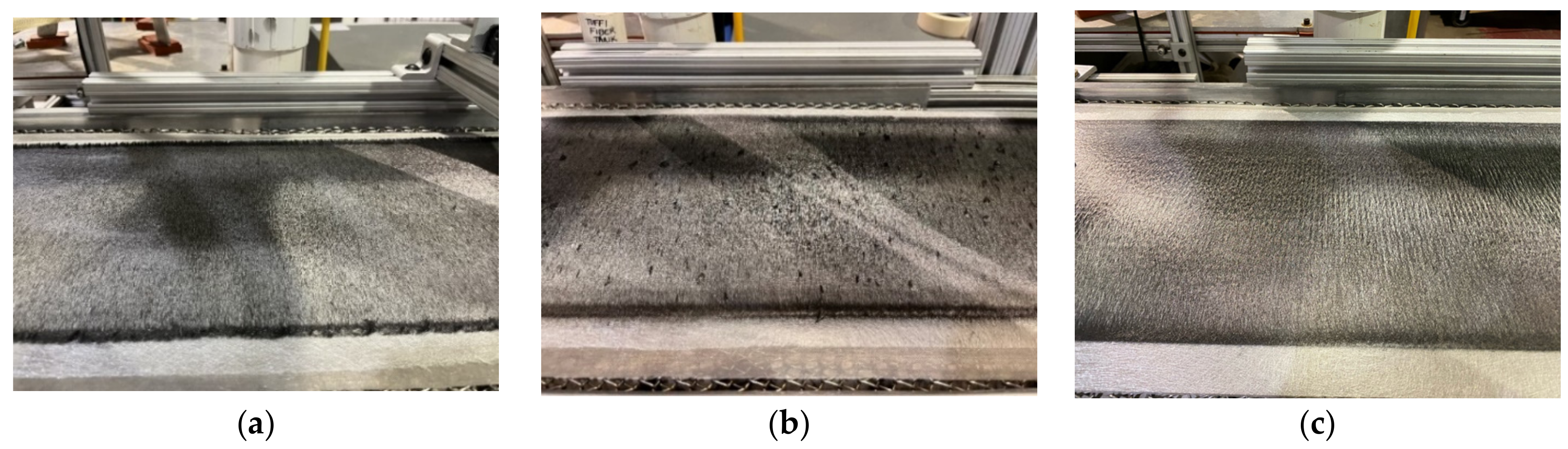
vCFs with sizing, rCFs and cCF s are processed in the TuFF production line to make TuFF sheets of aligned fibers (Figure 4). vCF and cCF show only a small amount of fiber agglomerates while the rCF material has significant agglomerates (dark region in sheets). This demonstrates that the cleaning step is successful in removing most of the residue and allows good dispersion of the cCFs. It is noted that a small number of agglomerates are still observed in the cCF TuFF sheets, but product quality is deemed to be sufficient for further processing.
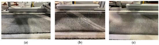
Figure 4.
(a) vCF (left), (b) rCF (middle), and (c) cCF (right) aligned TuFF sheets with the rCF material having significant amount of fiber agglomerates.
4. Property Evaluation during rCF TuFF Processing
The CFC mechanical properties depend not only on the alignment quality establishing the microstructure and thus packing efficiency, but also on the fiber strength/stiffness, adhesion, and fiber geometry properties. The recycling and cleaning step can affect and even degrade these properties as the CFs go through the multiple processing steps. This work is not proposing any process improvements but evaluates the important material property changes of the vCF, rCF, and cCF for comparison purposes. This provides insight into potential mechanisms explaining any property reduction in the cCF TuFF composite.
4.1. Fiber Strength Tests
The vCF, rCF, and cCF fiber strengths are measured to assess any degradation resulting from the recycling processing. Longer rCF and cCF are processed in the same solvolysis and cleaning steps. A Diastron robotic single filament tensile testing apparatus is used following the ASTM C1557-20 Standard Test Method. Load is measured using a 2.5 Newton load cell with a resolution of 0.5 mN. Single filaments are laid across plastic end tabs arrayed in a special cassette that ensures a 12 mm gauge length. Once the filaments have been aligned in the tray, a small amount of room temperature curing epoxy is applied to each end of the filament fixing it in place. To carry out the tensile testing, the tray of fibers (20 fibers) is placed in the Diastron instrument, where a robotic arm picks up each sample and places it in the testing grips. Displacement and load are recorded during the test and tensile strength is calculated based on parameters such as filament diameter, gauge length, and instrument compliance.
Figure 5 summarizes the average tensile strength and standard deviation of the tested fibers. The results show that there is minimal reduction in tensile strength of the recycled and GLO oven cleaned fibers compared to the virgin fibers. Measured virgin fiber strength is within a standard deviation of the manufacturer reported value. Average strength of cCF s is 98% of the vCFs with the coefficient of variation of 12% for the cCF and 15% for the vCF, which are significantly larger than the respective measured strength reduction. The data suggests that there is no negative impact on fiber strength for either the recycling or cleaning process.
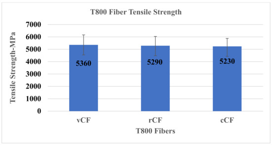
Figure 5.
Average tensile strengths of vCF, rCF, and cCF are all within less than one standard deviation showing minimum or no degradation occurred during the recycling process.
4.2. Interfacial Shear Strength Tests
Interfacial Shear Strength (IFSS) tests are performed to determine the fiber resin adhesion quality of the fibers subjected to the various processing conditions [28,29,30]. Full translation of properties from the discontinuous fiber to the composite requires good adhesion between the fiber and the resin. Low adhesion of the fiber-resin interface may result in low strength properties in the manufactured composite. For this effort, five test samples are produced using the Textechno Fimabond and tested in the Textechno Favimat devices with the fiber pullout fixture. All tests are conducted at 0.1 mm/min extension rate. To determine the IFSS, the fiber embedded length is measured using post-failure images captured by a Hitachi TM3030 tabletop SEM. Fiber resin adhesion properties of the tested vCF, rCF, and cCF with the Axiom epoxy resin are shown in Figure 6 and are essentially equivalent within the bounds of experimental uncertainty.
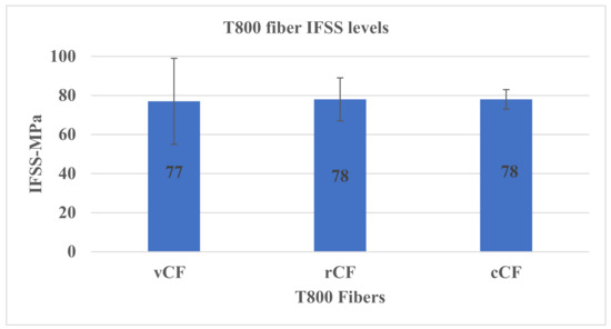
Figure 6.
IFSS data shows no measurable adhesion differences with the processed fibers.
From these results, it is clear that the recycling and cleaning process does not adversely affect fiber adhesion performance for this particular combination of resin and fiber. We speculate that in this instance the primary mechanism for adhesion is mechanical interlocking between the resin and the fiber surface.
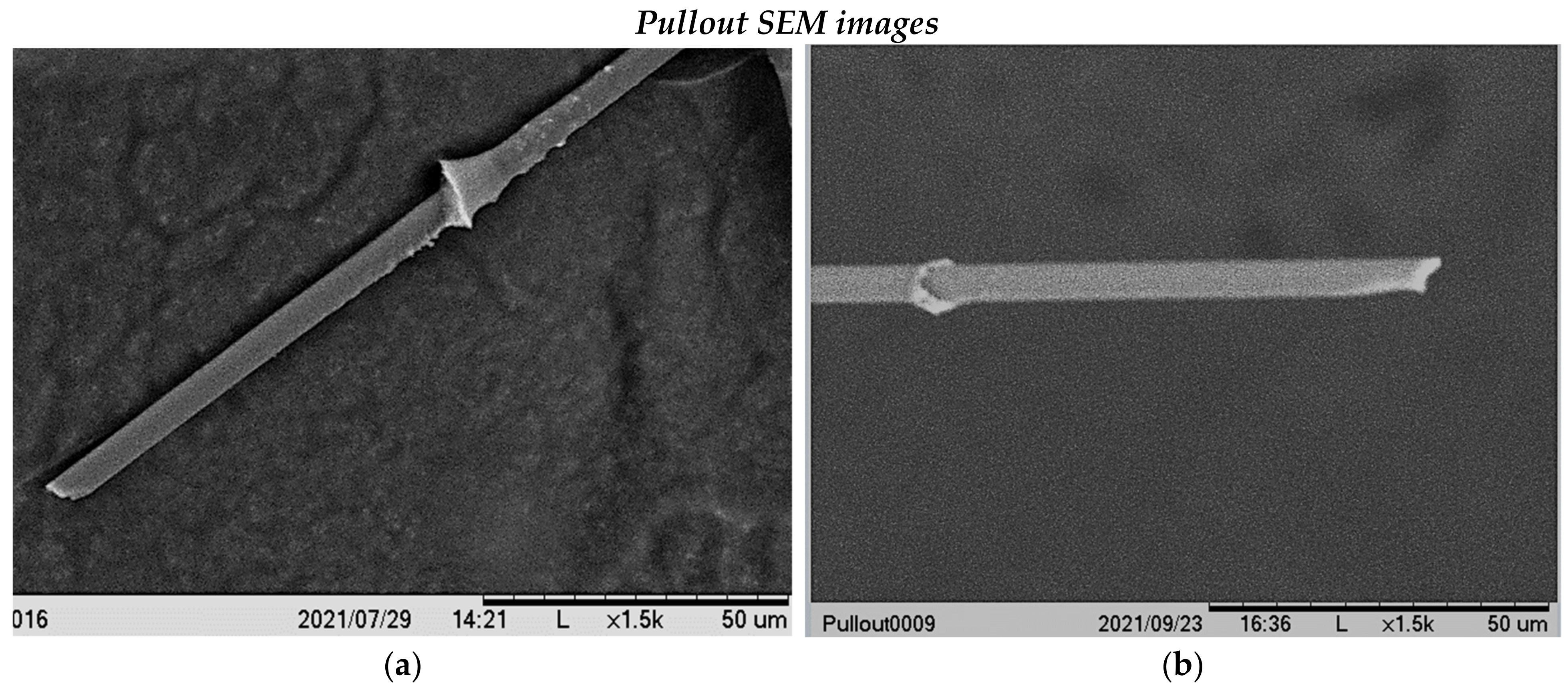
Post-test pullout SEM images Figure 7a,b show clean surfaces for both virgin and recycled fibers in general. Near the top of the vCF shown in Figure 7a, there is some evidence of residual resin on the fiber surface near the point where resin fracture initiated. In this specific case the resin meniscus is thin and inhomogeneities such as voids might cause fracture in the resin rather than at the interface. It should be noted that most of the fiber surface in Figure 7a is clean, as we see for the fiber surface in Figure 7b. These results are consistent with what is expected in the case where mechanical adhesion between the fiber and resin is moderate.
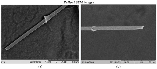
Figure 7.
Post-test pullout SEM images (a) vCF (b) rCF surfaces.
4.3. Fiber Length Measurement and Cumulative Distribution
The vCF and rCFs provided by Vartega are both supplied with a nominal fiber length of 3 mm. Fiber lengths of the supplied vCF, rCF, and cCF fibers are experimentally determined, as well as the fiber length of fibers extracted from the produced cCF TuFF sheet. To determine the fiber length, fibers are dispersed in a solution and placed on the surface of a high-resolution scanner. The material is scanned, and a Matlab image analysis program calculates the fiber length of each detected fiber from the scanned image.
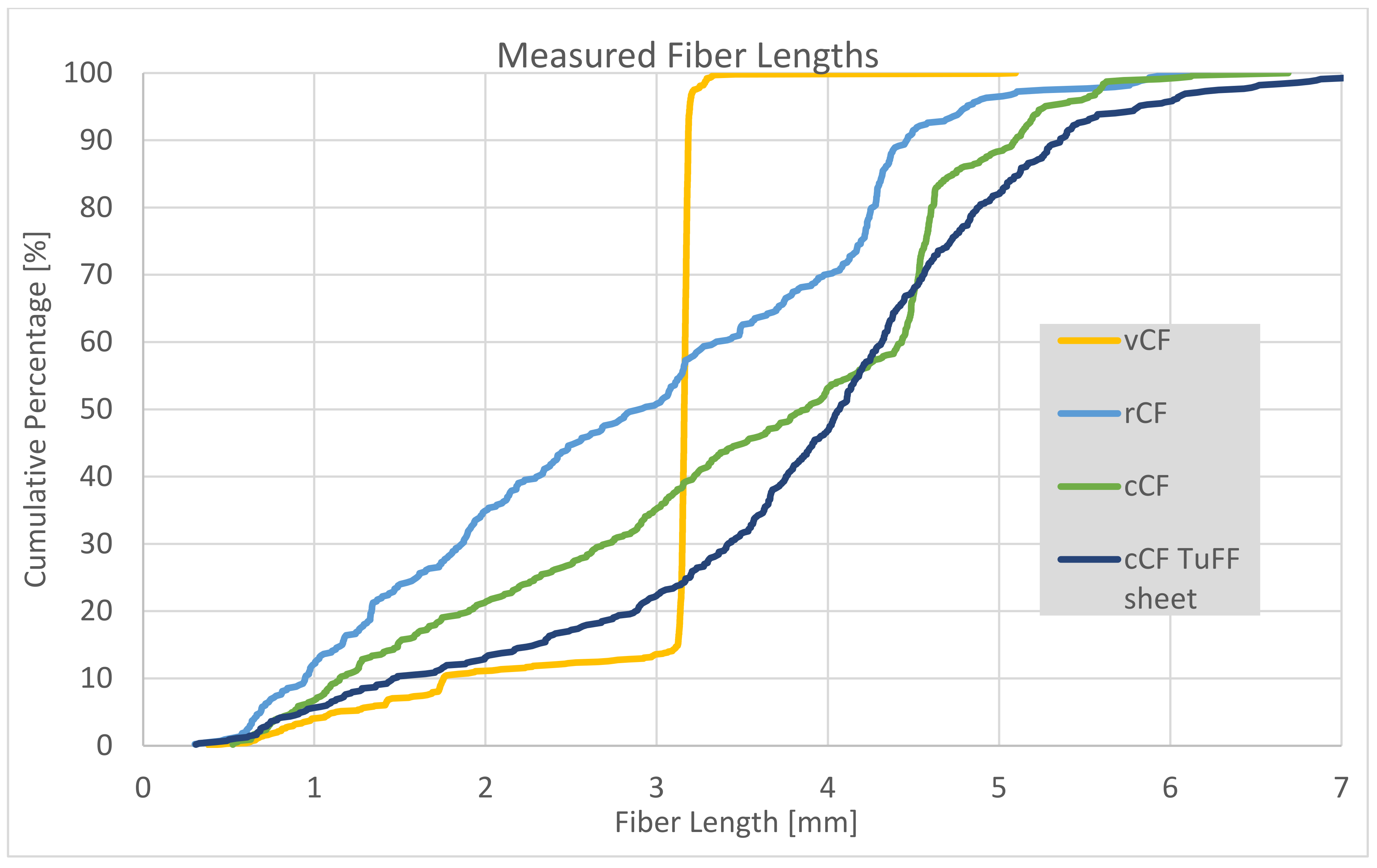
The resulting fiber length distribution is shown in Figure 8. The vCF fiber has 85% of the sampled fiber with a 3 mm cut length with no significantly longer fiber content. In contrast, the distribution of the rCF fiber lengths is broad with a uniform distribution between 0.5 mm and 6 mm. The cumulative distribution shows an increase in number density at around 4.2 mm. The Vartega process is proprietary and no additional information has been provided about their cutting process. The distribution is similar after the cleaning step and after TuFF processing with the highest fiber content between 3 mm and 5 mm. The number density of smaller fiber content below 4 mm in the cCFs is reduced, suggesting some loss during the cleaning step. Similarly, smaller fibers are filtered in the TuFF process during the water–fiber dispersion process. The effect of fiber length and aspect ratio distribution in TuFF composites is an ongoing investigation, but shorter fiber content should be avoided when full strength retention is required.

Figure 8.
Fiber length distributions of vCF, rCF, cCF, and cCF in TuFF sheet.
5. Composite Coupon Fabrication and Quality Assessment
TuFF fiber sheets are produced from the vCF and cCF fiber sources with a nominal areal weight Aw,fiber of 8 gsm. A total of 24 layers (200 mm by 150 mm) of the vCF and cCF material are laminated with 2 Axiom 72 gsm epoxy resin films. The density of the carbon fibers is 1.81 g/cm3 and the resin is 1.22 g/cm3. The fiber/resin areal weight ratio is selected to obtain a ~47% fiber volume fraction panel per Equation (1).
In the initial step, the mold and blank are heated to 50 °C and a vacuum is applied to begin the impregnation process. After 30 min, the temperature is ramped up to 122 °C at a rate of 2 degrees per minute. Once this temperature is achieved, 100 psi pressure is applied, and the material is held at this temperature and pressure for 60 min to complete the curing process. The mold is then cooled down to room temperature at 2 °C per minute. Fiber weight was measured prior to the layup and the final panel weight was obtained after the autoclave run. This is used to calculate an average FVF of 48% in both panels. Ultrasonic C-scan, photo microscopy, and fiber orientation measurement are then done to assess panel and alignment quality.
5.1. Ultrasonic Evaluation
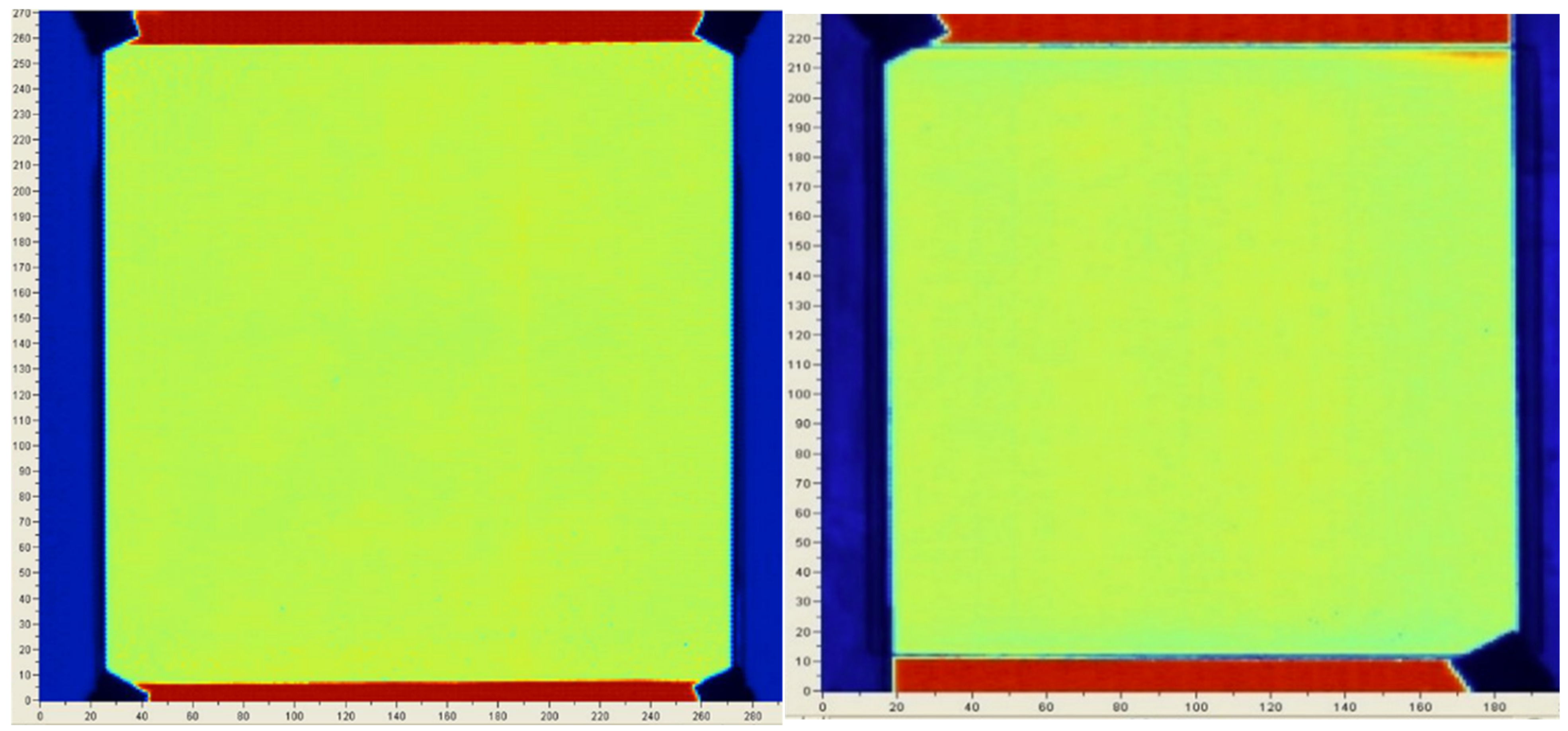
Ultrasonic C-scans are used to evaluate uniformity of the produced panels and are shown in Figure 9. Overall, both panels have similar attenuation of 4.5 dB ± 0.1 dB (vCF) and 4.1 dB ± 0.2 dB (cCF). Panels with significant fiber agglomerates in the TuFF sheets include small areas of high attenuation, which are not observed in these C-scans. C-scans provide a qualitative assessment of uniformity but cannot provide quantitative assessment of panel quality without calibration. Both TuFF panels are of uniform quality and the microstructural observation shown in the next section confirm that these panels have low porosity as well.
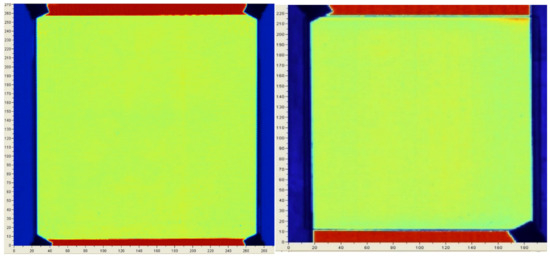
Figure 9.
Ultrasonic evaluation of vCF (left) and cCF (right) panels show consistent panel quality.
5.2. Photo Microscopy
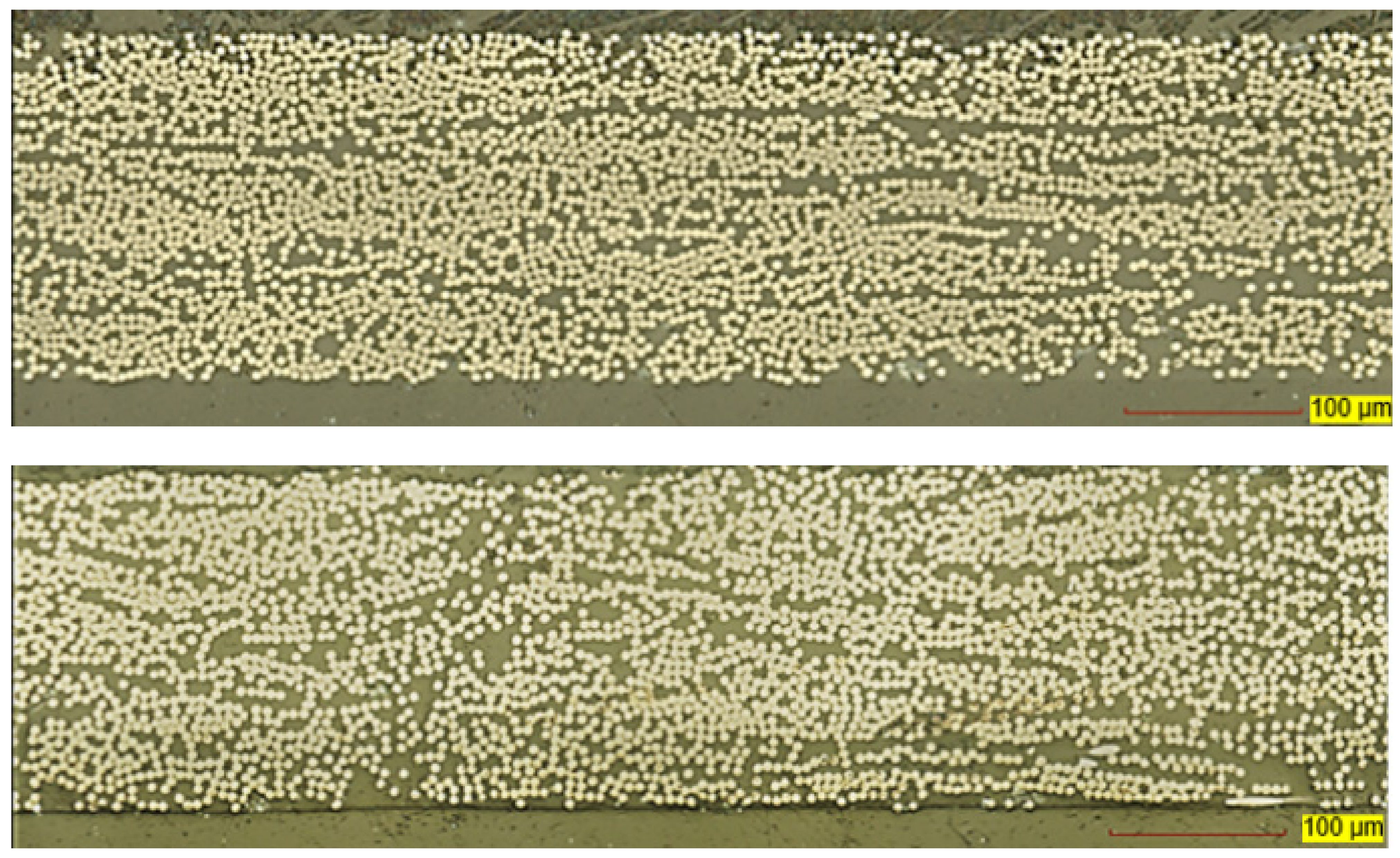
Optical microscopy images are captured using a 20× lens and the VK-X200 3D Color Laser Scanning Microscope, providing a resolution of 0.2 μm per pixel. Typical vCF and cCF cross-sectional images are shown in Figure 10. The microscopy images show low porosity (less than 2%) with some resin rich areas from a small number of misaligned fibers typically observed in TuFF coupons. Image analysis confirms FVF of around 50% as designed with the ratio of resin and fiber areal weight used in the autoclave process.
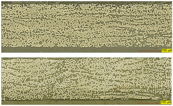
Figure 10.
Cross-section of vCF (top) and cCF (bottom) show no significant porosity.
To determine fiber alignment, microscopic images of a 15° cut are also generated. To precisely determine the fiber orientation, custom software was developed for image processing.
In Figure 11a, subsections of the prepreg microscopic images are displayed, illustrating the detected fiber perimeters obtained through the software analysis. The software calculates the ratio of minor and major axis of the ellipse and then computes the fiber orientation for each individual fiber. This microscopic approach evaluates many fibers (around 400 for both samples), providing a good assessment of the local alignment quality of the coupons. Figure 11b shows the resulting fiber orientation distribution with >95% of all fibers within 10° for both samples. The cumulative distribution looks very similar for both coupons with no major alignment issues identified, as shown in Figure 11b.
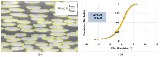
Figure 11.
(a) Example micrograph of a 15°-cut for fiber orientation (left), and (b) resulting fiber orientation distribution (right).
6. Results
This section summarizes the results of the mechanical property testing of the vCF and cCF TuFF coupons and compares them to the continuous fiber composites. The T800H continuous fiber prepreg properties are obtained from the Toray datasheet [31] and normalized to 48% FVF.
6.1. Mechanical Tests
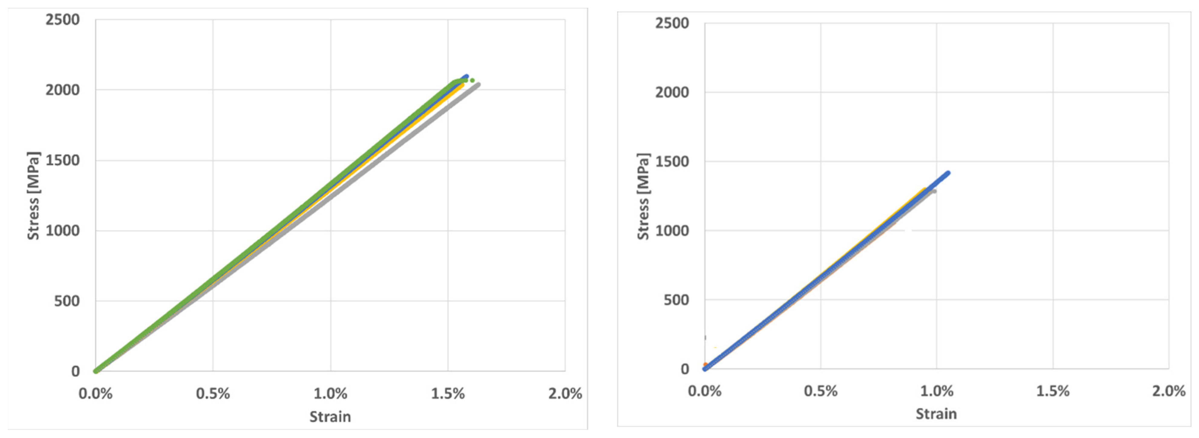
Five samples of each vCF and cCF TuFF panel are tested, and the stress–strain curves are shown in Figure 12. The stress–strain curves of the two composite panels are very similar until failure. However, the cCF panel had a significantly lower failure strain. This indicates comparable modulus for the two composite material with the cCF material exhibiting a lower strength. Failure strain of the vCF samples ranges from 1.47% to 1.63% and are slightly lower than the Toray datasheet failure strain at 1.67%. In contrast, the failure strain of the cCF samples is between 0.62% and 1.09%. This significantly lower failure strain results in the reduced average strength of the cCF composite.
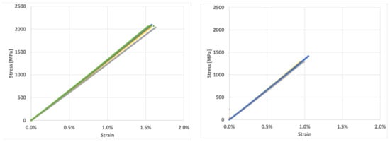
Figure 12.
Stress–strain curves for both vCF (left) and cCF coupons (right).
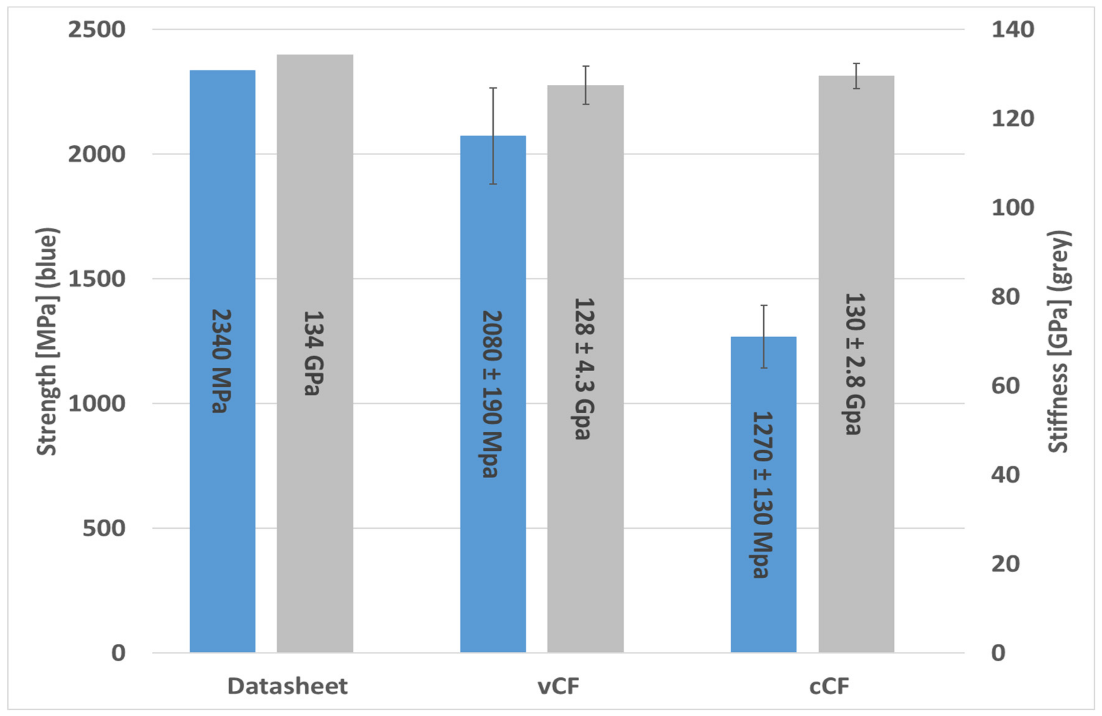
Using the tensile properties from the Toray datasheet for T800H unidirectional prepreg normalized at 48% FVF, the tensile strength and modulus is determined to be 2340 MPa and 132 GPa, respectively. The TuFF material produced using the vCF and cCF has a nearly identical tensile modulus of 128 ± 4.3 GPa and 130 ± 2.8 GPa, respectively, with both within one standard deviation of the Toray datasheet values. In addition, the stiffnesses are very repeatable, with an experimental coefficient of variation within 2–3%. In contrast, both TuFF samples had strength reductions compared to the Toray continuous fiber datasheet values. The vCF TuFF tensile strength is 2074 ± 190 MPa and the cCF TuFF tensile strength is 1270 ± 130 MPa. The vCF TuFF material has approximately 90% strength retention compared to the continuous sample while the cCF TuFF material retention drops to 55%. The cCF strength reduces by approximately 40% compared to the vCF coupon strength. The coefficient of variation for strength for both samples is higher, around 9–10%, which is not uncommon for composite tensile test results. Figure 13 summarizes the mechanical results in a graphical display.

Figure 13.
Tension tests show ~100% retention of stiffness for both vCF/cCF composites with a 10%/45% reduction in vCF/cCF strength, respectively.
Figure 14 compares our cCF TuFF properties with data from a recent review paper [9,10] of short, recycled carbon fiber composites. The cCF TuFF composite exceeds any reported short, recycled carbon fiber tensile properties by a factor of three, showing the significant property improvement possible with a highly aligned fiber material incorporating recycled fibers with full strength retention.
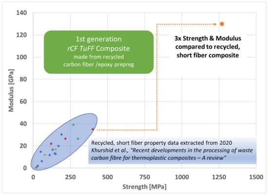
Figure 14.
Comparison of cCF TuFF properties with other composites using short, recycled carbon fibers [32].
6.2. Evaluation of Post-Mechanical Test Samples
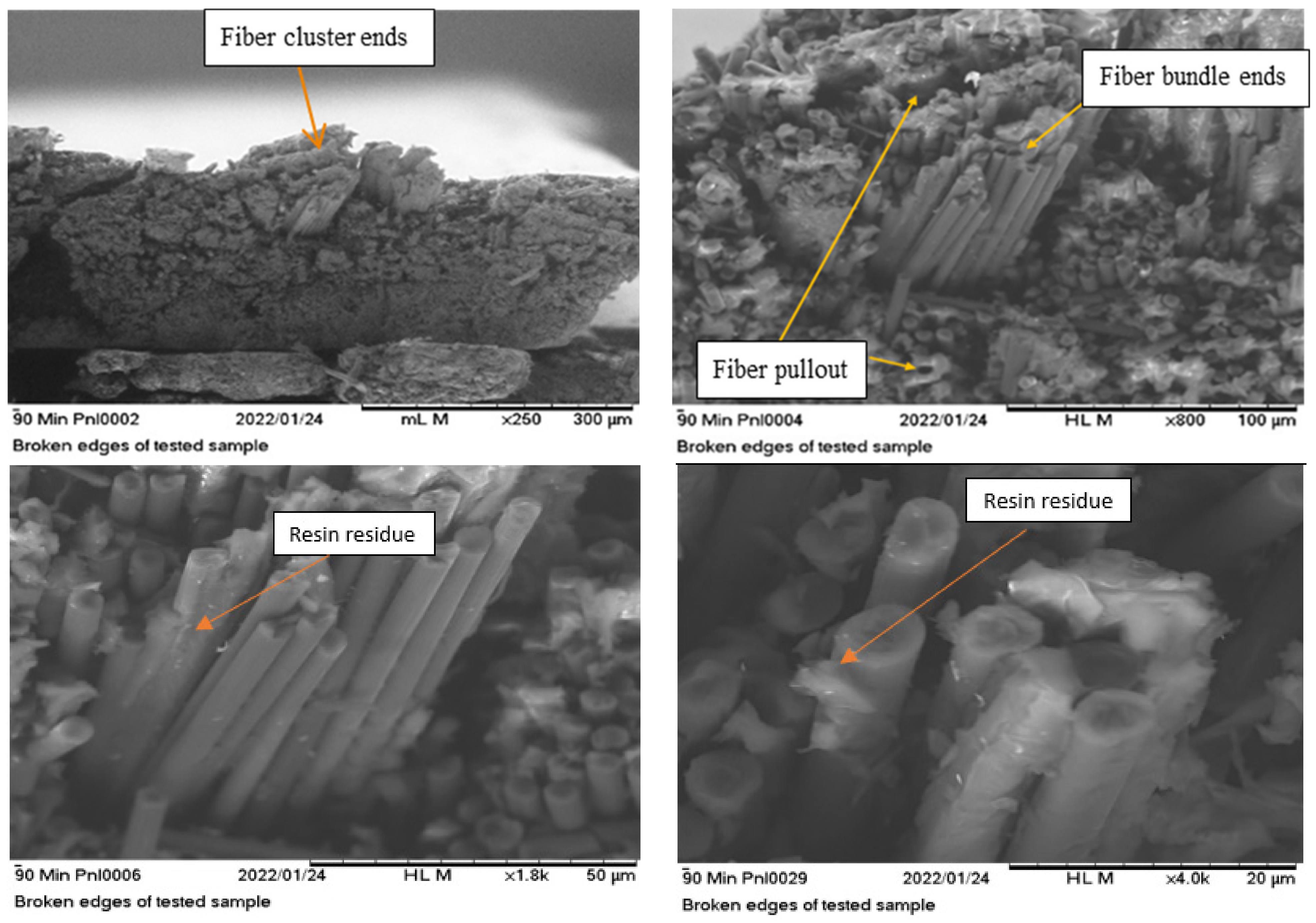
SEM pictures of the failed specimen surfaces are taken to evaluate potential failure modes in the cCF samples (Figure 15) in order to understand the reason for the observed drop in strength for the cleaned, recycled fiber. Close examination of the micrographs shows clusters of fibers where the ends of the filaments terminate at the same point, leading to a potential stress concentration that may induce premature failure in the composite. Evaluation of the fiber surfaces at high magnification shows evidence of pieces of resin on the fiber surface, indicating good fiber/resin adhesion consistent with the IFSS measurements. These results suggest that the primary failure mode is due to fiber bundles in the cCF sample creating stress concentrations and trigger the failure in the cleaned, recycled fiber sample. The mechanism leading to the observed clustering of fiber ends in the composite is unclear at this time. The pyrolysis cleaning process may leave a thin layer of residual degradation by-product in some areas of the fibers. This can promote the formation of a small number of fiber bundles either through friction or in some cases chemical bonding. This clusters are low in probability but could result in stress concentration and trigger premature damage initiation during mechanical testing of the large coupon sample.
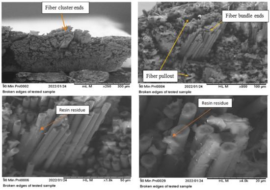
Figure 15.
SEM images of cCF failure surface show fiber cluster ends and fiber pull-out (top) with resin residue observed at higher magnification at the fiber ends (bottom).
7. Summary
This paper investigates the use of recycled carbon fibers in the TuFF process. Short fibers are recovered from prepreg in a multi-step process including solvolysis conducted by Vartega and an additional pyrolysis step under an inert environment to eliminate residue left on the solvolyzed fiber. This allows for good dispersion of the resulting fiber material in TuFF process. Fiber-resin adhesion, fiber length distribution, and fiber strength are measured for the vCF, rCF, and cCF materials. Adhesion and fiber strength is maintained throughout the recycling process with no significant degradation observed. Fiber length distribution of the recycled material from Vartega is broad and is significantly different from the length distribution of the vCF. The cause of this large length distribution is not known due to the proprietary solvolysis and cutting steps used by Vartega.
The vCFs and cCFs are aligned in the TuFF process to produce unidirectionally aligned plies. These are then laid up to a predetermined thickness, resin film is placed on the surface, and they are converted into flat coupons in the autoclave, resulting in~50% FVF composite coupons. The microstructure and overall panel quality was assessed and showed good alignment and low porosity in the samples. The tensile properties of both vCF and cCF coupons are measured and compared to Toray T800 composite datasheet properties. Full modulus translation is demonstrated, but the strength is reduced to 90% for the vCF composite and 55% for the cCF composite. Properties were compared to literature data of recycled, short fiber composites and showed significant improvement of composite tensile strength and modulus with our rTuFF approach.
Author Contributions
Conceptualization, D.H., J.M.D. and S.Y.; methodology, T.O., D.H. and J.M.D.; validation, D.H., J.M.D., T.O. and R.C.; formal analysis, T.O.; investigation, T.O.; resources, D.H. and J.M.D.; data curation, T.O., R.E., C.B. and M.D.; writing—T.O. and D.H.; writing—review and editing, D.H., J.M.D., R.C. and T.O.; supervision, D.H. and J.M.D.; project administration, D.H. and J.M.D.; funding acquisition, D.H. and J.M.D. All authors have read and agreed to the published version of the manuscript.
Funding
This research was funded by the U.S. Department of Energy, Office of Science under Award Number DE-SC0019970.
Data Availability Statement
The raw data supporting the conclusions of this article will be made available by the authors on request.
Acknowledgments
Special thanks to Vartega Inc., Denver, CO, USA for providing us with their recycled fiber material.
Conflicts of Interest
Authors Roger Crane, Chris Blackwell, Mark Davis were employed by the company Composites Automation LLC. The remaining authors declare that the research was conducted in the absence of any commercial or financial relationships that could be construed as a potential conflict of interest.
References
- Naqvi, S.; Prabhakara, H.; Bramer, E.; Dierkes, W.; Akkerman, R.; Brem, G. A critical review on recycling of end-of-life carbon fibre/glass fibre reinforced composites waste using pyrolysis towards a circular economy. Resour. Conserv. Recycl. 2018, 136, 118–129. [Google Scholar] [CrossRef]
- Statista, Carbonfaserverstärkte Kunststoffe: Nachfrage Weltweit bis 2023, Statista. Available online: https://de.statista.com/statistik/daten/studie/660055/umfrage/nachfrage-von-carbonfaserverstaerkten-kunststoffen-weltweit/ (accessed on 31 August 2021).
- JEC Group. JEC Observer: Current Trends in the Global Composites Industry 2020–2025. Paris, 2021. Available online: https://www.jeccomposites.com/press/the-jec-observer-current-trends-in-the-global-composites-industry-2020-2025/ (accessed on 31 August 2021).
- Lengsfeld, H.; Mainka, H.; Altstädt, V. Carbon Fibers: Production, Applications, Processing; Hanser: Munich, Germany; Cincinnati, OH, USA, 2021; pp. 179–192. [Google Scholar] [CrossRef]
- Krauklis, A.; Karl, C.; Gagani, A.; Jørgensen, J. Composite Material Recycling Technology—State-of-the-Art and Sustainable Development for the 2020s. J. Compos. Sci. 2021, 5, 28. [Google Scholar] [CrossRef]
- Yang, J.; Liu, J.; Liu, W.; Wang, J.; Tang, T. Recycling of carbon fibre reinforced epoxy resin composites under various oxygen concentrations in nitrogen-oxygen atmosphere. J. Anal. Appl. Pyrolysis 2015, 112, 253–261. [Google Scholar] [CrossRef]
- Mazzocchetti, L.; Benelli, T.; D’Angelo, E.; Leonardi, C.; Zattini, G.; Giorgini, L. Validation of carbon fibers recycling by pyro-gasification: The influence of oxidation conditions to obtain clean fibers and promote fiber/matrix adhesion in epoxy composites. Compos. Part A Appl. Sci. Manuf. 2018, 112, 504–514. [Google Scholar] [CrossRef]
- He, D.; Soo, V.K.; Stojcevski, F.; Lipiński, W.; Henderson, L.C.; Compston, P.; Doolan, M. The effect of sizing and surface oxidation on the surface properties and tensile behavior of recycled carbon fibre: An end-of-life perspective. Compos. Part A Appl. Sci. Manuf. 2020, 138, 106072. [Google Scholar] [CrossRef]
- Morin, C.; Serani, A.; Cansell, F.; Aymonier, C. Near- and supercritical solvolysis of carbon fibre reinforced polymers (CFRPs) for recycling carbon fibers as a valuable resource: State of the art. J. Supercrit. Fluids 2012, 66, 232–240. [Google Scholar] [CrossRef]
- Dang, W.; Kubouchi, M.; Sembokuya, H.; Tsuda, K. Chemical recycling of glass fibre reinforced epoxy resin cured with amine using nitric acid. Polymer 2005, 46, 1905–1912. [Google Scholar] [CrossRef]
- Liu, Y.; Meng, L.; Huang, Y.; Du, J. Recycling of carbon/epoxy composites. J. Appl. Polym. Sci. 2004, 94, 1912–1916. [Google Scholar] [CrossRef]
- Pimenta, S.; Pinho, S. Recycling carbon fibre reinforced polymers for structural applications: Technology review and market outlook. Waste Manag. 2011, 31, 378–392. [Google Scholar] [CrossRef] [PubMed]
- Longana, M.; Ong, N.; Yu, H.; Potter, K. Multiple closed loop recycling of carbon fibre composites with the HiPerDiF (High Performance Discontinuous Fibre) method. Compos. Struct. 2016, 153, 271–277. [Google Scholar] [CrossRef]
- Yarlagadda, S.; Deitzel, J.; Heider, D.; Tierney, J.; Gillespie, J., Jr. Tailorable Universal Feedstock for Forming (TuFF): Overview and Performance. In Proceedings of the SAMPE Conference Proceedings, Charlotte, NC, USA, 20–23 May 2019. [Google Scholar] [CrossRef]
- Heider, D.; Yarlagadda, S.; Blackwell, C.; Crane, R.; Davis, M.; Emmerich, R.; Deitzel, J.; Ozdemir, T. Carbon Fiber Composites Recycling Technology Enabled by The TuFF Technology; SAMPE: Charlotte, NC, USA, 2022. [Google Scholar] [CrossRef]
- Blackwell, C.; Crane, R.; Tierney, J.; Deitzel, J.; Ozdemir, T.; Heider, D. Short Fiber TuFF Technology for Automotive Part Production via Wet Compression; SAMPE: Charlotte, NC, USA, 2022. [Google Scholar] [CrossRef]
- Liu, W.; Huang, H.; Cheng, H.; Liu, Z. CFRP Reclamation and Remanufacturing Based on a Closed-loop Recycling Process for Carbon Fibers Using Supercritical N-butanol. Fibers Polym. 2020, 21, 604–618. [Google Scholar] [CrossRef]
- Tierney, J.; Vanarelli, A.; Heider, D.; Yarlagadda, S.; Gillespie, J.W., Jr. Aligned Discontinuous Fiber Preforms, Composites and Systems and Process of Manufacture. U.S. Patent No. 11047078, 29 June 2021. [Google Scholar]
- Tierney, J.; Vanarelli, A.; Heider, D.; Yarlagadda, S.; Gillespie, J.W., Jr. Aligned Discontinuous Fiber Preforms, Composites and Systems and Processes of. Manufacture. Patent No. US 10,669,659 B2, 2 June 2020. [Google Scholar]
- Butenegro, J.A.; Bahrami, M.; Abenojar, J.; Martínez, M.Á. Recent progress in carbon fiber reinforced polymers recycling: A review of recycling methods and reuse of carbon fibers. Materials 2021, 14, 6401. [Google Scholar] [CrossRef] [PubMed]
- Tranchard, P.; Duquesne, S.; Samyn, F.; Estèbe, B.; Bourbigot, S. Kinetic analysis of the thermal decomposition of a carbon fibre-reinforced epoxy resin laminate. J. Anal. Appl. Pyrolysis 2017, 126, 14–21. [Google Scholar] [CrossRef]
- Lee, S.H.; Choi, H.O.; Kim, J.S.; Lee, C.-K.; Kim, Y.K.; Ju, C.S. Circulating flow reactor for recycling of carbon fibre from carbon fibre reinforced epoxy composite. Korean J. Chem. Eng. 2011, 28, 449–454. [Google Scholar] [CrossRef]
- Shibata, K. FRP Recycling Technology by Dissolving Resins under Ordinary Pressure, JEC Composite. 2011. Available online: https://digital-magazine.jeccomposites.com/reader/preview/e6cf8bae-2dfd-4555-9812-78560448e5a0 (accessed on 30 January 2024).
- Oliveux, G.; Dandy, L.; Leeke, G.A. Current status of recycling of fibre reinforced polymers: Review of technologies, reuse and resulting properties. Prog. Mater. Sci. 2015, 72, 61–99. [Google Scholar] [CrossRef]
- Oliveux, G.; Bailleul, J.L.; Gillet, A.; Mantaux, O.; Leeke, G.A. Recovery, and reuse of discontinuous carbon fibres by solvolysis: Realignment and properties of remanufactured materials. Compos. Sci. Technol. 2017, 139, 99–108. [Google Scholar] [CrossRef]
- Bel Haj Frej, H.; Léger, R.; Perrin, D.; Jenny, P.; Gérard, P.; Devaux, J.-F. Recovery and reuse of carbon fibre and acrylic resin from thermoplastic composites used in marine application. Resour. Conserv. Recycl. 2021, 173, 105705. [Google Scholar] [CrossRef]
- Langston, T.A.; Granata, R.D. Influence of nitric acid treatment time on the mechanical and surface properties of high-strength carbon fibers. J. Compos. Mater. 2012, 1, 18. [Google Scholar] [CrossRef]
- Huan, X.; Shi, K.; Yan, J.; Lin, S.; Li, Y.; Jia, X.; Yang, X. High performance epoxy composites prepared using recycled short carbon fiber with enhanced dispersibility and interfacial bonding through polydopamine surface-modification. Compos. Part B 2020, 193, 107987. [Google Scholar] [CrossRef]
- Kubota, M.; Chowdhury, S.; Deitzel, J.M.; Gillespie, J.W.; Palmese, G.R. Tailoring the S-2 Glass/Epoxy Interface Properties through Chemical Vapor Deposition of Silane Adhesion Promotors. In Proceedings of the American Society of Composites 35th Technical Conference, Online, 14–17 September 2020. [Google Scholar] [CrossRef]
- Chen, B.; Parambil, N.K.; Deitzel, J.M.; Gillespie, J.W.; Vo, L.T.; Sarosi, P. Interfacial shear strength (IFSS) and absorbed energy versus temperature in carbon fiber-thermoplastic composites via single fiber pullout testing. In Proceedings of the American Society of Composites 35th Technical Conference, Online, 14–17 September 2020. [Google Scholar] [CrossRef]
- Toray Composite Materials America, Inc. T800H Carbon Fiber-Toray Composite Materials America, Inc. Available online: https://www.toraycma.com/products/carbon-fiber/ (accessed on 1 November 2021).
- Khurshid, M.F.; Hengstermann, M.; Hasan, M.M.B.; Abd Kader, A.; Cherif, C. Recent developments in the processing of waste carbon fibre for thermoplastic composites—A review. J. Compos. Mater. 2019, 54, 14. [Google Scholar] [CrossRef]


Disclaimer/Publisher’s Note: The statements, opinions and data contained in all publications are solely those of the individual author(s) and contributor(s) and not of MDPI and/or the editor(s). MDPI and/or the editor(s) disclaim responsibility for any injury to people or property resulting from any ideas, methods, instructions or products referred to in the content. |
© 2024 by the authors. Licensee MDPI, Basel, Switzerland. This article is an open access article distributed under the terms and conditions of the Creative Commons Attribution (CC BY) license (https://creativecommons.org/licenses/by/4.0/).