1. Introduction
Plastic is in rapidly growing demand due to its inexpensive production costs, as well as its many useful properties, such as lightweight, chemical resistance, durability, and longevity. This results in a high generation rate of plastic waste. Globally to date, 1.6 million tonnes of plastic waste are thought to have been produced every day during the COVID-19 outbreak [
1]. Similar to worldwide, Thailand is also facing plastic waste problems. About 25.37 million tonnes of municipal solid waste were produced in Thailand during the pandemic, of which 2 million tonnes was plastic waste. In addition, plastic waste is also found as a part of waste of electrical and electronic equipment (commonly known as e-waste). It was reported that electrical and electronic wastes in Thailand amounted to 4.28 million tonnes, of which 20% were plastics [
2]. This dramatic rise in plastic waste might cause a wide range of environmental problems, including the ingestion, suffocation, and entanglement of hundreds of marine species due to mismanagement [
3]. Therefore, there is a strong need to increase plastic recycling accordingly. The mixed plastic waste should be effectively separated to achieve a good recycled plastic quality since some plastics are not compatible with others while re-melting and can radically obstruct the development of plastic recycling.
There are many types of plastics contained in the waste streams, such as polypropylene (PP), polyethylene (PE), acrylonitrile-butadiene-styrene (ABS), polyvinyl chloride (PVC), polystyrene (PS), and polyethylene terephthalate (PET) [
4]. Among these types of plastics, ABS is the most concern because it contains numerous hazardous additives such as brominated flame retardants (BFRs) to prevent damaging effects from the burning of electronic and electrical equipment [
5]. The presence of ABS in very small quantities can significantly decrease the recycling ratio and deteriorate the recycled products by forming compounds with the main plastics. To reduce the severely negative impact on recycling performance, human health, and the surrounding environment, ABS must be separated from plastic mixtures.
Numerous separation techniques have been developed for plastic recycling, such as manual sorting, gravity separation [
6,
7,
8], and selective flotation [
9,
10,
11]. Manual sorting is a labor-intensive process since it relies on the accuracy of human labor to identify the different plastics based on appearance; gravity separation is a separation technique based on their specific gravity differences. However, these techniques are significantly limited to separate mixed plastic wastes with analogous physicochemical characteristics such as PS and ABS [
12]. These two plastic types can be found together in electronic and electrical appliances, automotive products, and household equipment. Thus, flotation separation of PS and ABS is of significance for improving the recycling of plastic waste. For that reason, selective flotation attracts a lot of attention due to its cost-effective and notable efficiency for the separation of mixed plastics with analogous physicochemical characteristics [
13].
Selective flotation is a physicochemical process based on the selective adhesion of specific solid particles according to their surface property. The mixed solid particles and liquid medium (e.g., water) are conditioned with specific chemical reagents for differing the surface property of each solid particle and promoting the selective formation of aggregates between solid particles and air bubbles. The system is then gradually filled with air drawn from the atmosphere to produce air bubbles that can attach to more hydrophobic particles. Hydrophobic particles can float to the water’s surface in the flotation cell and be recovered as a floated product because the density of the solid-bubble aggregates created by the attachment of bubbles to the solid surface is lower than that of water. On the contrary, hydrophilic particles remain in the water and become a non-floated product. Therefore, it is possible to separate the mixed solid particles [
14]. As mentioned, one of the significant factors for improving the separation efficiency in the selective flotation process is not only the addition of chemicals for changing the particle surface property but also the generation of air bubbles. Generally, an air diffuser is applied in the flotation process due to its availability and controllable bubble size [
12]. However, there are some drawbacks of air diffusers that should be taken into account, such as clogging, high-pressure loss, and energy consumption.
Induced Air Flotation (IAF) with a mixing device is a flotation process with an alternative bubble generation system. In this process, a negative pressure is produced by mixing at a high rotational speed. This introduces air bubbles into the system by inducing air from the atmosphere through an induced air tube [
15]. In addition, a rotational motion produced by the mixing device forces the liquid and particles to move through the reactor, improving the suspension of particles and the dispersion of chemical reagents in the system. Therefore, IAF takes advantage of producing substantial air bubbles in the system as well as promoting the selective wetting of particles and the contact between particles and bubbles. However, this system is complicated by many factors associated with bubble generation phenomena. Moreover, the hydrodynamic bubble parameters (e.g., bubble size, bubble rising velocity, and gas flow rate) and mixing conditions should be well considered for a better understanding of the process design and operation as well as to improve plastic separation efficiency.
The objective of this work is thus to study the effects of design and operational factors on the bubble’s hydrodynamic and mixing parameters in induced air flotation (IAF) with a mixing device. A design of experiment (DOE) using Plackett-Burman (PB) design and a central composite design approach-based response surface methodology (RSM-CCD) are employed for screening significantly related factors and optimizing IAF performance on the PS and ABS separation, respectively. Additionally, the hydrodynamic bubble parameters relative to the terms of the ratio of interfacial area to velocity gradient (a/G) are applied to evaluate the separation efficiency.
2. Materials and Methods
2.1. Experimental Setup
All experiments plastic separation experiments were carried out in the modified IAF unit which consists of two parts; (1) a cylindrical-shaped reactor with 23 cm in diameter and 33 cm in height and (2) a bubble generation system that includes a mixing device using a pitched blade turbine impeller with a diameter of 6 cm (Platinum engineering and service company limited, Thailand) and two transparent tubes, placed between an air–water interface and covered on a mixing device for inducing the air into the system. The bubble generation system is connected to the AC motor, which has a range of rotational speed of 0 to 3000 rpm (Platinum engineering and service company limited, Thailand). To study the hydrodynamic bubble parameters, a high-speed camera connected to a computer was employed to record the bubble characteristics produced by the modified IAF unit, then the hydrodynamic parameters (i.e., bubble size) were analyzed from taken images by the image analysis software.
Tannic acid (Loba chemie Co., Ltd., Mumbai, India), Calcium chloride (CaCl2), and Polyoxyethylene (5) Lauryl Ether (Thai Ethoxylate Co., Ltd., Rayong, Thailand) were applied as a wetting agent, a density modifying agent, and a surface tension modifying agent (surfactant), respectively. Tap water was used throughout the experiments to prepare the liquid medium. All experiments were carried out at room temperature (25 ± 1 °C).
The entire setup of the plastic separation using the modified IAF process and the details of the bubble generation system are shown in
Figure 1.
2.2. Plastic Sample Preparation
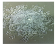
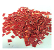
The two used plastic types, including polystyrene (PS from CD case) and acrylonitrile butadiene styrene (ABS from fan frame), were cut into the size range of 3–5 mm. To facilitate the manual sorting at the end of each experiment, these two plastic types had different colors (i.e., transparent PS and dark red ABS). An analytical balance with the density kit was employed to quantify the average sample density from 5 samples (Sartorius, BP210).
The characteristics of PS and ABS plastics, including their appearance, size, and density, are displayed in
Table 1.
2.3. Experimental Design and Statistical Analysis
For screening the significantly related factors of the IAF process generated by mixing devices and optimizing its performance on plastic separation, a design of experiment (DOE) using Plackett-Burman (PB) design and a central composite design approach-based response surface methodology (RSM-CCD) were applied.
2.3.1. Plackett-Burman (PB) Design
The PB design was first applied to screen the key factors affecting the bubble size from all interesting variables with a few experimental runs [
16]. The interesting variables in this work included six variables; an induced air tube diameter (x1), a rotational speed (x2), a spacing distance between tube and impeller (x3), a spacing distance between the tube and liquid surface (x4), the concentration of polyoxyethylene (5) lauryl ether (x5), and the concentration of tannic acid (x6). The experiments were carried out with 12 runs for screening the key factors affecting the bubble size. Each assigned variable was set at 2 levels (high and low), denoted as +1 and −1, respectively, as shown in
Table 2. The details of six variables with designate at low and high levels are shown in
Table 3. Student’s
t-test with a 95% confidence level was applied to examine the significance of each variable affecting the bubble size.
2.3.2. Response Surface Methodology-based Central Composite Design (RSM-CCD)
The RSM-CCD was then applied to investigate the effect of hydrodynamic parameters on the plastic separation using a modified IAF process and to optimize its operational conditions. The significant factors after screening using PB design were assessed at five coded levels (–α, –1, 0, +1, and +α) [
17], as shown. Note that α can be calculated by Equation (1).
where x is the number of significant factors.
Minitab 13 statistical package (MINITAB Inc., State College, PA, USA) was used for the statistical analysis of the results.
2.4. Analytical Parameters
In this work, the analytical parameters were categorized into two types; (1) the parameters related to the hydrodynamic bubble phenomena, including bubble size, bubble formation frequency, bubble rising velocity, interfacial area, and velocity gradient, and (2) the parameters related to the separation process such as plastic recovery percentage.
2.4.1. Bubble Size (Db)
First, the generated bubbles were photographed by a high-speed camera and their bubble sizes were then analyzed by the image analysis software. The averaged bubble size (D
b) was calculated and presented in terms of the Sauter mean diameter (d
32), which is the mean diameter with the same ratio of volume to the surface area as the entire ensemble. The calculation of d
32 can be expressed in Equation (2) [
18].
where d
v is the volume diameter, d
s is the surface diameter, V
b is the volume of bubbles, and A
b is the surface area of bubbles.
2.4.2. Bubble Formation Frequency (fb)
Bubble formation frequency (f
b) is defined as the number of bubbles formed per unit time. It can be calculated by Equation (3) [
19].
where Q
g is gas flowrate. Note that the Q
g in this work was measured by a soap film meter method [
20].
2.4.3. Bubble Rising Velocity (Ub)
Bubble rising velocity (U
b) refers to the distance bubbles move per unit time. It can be estimated from the distance covered by the bubble between two frames [
19], as expressed in the following equation.
where ∆D is the bubble spatial displacement between t = 0 and t = T
frame = 1/500 s.
2.4.4. Interfacial Area (a)
Interfacial area (a) is defined as the total contact area of the bubbles. It is a function of the f
b, U
b, and D
b, as shown in Equation (5) [
19].
where N
b, S
b, V
total, and H
L are the number of bubbles, the surface area of the bubbles, the volume of the liquid, and the height of the liquid, respectively.
2.4.5. Velocity Gradient (G)
Velocity gradient (G) refers to the difference in velocity between adjacent layers of the fluid. It can be calculated from the following equation [
21].
where μ is the dynamic viscosity and P is the required power.
Since the modified IAF process developed in this work is a combined flotation–stirring process, the P value should be determined from both mechanical and pneumatic mixing processes. For P imparted by a mechanical mixing process (P
mechanical), the calculation of P
mechanical is given by the following equation [
21].
where n, D, and ρ are rotational speed (rps), impeller diameter (m), and density of liquid, respectively. K
T is defined as an impeller constant for turbulent flow. Note that the K
T of the pitched blade turbine used in this work is equal to 1.00 [
22].
Furthermore, the P imparted by the pneumatic mixing process (P
pneumatic), can be calculated from Equation (8) [
21].
where C
1 and H are the constants equal to 3904 and the air pressure at the point of discharge expressed in meters of water, respectively. Q
g is the air flow rate at operational temperature and pressure (m
3/s).
2.4.6. Plastic Separation Efficiency
The mixed plastic separation efficiency can be calculated in two terms, including the plastic recovery efficiency (%Recovery) and the plastic purity efficiency (%Purity) from the following equations.
3. Results and Discussion
The results were divided into three main parts; (1) study of the developed bubble generation system through PB design, (2) optimization of the modified IAF for plastic separation through RSM-CCD, and (3) impact of hydrodynamic parameters (i.e., a/G) on the effectiveness of plastic separation
3.1. Study of the Developed Bubble Generation System through PB Design
As IAF with a mixing device is complicated due to numerous related factors with bubble generation phenomena. Therefore, the PB design was employed to screen key factors that affected the bubble size of the developed bubble generation system. Six assigned variables of this study, including an induced air tube diameter (x1), a rotational speed (x2), a spacing distance between tube and impeller (x3), a spacing distance between tube and liquid surface (x4), the concentration of polyoxyethylene (5) lauryl ether (x5), and the concentration of tannic acid (x6), were screened in 12 experimental runs. To assure the reproducibility of the results, each experiment was performed at least two times. The mean of the bubble sizes with standard derivation was taken as a response (
Table 4).
According to the bubble diameter results in
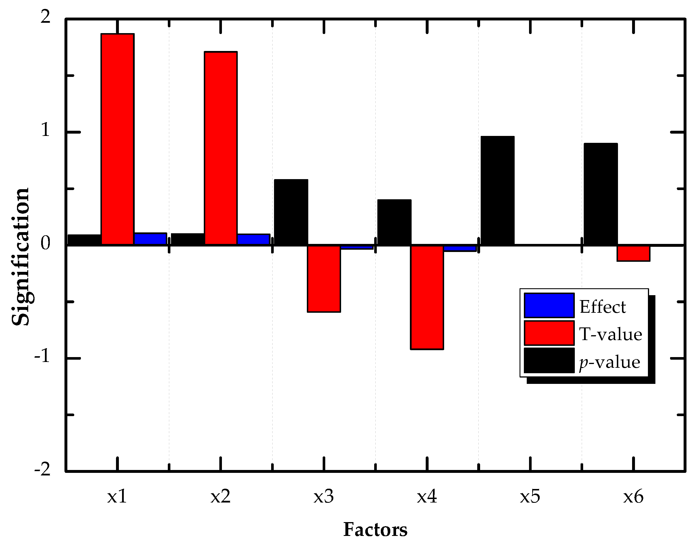
Table 4, the largest and the smallest bubble diameters that were obtained from PB’s desired conditions were 1.073 ± 0.005 and 0.714 ± 0.016 mm, respectively. This demonstrates that the modified IAF could produce a small bubble size in the range of mm. The significance level of the assigned variables was then taken into account using a regression analysis with a Student’s
t-test with a 95% confidence interval. The influence on the response factor was stronger when the variable had a small
p-value and a high absolute T-value [
23]. From the analysis of variance (ANOVA) in
Figure 2 based on the
p-value, the absolute value of the T-value, and its effective level, only two significant effect factors, including induced air tube diameter (x1) and a rotational speed (x2), were found to exhibit their significant roles in the generation of small bubble size by the modified IAF. In order to better understand the bubble’s hydrodynamic and mixing parameters from the modified IAF, these two factors were chosen to be analyzed in detail using CCD experiments.
3.2. Optimization of the Modified IAF through RSM-CCD
The induced air tube diameter (x1) and the rotational speed (x2), two significant factors that were previously screened by the PB design, were further examined for their effects on the bubble’s hydrodynamic and mixing parameters, which are directly related to the plastic separation efficiency. The operational conditions were then optimized using RSM-CCD. These two factors, x1 and x2, were chosen as independent factors to be assessed at five coded levels (−α, –1, 0, +1, and +α). In detail, the experimental values of x1 and x2 were in a range of 1.25–2.75 inches and 450–900 rpm. The mean bubble diameters with standard derivation were taken as a response. A total of 11 experimental runs were carried out, including 4 factorial, 4 axial, and 3 center runs. Note that the value of 1.5 was chosen for α to fulfill the ratability in the design instead of 1.68 due to the fixation of the induced air tube diameter on the commercial market. In addition, a space between the tube and liquid surface of 1 cm, a space between the tube and impeller of 1 cm, and a tannic acid concentration of 25 mg/L were applied through the RSM-CCD experiments.
The modified IAF was operated following the experimental conditions desired by RSM-CCD, and the obtained bubble diameters are shown in
Table 5. It can be seen that the actual bubble diameters obtained from the desired experiments were in the range of 0.8 to 1.3 mm. Additionally, the obtained model that described the relationship between the independent variables (x1 and x2) and the response variable (bubble diameter) is displayed in Equation (11).
To evaluate the precision and the competency of the model, the root-mean-square error (RMSE) was applied. This method is frequently used to measure the differences between the values predicted by the model and the observed values. According to
Table 5, this prediction model provided the highest RMSE of 0.162. It demonstrates that the application of the model for predicting the bubble diameter using the modified IAF provided an accuracy of more than 80%.
Aside from bubble diameter, other bubble’s hydrodynamic and mixing parameters, such as a, G, and a/G, were also examined by RSM-CCD to gain a deeper knowledge of the process design and operation for improving the plastic separation efficiency.
Interfacial area, a, is one of the bubble-based parameters that refer to the total contact area of bubbles. This parameter directly relates to Db, Ub, and fb. Likewise, the velocity gradient, G, represents the proper mixing condition and the turbulence in the process. Both parameters affect the contact probability between particle surface and bubbles, relating to the increase or decrease in the separation efficiency. The calculated a, G, and a/G for each RSM-CCD-desired condition are shown in
Table 6.
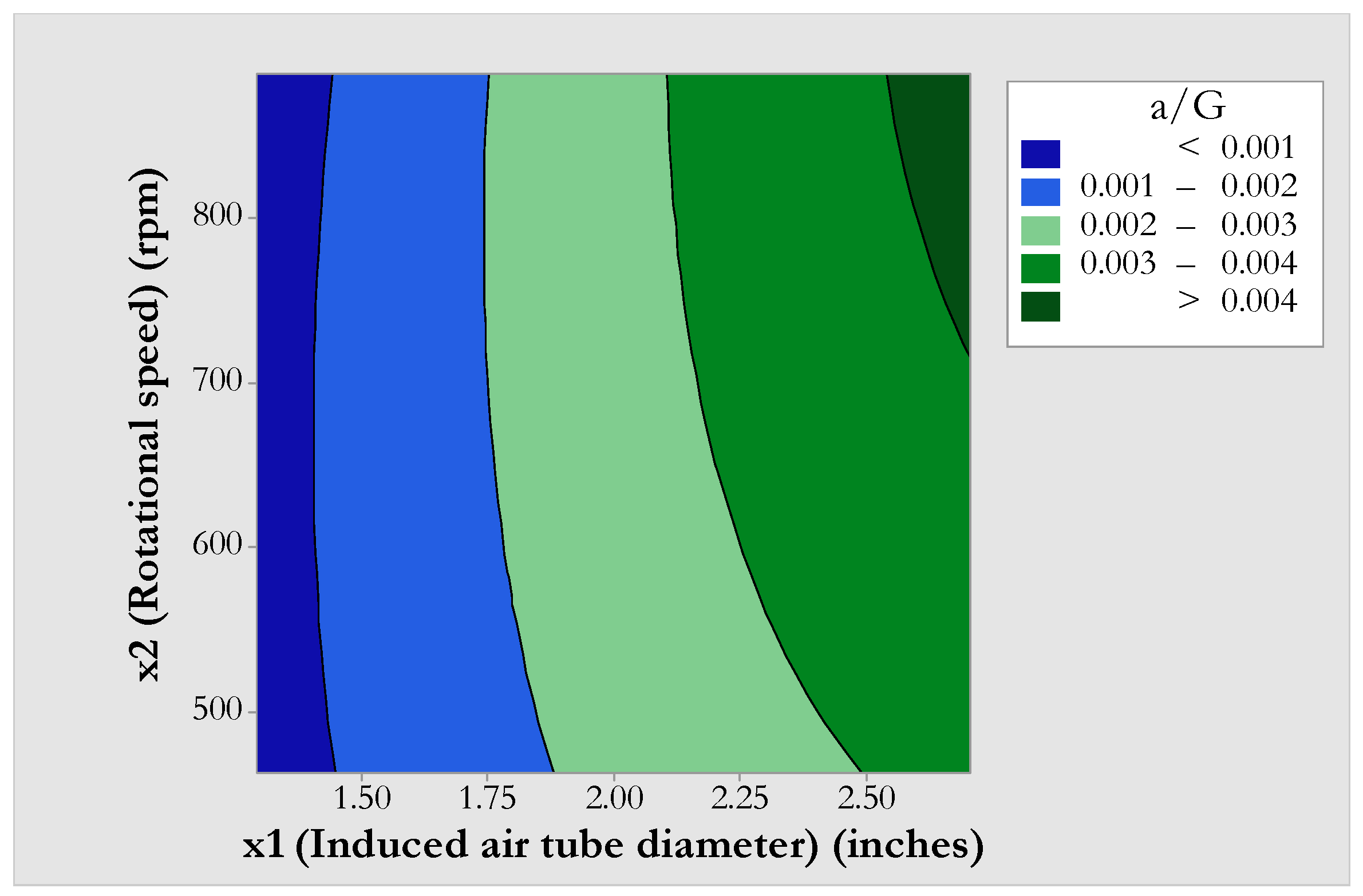
The contour plot of a/G as a function of the induced air tube diameter and rotational speed was used to demonstrate the optimal conditions that produce the suitable a/G (
Figure 3).
Based on the desirability function in RSM-CCD, as shown in
Figure 3, it could see that operating the modified IAF with a larger induced air tube diameter (in the range between 2.5 and 2.75 inches) and rotational speed (in the range between 675 and 900 rpm) resulted in a greater a/G value (>0.004). The reason was that the increase in induced air tube diameter provided a greater flux of air. Likewise, the increase in rotational speed produced a greater centrifugal force, which increased the amount of air introduced at the top and at the bottom of the liquid. The gas and liquid become fully intermingled and, after passing through a disperser outside the impeller, form a multitude of air bubbles [
24]. Additionally, the increase in rotational speed produced more shear force, which led to higher G and higher a due to the decrease in bubble size. Therefore, the operational condition with the suitable induced air tube diameter and rotational speed could enhance the a/G value.
3.3. Impact of Hydrodynamic Parameters on the Effectiveness of Plastic Separation
In order to investigate the effects of the hydrodynamic parameters in terms of a/G on the plastic separation efficiency, three operational conditions varying a/G values were used in this section; (1) low a/G (x1 of 1.50 inches, x2 of 525 rpm with providing a/G of 0.0008 s/m), (2) middle a/G (x1 of 2.00 inches, x2 of 675 rpm with providing a/G of 0.0026 s/m), and (3) high a/G (x1 of 2.75 inches, x2 of 675 rpm with providing a/G of 0.0044 s/m). To alter the surface properties of the mixed plastics, 25 g of each PS and ABS were first conditioned with 5 mg/L of tannic acid for 15 min. The conditioned plastics were then added to the system containing 2.5 mg/L of polyoxyethylene (5) lauryl ether as a surface tension modifying agent. The flotation and separation times were 2 and 3 min, respectively. Subsequently, the separated plastics were recovered and were then dried at room temperature prior to determining the plastic separation efficiency.
From the observation, most of the PS was found to be floating on the medium’s surface, whereas most of ABS was discovered to be remained at or submerged at the medium’s bottom. This was because the surface wettability properties of plastics were altered by the wetting agent. Conditioning with tannic acid could preferentially adsorb on the ABS surface [
25]. This led to the increase in hydrophilicity of the ABS surface. Therefore, PS and ABS could be separated.
The results in
Figure 4 show that a/G, apart from the chemical agents, was a significant factor affecting the effectiveness of plastic separation. Great plastic separation was achieved at a high a/G value. In high a/G conditions, PS could recover as the floated products at 89.32% with a purity rate of 94.45%, whereas ABS could recover as the sunken products at 94.76% with a purity rate of 89.88%. On the contrary, PS and ABS could recover at only 67.81% with a purity rate of 90.55% and at 92.93% with a purity rate of 74.28% under low a/G conditions. It confirms that the plastic separation could be improved at greater a/G conditions. Furthermore, the distributions of the plastic particles and chemical agents were improved by a mixing device to produce suitable turbulence as well as fine bubbles. A pitched-blade turbine, which was applied as an impeller in this study, provided an axial flow regime or top-to-bottom mixing. This type of regime led both plastic particles and bubbles to be re-circulated in the reactor [
26]. Therefore, this modified IAF process with a mixing device was feasible for handling large loads of the mixed plastics with substantial bubbles and great plastic distribution, improving the plastic separation efficiency.
4. Conclusions
In this study, the influences of design and operational factors on the bubble’s hydrodynamic and mixing parameters in IAF with a mixing device, as well as on the overall plastic separation efficiency, were investigated. Based on the statistical results of the design of the experimental method, the diameter of the induced air tube and the rotational speed were found to be the significant factors affecting the generated bubble size. The increase in the induced air tube diameter, together with the rotational speed, could generate a smaller bubble size. This was due to the fact that a greater mass flow rate of air could be introduced into the system more easily through the large tube thanks to the strong centrifugal force produced at a higher rotational speed, which was then broken into a multitude of fine air bubbles by the shear force produced at a high rotational speed. The operational condition with the suitable induced air tube diameter and rotational speed could thus enhance the a/G value. The experimental results also verify that the plastic separation performance could be improved at greater a/G conditions. At the following operational condition, induced air tube diameter (2.75 inches), rotational speed (675 rpm), polyoxyethylene (5) lauryl ether (2.5 mg/L) and tannic acid (25 mg/L) with a conditioning time of 15 min, PS could recover at 89.32% with a purity of 94.45%, whereas ABS could recover at 94.76% with a purity rate of 89.88%. Consequently, the a/G ratio was one of the key factors influencing plastic recovery other than the chemical agents (e.g., surfactant or NaCl). These findings suggest that operating the modified IAF with a mixing device at suitable a/G conditions could be a promising technique for separating the mixed plastics, which have analogous physicochemical characteristics.


 and
and 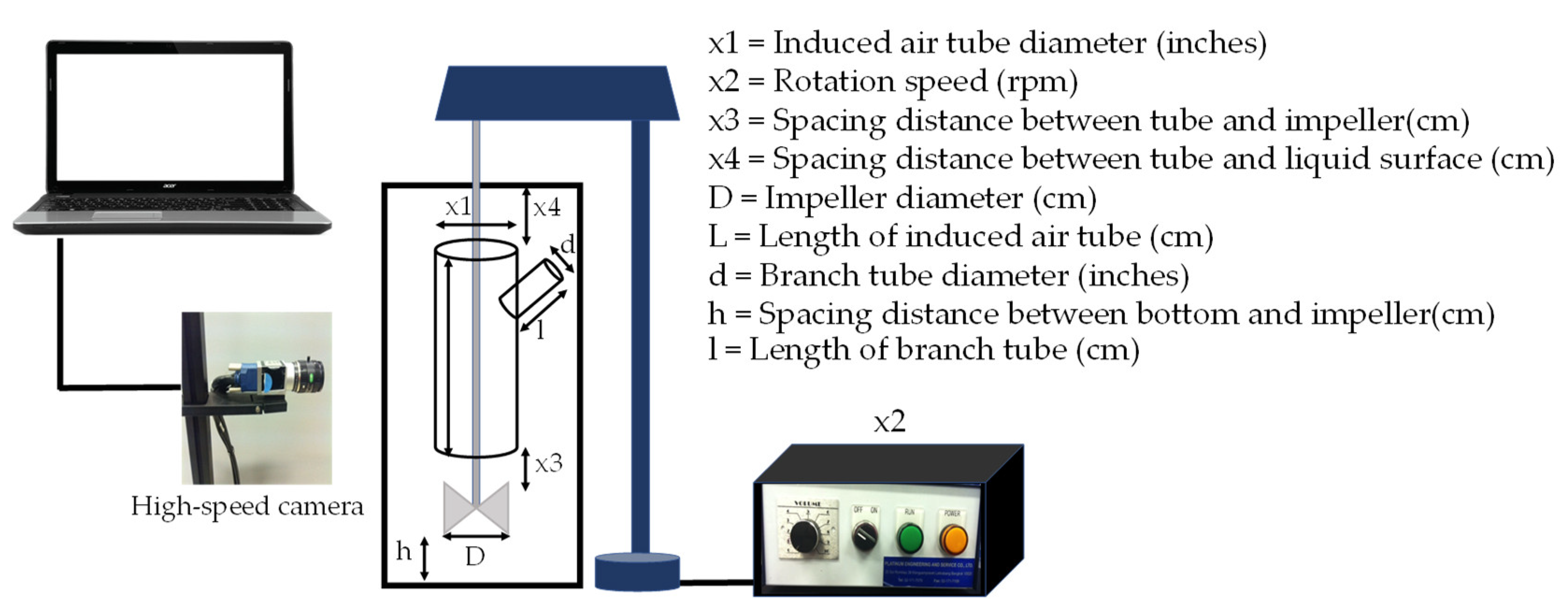

