Article

Evaluating the Thermal Behavior of a Sustainable Room and Roof Prototype Using Recycled Waste Materials

by
Flavio Roberto Ceja Soto
1,
José de Jesús Pérez Bueno
1,*,
Maria Luisa Mendoza López
2,
Martha Elba Pérez Ramos
2,
José Luis Reyes Araiza
2,3,
Rubén Ramírez Jiménez
3 and
Alejandro Manzano-Ramírez
4
1
Centro de Investigación y Desarrollo Tecnológico en Electroquímica, S. C., Parque Tecnológico Querétaro-Sanfandila, Pedro Escobedo, Querétaro CP 76703, Mexico
2
Tecnológico Nacional de México, Instituto Tecnológico de Querétaro, Av. Tecnológico s/n Esq. M. Escobedo Col. Centro, Querétaro CP 76000, Mexico
3
Facultad de Ingeniería, Centro Universitario Cerro de las Campanas, Universidad Autónoma de Querétaro, Querétaro CP 76010, Mexico
4
Centro de Investigación y de Estudios Avanzados del Instituto Politécnico Nacional, Unidad Querétaro, Libramiento Norponiente #2000, Fracc. Real de Juriquilla, Santiago de Querétaro CP 76230, Mexico
*
Author to whom correspondence should be addressed.
Recycling 2020, 5(1), 2; https://doi.org/10.3390/recycling5010002
Submission received: 19 December 2019 / Revised: 4 February 2020 / Accepted: 5 February 2020 / Published: 8 February 2020

Abstract

:
This work shows a proposed room prototype and its thermal behavior evaluation. The room was built by using polyethylene terephthalate (PET) bottles filled with soil from the site for its walls and a roof made of multiple layers of reused materials. The construction had a green roof and skylights that were constructed out of upcycled entire glass bottles. Thermal measurements were made indoors and outdoors over the course of one year. Temperature and humidity sensors were used for internal measurements, and, at the same time, a reference sensor recorded data that corresponded to external environmental conditions. The constructed building differed by an average of 8.5 °C from the reference measurements of the external environment and an average of 24.24% in relative humidity. Thermograms were taken from the outside walls, which reached 54.2 °C, while internal wall temperatures reached 25.5 °C. Additionally, a thermal transfer simulation of the prototype was accomplished by using COMSOL Multiphysics. Simulation results approximated the experimental data. The prototype had low daily thermal fluctuations, which was considered a desirable thermal behavior. These results, along with the self-building practices, low costs, and reuse of waste materials, makes this kind of building a potentially feasible alternative.

Graphical Abstract

1. Introduction

Nowadays, the building industry is one of the more active and fast-growing economic sectors; however, at the same time, it is facing a growing sustainability problem [1]. Conventional construction is definitely not sustainable adversely affecting the environment. Nevertheless, the demand outstrips supply in this market, and examples of low quality and unsuitable constructs for inhabitants exist. Due to this multi-faceted problem, there is not a unique or definitive solution; instead, and there are many developing alternatives, the key topics of which are design and construction materials [2,3,4].
Today, it is common to build mass housing projects or neighborhoods with the use of precast and economical materials. This strategy allows for industrial construction, lower costs, and high production quantities, but not enough of any, regardless of the necessities. Building materials are used interchangeably in different regions without consideration for local needs.
We are far from systematically considering factors such as climate change at the time of building. It is of vital importance to avoid contributing to its increase. Factors such as design and materials can directly affect inhabitants with more frequent extreme temperatures inside houses. This, in addition to increasing bills, also increases the use of fossil fuels, and a vicious circle comes into being.
Analyses of indoor and outdoor conditions have frequently been used to study thermal insulation that can be attained with building materials [5,6,7,8].
Green roofs have been gaining prominence both for their effect of increasing inhabitants’ comfort and fight the heat island effect in urban environments [9,10,11,12,13]. Storage capacity and evapotranspiration are considered to be some of the key factors in green roofs [13].
Research on thermal comfort has been taking the relative humidity (RH) into account as a second factor because it can influence inner thermal behavior. In some areas, high temperatures correspond to low relative humidities and vice versa. Many studies have been conducted to establish the relationship between these two factors, construction materials and the internal environment [14,15,16].
An excellent tool to analyze the behavior of any new material or construction design in advance is to conduct a thermal simulation. This simulation may allow for the matching of viable construction materials on the site and construction design with environmental conditions in the zone. These thermal simulations have allowed for the prediction of internal temperatures in buildings because they allow for the knowledge of the materials, design and external environmental conditions [17,18,19].
Polyethylene terephthalate (PET) has been among the most frequently recycled materials, and it mainly comes from soft drinks bottles [20,21,22,23]. The majority of the reported works of PET for construction have transformed the raw PET bottles into fibers, pieces, chucks or powders, which allow for the formation of composite materials [24,25,26,27,28,29,30,31,32,33,34,35,36].
PET wastes have been combined with other wastes to be used in asphalt concrete [29,30]. Many such works have focused on the effect of particle size and distribution [26,29]. Frequently, particle sizes are about 1–5 mm or in the range of 0.1–1 mm. Arulrajah et al. [26] used polyethylene terephthalate (PET) to stabilize cement blends by using a maximum PET size of 5 mm. Recycled concrete aggregate (RCA), crushed brick (CB), and PET pieces <5 mm were used as a pavement construction material [26]. Another important parameter in such composites is moisture content. Improvements in resulting characteristics have been obtained in the range of 2–4.5%wt [29]. When round particles have been used, better results have been obtained with finer particles. When fibers or long pieces have been used, better results have been obtained with longer pieces.
PET has been combined with other polymers such as polyacrylonitrile (PAN) in making fibers for composites to improve the mechanical and durability characteristics of concrete and mortars [27].
Uses other than concrete blends include chemical (glycolysed) [34] or thermo-mechanical recycling together with incineration. These are downcycling procedures and require energy, transportation, storage in large areas of land, and the use of chemicals that entail economic, environmental, and safety issues.
COMSOL Multiphysics has been used in many different simulations [37,38,39,40,41]. In the case of engineering, specifically in the construction area of research, Guo et al. [38] used it to simulate the multi-species transport of saturated cement-based materials. Wei et al. [39] used it to simulate concrete as a three-phase composite made of aggregates, interfacial areas, and mortar. The diffusion of chlorine ions was investigated by Maliki et al. [40], who used it to model heat, air, and moisture in porous media and applied it to assess the hydrothermal performance of structural building components. Their results showed that an insulated wall had only a quarter of the total heat flux of an uninsulated concrete roof. Sharifi et al. [41] used COMSOL to simulate temperature changes of a concrete specimen containing phase change materials (PCMs) under typical meteorological year data.
This work reports the evaluation of a prototype that was built with walls made of entire PET bottles and mortar, as well as a roof made of multiple layers of reused materials with a top vegetal layer. This work gives a detailed construction procedure, the waste materials used, the changes proposed to embed the walls by using filled or empty bottles, and the roof multi-layered strata, all of which make this paper differ from a previous work that focused on proposing metrics for measuring the sustainability of houses by using the prototype as an example for calculating the number associated with its sustainability according to the proposed metrics [42]. The prototype was monitored over the period of a year; the measurements of its behavior were hydrothermal. A thermal simulation of the material/design behavior of the prototype was accomplished with the COMSOL Multiphysics software. Thermal images were taken for comparison with thermal simulation, internal temperatures and heat conduction through the walls of the building.

2. Materials and Methods

A prototype room was constructed while making necessary adjustments in methodology for incorporating entire PET bottles into walls and recycled materials into a multi-layered roof. The prototype was located at Sanfandila, Pedro Escobedo, Queretaro, Mexico [20°29′26.78″N, 100°13′19.98″W] with its facade pointing toward the northeast (NE). All the figures in this work include an arrow indicating orientation.

2.1. Construction of Room Prototype

The procedure for the construction consisted of eight stages: I. Stonemasonry foundations and reinforced concrete columns; II. PET bottle filling with soil; III. the construction of PET bottle walls; IV. confinement perpendicular to the walls; V. wrapping with galvanized wire nets; VI. covering walls with mortar; VII. area for skylights; and VIII. multi-layered roof.

2.1.1. Stone Masonry Foundations and Reinforced Concrete Columns

The stone masonry foundations were constructed in a traditional manner according to the local soil characteristics.

2.1.2. PET Bottle Filling with Soil

The PET bottles used in the walls of the prototype room were filled with clayey soil from the site. After filling the bottles, the clay was rammed with a hammer and a wedge for tightening in each bottle. These were then tightly capped. The number of PET bottles used for the walls was estimated to be around five thousand.

2.1.3. The Construction of PET Bottle Walls

The PET bottles were positioned horizontally, as shown in Figure 1a. The bottles were placed to form rows, with each alternating top and bottom. This provided a more stable stack. Additionally, complete rows with bottles aligned in the same direction facilitated the placement of the electrical wiring. The lateral stability of the walls was attained with reinforced concrete columns.

2.1.4. Confinement Perpendicular to the Walls

The proposed confinement of the walls provided lateral stability. The confinement consisted of horizontal rebar that was anchored to the concrete columns and moored with two different gauge wires, which had a separation distance of around 0.5 m (Figure 1b). Each wall had five rows of rebar per side. The northeastern side (facade) was an exception due to the window and door. This led to a second proposed confinement of the walls by using reinforced concrete elements, which in this case were door/window columns.

2.1.5. Wrapping with Galvanized Wire Nets

The galvanized wire nets were moored to the horizontal rebar on both sides of each wall (Figure 1b). This was done to increase the confinement of the PET bottles in a direction that was perpendicular to the wall.

2.1.6. Covering Walls with Mortar

The PET bottle walls were completely covered with mortar. The mortar was prepared with Portland cement, lime, and well-graded sand, with the proportion of cement increasing along with the strength requirements. Composed Portland Cement CPC-30R (minimum compression strength of 20 N/m2 and 30 N/m2 for 3 and 28 days, respectively [43]) and commercially available hydrated lime (Ca(OH)2) were used as chemical additives in all the mortar mixes. Additionally, mine sand with a fineness modulus of 2.44 and a specific gravity of 2.65 was used as a fine aggregate. This met the grain size specified in the ASTM International C33/C33M-18 standard [44]. The mortar mixtures were prepared under the ASTM C109/C109M-16a standard [45], and the proportions of materials for the standard mortar were 1.25 parts cement-hydrated lime to 2.75 parts graded standard sand by weight. The quantity of water, measured in milliliters, was used to produce a flow of 110 ± 5, as determined by the test method of ASTM C 109/C109M-16a [45].
A complete filling of the voids, caused by the narrow bottlenecks, was not intended and could be costly. On the contrary, empty spaces were preferred as a thermal barrier. The galvanized wire net was helpful in easily achieving a flat surface. The use of paint was not desired due to its influence on thermal behavior. Thus, a final layer of white cement with white marble powder was used to create a white finish. The overall increase of wall thickness was about 5 cm per each side, additional to the length of the bottles (23.5 cm). This implies that the walls were about 33 cm in thickness.

2.1.7. Area for Skylights

A single row of used glass bottles was placed at the top level of the internal room as a skylight for natural daylight and for natural ventilation through the empty space between each bottle (Figure 1c). Since the walls were unusually thick, a configuration with two aligned bottles was used. This allowed us to place their bottoms as the outer side, which provided a flat and regular surface on the internal and the external sides of each of the three walls. The natural ventilation was obstructed or opened according to the type of test that was conducted.

2.1.8. Multi-Layered Roof

The roof implemented in the room prototype consisted of a metallic base for structural support and various layers of recycled or, more precisely, upcycled materials used as found without further processing.
The metallic base consisted of six tubular steel profiles of 2″ square hollow sections. Three corrugated galvanized sheets were mounted in an area of 3 × 3 m. The three sheets were placed matching ridges with valleys and were perpendicular to the steel supports (Figure 1c). Their borders coincided with the middle of the wall, and they were embedded in a surrounding 25 cm high and 15 cm wide concrete wall. Two PVC pipes were placed to allow for the drainage of excess rainwater.
Figure 1d shows the roof insulating layers, which were composed of used plastic bags, two layers of uncapped PET bottles of different shapes and sizes, another layer of plastic bags, used cardboard, soil from the site (expansive clay containing montmorillonite), and an endemic plant top layer.

2.2. Measuring External and Internal Climatic Conditions: Humidity and Temperature

2.2.1. Internal

The measurements of temperature and humidity were carried out with Thermotracker brand sensors. Two internal sensors were installed in the prototype, one at middle height on the northwestern wall and the other in the middle of the door and window. The reference temperatures were recorded from three places: (A) One located in a nearby building under a roof without walls and protected from direct sunlight and rain, (B) another placed under similar conditions but in a house in the area, and (C) one located inside that house with a permanently open window. There was a very close correspondence between these measurements, so the former sensor data were chosen as the reference. This reference was placed in a neighbor structure covered by a roof but without walls, so it had ventilation and daylight without being directly exposed. The restrictions for placing both sensors were to avoid direct exposure to sunlight and rain throughout a year-long period.
The position of the sensors allowed for the recording of air temperatures—except for surface temperature, which was complementarily measured with thermograph images—for extended periods of time.
Data were taken for an annual cycle, and the information was accessed through the Thermotracker Pro software. Data points were typically recorded 72 times a day for both temperature and relative humidity (RH).

2.2.2. External

(a) Thermograph images were taken with a thermal camera, PCE Instruments® model PCE-TC 3. The images showed contrasts according to surface emissivity and temperature, which in part depended on the absorption and thermal conductivity of materials. The thermograms showed the maximum temperatures reached on the outside walls. These were taken at the peaks of heat concentration, which were around 12:00 p.m. and 3:00 p.m.
(b) Humidity on the surface. The humidity study was carried out with the aid of a humidity meter for building materials, PCE Instruments® model WP-21. The measurement result was the average humidity value calculated at 50 mm above the surface. Measurements were taken on external sides of prototype walls, with a distance of 50 cm between each measurement.

2.3. Simulation of Thermal Transference at the Prototype Building

The simulation was accomplished with the COMSOL Multiphysics 3.5 software by using the heat transfer module. The steps used were as listed:
  • Geometrical details of room prototype. This could be drawn within the software or imported from other specialized design software.
  • Specification of conditions of each subdomain from the prototype to be evaluated, in this case: walls, windows, doors, roof, and foundations. Table 1A shows each condition used.
  • Specification of boundary and initial conditions for the structure. The room was sectioned into parts as necessary to establish different conditions. The specifications are shown in Table 1B. These boundary conditions were chosen in part based on characteristics of the prototype and, in part, based on thermal images and other measured properties or dimensions.
  • Setting temperature and average radiation of the areas.
  • Solving the simulated system.
Part of the simulation was conducted by supplying additional information that COMSOL’s library did not contain, such as the thermal conductivity of the PET walls. The outside temperature was set at 27 °C, and the average solar radiation was considered to be 5.2 W/m2.

3. Results and Discussion

3.1. Temperature and Relative Humidity

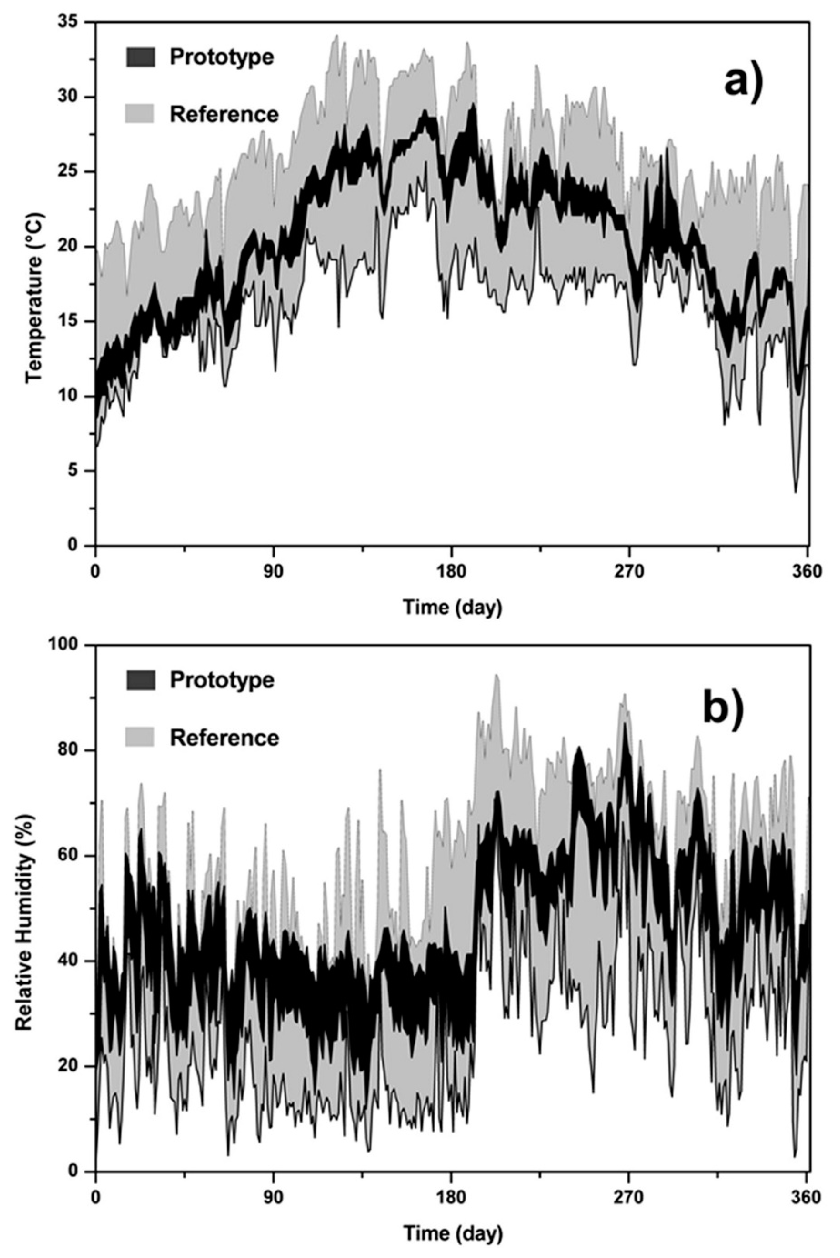
Measurements of temperature and RH were taken along an annual cycle (December 2010–December 2011) within the PET bottle prototype. Data were registered by the sensors every 20 min. Figure 2 shows only the higher and lower values per day to plot all data in a comprehensible way. Figure 2a shows the temperature data, where a light gray background area only indicates the maximum and minimum temperatures per day of the reference sensor, with the complete range representing the fluctuation per day over one year. The dark area indicates the inner recording by the sensor. Figure 2b shows the RH data with, again, the light gray background area indicating the reference sensor information and the dark area indicating the inner recording by the sensor.
The average temperature gradient, during a one-year period, between the external environment and within the prototype was 8.08 °C, according to Figure 2a,b. The lower temperatures corresponded to winter, primarily in December, and the higher temperatures to spring/summer, primarily in May/June. The graph of annual temperatures was nearly a Gaussian graph in the region where the PET prototype was built. The equation used was:
y = y 0 + A w π 2 e 2 x x c w
where y0 is the offset, A is the area (≥0), w is the width, and xc is the position of the center of the peak. The parameters of Gaussian fittings for each graph in Figure 2a are shown in Table 2. The areas of prototype maximum temperature (P-Tmax (1)) and minimum temperature (P-Tmin (2)) were 7743.8 and 7028.1, respectively. Meanwhile, the areas of reference maximum temperature (R-Tmax (3)) and minimum temperature (R-Tmin (4)) were 9367.1 and 5799.4, respectively. The comparison was carried out by subtracting these areas as (Area 1 − Area 2) = 715.7 and (Area 3 − Area 4) = 3567.7. Then, the ratio (1 − 2)/(3 − 4) = 0.2. This implies that the attenuation of fluctuations throughout one year of the PET complete bottle prototype and its surroundings was approximately one fifth. This value was not relative to another conventional room but to the environment, considering the external but covered position of the reference sensor.
The range changed under different conditions of relative humidity, presenting a difference of 9.27% HR (humidity ratio) at high humidity conditions and a difference of 14.97% HR in an environment of low humidity. Therefore, the average relative humidity insulation was 24.24% HR, according to Figure 2b.
There was a relatively stable low humidity season at around days 90 and 190. The abrupt change was associated with a season of rain that commenced on day 192 and lasted until day 355. The complete PET bottle prototype had passive natural ventilation through lines of empty glass bottles, which protruded 5 cm from the external side. This was intended in part to conduct daylight into the room. This was also a result of accommodating a series of two complete glass bottles whose bottoms were directed to the outside to constitute skylight lines. The round complete glass bottles left empty spaces between them, which were used as passive ventilation (Figure 1c). These tunnels could be closed at will. Usually, this task could be done with a fabric or a curtain. Nonetheless, in this case, it was done with used polyethylene bags in order to ensure a tight blockage to airflow.
The ventilation was kept open during the autumn-winter period and closed for spring and summer. This was done to allow for knowledge of the results of extremes in the internal environment because a normal procedure would usually be the opposite in order to regulate indoor conditions. The indoor relative humidity was usually closely related to the external relative humidity during the autumn-winter period when ventilation was kept open. The dark area of RH in Figure 2b is only thicker for the low humidity season, at around days 90 and 190.

3.2. Thermograph Images and Humidity on Surfaces

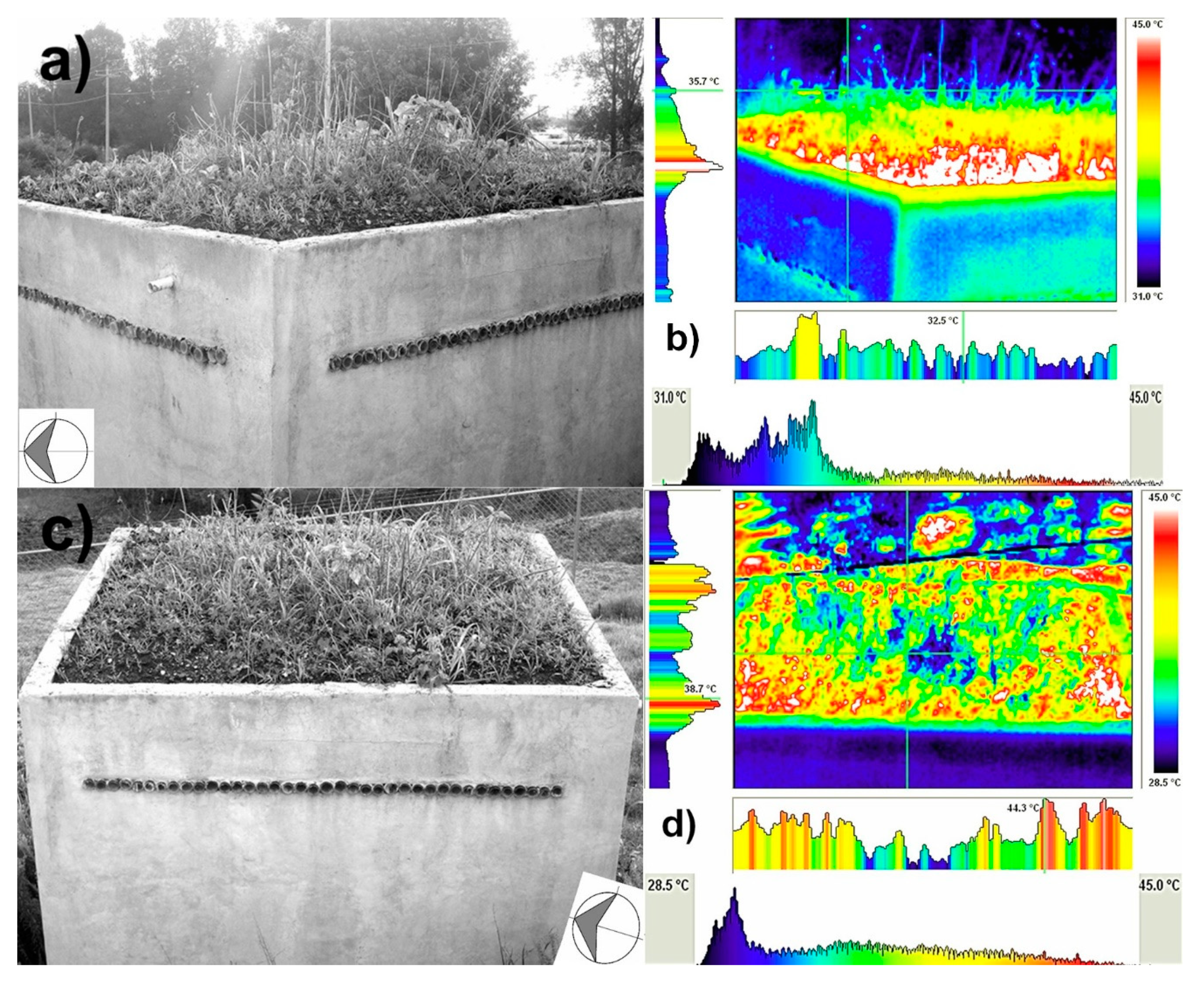
Thermograph images were taken of the outer and inner parts of the prototype room. The images showed stable external behavior in the different areas of the prototype. Figure 3a shows an image of the facade and southeastern wall. Complementarily, from the same point, Figure 3b shows a thermogram (taken on 24/08/2011 16:05, with 26 °C, RH 32%). The colder parts are represented as dark areas, and the hotter parts are represented in white. The dark glass used as the window and door maintained an outer temperature of around 47 °C. Figure 3c shows the rear with the northwestern wall under sunlight and an overshadowed southwestern wall. Figure 3d shows a corresponding thermogram (taken on 27/05/2011 11:45, with 30 °C, RH 26%). There was an average temperature of around 45 °C. Nevertheless, the temperature distributions were not uniform. The change in the wall temperature was associated with the heterogeneous distribution of humidity that was kept on the wall because of dissimilar finishing at different areas.
The thermograms show a bar scale on their right. They show temperature profiles that correspond to a horizontal and a vertical line, located at their right and under them. These temperature profiles indicate the highest temperature observed. Additionally, a histogram of the temperature distribution of the image is located at the bottom, which shows lower and higher temperatures in the covered range. This kind of representation intends to show, with more detail, temperature fluctuations in these images.
The humidity varied between 0.5% and 1.3% in the external parts of the walls at noontime. Other measurements were taken in buildings nearby the PET prototype room, and the data differed between 4% and 13.5%.
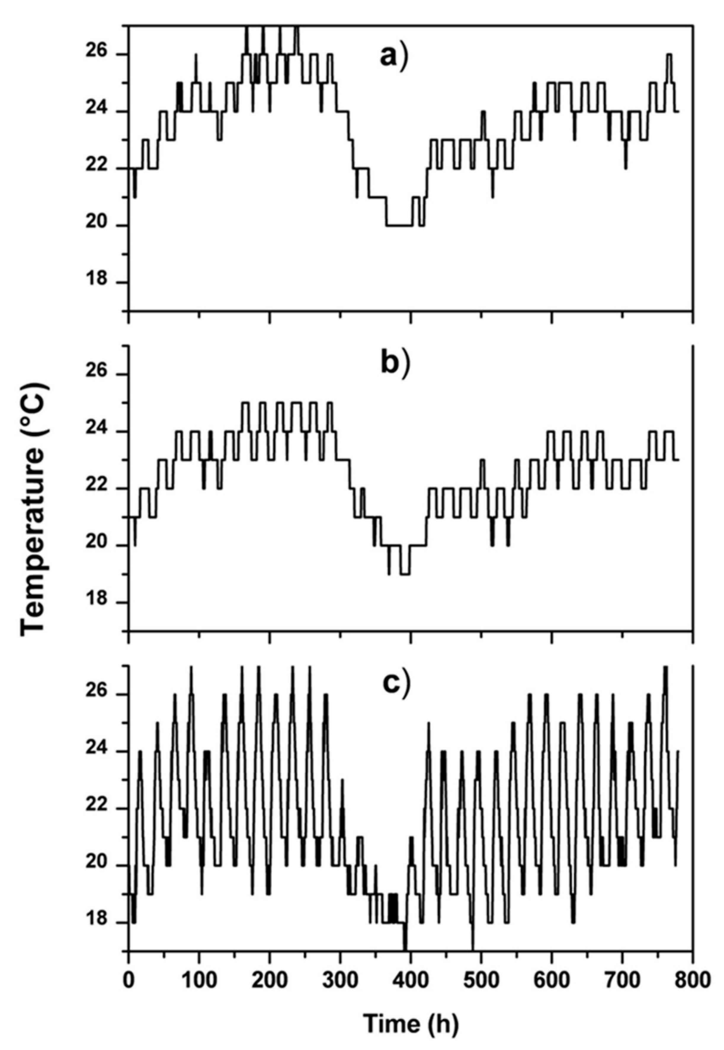
The green roof had the highest temperature, reaching up to 71 °C. It is important to highlight that the high temperature was only on the roof soil surface because, at the level of the two layers of complete and uncapped PET bottles, the temperature remained very stable, night and day, throughout the year. This is shown in Figure 4a–c, which show temperature recordings during a short period of one summer month. Figure 4a shows the air temperature that was measured with a sensor that was located inside the prototype room at the roof level on the southwestern wall. Figure 4b shows the temperature data from a sensor inside the multi-layered roof, located in the double layer of the empty, opened PET bottles. Figure 4c indicates the air temperature from a reference sensor that was located as described previously.
The roof images and their thermograms are shown in Figure 5a,b and Figure 5c,d, respectively. The thermograms were taken in May–June, with warm weather in the area (Figure 5b was taken on 27/05/2011 11:46, by 30 °C RH 26%, and Figure 5d was taken on 03/06/2011 11:41, with 25 °C, RH 31%). During this month, the prototype presented a maximum internal temperature of 30 °C. Again, the thermograms show a bar scale on their right. They show temperature profiles that correspond to a horizontal and a vertical line, located at their right and under them. A histogram of the temperature distribution of the image is located at the bottom and depicts its temperature range.
The average temperature of the outside walls was about 45 °C, and the maximum temperature of the inside walls was about 26 °C (Figure 3b,d). Complementarily, the thermal difference between the internal and external environment was about 8 °C.
The window and door were the prototype’s colder and hotter parts due to the aluminum foil that was externally placed to prevent direct heating by reflecting solar radiation (Figure 3b). The different parts of the prototype demonstrated similar temperatures, except the northwestern and the northeastern zones. The structure temperature was predominantly uniform everywhere.
Figure 3d shows some white areas and spots that had higher wall temperatures. This was persistently observed and probably originated in the construction stage due to the different top coating in that area. Due to such differences, there were some areas that accumulated humidity at the southeastern wall during the rainy season. This was evident in some thermograms, showing up as colder areas. The same occurred at the outer sides of walls at the roof level, where temperatures were consistently lower during the rainy season due to humidity accumulated on the roof.
The roof surface showed high temperatures that were similar to ground temperatures because the soil and vegetation were used to cover the structure as a green roof (Figure 3b). In part, this is an objective of a green roof, which mimics the surroundings from a top view. The inside of the green roof was stable, however, due to isolation by multiple layers that were made with recycled materials that were placed above a galvanized sheet. The soil and vegetation on top gave additional thermal coverage, but direct exposure of the dark soil increased the sunlight absorption.
The humidity differences between the PET prototype and some nearby constructions arose from the building’s size, design, weather conditions and sunlight illumination on each side, among other factors. The PET prototype was isolated from other constructions. Additionally, it was made of a single floor and without a shed structure, which increased its exposure to sunlight and reduced its humidity retention. On the other hand, its design with a green roof maintained humidity, which was evident with lower temperatures at the outer sides of the walls at the roof level. Consequently, these results corroborate that the surface humidity of the walls was significant in modifying their temperatures and that the roof humidity influenced the room’s thermal behavior. Thus, there was a direct dependence between the surfaces’ humidity and their external temperatures.

3.3. Heat Transfer Simulation by COMSOL Multiphysics

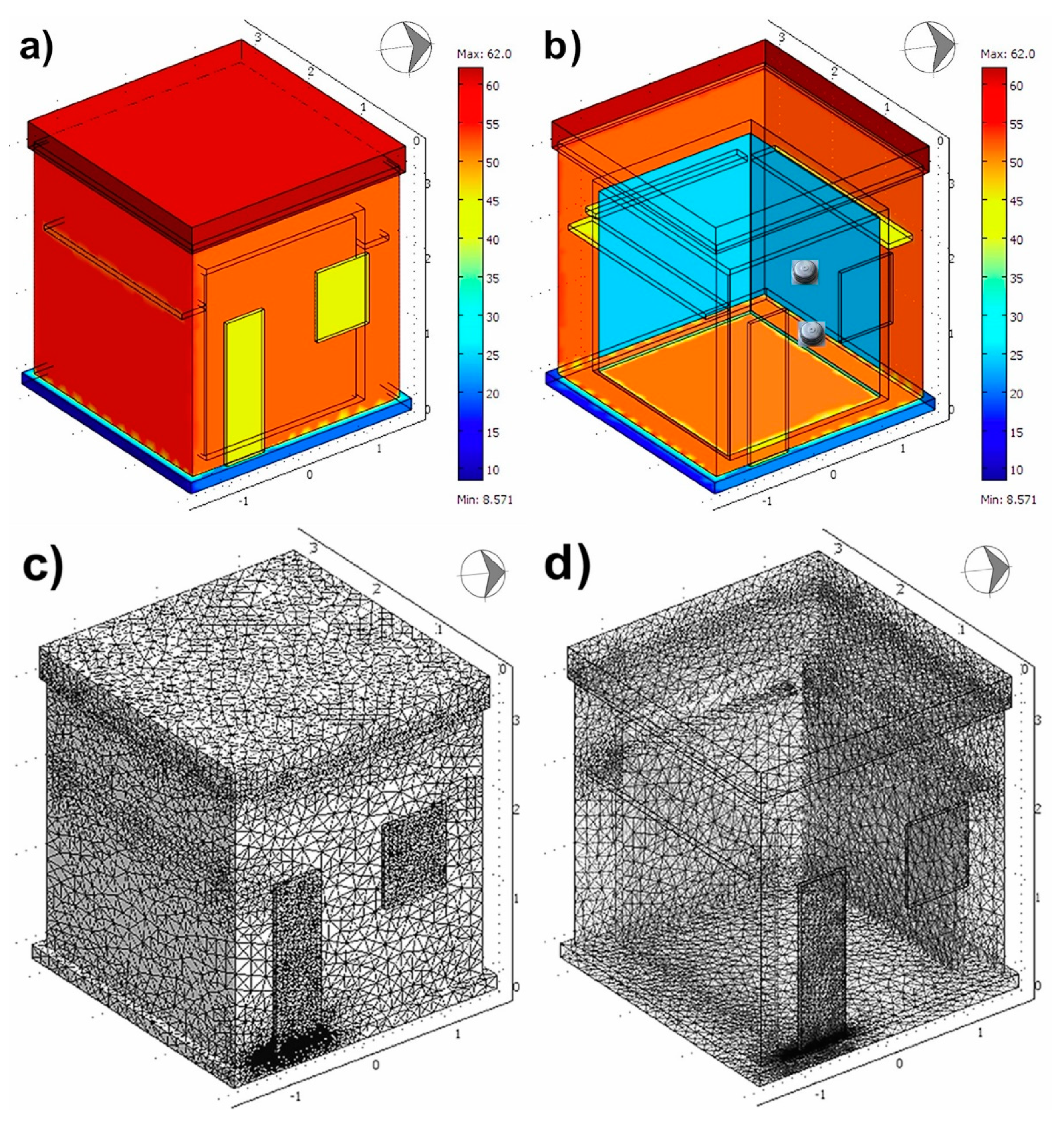
Figure 6a shows the simulated possible outer wall behavior of the prototype room. The scale of the three axes is in meters. The temperature ranged from a minimum of 8.5 °C (on the floor) to a maximum of 62 °C at the top of the room. The temperature of the glass areas on the door and window reached 45 °C. Complementarily, the rest of the door and window reached about 40 °C. The foundations were in the range of 10 to 20 °C. In Figure 6a, we can observe the dispersion of heat between the different materials of the prototype. Figure 6b presents an internal view of the thermal behavior of the simulated prototype room. The internal environment was in the range of 22 to 23 °C.

3.4. Heat Transfer Simulation by COMSOL Multiphysics

The general objective of conducting a simulation arose from the usefulness of having a model that well-represents physical construction and, in that way, approximates thermal behavior under extreme weather conditions. The aim of this work was limited to obtaining a model that matched the observed experimental thermal behavior by using experimentally measured variable values. The simulation performed well despite some parts of the room sketch that were not differentiated. For example, the roof was registered as only one domain; for this reason, the roof presented a uniform behavior. The same occurred in other parts of the prototype. However, the simulation was considered a first step in visualizing temperature distributions when further changes may be introduced, e.g., the painting or waterproofing of walls, using plants with dense foliage on top, trees growing alongside the building, changes in the door or window, or long-term changes in weather caused by global warming.
The outside of the walls in the simulation had similar behavior to real the thermal images presented in Figure 3b,d. The simulation varied at around 4 °C compared to the measurements that were recorded in the thermograms. The inside of the walls in the simulation had a variation of about 2 °C compared to thermograms.
The simulation started with values for some parameters that were taken from experimental observations. The experimentally observed thermal transference, including heating by sunlight radiation and internal air temperature, was represented in the simulation. Some material properties were directly taken from the software library and applied to all zones that had such materials. The fluctuation of real building material properties was a difficult variable to control since construction was conducted following a traditional methodology as much as possible. A direct comparison between the outside wall surfaces and those of the simulation patterns showed differences in real temperature patterns and gradual fluctuations, respectively.
Finally, there were correspondences between the observed and final simulation values. Nonetheless, they were roughly similar considering all those conditions that were not possible to include in those conducted simulations.

4. Conclusions

Thermal behavior was evaluated for a prototype room that was constructed with walls based on complete PET bottles and a green roof with multiple layers of recycled materials. The prototype demonstrated regulated temperatures and good thermal insulation when comparing internal and external environments. Indoor variations were within the range of 0.5 to 3.4 °C per day, while outside variations were approximately 16.5 °C.
The external behavior of the PET prototype room was uniform, keeping maximum temperatures of around 45 °C at the walls. The construction materials demonstrated good insulation. Specifically, the roof design and materials allowed for thermal isolation and mimicked the surroundings.
The temperature was raised to 30 °C indoors (26 °C at walls) as a maximum and was purposely decreased to 10 °C by blocking the ventilation. The green roof with black soil showed a maximum temperature of 71 °C. This was only on the surface, which is noteworthy. The roof maintained very stable temperatures day and night, the whole year, at the level of the two layers of the complete and uncapped PET bottles.
The PET prototype design with a green roof maintained humidity, which was evident with lower temperatures at the outer sides of walls at the roof level. Consequently, these results corroborate that the surface humidity of the walls was significant in modifying their temperatures and that roof humidity influenced the room’s thermal behavior.
The uneven temperature distribution at the side walls was attributed to non-visible fluctuations during construction, consistently causing hot spots or areas that maintaining prolonged humidity following rain. The measurement of humidity at the walls did not show differences between hot spots and other areas.
The thermal transference simulation carried out for a sketch of the prototype dimensions achieved pleasant internal temperatures of around 22 °C. This simulation was restricted to very wide domains, which resulted in uniform behaviors in different areas. The simulation showed that the roof exhibited high temperatures that were caused by the absorption of higher solar radiation. There was a close relationship with the real prototype at the roof, with those high temperatures being superficial since mild and stable temperatures were registered in the green roof, with an average of 22.54 °C and variations of ± 2.7 °C.

Author Contributions

Conceptualization, J.d.J.P.B.; Formal analysis, F.R.C.S. and J.L.R.A.; Funding acquisition, J.d.J.P.B.; Investigation, F.R.C.S., J.d.J.P.B., M.L.M.L., and J.L.R.A.; Methodology, M.E.P.R.; Software, R.R.J.; Supervision, J.d.J.P.B. and M.L.M.L.; Validation, A.M.-R.; Writing—review and editing, F.R.C.S., J.d.J.P.B., and M.L.M.L. All authors have read and agree to the published version of the manuscript

Funding

This work was done under the auspices of the CONACyT through the projects COAH-2006-C05-62059, QRO-2010-C02-149297, QRO-2010-C02-149326, and CONACYT-SENER CEMIE-Sol No. 207450.

Acknowledgments

The authors want to thank Juan Mendoza García, Juan Pablo Pérez Ramos and Edain Belen Pérez Mendoza for their efforts and valuable contribution in the prototype building. Additionally, we want to thank M.C. Pablo Esau Hidalgo Pimentel for his helpful advice in conducting the thermal simulation. The authors are especially grateful to Eric Albert Huston of the US Peace Corps for his valuable suggestions for this work.

Conflicts of Interest

The authors declare no conflict of interest.

References

  1. Griffiths, S.; Sovacool, B.K. Rethinking the future low-carbon city: Carbon neutrality, green design, and sustainability tensions in the making of Masdar City. Energ. Res. Soc. Sci. 2020, 62, 101368. [Google Scholar] [CrossRef]
  2. Saieg, P.; Sotelino, E.D.; Nascimento, D.; Caiado, R.G.G. Interactions of Building Information Modeling, Lean and Sustainability on the Architectural Engineering and Construction industry: A systematic review. J. Clean. Prod. 2018, 174, 788–806. [Google Scholar] [CrossRef]
  3. Shan, M.; Hwang, B.-G. Green building rating systems: Global reviews of practices and research efforts. Sustain. Cities Soc. 2018, 39, 172–180. [Google Scholar] [CrossRef]
  4. Khoshnava, S.M.; Rostami, R.; Valipour, A.; Ismail, M.; Rahmat, A.R. Rank of green building material criteria based on the three pillars of sustainability using the hybrid multi criteria decision making method. J. Clean. Prod. 2018, 173, 82–99. [Google Scholar] [CrossRef]
  5. Al-ajmi, F.F.; Loveday, D.L. Indoor thermal conditions and thermal comfort in air conditioned domestic buildings in the dry-desert climate of Kuwait. Build. Environ. 2010, 45, 704–710. [Google Scholar] [CrossRef]
  6. Huang, C.; Zou, Z.; Li, M.; Wang, X.; Li, W.; Huang, W.; Yang, J.; Xiao, X. Measurements of indoor thermal environment and energy analysis in a large space building in typical seasons. Build. Environ. 2007, 42, 1869–1877. [Google Scholar] [CrossRef]
  7. Martín, S.; Mazarrón, F.R.; Cañas, I. Study of thermal environment inside rural houses of Navapalos (Spain): The advantages of reuse buildings of high thermal inertia. Constr. Build. Mater. 2010, 24, 666–676. [Google Scholar] [CrossRef]
  8. Grigoletti, G.; Sattler, M.A.; Morello, A. Analysis of the thermal behavior of a low cost, single-family, more sustainable house in Porto Alegre, Brazil. Energ. Build. 2008, 40, 1961–1971. [Google Scholar] [CrossRef]
  9. Santamouris, M. Cooling the cities—A review of reflective and green roof mitigation technologies to fight heat island and improve comfort in urban environments. Sol. Energy 2014, 103, 682–703. [Google Scholar] [CrossRef]
  10. Pradhan, S.; Al-Ghamdi, S.G.; Mackey, H.R. Greywater recycling in buildings using living walls and green roofs: A review of the applicability and challenges. Sci. Total Environ. 2019, 652, 330–344. [Google Scholar] [CrossRef]
  11. Pushkar, S. Modeling the substitution of natural materials with industrial byproducts in green roofs using life cycle assessments. J. Clean. Prod. 2019, 227, 652–661. [Google Scholar] [CrossRef]
  12. Zhang, Z.; Szota, C.; Fletcher, T.D.; Williams, N.S.G.; Farrell, C. Green roof storage capacity can be more important than evapotranspiration for retention performance. J. Environ. Manag. 2019, 232, 404–412. [Google Scholar] [CrossRef] [PubMed]
  13. Cascone, S.; Coma, J.; Gagliano, A.; Pérez, G. The evapotranspiration process in green roofs: A review. Build. Environ. 2019, 147, 337–355. [Google Scholar] [CrossRef]
  14. Arnaud, L. Comparative Study of Hygro Thermal Performances of Building Materials. In Proceedings of the 11th International Conference on Non-Conventional Materials and Technologies (NOCMAT 2009), Bath, UK, 6–9 September 2009. [Google Scholar]
  15. Zhang, H.; Yoshino, H. Analysis of Indoor Humidity Environment in Chinese Residential Buildings. Build. Environ. 2010, 45, 2132–2140. [Google Scholar] [CrossRef]
  16. Makaka, G.; Meyer, E.L.; McPherson, M. Thermal behavior and ventilation efficiency of a low-cost passive solar energy efficient house. Renew. Energ. 2008, 33, 1959–1973. [Google Scholar] [CrossRef]
  17. Garzón, B.; Raimondi, G.G. Thermal Simulation for the Improvement of Rural Popular Houses in Tucuman, Argentina. In Proceedings of the 11th International Conference on Non-Conventional Materials and Technologies (NOCMAT 2009), Bath, UK, 6–9 September 2009. [Google Scholar]
  18. Garzón, B.; Hernández, A.; Mele, E.; de Benito, L. Application of Bioclimatic Strategies, Monitoring and Thermal Simulation in a Social Rural House in Chubut, Argentina. In Proceedings of the 11th International Conference on Non-Conventional Materials and Technologies (NOCMAT 2009), Bath, UK, 6–9 September 2009. [Google Scholar]
  19. Sailor, D.J. A green roof model for building energy simulation programs. Energ. Build. 2008, 40, 1466–1478. [Google Scholar] [CrossRef]
  20. Fraternali, F.; Ciancia, V.; Chechile, R.; Rizzano, G.; Feo, L.; Incarnato, L. Experimental study of the thermo-mechanical properties of recycled PET fiber-reinforced concrete. Compos. Struct. 2011, 93, 2368–2374. [Google Scholar] [CrossRef]
  21. Foty, D. Preliminary analysis of concrete reinforced with waste bottles PET fibers. Constr. Build. Mater. 2011, 25, 1906–1915. [Google Scholar] [CrossRef]
  22. Reis, J.M.L.; Carneiro, E.P. Evaluation of PET waste aggregates in polymer mortars. Constr. Build. Mater. 2012, 271, 107–111. [Google Scholar] [CrossRef]
  23. Frigione, M. Recycling of PET bottles as fine aggregate in concrete. Waste Manag. 2010, 30, 1101–1106. [Google Scholar] [CrossRef]
  24. Spadea, S.; Farina, I.; Berardi, V.P.; Dentale, F.; Fraternali, F. Energy dissipation capacity of concretes reinforced with recycled PET fibers. Ing. Sismica 2014, 31, 61–70. [Google Scholar]
  25. Colangelo, F.; Forcina, A.; Farina, I.; Petrillo, A. Life cycle assessment (LCA) of different kinds of concrete containing waste for sustainable construction. Buildings 2018, 8, 70. [Google Scholar] [CrossRef] [Green Version]
  26. Arulrajah, A.; Perera, S.; Wong, Y.C.; Horpibulsuk, S.; Maghool, F. Stiffness and flexural strength evaluation of cement stabilized PET blends with demolition wastes. Constr. Build. Mater. 2020, 239, 117819. [Google Scholar] [CrossRef]
  27. Chinchillas-Chinchillas, M.J.; Gaxiola, A.; Alvarado-Beltrán, C.G.; Orozco-Carmona, V.M.; Pellegrini-Cervantes, M.J.; Rodríguez-Rodríguez, M.; Castro-Beltrán, A. A new application of recycled-PET/PAN composite nanofibers to cement-based materials. J. Clean. Prod. 2020, 252, 119827. [Google Scholar] [CrossRef]
  28. Ricardo, J.R.C. Use of Residues of Crushed Pet Bottles in the Form of a Scale as an Addition to the Manufacture of Concrete. In Proceedings of the International Conference of Sustainable Production and Use of Cement and Concrete; RILEM Bookseries; Springer: Cham, Switzerland, 2020; Volume 22, pp. 251–263. [Google Scholar] [CrossRef]
  29. Taherkhani, H.; Arshadi, M.R. Investigating the mechanical properties of asphalt concrete containing waste polyethylene terephthalate. Road Mater. Pavement Des. 2019, 20, 381–398. [Google Scholar] [CrossRef]
  30. Hidayat, N.; Pratama, G.N.I.P.; Pramita, I.D. The Effect of PET Plastic Addition (Polyethylene Terephthalate) and Carbide Waste Filler for Asphalt Concrete-Binder Course (AC-BC) on Marshall Characteristics. IOP Conf. Ser. Earth Environ. Sci. 2019, 366, 012024. [Google Scholar] [CrossRef] [Green Version]
  31. Zeng, J.-J.; Gao, W.-Y.; Duan, Z.-J.; Bai, Y.-L.; Guo, Y.-C.; Ouyang, L.-J. Axial compressive behavior of polyethylene terephthalate/carbon FRP-confined seawater sea-sand concrete in circular columns. Constr. Build. Mater. 2020, 234, 117383. [Google Scholar] [CrossRef]
  32. Gao, Y.; Romero, P.; Zhang, H.; Huang, M.; Lai, F. Unsaturated polyester resin concrete: A review. Constr. Build. Mater. 2019, 228, 116709. [Google Scholar] [CrossRef]
  33. Sharma, R.; Bansal, P.P. Use of different forms of waste plastic in concrete—A review. J. Clean. Prod. 2016, 112, 473–482. [Google Scholar] [CrossRef]
  34. Geyer, B.; Lorenz, G.; Kandelbauer, A. Recycling of poly(ethylene terephthalate)—A review focusing on chemical methods. Express Polym. Lett. 2016, 10, 559–586. [Google Scholar] [CrossRef]
  35. Alfahdawi, I.H.; Osman, S.A.; Hamid, R.; AL-Hadithi, A.I. Influence of PET wastes on the environment and high strength concrete properties exposed to high temperatures. Constr. Build. Mater. 2019, 225, 358–370. [Google Scholar] [CrossRef]
  36. Noroozi, R.; Shafabakhsh, G.; Kheyroddin, A.; Mohammadzadeh Moghaddam, A. Investigating the effects of recycled PET particles, shredded recycled steel fibers and Metakaolin powder on the properties of RCCP. Constr. Build. Mater. 2019, 224, 173–187. [Google Scholar] [CrossRef]
  37. Zhou, S.; Rabczuk, T.; Zhuang, X. Phase field modeling of quasi-static and dynamic crack propagation: COMSOL implementation and case studies. Adv. Eng. Softw. 2018, 122, 31–49. [Google Scholar] [CrossRef]
  38. Guo, B.; Hong, Y.; Qiao, G.; Ou, J. A COMSOL-PHREEQC interface for modeling the multi-species transport of saturated cement-based materials. Constr. Build. Mater. 2018, 187, 839–853. [Google Scholar] [CrossRef]
  39. Wei, Y.; Zhou, S.; Han, Z.; Yu, L.; Wei, X. Influence of random aggregates on diffusion behavior of chloride ions in concrete based on comsol simulation. Compos. Mech. Comput. Appl. 2018, 9, 1–16. [Google Scholar] [CrossRef]
  40. Maliki, M.; Laredj, N.; Bendani, K.; Missoum, H. Two-dimensional transient modeling of energy and mass transfer in porous building components using COMSOL multiphysics. J. Appl. Fluid Mech. 2017, 10, 319–328. [Google Scholar] [CrossRef]
  41. Sharifi, N.P.; Freeman, G.E.; Sakulich, A.R. Using COMSOL modeling to investigate the efficiency of PCMs at modifying temperature changes in cementitious materials—Case study. Constr. Build. Mater. 2015, 101, 965–974. [Google Scholar] [CrossRef]
  42. Ceja Soto, F.R.; Pérez Bueno, J.J.; Mendoza López, M.L.; Pérez Ramos, M.E.; Reyes Araiza, J.L.; Ramírez Jiménez, R.; Manzano-Ramírez, A. Sustainability Metrics for Housing and the Thermal Performance Evaluation of a Low-Cost Prototype Made with Poly (Ethylene Terephthalate) Bottles. Recycling 2019, 4, 30. [Google Scholar] [CrossRef] [Green Version]
  43. NMX-C-414-ONNCCE-2017. Construction Industry-Hydraulic Cementing-Specifications and Test Methods. Available online: https://onncce.org.mx/es/?option=com_merchant&view=category&cid=11 (accessed on 7 February 2020).
  44. ASTM. C33/C33M-18 Standard Specification for Concrete Aggregates. Available online: https://www.astm.org/Standards/C33.htm (accessed on 7 February 2020).
  45. ASTM. C109/C109M-16a Standard Test Method for Compressive Strength of Hydraulic Cement Mortars (Using 2-in. or [50-mm] Cube Specimens). Available online: https://www.astm.org/Standards/C109.htm (accessed on 7 February 2020).
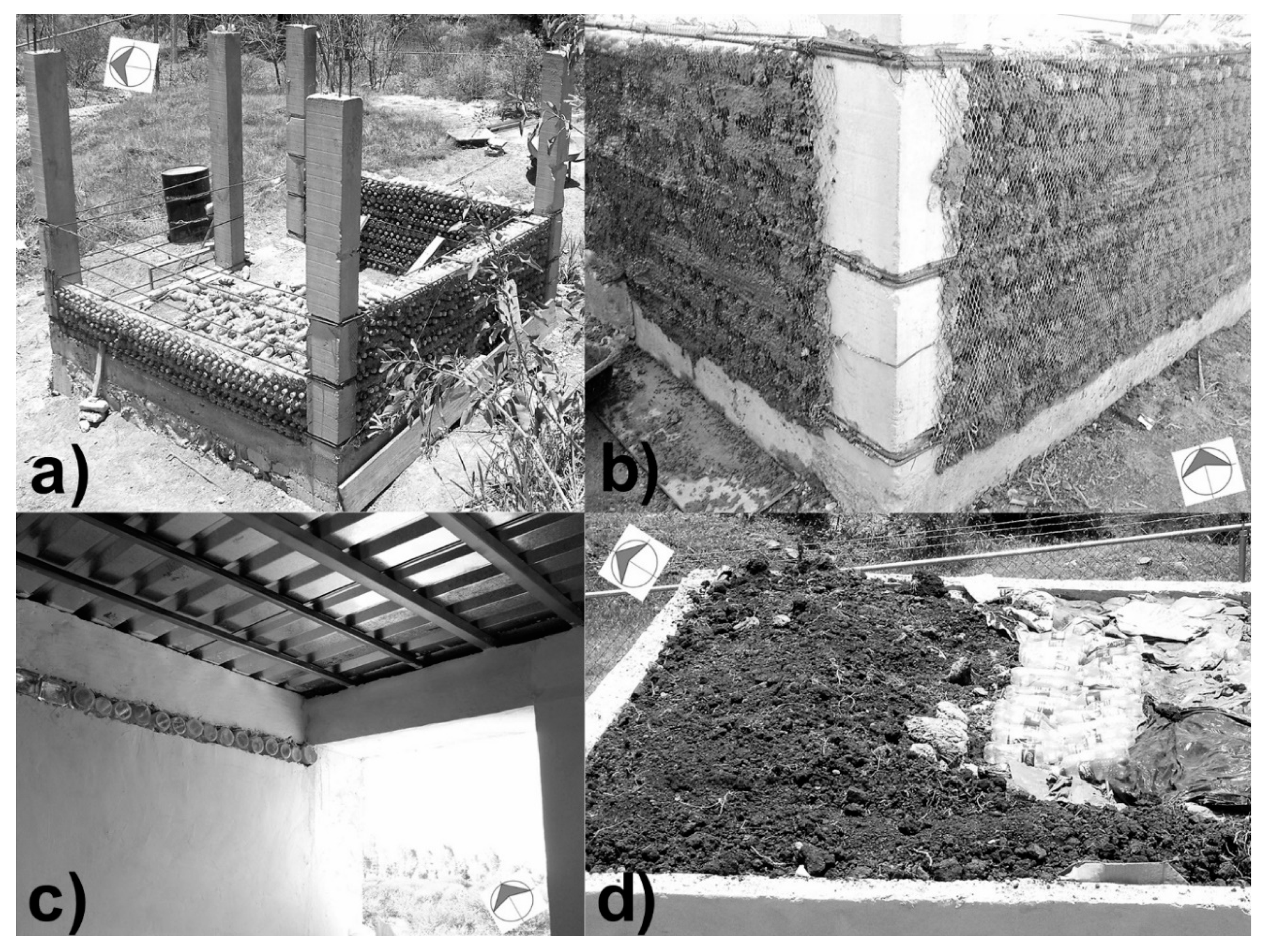
Figure 1. (a) Initial construction stages of a polyethylene terephthalate (PET) bottles prototype room, (b) stacking of PET bottles forming the wall base that was reinforced with steel rebars that were spaced one-half meter apart. (c) Internal view and (d) insulating multiple layers of the roof.
Recycling 05 00002 g001
Figure 2. Annual graphs recorded for a reference site and the PET bottle prototype corresponding to (a) temperature and (b) humidity. The background gray area corresponds to the reference, and the dark area corresponds to the prototype.
Recycling 05 00002 g002
Figure 3. Photographs and thermograms of the PET prototype in different views: (a) photography and (b) thermogram, northeastern (facade) and southeastern side view; (c) photography and (d) thermogram, northwestern and southwestern side view. The thermal images show their scale at the right, the temperature profiles in horizontal and vertical lines, and a histogram of the temperature distribution of the image at the bottom.
Recycling 05 00002 g003
Figure 4. (a) Air temperature that was measured inside the prototype. (b) Temperature data from a sensor inside the multi-layered roof that was located in the double layer of empty opened PET bottles. (c) Air temperature from a reference sensor.
Recycling 05 00002 g004
Figure 5. Photographs and thermograms of the PET prototype in different top views: (a) photography and (b) thermal image, northwestern and southwestern side view; (c) photography and (d) thermal image, southwestern (rear) view.
Recycling 05 00002 g005
Figure 6. The images of thermal transference simulation of the PET prototype. Thermal distribution in (a) outer view and (b) inner view, with bar scale at right. Polygonal net at (c) outer view and (d) inner view.
Recycling 05 00002 g006
Table 1. Parameters used in the simulation of thermal transference. A) Special conditions for sub-domain and boundary conditions. B) Structure boundary conditions.
A) Thermal Parameters of SubdomainsInternal Air EnvironmentFoundationsWallsDoorGreen RoofWindowsGlass Skylights and Ventilation
Thermal conductivity,
k (W/m K)
0.02320.220.371.380.871.381.09
Density, ρ (kg/m3)1.29270035002203210022032203
Heat Capacity,
cp (J/Kg K)
1000385320703920703703
Temperature,
T (°C)
25252047574757
B) Thermal Boundary Conditions
Emissivity, ϵ0.600.900.830.970.780.970.97
Temperature,
T (°C)
25205245624552
Table 2. Parameters of Gaussian fittings for each temperature graph in Figure 1a. Prototype maximum temperature (P-Tmax (1)) and minimum temperature (P-Tmin (2)). Reference maximum temperature (R-Tmax (3)) and minimum temperature (R-Tmin (4)).
1234
P-TmaxP-TminR-TminR-Tmin
y07.035.4317.17−25.02
xc186.74186.69179.59183.22
w246.14241.34220.64515.07
A6076.75862.93528.128714.3
Area7743.87028.19367.15799.4
Center (day)182.8183.0180.3181.6
Height (°C)26.724.829.919.4