1. Introduction
With an energy density that betters that of other energy sources, nuclear energy is currently a major pillar in meeting the energy demands of national societies. When operational, nuclear energy emits no greenhouse gases (GHGs), unlike fossil fuels [
1]. To maintain grid stability, nuclear power plants must operate continuously and provide a reliable primary supply of electricity [
2]. By diversifying energy sources, nuclear energy enhances energy security for many nations [
3]. By reducing reliance on energy imports, atomic energy can help countries with limited access to renewable resources or fossil fuels achieve greater energy independence [
4]. The long-term sustainability of nuclear energy is feasible due to ongoing advancements in reactor technology, including thorium reactors and small modular reactors (SMRs) [
5]. Over the last few decades, atomic energy technology has progressed significantly. Generation IV reactors and other new reactor types are designed to be safer, more efficient, and capable of utilizing a broader range of nuclear fuels, such as thorium and spent fuel [
6]. These advancements may render nuclear energy a more viable long-term solution to the world’s energy challenges. Due to rapid economic development in recent years, electricity consumption is also on the rise. At present, renewable energy sources such as hydropower, wind power, and photovoltaics are constrained by natural conditions and resource utilization, making them difficult to scale as alternatives to fossil energy sources. Therefore, nuclear energy serves as an economical, safe, and reliable source of power generation, offering clear advantages over other forms of energy in all aspects [
7]. Canada operates 19 active nuclear reactors across 4 atomic power stations. In 2017, nuclear energy contributed roughly 15% of the country’s electricity generation. Hydropower remains the dominant electricity source, accounting for approximately 60% of Canada’s electricity in the same year. Although coal was phased out in Ontario by 2014, it is still widely used in other provinces. Non-hydro renewable sources made up about 7% of Canada’s electricity generation in 2017. The mix of electricity sources varies greatly across provinces. For instance, nuclear power provided around 58% of Ontario’s electricity and 36% of New Brunswick’s electricity in 2017. Hydropower is the primary electricity source in British Columbia, Manitoba, Quebec, Newfoundland, and Yukon. In contrast, fossil fuels continue to supply most of the electricity in Alberta, Saskatchewan, Nova Scotia, Nunavut, and the Northwest Territories. Prince Edward Island relies almost entirely on wind power for its electricity generation, with 98% sourced from wind farms, though it still imports around 60% of its power from New Brunswick. Bruce Nuclear Generating Station (NGS), located along the shore of Lake Huron about 190 km from downtown Toronto, Ontario, is the world’s largest operational nuclear facility. It began supplying power to the grid in 1976 and, with eight reactors generating 6288 MWe, produced 48.4 billion kWh of electricity in 2018, enough to power five million Ontario households (each consuming approximately 9600 kWh annually) [
8,
9].
China’s nuclear power sector continues to perform efficiently on a global scale. As of the end of 2021, the country operated 53 nuclear reactors, 18 civil research reactors (considered key facilities), 19 nuclear fuel cycle plants, and 3 designated sites for low-level solid waste disposal, all adhering to high safety standards [
10]. Additionally, 18 nuclear reactors and 1 research facility were under construction, with construction quality generally well-managed. Around 156,000 radioactive sources and 229,000 radiation-emitting devices are being monitored, with no radiation-related incidents reported. While the development of nuclear power is advancing steadily in China, the generation of radioactive waste, primarily solid, remains an unavoidable outcome of plant operations [
11].
According to the government of Canada, the end-2019 waste inventory of high-level waste (HLW), intermediate-level waste (ILW), low-level waste (LLW), uranium mill tailings, and uranium waste rock was 12,718 m
3, 15,681 m
3, 2,524,670 m
3, 218 million tonnes, and 167 million tonnes, respectively [
12]. In 2019, 365 m
3, 182 m
3, 8951 m
3, and 0.75 million tonnes of HLW, ILW, LLW, and uranium mill tailings were generated [
12], while waste inventory projected to 2100 of HLW, ILW, and LLW will be 22,856 m
3, 32,324 m
3, and 3,410,478 m
3, respectively [
12].
According to the International Atomic Energy Agency (IAEA) [
13], the world’s radioactive waste stockpile comprises approximately 180,000 tonnes of heavy metals (tHM) from spent nuclear fuel (SNF), which are primarily stored in temporary facilities, along with about 830,000 m
3 of high-level waste (HLW) from reprocessing and other nuclear processes. Low-level waste (LLW) represents the largest portion of global radioactive waste, with low- and intermediate-level waste (LILW) volume surpassing 7.3 million m
3 [
13]. Moreover, the global radioactive waste burden has grown significantly due to approximately 1.8 billion m
3 of waste generated from uranium mining and milling activities [
13].
Beyond the technical requirements of treating nuclear waste, a sustainable nuclear energy system must address fundamental environmental, social, and ethical concerns. If appropriate safety management procedures are not followed, radioactive waste will continue to pose a threat to ecosystems, groundwater, and soil for tens of thousands of years [
14]. Although deep geological repositories represent a significant advancement in waste management, issues with long-term monitoring, environmental stability, and multigenerational accountability remain [
15]. Safety, public participation, and openness are emphasized as essential components of waste management policy in Canadian legal frameworks [
16]. According to scholarly research, establishing public trust, guaranteeing equitable processes, and upholding environmental accountability are essential for effective nuclear waste governance [
16]. Real sustainability in the disposal of nuclear waste necessitates both technological advancements and comprehensive approaches that tackle environmental and socioeconomic issues.
To effectively meet the needs of the nuclear sector, the management of radioactive waste must continuously evolve. Currently, the primary treatment methods employed by nuclear plants include incineration, cementation, and vitrification. Organic LLW waste goes to incineration for volume reduction, and this process generates off-gases that are treated to be saved before being released into the atmosphere. The solid residue, which is the second byproduct generated from this process, goes to vitrification or cementation, as it is a radioactive byproduct. HLW and ILW typically undergo the intermediate stage before storage, such as vitrification, cementation, or compression. While these methods address some of the waste treatment requirements, challenges such as limited capacity for waste reduction, the potential for secondary pollution, poor cost efficiency, and long processing times must be acknowledged. In particular, the issue of secondary waste contamination remains concerning, as certain radioactive nuclides may not be effectively removed [
7].
Plasma melting technology is an innovative and promising approach that utilizes a conventional plasma torch, or an electric arc generated by one or more graphite electrodes, to oxidize the organic components of radioactive waste while melting the inert components. Non-transferred direct current (DC) torches are predominantly used in this technology. The thermal plasma treatment of waste typically occurs through pyrolysis, gasification, vitrification, and other processes [
17]. For solid wastes with a high organic content, pyrolysis combined with vitrification, or a mix of gasification and vitrification, is usually employed [
18,
19]. Compared to incineration, joule heating, and other methods, thermal plasma technology offers significant advantages [
20,
21]. Refractory wastes with high melting points also boast benefits such as high capacity, a small footprint, and rapid processing speed [
22,
23]. Regarding the use of plasma in treating radioactive waste, according to global research, many liquid and solid wastes can be efficiently treated using plasma melting technology, including those with varying levels of radioactivity, such as plastics, paper, waste resins, oils, and concentrates. This technology is also suitable for non-combustible waste [
8]. Unlike other thermal treatment technologies, this technology is simple and requires no prior preparation. Entire waste drums can be fed into the system without prior material separation [
8]. Thanks to the high temperatures, high enthalpy, and high activity of thermal plasma, which effectively decomposes radioactive waste into gas and dissolved products, this method achieves superior treatment results. The end products are simple: gas and dissolved material [
24]. The dissolved material can be safely stored or disposed of for long periods, and the gas can be cleaned and discharged as needed. Furthermore, as demonstrated by nuclear power plants worldwide, plasma melting technology achieves significant volume reduction [
25]. Inductively coupled thermal plasma, or ICTP, is created when thermal plasma is produced not only between electrodes but also by inductive coupling in certain situations [
26,
27]. In this setup, plasma is generated inside a cylindrical dielectric tube surrounded by an induction coil. Electromagnetic fields produced by radiofrequency (RF) current passing through the coil accelerate electrons inside the torch, resulting in plasma. The plasma assumes a thermal state when operating at high pressures, typically near atmospheric levels, with gas temperatures rising to several thousand Kelvin, which is very close to the electron temperatures.
Compared to DC and microwave (MW) torches, RF-ICP torches offer several advantages: they easily ignite plasma at atmospheric pressure, whereas DC and microwave torches (MW) require complex ignition circuits [
28,
29]. At lower power, RF-ICP torches produce high-density plasma and do not require the advanced cooling systems of DC torches, as electrode cooling is essential for plasma stability [
26]. The capacity of ICTP to provide a pristine, high-temperature environment devoid of electrode material contamination is one of its main advantages. Utilizing these benefits, ICTP torches have been used for a variety of purposes, such as disposing of garbage [
26,
30]. By taking advantage of these benefits, ICTPs have been used in a variety of fields, such as waste disposal [
21], the creation of thermal barrier coatings [
31], and the physical vapour deposition method known as plasma spray [
32]. Even while ICTP torches have been successfully used in several material processes, some drawbacks have also surfaced. These include issues with counterflows in the circulating gas, decreased power efficiency (40–70%), steady operation in the face of disruptions, and managing gas temperatures [
21].
The objective of this study is to design and develop an RF-ICP torch for laboratory-scale treatment of incinerable LLW and ILW waste using plasma technology. The primary goal is to achieve maximum waste volume reduction, which requires a highly efficient power plasma torch, a high-temperature plasma jet, and high plasma heat flux. We are using COMSOL Multiphysics v6.2 (AC/DC module, CFD module, Plasma module, Design module) to design and optimize the RF-ICP torch.
2. Results and Discussion
One of the most important benefits of RF-ICP discharge in various applications is its ability to produce high-density plasma compared to other plasma sources [
21]. Many parameters affect the performance of a plasma torch, thus impacting its applications. In materials processing applications, such as waste pyrolysis, plasma density and temperature are key factors in determining plasma characteristics [
7,
33,
34]. Plasma density, or charge density, is responsible for transferring energy from the electrical source to the material. Meanwhile, the electron temperature is responsible for increasing the reactor temperature to initiate material decomposition [
35,
36]. For a torch to be effective in material property applications, it must maintain both high plasma temperature and high density. Gas flow pattern influences the plasma parameter and the plasma temperature [
27]. Vortex flow has been proven to be the most effective gas flow pattern on plasma parameters [
26]. Since only electrons are able to follow the rapidly changing electric field, they are principally responsible for driving the excitation and ionization processes that take place in the RF-ICP discharge. On the other hand, because of their restricted mobility, ions in the RF discharge have little influence and do not substantially contribute to the RF plasma discharge [
37]. The most dominant scenarios of losing electrons inside the plasma discharge and its energy are hitting the wall of the reactor or colliding with neutrals to generate excited atoms or molecules. Vortex flow helps minimize the loss of the energy of electrons by separating the plasma from the wall with the cooled gas barrier [
38].
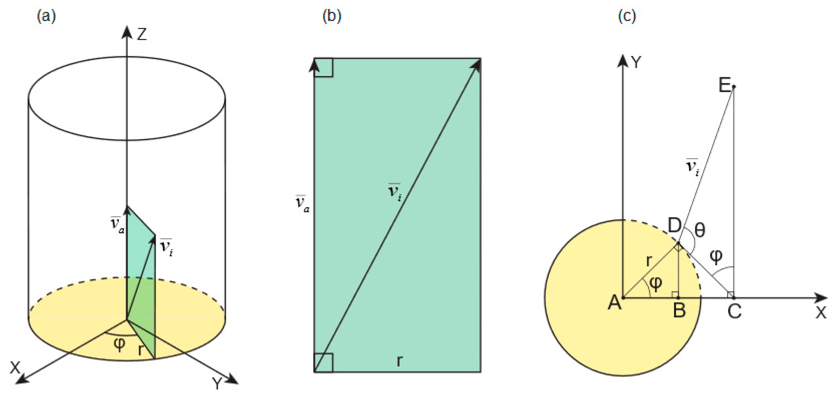
In the case of vortex flow, two velocities control the gas motion inside the torch body: axial velocity and tangential velocity. The higher the tangential velocity, the greater the separation between the plasma and the chamber wall [
39]. This increase enhances the centrifugal force, which confines the hot plasma core and pushes cooler plasma-forming gas toward the wall. Tangential velocity
is a function of the radial distance
and the angular velocity
, and is given as the following:
where
is the radial distance from the axis of symmetry, and
is the angular velocity [
40,
41]. The angular velocity is greatly affected by the inlet angle (
φ); a steeper angle towards the tangential direction increases the vortex [
40,
42].
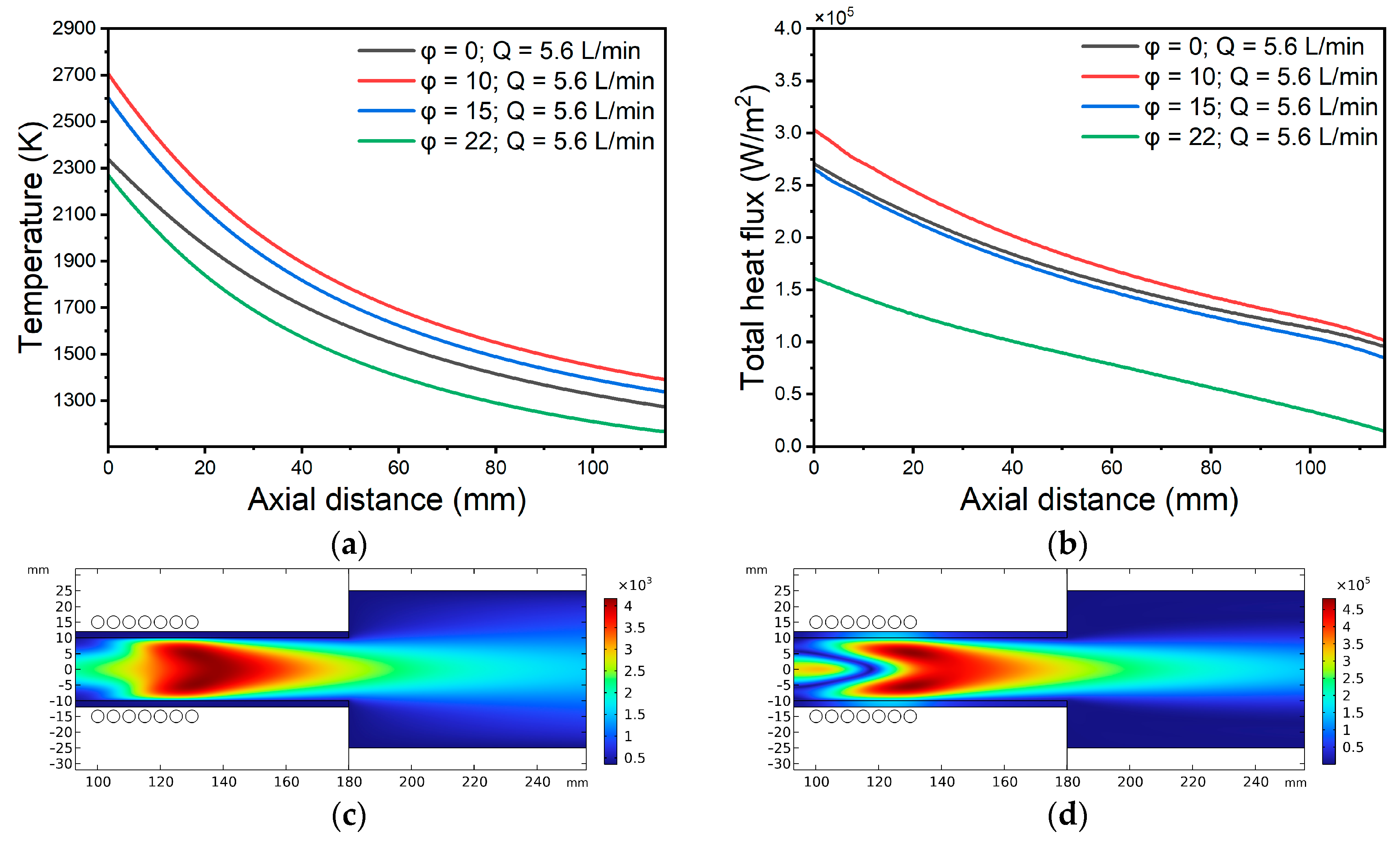
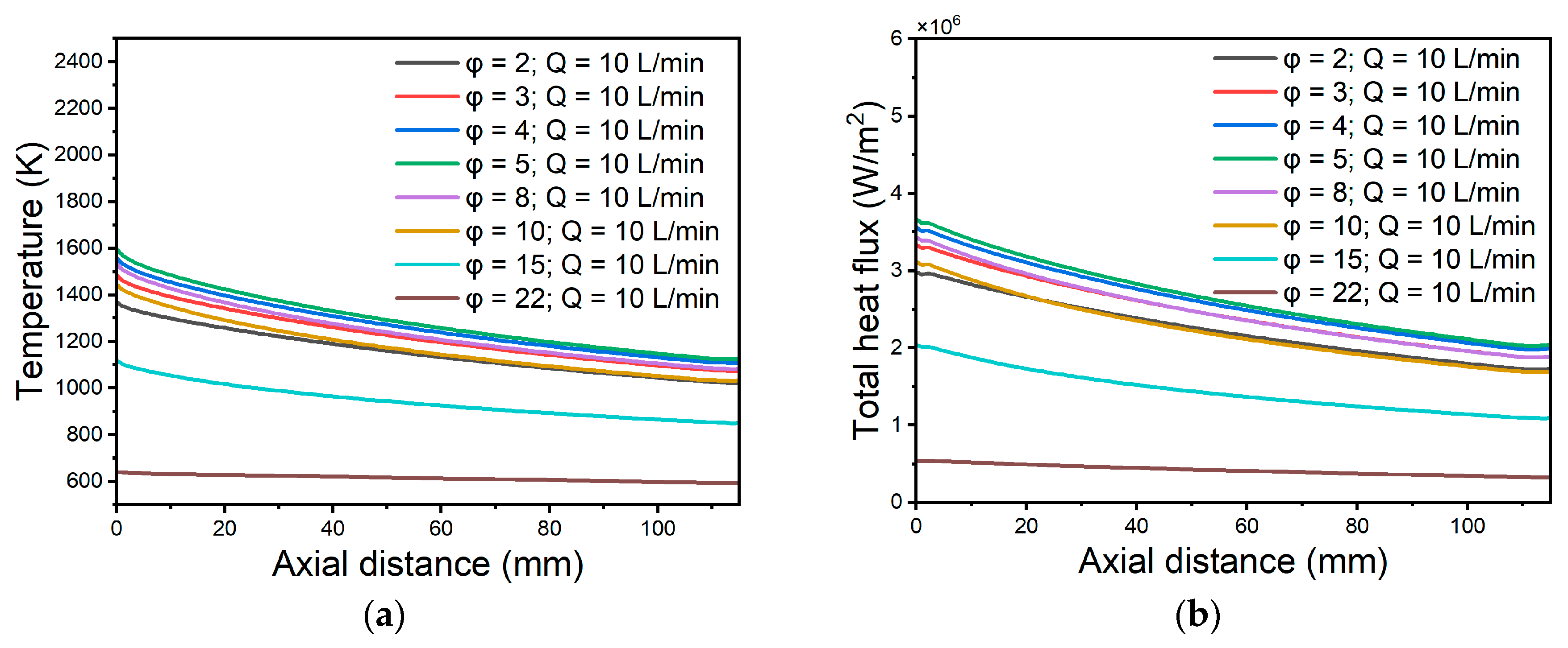
Figure 1a,b illustrate how the plasma temperature and heat flux outside the torch vary under a 5 SLPM Ar flow for different
φ angles, while
Figure 1c,d present the plasma temperature and total heat flux at
φ = 10°, respectively. The heat flux is a function of the plasma density [
43]. At
φ = 0°, the flow pattern is direct, and as
φ increases, the gas begins to circulate in the plasma chamber, further confining the plasma. For both temperature and heat flux, the best result was achieved at
φ = 10°. Equation (2) can be used to calculate the angle of the gas inlet tube into the torch body, where we can use
φ:
where
r is the radial distance from the axis of symmetry,
is axial velocity [see
Appendix A for the equation derivation details]. In the equation, we use the optimal
φ value to determine the position of the gas inlet tube that gives the maximum vortex flow pattern, which leads to the maximum centrifugal force that confines the plasma.
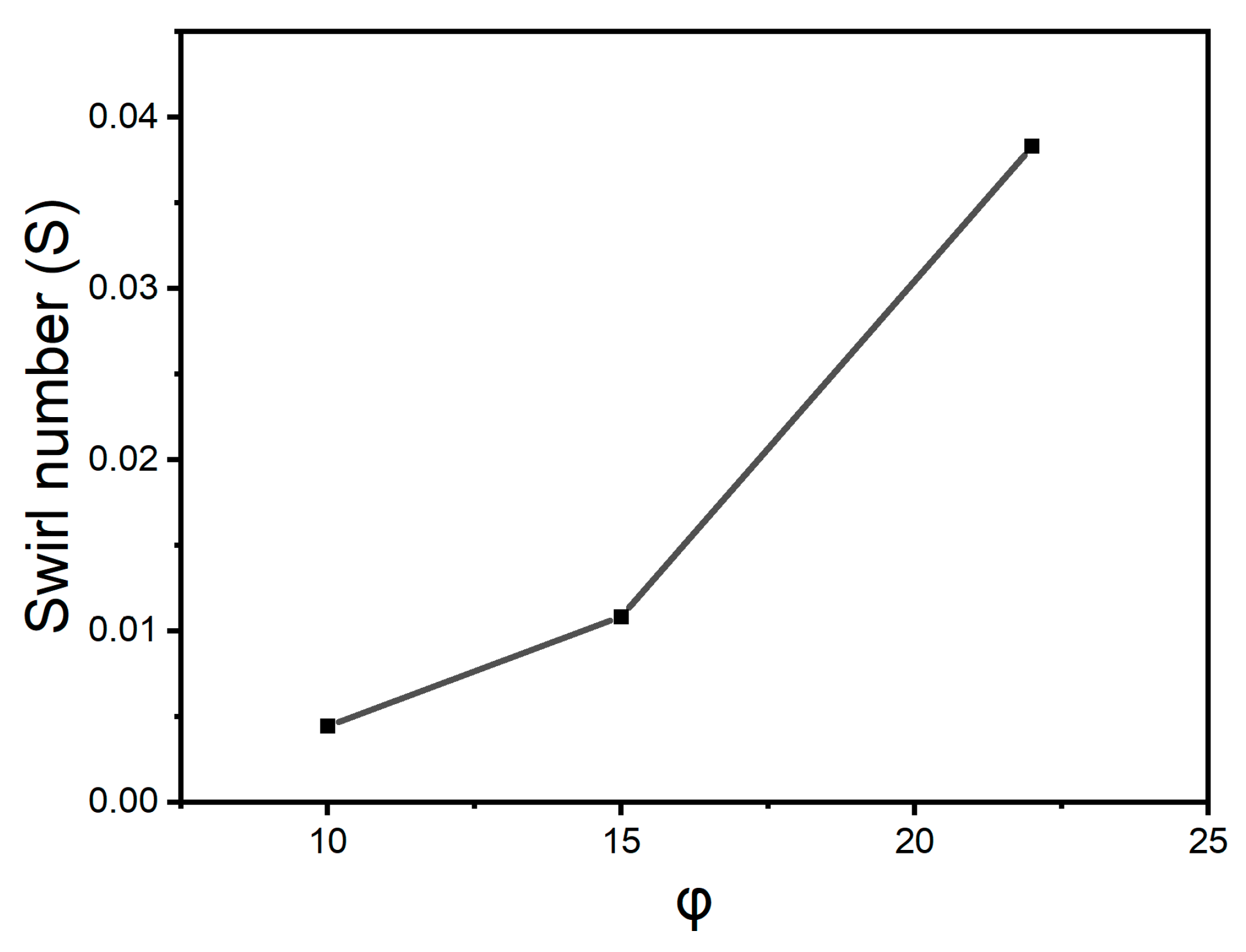
As
φ increases beyond 10°, the number of gas rotations increases. The swirl number is commonly used to describe the degree of swirl in a swirling flow. It was first introduced by Beer, while Shen et al. simplified it as follows [
44,
45]:
where
is the axial flux of the tangential momentum,
is the axial flux of the axial momentum,
R is the outer radius of the ring,
is the tangential velocity,
is the axial velocity at corresponding radial position
r.
Assume that the tangential and axial velocity patterns are consistent across the flow radius. This implies that the velocities remain constant when moving radially outward. This simplification is commonly used in cases involving ideal flows or very small vortices.
So, Equation (1) can be simplified to:
where
R is the torch radius.
By calculating both velocities at the center of the coil region, using Equation (4) to calculate the variation of the swirl number with different values of
φ, and plotting the results in
Figure 2, we observe that the swirl number increases with
φ. This increases the probability of electron–electron collision, elastic electron–atomic collision, and electron–wall collision. All of these processes can affect the properties of plasma.
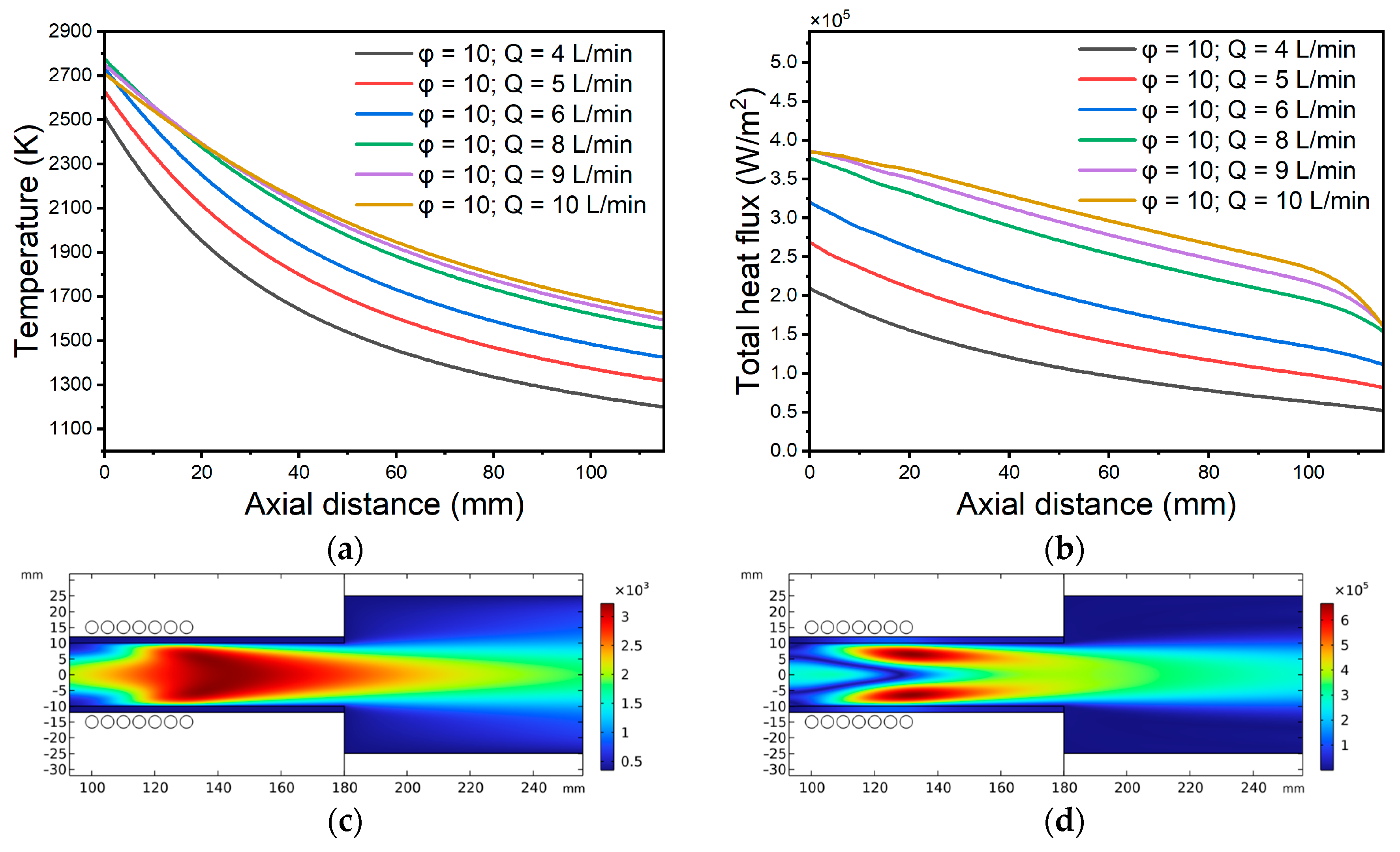
It is commonly known that electron temperature, radiofrequency power, and gas flow rate are related. Because of the increased impact of the two-stage ionization process and electron–electron interactions, which intensify at increasing plasma densities, the electron temperature generally falls as RF power rises. As the gas flow rate rises, the electron temperature likewise falls concurrently. More gas atoms are produced by the increased gas flow rate, which raises the likelihood of electron–atom collisions, raising plasma density and lowering electron temperature [
27].
Figure 3a,b illustrate how plasma temperature and total heat flux vary with distance from the torch for different Ar flow rates at
φ = 10°, while
Figure 3c,d show those same parameters at the optimal flow rate of 10 SLPM with
φ = 10°. Increasing the Ar flow rate from 4 to 10 SLPM raises both plasma temperature and heat flux, while further increasing the flow rate causes both to decrease. This reduction in plasma properties with flow rate can be explained by the fact that the plasma volume increases and begins to contact the wall, despite the rotational motion that confines the plasma. In this case, the size and geometry of the plasma chamber must be considered. The torch body geometry and design should be modified to enhance the centrifugal force generated by the vortex flow and, thus, improve the plasma parameters.
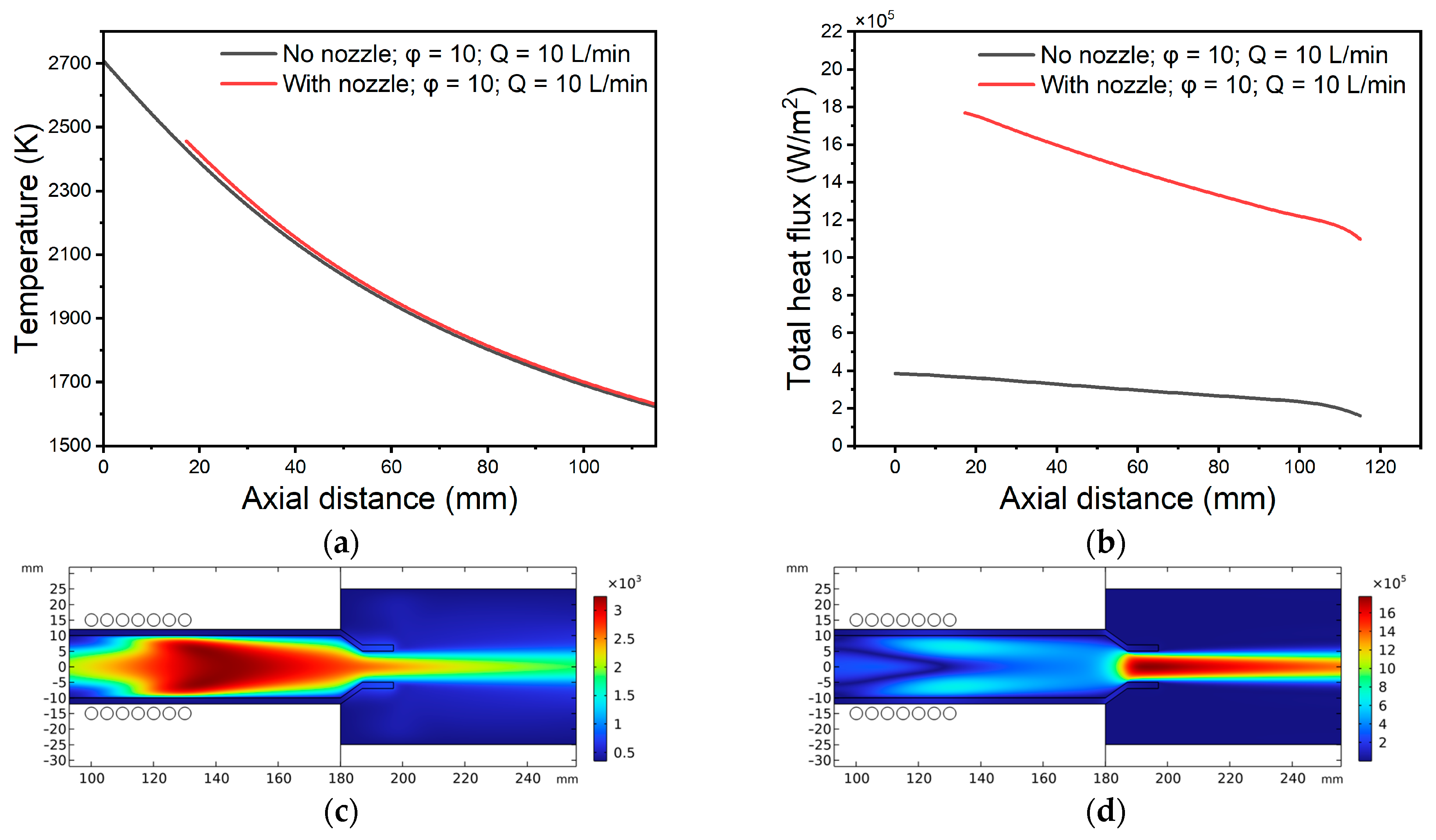
Figure 4a,b illustrate how fitting a 1 cm long, 5 mm radius nozzle onto the plasma chamber outlet alters the spatial profiles of plasma temperature and total heat flux at an Ar flow of 10 SLPM and
φ = 10°.
Figure 4c,d then show those same plasma parameters when the nozzle is installed. The plasma temperature did not change after adding the nozzle to the end of the torch, while the heat flux increased from
.
Figure 5a,b show how the plasma parameters vary with distance from the torch outlet for several nozzle radii, using a fixed length of 1 cm, a flow rate of 10 SLPM, and an angle
φ of 10°.
Figure 5c,d then illustrate these same plasma parameter profiles at the optimal nozzle radius of 3 mm. The electron temperature increases by increasing the diameter increases, while the heat flux has the opposite behavior.
Adding a nozzle to the plasma chamber stabilizes the vortex’s position and size, helping to maintain a constant flow. It also prevents the internal spiral from collapsing near the apex, which could destabilize the vortex flow. The apex diameter (downflow) has a significant impact on overall performance. Increasing it reduces the pressure drop and turbulence intensity, which affects the plasma’s total heat flux by reducing it and increasing the plasma temperatures, as the collision rate of electrons with neutral atoms decreases. After adding a nozzle, the gas inlet angle should be re-examined, as the nozzle alters the velocity profile inside the torch.
Figure 6 displays the changes in plasma temperature and the total heat flux with
at 3 mm nozzle radius and 10 SLPM gas flow rate, torch body radius 10 mm, and RF power 770 W. The gas inlet angle is optimal at 5°.
The diameter of the chamber significantly impacts the energy distribution within an RF-ICP system. A larger chamber diameter typically enables a more uniform plasma temperature by diminishing the effects of wall cooling, a major source of energy loss. In smaller chambers, plasma species are more likely to interact with the chamber walls, resulting in increased thermal losses and lower plasma temperatures. The studies indicate that the plasma temperature in RF-ICP systems is influenced by power coupling efficiency and energy losses [
46]. In larger chambers, reduced wall interaction helps maintain higher electron temperatures, thereby improving ionization efficiency. Conversely, in small chambers, more wall interactions result in heat loss and a decrease in electron density, ultimately lowering the overall plasma temperature. Heat flux in RF-ICP discharges is mainly governed by convection, radiation, and conduction. The chamber diameter affects the distribution of heat flux density on the chamber walls. A small-diameter chamber leads to higher localized heat flux due to increased plasma–wall interactions, creating steeper thermal gradients and potential damage to chamber materials. Research has shown that larger chamber diameters distribute heat flux more evenly, preventing excessive thermal stress on specific areas [
32,
47]. Furthermore, larger chambers facilitate better heat dissipation, reducing localized overheating and enhancing discharge stability. The chamber size also affects plasma stability. Larger diameters help reduce turbulence and enhance plasma confinement, providing sufficient space for ionization and recombination processes to occur without significant energy loss. In contrast, small-diameter chambers can result in plasma instabilities due to increased wall interactions and concentrated heat flux, potentially leading to non-uniform plasma distributions.
Figure 7a,b show how the plasma parameters vary with distance from the torch outlet for several plasma chamber diameters, using a nozzle radius of 3 mm, a flow rate of 10 SLPM, and an angle
φ of 5°. By increasing the diameter of the plasma chamber from 10 to 16 mm, the temperature and heat flux increase. Rising to 18 mm causes a reduction in both parameters.
Operationally, the RF-ICP torch is non-propagating. In order to exhibit the skin effect, the driving RF field penetrates the plasma in a skin layer (δ) close to the antenna [
47,
48]. The induced electric current and radio frequency field are focused on the plasma’s surface. Since electrons are more mobile than ions, only electrons are in charge of ionization and energy transmission. The electric field in the skin layer gives the electrons energy, which they then pass to the gas atoms to produce more charges and raise the material’s energy conversion rate. During the treatment process, the torch’s efficiency is reduced as the charge density is decreased. Either producing solely excited atoms or allowing energetic electrons to diffuse to the reactor walls might result in the loss of charges. A solution has been created to produce a high axial flow of Ar gas, generating a cooled barrier gas that isolates the plasma from the walls in order to reduce electron loss through the chamber wall. Initiating a vortex flow, which is comparable to high axial flow, is the second solution [
38]. Another energy loss mechanism was detected due to the anomalous skin effect. Most electrons with sufficient energy did not contribute to the ionization of the atoms, which would increase the current density. Consequently, the charge density decreases, along with the energy efficiency of the torch. Anomalous skin effect is an uncontrollable phenomenon that can only be detected and attempted to be avoided. Plasma stability and homogeneity, effective electromagnetic coupling, enhanced energy absorption, and improved gas dynamics all depend on the chamber diameter in radiofrequency discharges. Instability, reduced efficiency, or substandard plasma performance can result from diameter mismatch. RF power was simulated to study its effect on the plasma parameters.
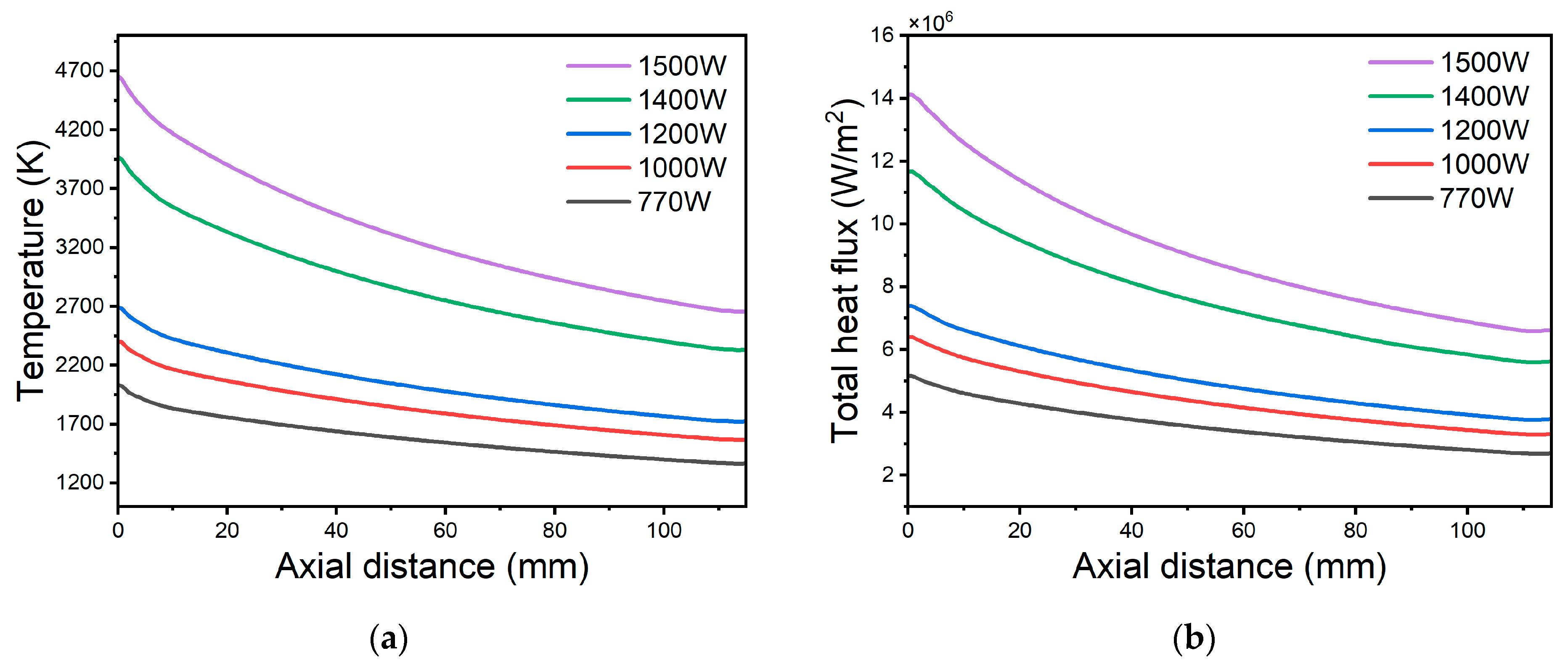
Figure 8a,b display the impact of the RF power on the plasma temperature and the plasma heat flux along with the distance from the nozzle at an Ar gas flow rate of 10 SLPM, nozzle radius of 3 mm, torch body diameter of 16 mm, and
φ equal to 5°. Power increases the energy of the electrons, and as a consequence of this, the plasma density increases.
Table 1 summarizes the specifications of the RF-ICP torch components for the various gases: argon (Ar), nitrogen (N
2), and oxygen (O
2). In waste treatment, plasma, argon, and nitrogen are used in the pyrolysis process, as pyrolysis is a thermal decomposition process that occurs in the absence of O
2 and is carried out in an inert gas atmosphere [
21]. Oxygen is considered in simulation because, with high RF power, the torch can be used for gasification, a process that requires the presence of O
2 and temperatures above 800 °C [
49]. During the O
2 and N
2 simulations, only the nozzle diameter was changed, as the goal is to use the same torch simulated for the pyrolysis process to ignite the plasma with the other gases. Therefore, from an economic point of view, the torch body and gas inlet angle will not change; only the interchangeable nozzle can be replaced. Power efficiency can be calculated using the following equation:
where
η is the torch power efficiency ratio (%),
is the generated thermal power from the plasma, and
is the electrical power input.
In
Table 1, the energy efficiency was calculated from the surface integration of the heat flux at 58 mm distance from the torch body/nozzle tip, for two cases: with a torch radius of 10 mm (the starting diameter) (
), a flow rate of 10 SLPM,
φ = 0° (an axial gas flow pattern), and an electrical power of 770 W. The final energy efficiency (
) was then calculated under optimal conditions (3 mm nozzle radius, 10 SLPM gas flow rate, 16 mm torch radius, and
φ = 5°). The energy efficiency of the torches was improved by optimizing their design, reaching approximately 93%. The heat flux of nitrogen and oxygen gases is higher than that of argon. This is because the ionization temperature of these gases is lower than that of argon, leading to increased charge generation.


