Article

Recycling of Poly(Propylene) Based Car Bumpers in the Perspective of Polyolefin Nanoclay Composite Film Production

1
Department of Mechanical Engineering, School of Engineering, Holy Spirit University of Kaslik (USEK), Jounieh P.O. Box 446, Lebanon
2
Department of Polymer and Process Engineering, Novoloop, Menlo Park, CA 94025, USA
3
Department of Chemical and Petroleum Engineering, Holy Spirit University of Kaslik (USEK), Jounieh P.O. Box 446, Lebanon
*
Author to whom correspondence should be addressed.
Recycling 2025, 10(3), 95; https://doi.org/10.3390/recycling10030095 (registering DOI)
Submission received: 4 February 2025 / Revised: 9 April 2025 / Accepted: 17 April 2025 / Published: 10 May 2025
(This article belongs to the Special Issue Challenges and Opportunities in Plastic Waste Management)

Abstract

:
This study uses the melt compounding method to recycle polypropylene-based car bumper waste (PP-CBW) in order to produce nanocomposite films for mulch application. The nanocomposite films were compounded by mixing virgin linear low-density polyethylene (LLDPE) with PP-CBW at a constant ratio of 4:1 in the presence of different percentages of nanofillers. Nanocomposites reinforced with nanoclays were compatibilized with an anhydride grafted polyethylene (PE-g-MAH), at a constant compatibilizer-to-clay ratio equal to 3, to improve the adherence between the nonpolar matrix and the hydrophilic nanoclay and acrylic paint present in the car bumper. An extruder with a corotating twin screw was used to produce blends of different compositions. To create nanocomposite films, the mixtures were further processed in a blown film extruder. The effect of the presence of nanoclays on the barrier, thermal, and mechanical properties of the nanocomposite films was investigated. The dispersion of clay layers in the matrix was examined by atomic force microscopy (AFM). The results indicate that 3 wt% of clay loading maximized the tensile strength in the transverse direction (TD) and machine direction (MD). A 1 wt% clay loading increased the MD tear resistance by 66% and manifested an optimum dart impact strength. Significant improvements in thermal and barrier properties were also achieved in the presence of 3 wt% clay loading.

Graphical Abstract

1. Introduction

One significant market for plastics and polymer composites is the light vehicle sector. The bumper, which is composed of thermoplastic polyolefin elastomers (TPOs), is the most noticeable plastic part of a car. TPOs are multiphase materials that have a nodular shape [1]. The rubber phase is dispersed throughout the polypropylene (PP) matrix as spherical particles. Rear bumpers are frequently manufactured using talc-filled TPOs to save production costs, and front bumpers are built of pure TPOs to benefit from their elasticity [2]. Based on their size and surface treatment, fillers may either become encapsulated within the rubber particles or be dispersed throughout the PP matrix.
Used car bumpers are challenging to market due to two main problems: firstly, older bumpers become less attractive as bumper styles vary annually. The second problem is that the plastic is coated and has talc fillers, which makes recycling more difficult but still achievable [3]. Different technologies are used for the recycling of polypropylene-based materials such as mechanical recycling, chemical recycling, and burning of polymers to recover energy [4,5,6,7,8]. Mechanical recycling is an efficient way to recycle car bumpers and recover their original properties. Numerous articles discuss the recycling of discarded polyolefins to create second-grade pellets that can be used as raw materials in a variety of industries [9,10]. Nevertheless, the equivalent recycled materials’ mechanical qualities differ from those of virgin materials [11,12]. For instance, recycled TPOs may not serve as a direct substitute for virgin TPOs in high-performance applications such as automotive bumpers, however, they demonstrate excellent properties that could make them suitable for use in less demanding applications across other industrial sectors [13].
Due to the diminished properties of recycled polyolefins, plastic recyclates are typically enhanced by incorporating micro or nanofillers to create composite materials [14]. Among various fillers, clays have demonstrated significant advantages. Compared to pure polymers or composites with conventional fillers, polymer/clay nanocomposites exhibit superior characteristics, including improved gas barrier performance, flame resistance, enhanced mechanical properties, and optical clarity. Many authors [15,16] have demonstrated that nanoclay-based nanocomposites’ resistance to water absorption and tensile strength is improved by increasing the nanoclay-to-polymer loading %. Mural et al. [17] have investigated the effect of nanoclay loading on the mechanical characteristics of recycled polypropylene (PP)/high-impact polystyrene blend showing an improvement. However, they found that at a clay loading of 3 wt%, the mechanical properties of the matrix began to deteriorate due to the agglomeration of the nanoclay within the polyolefin-based blends. Clay requires a compatibilizer to be successfully incorporated into the polyolefin matrix. Durmus et al. [18] have reported that low molecular weight oxidized polyolefins could be employed as a novel kind of compatibilizer to create polyolefin/clay nanocomposites through melt processing. Adeknule et al. [19] investigated making car bumpers out of recycled plastic waste polyethylene terephthalate, high-density polyethylene (HDPE), and PP, along with ethylene glycidyl methacrylate copolymer compatibilizer. They demonstrated that the blend’s mechanical qualities were more affected by the presence of the compatibilizer rather than the variation of the plastic types, and the recycled blend showed potential for bumper production. Luda et al. [2] characterized mechanically and morphologically three different blends of PP-based car bumper waste prepared in the presence of compatibilizer, and fillers. They have shown that block copolymer polyethylene–polypropylene compatibilizers enhance the compatibility of the bumper’s rubber domains with the PP matrix resulting in sufficient impact strength results.
The influence of the nanoclay on the crystallization behavior of polyethylene (PE) has been widely studied [20,21,22]. Wang et al. [23] reported that the exfoliation and intercalation behaviors of polyethylene grafted maleic anhydride (PE-g-MAH)/clay nanocomposites prepared via melt compounding were highly dependent on PE-g-MAH content and the organic modifier’s chain length. Similarly, Koo et al. [24] demonstrated that the morphology and anisotropic phase formation of PE-g-MAH/layered silicate nanocomposites were influenced by clay content. Wu et al. [25] observed that dispersed clay layers act as nucleating agents, leading to increased crystallization peak temperature, enhanced polymer crystallization rates, and changes in crystal growth geometry. Exfoliated clay significantly influences polymer chain mobility, restricting chain movement near the clay surface and thereby reducing crystallinity.
One of the promising applications of recycled polyolefin/clay nanocomposites is in plastic mulch films. By improving gas barrier properties, these films can effectively be utilized for fumigation mulch applications. The characteristics that determine a film’s permeability are its oxygen transmission rate (OTR) and water vapor transmission rate (WVTR). The oxygen permeability of low-density polyethylene (LDPE) and LDPE/clay nanocomposites at different clay loadings, including 1, 3, 5, and 7 wt% was studied by Arunvisut et al. [26]. Oxygen permeability dropped by 24% when clay loadings increased from neat PE to 7 wt% of clay. The author demonstrated that to achieve improved gas barrier properties, an exfoliated structure of clay platelets is preferred because it makes gas diffusion through the material more difficult.
The aim of this work is to recycle painted car bumpers in a cost-effective way to produce plastic mulch films. Currently, recycling car bumpers into high-performance film products presents a significant technical challenge. The challenges will be addressed in this work through compatibilization and performance enhancement using nanofillers on one hand and achieving uniform dispersion and optimal interfacial bonding by employing melt intercalation with co-rotating intermeshing twin-screw extrusion on the other. This method’s compatibility with large-scale, solvent-free processing offers an effective approach to producing sustainable, high-performance polymer/clay nanocomposites. Nanocomposite films were prepared by mixing the waste with a certain quantity of compatibilizers, fillers, and virgin linear low-density polyethylene (LLDPE). Nanoclay fillers compatibilized with PE-g-MAH were used to enhance the mechanical and barrier properties of the produced films. During this investigation, properties such as oxygen barrier, mechanical, clay dispersion inside the matrix, and thermal characteristics were carefully examined.

2. Results and Discussion

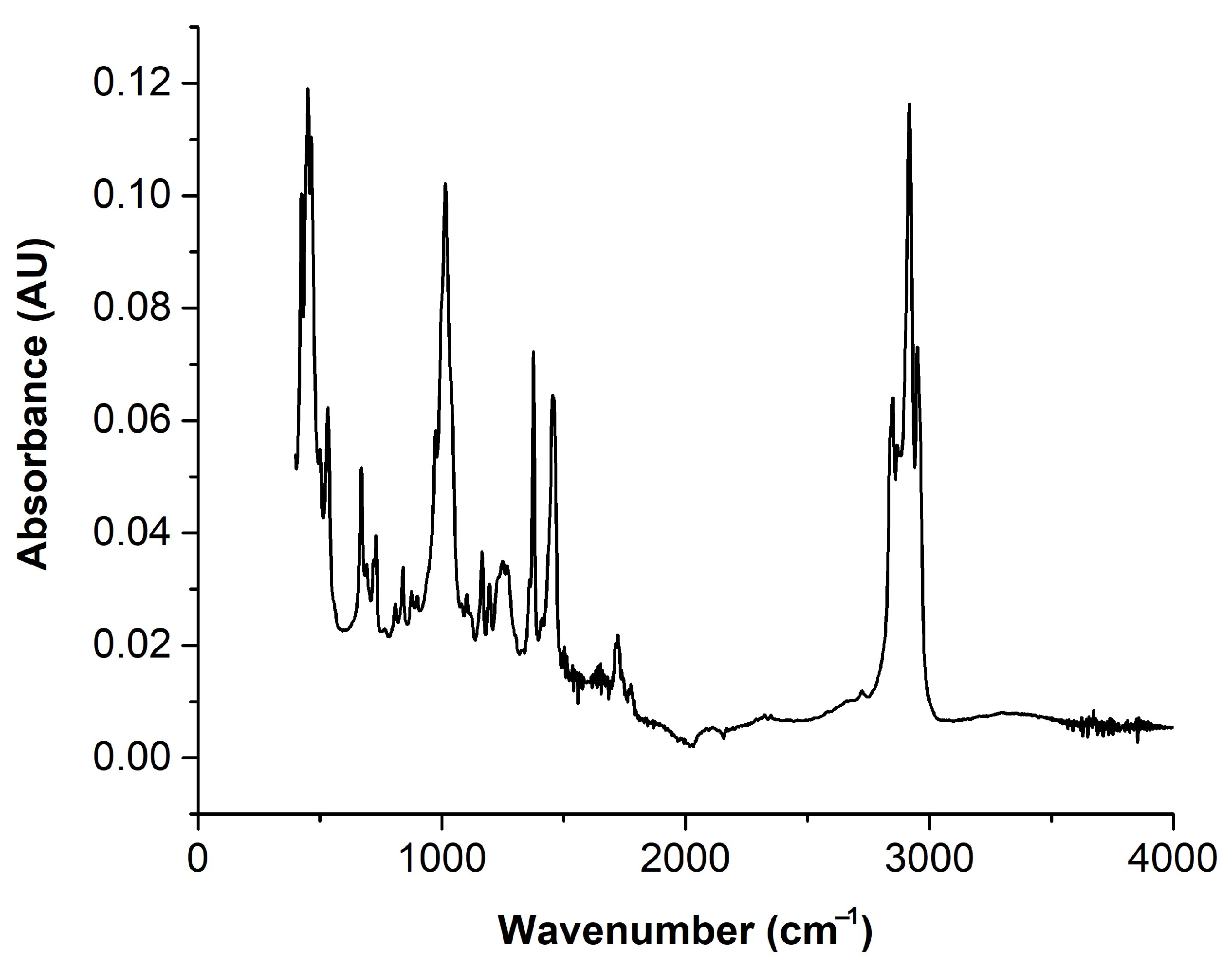
2.1. Car Bumper Composition

FTIR, DSC, and TGA were first used to characterize the composition of the automobile bumper trash. Key components such as PP, a PP-based elastomer, PE, acrylic paint, and talc are identified by the FTIR spectrum, which is displayed in Figure 1. Acrylic paint is indicated by peaks at 1719 and 1776 cm−1, whereas the PP-based elastomer is associated with the absorbance at 1544 cm−1. The PE fraction obtained from both the Vistamaxx PP-based elastomer and the PP block copolymer is represented by the peak at 726 cm−1. The following are characteristic peaks for PP: 1455 cm−1 (CH2 bending); 1377 cm−1 (CH₃ bending); 1166 cm−1 (C-H bending); 840 cm−1 (CH2 rocking and C-CH₃ stretching); and 808 cm−1 (CH2 rocking in the head-tail structure particular to PP crystals) [27]. Additionally, peaks at 1014 cm−1 and 457 cm−1 verify that the bumper material contains talc.
The used bumper’s DSC thermogram (Figure 2) shows two peaks: one at 116 °C, which is linked to the crystallization temperature (Tc) of HDPE, and another at 125 °C, which is indicative of the melting temperature (Tm) of HDPE. Additionally, the bumper material appears to contain a nucleated polypropylene block copolymer, as indicated by a Tm of 164 °C and Tc of 126 °C. The crystallinity percentage of PP in the bumper waste was estimated to be 45%.
TGA analysis was conducted to assess the thermal stability and compositional characteristics of car bumper waste. Figure 3 illustrates that polypropylene shows a Td,onset of 443 °C, and a Tpeak of 468 °C. The residual mass, determined from TGA, represents the inorganic content of the sample. These values allow us to estimate the proportion of the organic phase. The results also show that the bumper material contains 5% CaCO3, 9% inorganic talc residue, and 84% organic polypropylene.

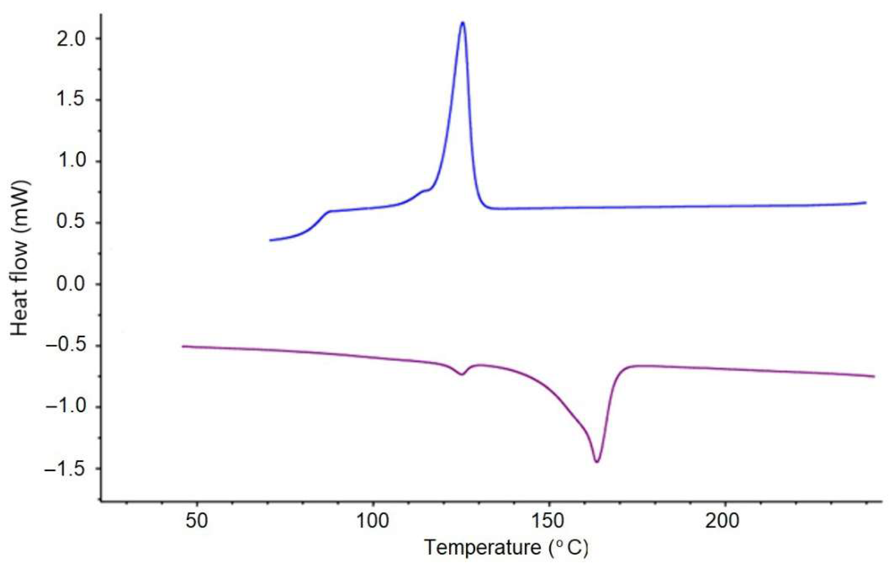
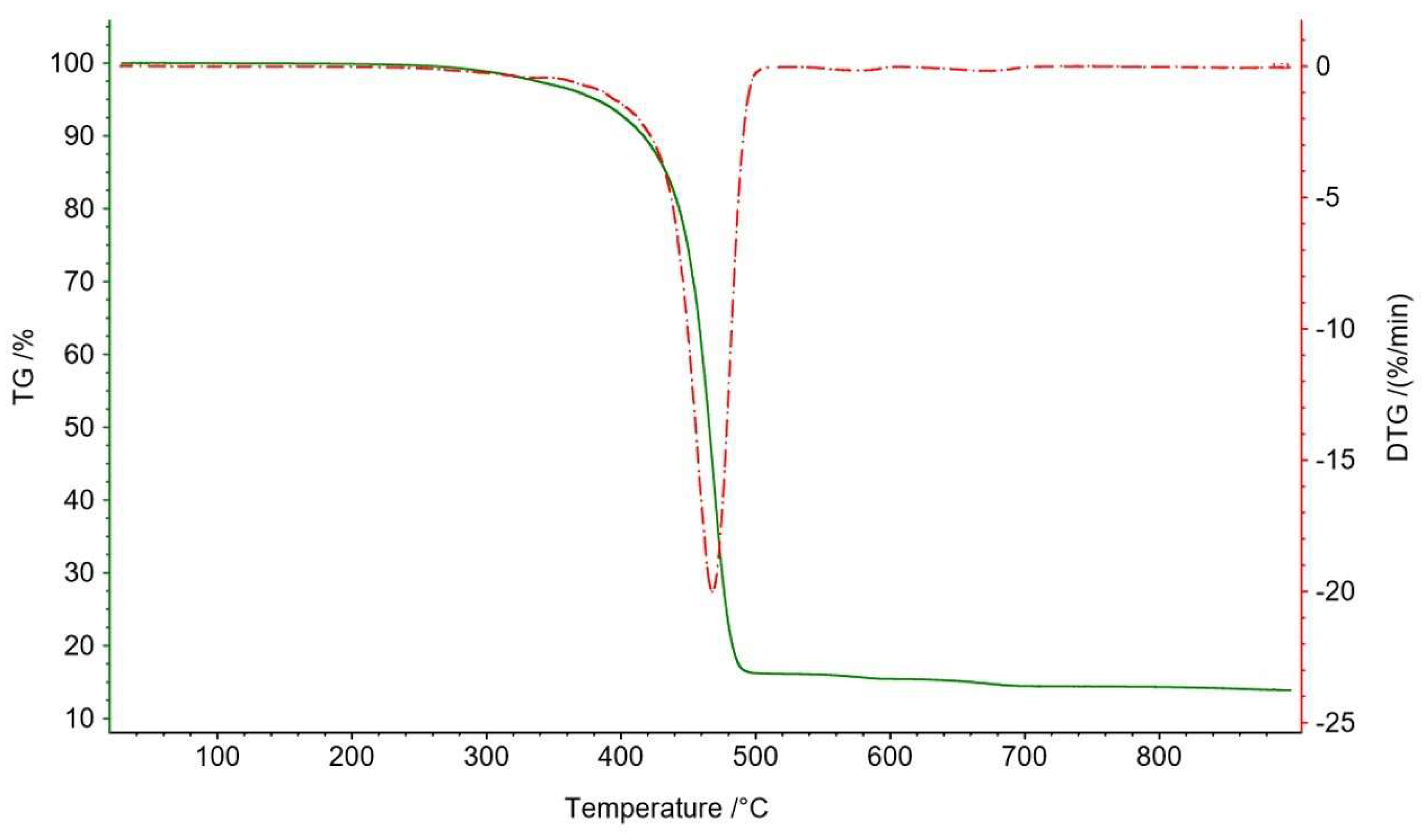
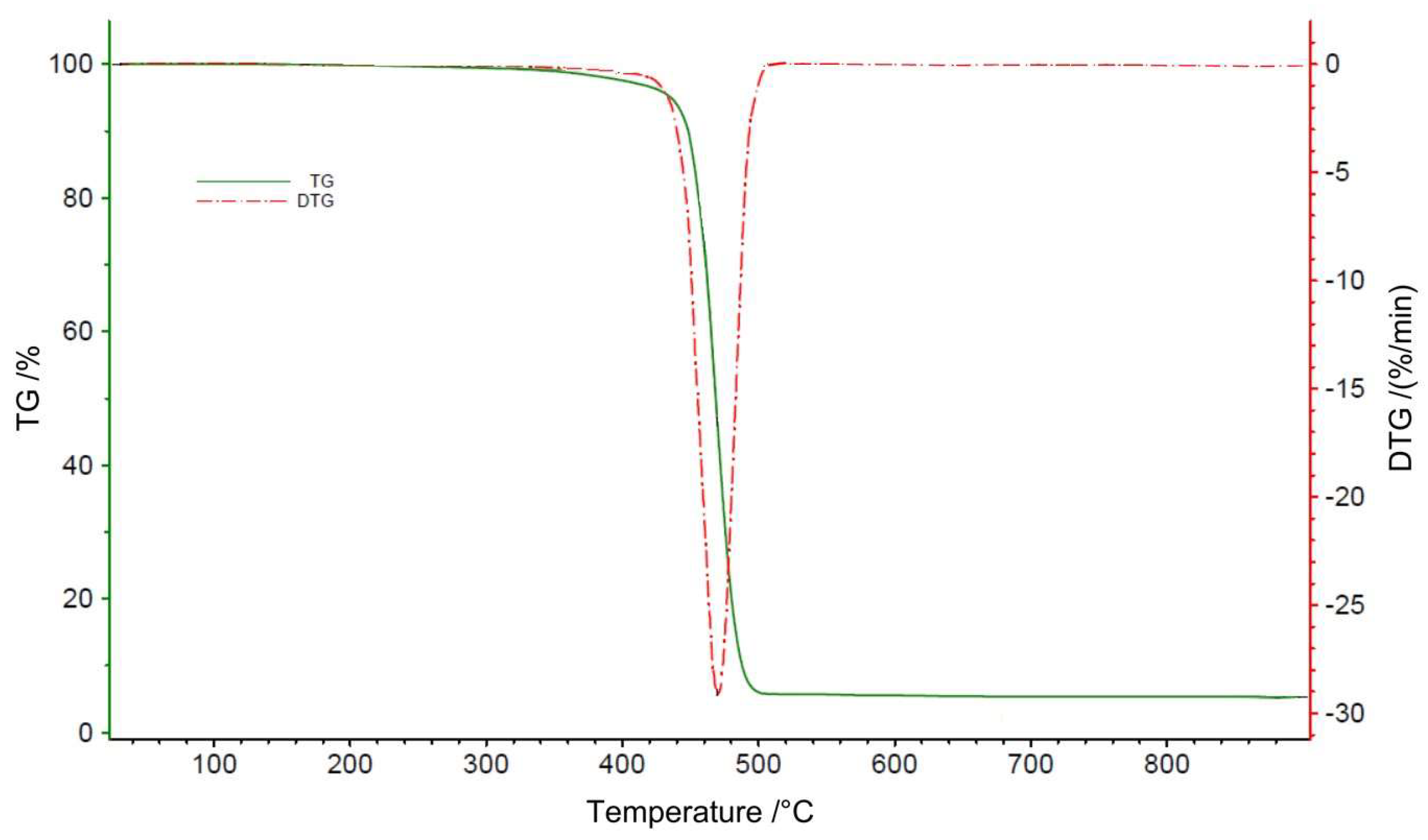
2.2. Thermal Properties of the Nanocomposites

Modifying the crystallization features of the polymer matrix can have a substantial impact on the mechanical properties of the composites. The DSC results for blends F, C, D, and E reinforced with 0, 1, 3, and 5 wt% of nanoclay, respectively, in the presence of PE-g-MAH as a compatibilizer are displayed in Figure 4 and Table 1. As shown in Table 1, the crystallinity in blend F containing no nanoclay is higher than that in blend C containing 1 wt% nanoclay. This is due to the nucleation effect coming from the significantly higher % of MAH in blend F (9% in blend F versus 3% in blend C). The highest % of crystallinity (Xc = 78.6%) is observed in the blend D film, due to the combined nucleation effects of both the MAH (9 wt%) and the nanoclay (3 wt%). However, a significant decrease in crystallinity is observed with 5 wt% nanoclay. These results align with those of Said et al. [29], where the addition of PE-g-MAH combined with nanoclay to an LLDPE matrix initially led to a slight increase in crystallinity, followed by a decrease at higher nanoclay loadings (6 wt%). The explanation is based on XRD and AFM results which demonstrated that increasing the nanoclay content above 4% leads to a predominantly intercalated structure rather than an exfoliated one. This observation was confirmed by the AFM results presented for Samples E and F in the section below, where Sample E (5 wt%) showed reduced dispersion and weaker interaction with the matrix compared to the AFM images of Sample D (3 wt%). This may be due to the restricted mobility of polymer chains, as at a high percentage of nanoclay, the high aspect ratio of nanoclay leads to strong interfacial interactions with the polymer, thereby hindering crystallization. There are no significant changes in Tm and Tc with the increase in nanoclay loading.
The thermal stability of blends C, D, E, and F was studied by TGA analysis (Table 1). Figure 5 illustrates the typical thermal decomposition behavior of sample E, as observed in the TGA graph. As shown in Table 1, the Td,onset increases by 16 °C when the nanoclay is incorporated into the matrix (blend C versus blend F) then decreases with increasing the nanoclay loading (blend C versus blends D and E). The increase in Td,onset from blend F to blend C could be attributed to the improved thermal stability caused by the barrier action of the nanoclay only since according to Said et al. [29], the thermal stability of the polyethylene matrix supplemented with nanoclay is not significantly affected by PE-g-MA. Nevertheless, for nanoclay loading higher than 1 wt%, the Td,onset decreases due to the presence of the unstable organic modifiers (alkylammonium cations) on the organoclay surface. At high temperatures, alkylammonium ions on the organoclay surface could undergo a Hofmann elimination reaction [30]. This reaction’s byproduct serves as a catalyst for the polymer’s breakdown, reducing its heat stability. The latter action becomes more pronounced with increasing clay loading. Moreover, due to the presence of these modifiers, we observe a decrease in the Tpeak temperatures when the nanoclay loading increases.

2.3. Mechanical Properties of the Nanocomposites

The tensile strength, tear resistance, and impact strength properties of blends C, D, E, and F as a function of nanoclay loading are reported in Figure 6. The results indicate that the tensile strength value rises with the amount of nanoclay, peaking at 14 MPa in MD and 11.2 MPa in TD at 3 wt% nanoclay before beginning to fall. The addition of 3 wt% of nanoclay improves the tensile strength by about 23% and this is due to the good dispersion and distribution of the clay inside the matrix leading to a reinforcement effect as indicated in AFM images below. Also, the presence of the coupling agent PE-g-MAH potentially enhances the adhesion between the nonpolar, hydrophobic polyolefin matrix and the hydrophilic nanoclay from one side, and the polymers and the hydrophilic acrylic paint present in the car bumper from the other side leading to an increase in mechanical properties, such as tensile strength at break.
In general, the tear resistance should decrease with nanoclay loading in MD, as the lamellar clay stacks have a preferential orientation along MD. However, in our case, it increases by 66% at 1 wt% of nanoclay possibly due to the exfoliation effect. The comparatively high MD extension rate and low BUR (hence low TD orientation) during blown film extrusion were the reasons for the greater TD tear resistance values at all clay loadings. The resultant large number of molecules orientated along MD prevents tears from spreading. Because of the clay exfoliation effect, which causes an increasing number of clay layers to become oriented in the TD, a slight variation in TD tear resistance with clay loading was also expected. Exfoliated organoclay is known to yield a balance of physical properties in MD and TD including tear resistance, as highlighted by Arunvisut et al. [26], who monitored the effect of clay loading on the tear strength of LLDPE/clay nanocomposite compatibilized with PE-g-MAH and showed how the Elmendorf tear behavior is highly influenced by the nanoclay orientation.
The dart impact increases with nanoclay loading reaching a maximum at 1 wt% loading and then starts to decrease. The dart impact value of blend C increases by 155% when compared to blend F and this could be attributed to the exfoliated structure of the nanoclay inside the matrix. Even though clay is known to weaken impact, loadings of 1 wt% and 3 wt% of clay exhibited the highest dart impact strength. This might be the result of an exfoliated clay microstructure and the coupling effect of PE-g-MA, which imparts a balance of MD and TD orientations. This is supported by Liang et al. [30], who demonstrated that increasing the amount of clay while adding a compatibilizer results in increased impact strength because of increased clay exfoliation. However, at 5 wt%, the embrittlement effect became dominant, due to increased clay agglomeration and intercalation, which hinder matrix flexibility and energy absorption as indicated in AFM images below performed on Sample E.
Table 2 presents the 1% secant modulus and strain at break values for different nanoclay loadings. In the machine direction (MD), the modulus increases with nanoclay content, reaching its peak at 3 wt% before stabilizing at 5 wt%. This suggests a saturation effect, where additional nanoclay no longer enhances stiffness due to agglomeration and the counteracting lubrication effect of PE-g-MAH. Since PE-g-MAH has a lower molecular weight, it reduces stiffness at higher loadings by increasing molecular mobility within the polymer matrix.
In the transverse direction (TD), the modulus initially increases at 1% nanoclay, likely due to effective exfoliation and improved stress transfer. However, beyond 3%, the modulus decreases, which is likely due to poor nanoclay dispersion and increased aggregation. As discussed previously, excessive clay content can lead to phase separation, reducing the reinforcing effect and lowering mechanical performance in TD. This trend aligns with previous observations, where exfoliated structures contribute to improved mechanical performance, but poorly dispersed nanoclay weakens the matrix.
Regarding strain at break, minimal variation is observed in both MD and TD across different nanoclay loadings. This consistency indicates that the exfoliated nanoclay maintains ductility by preventing localized stress concentrations that could lead to premature failure. The well-dispersed clay layers in the matrix provide a uniform stress distribution, maintaining the balance of mechanical properties between MD and TD.
The results suggest that moderate nanoclay loading (1–3 wt%) provides optimal mechanical reinforcement, while higher concentrations (5 wt%) result in performance degradation due to aggregation and poor dispersion.

2.4. Microstructure

AFM was employed to evaluate the microstructure of nanocomposite samples. This technique provides a general overview of clay distribution within the polymer matrix. AFM images of the nanocomposite films, Sample D and Sample E, are shown in Figure 7. Sample D exhibits a more uniform and improved clay distribution compared to Sample E, supporting the enhanced mechanical properties observed at the 3 wt% clay loading. In contrast, the 5 wt% nanoclay-filled Sample E shows a noticeable increase in intercalation and aggregation. The clay particles appear less uniformly distributed, with a clear concentration on the left side of the image, indicating poor dispersion at higher loading. This uneven distribution strongly explains the embrittlement effect (i.e., reduced impact resistance) observed at higher clay content levels.

2.5. Barrier Properties of the Nanocomposites

Studying the permeability characterization of the recycled nanocomposite material to oxygen is crucial to understanding if the selected material is adapted for applications involving barrier films such as fumigation mulch films. The oxygen barrier properties of blends F, C, and E are summarized in Table 3. The results show an improvement of 7.7% with 1 wt% loading (Blend C) and 28% with 5 wt% loading (Blend E) when compared to the control film (Blend F). This finding aligns with the results obtained in a study conducted by Raja Beryl et al. [31], where they illustrated that the inclusion of clay nanoparticles enhances the barrier properties and overall performance of the nanocomposites. This decrease in oxygen transmission rate can be explained by the development of a twisted diffusion pathway produced by the clay layers, which delays the diffusion of both gas and water vapor. The higher the clay loading level, the larger the interfacial surface area that the gas has to traverse to reach the other side of the film, reducing the overall transmission rate.

3. Materials and Methods

3.1. Materials

PP-CBW with a melt flow rate (MFR) of 3 g/10 min and a specific density of 1 g/cc was provided in pellet form by a local supplier. The recycling process involved washing and milling the waste into small flakes, followed by twin-screw extrusion with the addition of phosphitic and phenolic antioxidants, and subsequent pelletization. To prevent thermo-oxidative degradation during and after processing, 0.1 wt% of the phosphitic antioxidant Irgafos 168 and the phenolic antioxidant Irganox 1076 were incorporated. To reduce the amount of volatile polar paint residue on the bumper material, a vacuum suction was used during extrusion. Since the second hopper requires a minimum loading of 10 wt%, LLDPE powder supplied from SABBIC, which has a density of 0.924 g/cc and an MFI of 20 g/10 min, is added to it along with nanoclay powder. Enable 2005 which is a long-chain branching linear low-density ethylene–hexene copolymer (m-LLDPE1) catalyzed by metallocene, was introduced alongside car bumper waste into a Qingdao intermeshing twin-screw extruder (Quindao Sanyi Plastic Machinery Co., Ltd., Qingdao, China) to provide a high balance of stiffness and toughness, as well as improved bubble stability. This copolymer, sourced from ExxonMobil, has a density of 0.920 g/cc and an MFI of 0.5 g/10 min. Additionally, Exceed™ 3518CB, another metallocene-catalyzed ethylene–hexene copolymer (m-LLDPE2) from ExxonMobil (Baytown, TX, USA), was added to one of the mixtures to increase its toughness and tensile strength. This polymer has an MFI of 3.5 g/10 min and a density of 0.918 g/cc. The ratio of long-chain branched metallocene LLDPE (MFI of 0.5) to PP-CBW is maintained at 4:1. To improve the adhesion and dispersion of polar paints and organically modified nanoclay fillers in the polyolefin matrix, PE-g-MAH is utilized as a coupling agent. This PE-g-MAH is an anhydride-modified LLDPE resin with a density of 0.93 g/cc and an MFI of 1.75 g/10 min at 190 °C/2.16 kg, sourced from DuPont Packaging & Industrial Polymers (Langley, BC, Canada). The ratio of PE-g-MAH to nanoclay filler is kept constant at 3:1. This ratio was based on extensive trials and was found to be the optimal ratio for attaining highest filler dispersion and hence performance. Cloisite 20A nanoclay, organically modified by alkyl ammonium ions, is obtained from Songhan Plastic Technology Co., Ltd. (Shanghai, China) It has an average particle size of 6 µm, thickness in the nanometer range (providing a high aspect ratio), and a density of 1.77 g/cc.

3.2. Manufacturing Process

A Qingdao intermeshing co-rotating twin-screw extruder was employed in this investigation. The extruder has a modular screw profile with four separate shear mixing zones that include kneading blocks, left-handed components, and right-handed elements. Effective dispersive and distributive mixing, crucial for nano-composites production, is achieved through shear-mixing zones comprised of kneading blocks and left-handed elements. For this study, four shear-mixing zones were utilized. The temperature profile between the die and the feeding zone was adjusted to 120–180–220–240–250–260–250 °C.
Masterbatches were initially prepared by adding a high concentration of nanoclay to LLDPE powder in a secondary hopper. These materials were then mixed with metallocene ethylene–hexene LLDPE resins in the main feeder beneath the main hopper and reprocessed through the twin-screw extruder to enhance mixing. This masterbatch was subsequently diluted with the same metallocene LLDPE resins, LLDPE powder, PE-g-MAH, and PP-CBW in the main hopper to achieve 1%, 3%, and 5% concentrations of organically modified nanoclays. The composite was reprocessed to improve mixing and achieve a more homogeneous mixture. PP-CBW was added during the dilution phase, not the initial masterbatch production, due to PP’s susceptibility to thermo-oxidative degradation from its weak tertiary carbon atom (-CH3), necessitating fewer extrusion cycles.
Twin-screw extrusion was regularly performed using a vacuum suction technique to extract volatile polar paints from automobile bumper debris. To create nanocomposite films for characterization, the resultant composite pellets were then processed using a KR Horsens monolayer blown-film extruder equipped with an 8 cm die diameter (KR Horsens, Horsens, Denmark). To align the molecules in both directions during processing, the films were pulled in both the machine direction (MD) and transverse direction (TD). This produced stronger films with balanced tensile, rip, and shrink properties. The blow-up ratio (BUR), which is the ratio of the bubble diameter to the extrusion die diameter, was set at 2 for the blown film testing. From the feeding zone to the die, the screw temperature profile was 230–260–260–220–215 °C. The average thickness of the generated films was 60 µm. The composition of the various mixtures made for this study is shown in Table 4.

3.3. Characterization Methods

Fourier Transform Infrared Spectroscopy (FTIR). In accordance with ASTM E1252 [32] guidelines, PP-CBW was examined using a Tensor II Spectrometer (Bruker Optik GmbH, Ettlingen, Germany).
Differential Scanning Calorimetry (DSC). Using a DSC 214 Polyma (NETZSCH, Selb, Germany), the melting behavior of the nanocomposites was examined in accordance with ASTM D3418 [33]. Using a heating–cooling–heating DSC cycle, 10 mg of each sample was exposed to a nitrogen environment at a flow rate of 20 mL/min. The samples were then analyzed throughout a temperature range of 25 °C to 200 °C. To eliminate the thermo-mechanical history, the first heating stage was carried out. The endothermic melting peak was identified during the subsequent heating phase, but the exothermic crystallization peak occurs during the cooling stage. The rates of heating and cooling were kept constant at 10 °C per minute. The following formula was used to determine the degree of crystallinity, or Xc:
X c ( % ) = Δ H m Δ H m 0 ( 1 φ ) × 100
where φ is the weight fraction of the fillers, Δ H m   i s   the melting enthalpy in J/g, Δ H m 0 is the theoretical melting enthalpy of perfectly crystalline polymer and Xc is the crystallinity. The reference melting enthalpy for pure polymers was obtained from the literature and was taken equal to 207.1 J/g for pure PP [34] and equal to 293 J/g for pure PE [35]. The calculation of Δ H m 0 for the nancomposites was performed using a weight ratio of 4/1 (LLDPE/PP-CBW).
Thermogravimetric analysis (TGA). TGA was conducted using a Netzsch TG209 F3 Tarsus machine (NETZSCH, Selb, Germany). Approximately 10 mg of each sample was heated in nitrogen up to 900 °C at a rate of 10 °C/min. Key decomposition properties were examined, including the first derivative peak temperature (Tpeak), the onset temperatures (Td,onset) and the maximum decomposition rates in %/min. This analysis provided insight into the thermal decomposition behavior of the materials and was also used to quantify the actual percentage of nanofillers in the composite after twin-screw extrusion mixing.
Tensile Testing. A LLOYD universal equipment was used to test the tensile strength of plastic films in compliance with ASTM D882-12 [36]. The studies were carried out at room temperature employing a 1 kN load cell with a crosshead speed of 500 mm/min, where the sample breaks freely, and 5 mm/min, under which the sample is ruptured by force when the elongation reaches 11%. In particular, the latter approach is used to calculate the 1% secant modulus in situations where the stress–strain curve did not show a linear relationship between the two variables. For each batch, a minimum of five specimens were tested, and the average results are reported in this study. A ±5% standard deviation was targeted experimentally.
Tear Resistance. Elmendorf tear resistance tests were performed in accordance with ASTM D1922 [37]. In order for the plastic films to fit snugly into the clamps of the Elmendorf rip resistance tester, they were first cut into rectangular specimens in both machine direction (MD) and transverse direction (TD). During testing, the sample was clamped, and the pendulum impact tester was positioned in its raised state. A slit was introduced into the specimen using the tester’s cutting blade, and the pendulum was released to propagate the tear. The average tearing force was then calculated based on the energy loss of the pendulum.
Film Oxygen Transmission Rate (OTR). The ASTM D 3985 standardized test procedure [38] was used to determine the OTR. The film sample is enclosed by a void chamber and an oxygen-containing chamber. The following test conditions were established: 48 h of conditioning, 0% relative humidity, 23 °C, and a flow rate of 10 sccm. The oxygen that passes through the sample is measured by a coulometric sensor. OTR is measured in SI units as the volume of oxygen that percolates through a specific area in a 24-h period (cc/m2.24 h).
Atomic Force Microscopy (AFM). AFM measurements were conducted using an Agilent 5420 microscope (Agilent Technologies, Santa Clara, CA, USA) operating in tapping mode at a tapping frequency of 2.5 kHz. Atomic Force Microscopy is considered one of the most powerful methods for surface morphology analysis. Its widespread application in assessing the dispersion of nanometric components in nanocomposites and polymer blends is largely due to its straightforward sample preparation and lower maintenance costs relative to electron microscopy.
Dart Drop Impact. The ASTM D1709 standard [39], which calls for lowering a dart from a predetermined height onto a film while changing the weight of the dart, was adhered to during the testing process. If the film ruptures, the dart weight is reduced; if not, the weight is increased. The appropriate method, A or B, is selected based on the expected toughness of the material. Method A, which involved dropping a dart with a diameter of 38.1 mm from a height of 0.66 m, was used for this investigation. The dart weights and outcomes (“X” for failure and “0” for no failure) were recorded. Before the findings were analyzed, at least 20 trials were carried out, with at least 10 failures (X). If the number of failures exceeded 10, additional specimens were tested until 10 non-failures (0) were also achieved.

4. Conclusions

Nanocomposite films for mulch application were successfully prepared during this study with MD tensile stress above 12 MPa in accordance with the BS EN 13655, 2002 standards [40]. The organically modified nanoclays were used as filler. The compatibility between the polymer matrix, the paints, and the nanofillers was improved by adding PE-g-MAH as coupling agents. Effects of nanofillers amount on the thermal, mechanical, and barrier properties of the nanocomposite films were analyzed, and a number of conclusions came to light.
Referring to the DSC and TGA results, clay seems to enhance the overall thermal properties. In fact, up to a certain threshold, crystallinity is improved with increasing loading, and thermal stability is ameliorated.
Mechanical properties revealed that the addition of 3 wt% of clay loading maximized the tensile strength in the transverse direction (TD) and machine direction (MD). A 1 wt% clay loading increased by 66% the MD tear resistance and manifested an optimum dart impact strength. Significant improvements in barrier properties were also achieved in the presence of 3 wt% clay loading. The enhancement might result from the nanoclay particles’ exfoliation within the matrix, which maximizes the contact between the clay sheets and the polymer matrix [29]. Moreover, the presence of PE-g-MAH as a coupling agent increases the adhesion between the nonpolar matrix and the hydrophilic nanoclay and acrylic paint present in the car bumper and hence improves the mechanical properties. However, when the nanoclay content exceeds 3 wt%, the proportion of low molecular weight PE-g-MAH also rises, resulting in diminished tensile strength. At increased clay loading (5 wt%), AFM micrographs displayed more evident intercalation and particle agglomeration, which adversely influenced the mechanical behavior.
Ultimately, it was demonstrated that the OTR significantly improved with increased nanoclay loading, as the presence of clay platelets creates a more tortuous pathway for oxygen to traverse the film.
This study showed that bumper recycling is not an easy task, and this is due to the original sophisticated morphology of the bumper. Car bumpers may present different compositions of the polymeric fraction and may contain additives or may present different levels of aging. The mechanical properties of the films could be further improved by several suggestions for future research, such as restoring PP-CBW/matrix compatibilization.

Author Contributions

Conceptualization, N.E.H., S.S. and N.Z.; Methodology, N.E.H., S.S. and N.Z.; Software, S.S.; Validation, N.E.H., S.S. and N.Z.; Formal analysis, N.E.H., S.S. and N.Z.; Investigation, N.E.H., S.S. and N.Z.; Resources, N.E.H. and S.S.; Data curation, N.E.H., S.S. and N.Z.; Writing—original draft, N.Z.; Writing—review & editing, N.E.H. and N.Z.; Visualization, N.E.H. and N.Z.; Supervision, N.E.H., S.S. and N.Z.; Project administration, N.E.H., S.S. and N.Z.; Funding acquisition, N.E.H. and S.S. All authors have read and agreed to the published version of the manuscript.

Funding

This research was funded by CNRS-USEK program, grant number 3/378 and Indevco PACT (Polymer Application Center for Technology) R&D Center.

Data Availability Statement

The original contributions presented in this study are included in the article. Further inquiries can be directed to the corresponding author.

Acknowledgments

We would especially like to thank the PACT team for their assistance and productive scientific conversations.

Conflicts of Interest

The authors declare no conflict of interest.

Abbreviations

The following abbreviations are used in this manuscript:
PP-CBWpolypropylene-based car bumper wastes
LLDPElinear low-density polyethylene
PE-g-MAHanhydride grafted polyethylene
TDtransverse direction
MDmachine direction
TPOthermoplastic polyolefin elastomers
PPpolypropylene
PETpolyethylene terephthalate
OTRoxygen transmission rate
WVTRwater vapor transmission rate
MFRmelt flow rate
MFImelt flow index
BURblow-up ratio
FTIRFourier Transform Infrared Spectroscopy
TGAThermogravimetric analysis

References

  1. Mnif, N.; Massardier, V.; Kallel, T.; Elleuch, B. New (PP/EPR)/Nano-CaCO3 Based Formulations in the Perspective of Polymer Recycling. Effect of Nanoparticles Properties and Compatibilizers. Polym. Adv. Technol. 2010, 21, 896–903. [Google Scholar] [CrossRef]
  2. Luda, M.P.; Brunella, V.; Guaratto, D. Characterisation of Used PP-Based Car Bumpers and Their Recycling Properties. ISRN Mater. Sci. 2013, 2013, 404–411. [Google Scholar] [CrossRef]
  3. Laryea-Goldsmith, R.; Oakey, J.; Simms, N.J. Gaseous Emissions during Concurrent Combustion of Biomass and Non-Recyclable Municipal Solid Waste. Chem. Cent. J. 2011, 5, 4. [Google Scholar] [CrossRef]
  4. Achilias, D.S.; Roupakias, C.; Megalokonomos, P.; Lappas, A.A.; Antonakou, Ε.V. Chemical Recycling of Plastic Wastes Made from Polyethylene (LDPE and HDPE) and Polypropylene (PP). J. Hazard. Mater. 2007, 149, 536–542. [Google Scholar] [CrossRef]
  5. Meran, C.; Ozturk, O.; Yuksel, M. Examination of the Possibility of Recycling and Utilizing Recycled Polyethylene and Polypropylene. Mater. Des. 2008, 29, 701–705. [Google Scholar] [CrossRef]
  6. Al-Salem, S.M.; Lettieri, P.; Baeyens, J. Recycling and Recovery Routes of Plastic Solid Waste (PSW): A Review. Waste Manag. 2009, 29, 2625–2643. [Google Scholar] [CrossRef]
  7. Wang, K.; Addiego, F.; Bahlouli, N.; Ahzi, S.; Rémond, Y.; Toniazzo, V. Impact Response of Recycled Polypropylene-Based Composites under a Wide Range of Temperature: Effect of Filler Content and Recycling. Compos. Sci. Technol. 2014, 95, 89–99. [Google Scholar] [CrossRef]
  8. Grigore, M. Methods of Recycling, Properties and Applications of Recycled Thermoplastic Polymers. Recycling 2017, 2, 24. [Google Scholar] [CrossRef]
  9. Zgheib, N.; Tahan, D.; Seif, S.; El Hajj, N. Influence of Processing Parameters on the Tensile Strength of PA-W/mLLDPE Composite Films Produced by Blown Film Extrusion. MATEC Web Conf. 2018, 171, 3001. [Google Scholar] [CrossRef]
  10. El Hajj, N.; Seif, S.; Saliba, K.; Zgheib, N. Recycling of Plastic Mixture Wastes as Carrier Resin for Short Glass Fiber Composites. Waste Biomass Valorization 2020, 11, 2261–2271. [Google Scholar] [CrossRef]
  11. Matei, E.; Râpă, M.; Andras, Á.A.; Predescu, A.M.; Pantilimon, C.; Pica, A.; Predescu, C. Recycled Polypropylene Improved with Thermoplastic Elastomers. Int. J. Polym. Sci. 2017, 2017, 7525923. [Google Scholar] [CrossRef]
  12. Ladhari, A.; Kucukpinar, E.; Stoll, H.; Sängerlaub, S. Comparison of Properties with Relevance for the Automotive Sector in Mechanically Recycled and Virgin Polypropylene. Recycling 2021, 6, 76. [Google Scholar] [CrossRef]
  13. End-of-Life Vehicle (ELV) Recycling PHASE II & III TECHNOLOGY PACKAGE; Plastics Industry Association (PLASTICS): Washington, DC, USA, 2019.
  14. Sinha Ray, S.; Okamoto, M. Polymer/Layered Silicate Nanocomposites: A Review from Preparation to Processing. Progress. Polym. Sci. 2003, 28, 1539–1641. [Google Scholar] [CrossRef]
  15. Hosseinkhanli, H.; Aalaie, J.; Abdollahi, M.; Khalkhali, T.; Shojaei, M. Thermal, Mechanical, and Barrier Properties of Polyethylene/Surlyn/Organoclay Nanocomposites Blown Films Prepared by Different Mixing Methods. J. Vinyl Addit. Technol. 2015, 21, 60–69. [Google Scholar] [CrossRef]
  16. Silica and Clay Dispersed Polymer Nanocomposites; Elsevier: Amsterdam, The Netherlands, 2018; ISBN 978-0-08-102129-3.
  17. Mural, P.K.S.; Mohanty, S.; Nayak, S.K.; Anbudayanidhi, S. Polypropylene/High Impact Polystyrene Blend Nanocomposites Obtained from E-Waste: Evaluation of Mechanical, Thermal and Morphological Properties. Int. J. Plast. Technol. 2011, 15, 46–60. [Google Scholar] [CrossRef]
  18. Durmus, A.; Kasgoz, A.; Macosko, C.W. Linear Low Density Polyethylene (LLDPE)/Clay Nanocomposites. Part I: Structural Characterization and Quantifying Clay Dispersion by Melt Rheology. Polymer 2007, 48, 4492–4502. [Google Scholar] [CrossRef]
  19. Adekunle, A.S.; Adeleke, A.A.; Sam Obu, C.V.; Ikubanni, P.P.; Ibitoye, S.E.; Azeez, T.M. Recycling of Plastics with Compatibilizer as Raw Materials for the Production of Automobile Bumper. Cogent Eng. 2020, 7, 1801247. [Google Scholar] [CrossRef]
  20. Zhai, H.; Xu, W.; Guo, H.; Zhou, Z.; Shen, S.; Song, Q. Preparation and Characterization of PE and PE-g-MAH/Montmorillonite Nanocomposites. Eur. Polym. J. 2004, 40, 2539–2545. [Google Scholar] [CrossRef]
  21. Lei, Y.; Wu, Q.; Clemons, C.M.; Yao, F.; Xu, Y. Influence of Nanoclay on Properties of HDPE/Wood Composites. J. Appl. Polym. Sci. 2007, 106, 3958–3966. [Google Scholar] [CrossRef]
  22. Gopakumar, T.G.; Lee, J.A.; Kontopoulou, M.; Parent, J.S. Influence of Clay Exfoliation on the Physical Properties of Montmorillonite/Polyethylene Composites. Polymer 2002, 43, 5483–5491. [Google Scholar] [CrossRef]
  23. Wang, K.H.; Choi, M.H.; Koo, C.M.; Choi, Y.S.; Chung, I.J. Synthesis and Characterization of Maleated Polyethylene/Clay Nanocomposites. Polymer 2001, 42, 9819–9826. [Google Scholar] [CrossRef]
  24. Koo, C.M.; Ham, H.T.; Kim, S.O.; Wang, K.H.; Chung, I.J.; Kim, D.-C.; Zin, W.-C. Morphology Evolution and Anisotropic Phase Formation of the Maleated Polyethylene-Layered Silicate Nanocomposites. Macromolecules 2002, 35, 5116–5122. [Google Scholar] [CrossRef]
  25. Wu, Q.; Lei, Y.; Yao, F.; Xu, Y.; Lian, K. Properties of HDPE/Clay/Wood Nanocomposites. In Proceedings of the First International Conference on Integration and Commercialization of Micro and Nanosystems, Parts A and B; ASMEDC, Sanya, China, 1 January 2007; pp. 181–188. [Google Scholar]
  26. Arunvisut, S.; Phummanee, S.; Somwangthanaroj, A. Effect of Clay on Mechanical and Gas Barrier Properties of Blown Film LDPE/Clay Nanocomposites. J. Appl. Polym. Sci. 2007, 106, 2210–2217. [Google Scholar] [CrossRef]
  27. Lobo, H.; Bonilla, J.V. Handbook of Plastics Analysis; Crc Press: Boca Raton, FL, USA, 2003; Volume 68, ISBN 0-8247-5573-1. [Google Scholar]
  28. Zgheib, N.; Seif, S.; El Hajj, N. PP-CBW/m-LLDPE/Micro-CaCO3 Composite Films Manufactured from Bumper Waste by Blown Film Extrusion. MATEC Web Conf. 2019, 281, 03001. [Google Scholar] [CrossRef]
  29. Said, M.; Seif, S.; Challita, G. Development of Blown Film Linear Low-density Polyethylene–Clay Nanocomposites: Part A: Manufacturing Process and Morphology. J. Appl. Polym. Sci. 2020, 137, 48589. [Google Scholar] [CrossRef]
  30. Liang, G.; Xu, J.; Bao, S.; Xu, W. Polyethylene/Maleic Anhydride Grafted Polyethylene/Organic-Montmorillonite Nanocomposites. I. Preparation, Microstructure, and Mechanical Properties. J. Appl. Polym. Sci. 2004, 91, 3974–3980. [Google Scholar] [CrossRef]
  31. Raja Beryl, J.; Xavier, J.R. Influence of Silane Functionalized Nanoclay on the Barrier, Mechanical and Hydrophobic Properties by Clay Nanocomposite Films in an Aggressive Chloride Medium. Colloids Surf. A Physicochem. Eng. Asp. 2021, 630, 127625. [Google Scholar] [CrossRef]
  32. ASTM E1252; Practice for General Techniques for Obtaining Infrared Spectra for Qualitative Analysis. ASTM International: West Conshohocken, PA, USA, 2021.
  33. ASTM D3418; Test Method for Transition Temperatures and Enthalpies of Fusion and Crystallization of Polymers by Differential Scanning Calorimetry. ASTM International: West Conshohocken, PA, USA, 2021.
  34. Varga, J. Crystallization, Melting and Supermolecular Structure of Isotactic Polypropylene. Polypropyl. Struct. Blends Compos. 1995, 1, 56–115. [Google Scholar]
  35. Wunderlich, B.; Czornyj, G. A Study of Equilibrium Melting of Polyethylene. Macromolecules 1977, 10, 906–913. [Google Scholar] [CrossRef]
  36. ASTM D882-12; Test Method for Tensile Properties of Thin Plastic Sheeting. ASTM International: West Conshohocken, PA, USA, 2018.
  37. ASTM D1922; Test Method for Propagation Tear Resistance of Plastic Film and Thin Sheeting by Pendulum Method. ASTM International: West Conshohocken, PA, USA, 2020.
  38. ASTM D3985; Test Method for Oxygen Gas Transmission Rate Through Plastic Film and Sheeting Using a Coulometric Sensor. ASTM International: West Conshohocken, PA, USA, 2010.
  39. ASTM D1709; Test Methods for Impact Resistance of Plastic Film by the Free-Falling Dart Method. ASTM International: West Conshohocken, PA, USA, 2016.
  40. BS EN 13655:2002; Plastics. Mulching Thermoplastic Films for Use in Agriculture and Horticulture. British Standards Institution: London, UK, 2002.
Figure 1. FTIR-ATR spectrum of the PP-CBW.
Recycling 10 00095 g001
Figure 2. DSC thermogram of PP-CBW.
Recycling 10 00095 g002
Figure 3. Thermal decomposition characteristics of PP-CBW adapted from Zgheib et al. 2019 [28].
Recycling 10 00095 g003
Figure 4. DSC curves for blends C, D, E, and F melting and crystallization behavior.
Recycling 10 00095 g004
Figure 5. Thermal degradation behavior in sample E.
Recycling 10 00095 g005
Figure 6. Tensile strength, tear resistance, and impact strength of blends C, D, E, and F versus nanoclay content.
Recycling 10 00095 g006
Figure 7. AFM images of the nanocomposite films D and E.
Recycling 10 00095 g007
Table 1. Thermal properties and TGA data for blends C, D, E, and F.
Thermal Properties of Blends C, D, E and FTGA Data for Blends C, D, E, and F
BlendsΔH (J/g)Xc (%)Tm, PE (°C)Tm, PP (°C)Tc, PE (°C)Td,onset (°C)Tpeak (°C)
C19872116165101459480
D21279114164102457474
E17767115164101452470
F21075116165101443482
Table 2. A 1% secant modulus and strain at break values for blends C, D, E, and F.
BlendMD 1% Secant ModulusTD 1% Secant ModulusMD Strain at Break (%)TD Strain at Break (%)
C204 ± 10235 ± 912 ± 0.3 8 ± 0.2
D213 ± 7222 ± 713 ± 0.2 9 ± 0.3
E211 ± 9221 ± 813 ± 0.3 10 ± 0.3
F193 ± 9180 ± 811 ± 0.29 ± 0.1
Table 3. OTR results for bends C, D, E, and F.
BlendOTR (cc/m2.day)
F156 ± 2
C144 ± 3
D131 ± 4
E112 ± 2
Table 4. Combination of the different blends.
BlendCompositionNanoclay (wt%)PE-g-MAH (wt%)
APP-CBW00
CPP-CBW/LLDPE/Nanoclay/PE-g-MAH13
DPP-CBW/LLDPE/Nanoclay/PE-g-MAH39
EPP-CBW/LLDPE/Nanoclay/PE-g-MAH515
FPP-CBW/LLDPE/PE-g-MAH09
Disclaimer/Publisher’s Note: The statements, opinions and data contained in all publications are solely those of the individual author(s) and contributor(s) and not of MDPI and/or the editor(s). MDPI and/or the editor(s) disclaim responsibility for any injury to people or property resulting from any ideas, methods, instructions or products referred to in the content.

