Abstract
This study proposes a synergistic treatment method for BOF slag and copper slag via oxidation–magnetic separation, with the dual goals of preparing MgFe2O4 magnetic material and stabilizing the non-magnetic slag. The effects of copper slag addition, the oxidation temperature and the oxidation time on the phase transformation and MgFe2O4 morphology during the oxidation process are investigated. The results show that copper slag addition can release the simple iron oxides of FeO and Fe2O3 from iron-containing phases from BOF slag and copper slag, promoting the synthesis of MgFe2O4. Furthermore, the oxidation temperature and oxidation time have a significant influence on the size of the MgFe2O4 particles. To obtain the MgFe2O4 magnetic material, the optimum oxidation parameters were used, with an oxidation degree of Fe2+ of 95.85% and a yield of MgFe2O4 of 90.31%. In addition, the main phase of non-magnetic slag was Ca2SiO4, and both free CaO and free MgO from BOF slag were eliminated, indicating a potential application in construction materials. This technology maximizes resource utilization and the valorization of metallurgical solid waste.
1. Introduction
BOF slag—a major type of solid waste in the steel industry, with a yearly output of roughly 120 million tons in China—is currently landfilled without proper treatment, causing environmental problems [1,2,3,4]. The utilization rate of BOF slag is approximately 30%, and it is mostly used in the production of cement concrete and road paving. However, the high hardness of BOF slag makes it difficult to crush due to the presence of iron-containing phases, which raises the processing cost [5,6]. Furthermore, the phases of free CaO and free MgO in BOF slag cause volume expansion, restricting its application in construction materials [7,8,9]. In recent years, the comprehensive treatment of BOF slag has aimed to recover the iron resource and utilize the non-magnetic slag, and pyrometallurgy is the preferred method due to its lower level of secondary pollution than hydrometallurgy [10,11]. At present, iron is extracted from BOF slag mostly by the reduction process, and many studies show that high-efficiency iron recovery from BOF slag is dependent on the appropriate SiO2-containing composition adjustment of BOF slag. For example, Guo et al. [12] used kaolin and carbon powder as an additive mixture to adjust the BOF slag’s basicity, and the results showed that 95% of the iron had been recovered and the non-magnetic slag could be used as supplementary cementitious material. Hao et al. [13] proposed to optimize the modification of converter slag and blast furnace slag using dust removal ash as a reducing agent; as a result, the goal of recovering iron resources from the converter slag was achieved. Dai et al. [14] developed a technical route for BOF slag’s large-scale utilization, using fly ash as a modifier and coal powder as a reducing agent to recover iron resources. Although the iron recovery rate of BOF slag is significant when a carbonaceous reductant is used, the reduction method suffers from certain limitations. Not only does the process inevitably emit greenhouse gases, i.e., CO2, but the phosphorus in BOF slag is also reduced and dissolves in the metallic iron, limiting the application of this metallic iron.
On the other hand, the metallic iron of BOF slag can be recovered by magnetic separation, but iron oxides are non-magnetic, resulting in lower iron recovery. Therefore, some investigations have concentrated on iron recovery in BOF slag using oxidation methods. Lan et al. [15] realized the transformation from weak magnetic iron oxides to the strong magnetic magnesia–iron (MgFe2O4) spinel phase in BOF slag through oxidation experiments, and they optimized the process parameters. Xue et al. and He et al. [16,17] proposed an oxidation method for BOF slag treatment with SiO2 as a modifier. The iron-containing phases in BOF slag could be transformed to MgFe2O4 through the oxidation process, and the magnetic separation efficiency was better than that of direct separation without any treatment. However, the aforementioned methods require the reheating of the cold BOF slag to a high temperature, from 1200 to 1400 °C in air, which not only wastes enormous quantities of heat carried by the hot BOF slag [18] but also extends the oxidation time and increases the treatment cost. As a result, it is necessary to develop a low-energy and ecologically acceptable treatment method for BOF slag.
Copper slag is a typical by-product of the copper smelting industry, containing approximately 30% SiO2, and can be utilized as a SiO2-containing modifier [19]. According to our earlier study [20], BOF slag and copper slag possess the capacity to act as modifiers for each other, facilitating the release of simple iron oxides from the complicated mineral phases in the two slags and enhancing the iron oxide activity. Furthermore, BOF slag contains both iron oxide and magnesium oxide, and the iron oxides in BOF slag are primarily found in dicalcium ferrite and RO phases. With the addition of copper slag to BOF slag, both the Fe2O3 in dicalcium ferrite in the BOF slag and the FeO in fayalite in the copper slag can be released, transforming the iron oxides in the two slags into a strong magnetic MgFe2O4 phase under oxygen and separating them by magnetic separation.
Spinel-type magnesium ferrite (MgFe2O4) has attracted a lot of attention in the fields of wastewater treatment, electrode composites and electromagnetic wave absorbers. Thus far, the solid-state reaction has been the main industrial production method for the preparation of MgFe2O4 [21,22,23]. However, the necessity of raw materials limits the large-scale preparation of MgFe2O4 and the process carries high costs and causes environmental pollution. Therefore, it is preferable to prepare MgFe2O4 directly via the synergistic treatment of metallurgical waste.
The waste heat of hot BOF slag tapped from the converter is the largest secondary energy source that may be reused, while the synergetic oxidation process of BOF slag and copper slag is exothermic. As a result, utilizing waste heat from hot BOF slag and oxidation reaction heat will greatly reduce the energy consumption during the synergetic oxidation process.
In this work, a synergetic treatment method for BOF slag and copper slag is proposed, using oxidation–magnetic separation to prepare MgFe2O4 magnetic material while also stabilizing the non-magnetic slag. The effects of copper slag addition, the oxidation temperature and the oxidation time on the phase transformation and MgFe2O4 morphology were investigated, and the oxidation degree of Fe2+ and the yield of MgFe2O4 were evaluated. The purpose of this innovative synergistic treatment of BOF slag and copper slag is to use industrial solid waste to prepare high-value commodities.
2. Results and Discussion
2.1. Phase Transformation and MgFe2O4 Morphology During Oxidation Process
2.1.1. Effect of Copper Slag Addition
Figure 1a,b show the XRD results and Rietveld refinement analysis of the oxidation slags with different copper slag additions at an oxidation temperature of 1450 °C and an oxidation time of 10 min. As shown in Figure 1a, the diffraction peaks of the oxidation slags (phase 1) and MgFe2O4 in PDF#96-900-1451 correspond well in terms of the diffraction angle and height, suggesting that MgFe2O4 is formed. It can be observed that Ca2Fe2O5 is exclusively present in the S0 sample, where no copper slag is added. Furthermore, the RO phase in the BOF slag disappears after the oxidation process, indicating that the FeO in the RO phase can be oxidized to Fe2O3 and forms MgFe2O4 in situ under an oxidizing atmosphere, as shown in Equation (1). The addition of copper slag resulted in a significant enhancement in the diffraction peak intensity of MgFe2O4 in the S1–S3 samples in comparison to the S0 sample. Furthermore, the diffraction peak intensity of Ca2Fe2O5 in BOF slag and Fe2SiO4 in copper slag underwent complete disappearance. The synergistic modification between the two slags via the reactions shown in Equation (2) was found to promote the release of simple iron oxides from the complex iron-containing mineral phases in the two slags, thereby enhancing the activity of the iron oxides and facilitating the formation of MgFe2O4, as shown in Equation (3). In addition, the XRD patterns of the S1–S3 samples show no diffraction peaks for free CaO and free MgO in BOF slag. The results indicate that the synergistic oxidation of BOF slag and copper slag is favorable for MgFe2O4 formation and BOF slag stabilization [24,25].
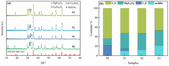
Figure 1.
XRD patterns of the oxidation slags with different copper slag additions: (a) XRD analysis; (b) Rietveld refinement analysis.
Figure 1b shows the results of the Rietveld refinement analysis of the XRD patterns [26,27], which demonstrates that the greatest MgFe2O4 content of 32.82% is achieved with the addition of 10% copper slag. However, when 15% copper slag is added, the content of melilite (Ca2MgSi2O7 and Ca2Al2SiO7) gradually increases, while the content of MgFe2O4 decreases, which is not conducive to MgFe2O4 formation. Figure 2 and Table 1 show the SEM-EDS analysis of the oxidation slags. As shown in Figure 2(a1,a2), the iron-containing phases in the S0 sample are MgFe2O4 and Ca2Fe2O5, and a large number of small-faced MgFe2O4 crystals form clusters of crystals. Furthermore, Figure 2(b1,b2) show that the MgFe2O4 in the S1 sample can be mainly divided into two different morphologies, namely honeycomb and clusters [28], and Ca2SiO4 and Ca2Fe2O5 are closely dispersed around MgFe2O4, preventing magnetic phase separation. As shown in Figure 2(c1,c2,d1,d2), with an increase in copper slag addition, the Ca2Fe2O5 phase disappears, and many small MgFe2O4 crystals gradually grow and aggregate into large polygonal crystals, with particles sizes of nearly 60 µm, indicating that the addition of copper slag obviously promotes the agglomeration and growth of MgFe2O4 [29]. However, the amount of melilite increases with the addition of 15% copper slag, as shown in Table 1. Melilite not only contains little Fe, but it also results in a decrease in Mg involved in the reaction, which is not conducive to the formation of MgFe2O4.
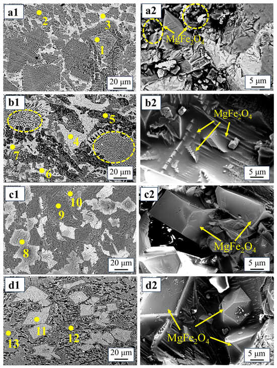
Figure 2.
Morphologies of MgFe2O4 with different copper slag additions: (a1,a2)—S0, 0%; (b1,b2)—S1, 5%; (c1,c2)—S2, 10%; (d1,d2)—S3, 15%.

Table 1.
Atomic percentages of the spectrum points corresponding to Figure 2 (wt %).
Moreover, all β-Ca2SiO4 phases of the oxidation slags contain phosphorus elements, suggesting that phosphorus elements do not migrate during the process. According to the literature [30,31], C2S exists in the crystal form of β-Ca2SiO4 rather than γ-Ca2SiO4, because phosphorus stabilizes β-Ca2SiO4 by replacing [SiO4]4− groups with [PO4]3− groups to form a Ca2SiO4–Ca3(PO4)2 solid solution. This prevents the volume instabilities caused by the transformation to γ-Ca2SiO4 and the phosphorus enrichment of MgFe2O4.
Figure 3 shows that, as the addition of copper slag rose from 0% to 5%, the oxidation degree of Fe2+ and the yield of MgFe2O4 increased dramatically. The formation of MgFe2O4 increased significantly from 60.32% to 86.57%, whereas the oxidation degree of Fe2+ remained roughly constant at 95.85% when the copper slag addition was greater than 10%. As a result, 10% copper slag addition was chosen for the subsequent experiments.
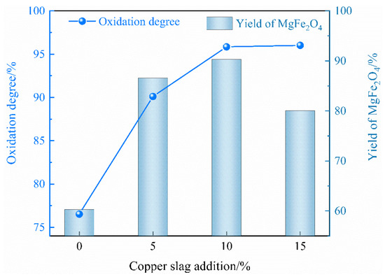
Figure 3.
Effects of copper slag addition on the oxidation degree of Fe2+ and the yield of magnetic MgFe2O4.
2.1.2. Effect of Oxidation Temperature
Figure 4 depicts the XRD results of the oxidation slags at different temperatures under the parameters of 10% copper slag addition and a 10 min oxidation period. The phases in the oxidation slags are β-Ca2SiO4, MgFe2O4 and melilite. The diffraction peak of MgFe2O4 increases initially and then decreases as the temperature increases, whereas the diffraction peak of melilite increases dramatically, presumably due to the Fe and Mg elements decomposing from MgFe2O4, forming melilite at high temperatures.
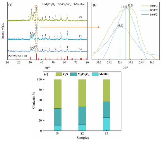
Figure 4.
XRD patterns of the oxidation slags at different temperatures: (a) XRD analysis; (b) 34.8° to 36.2° magnified image; (c) Rietveld refinement analysis.
Furthermore, together with the Rietveld refinement analysis, as shown in Figure 4c, it is found that the greatest content of MgFe2O4 is 34.91% at 1450 °C. Figure 4b depicts an enlarged version of the dotted line area in Figure 4a. According to Bragg′s law [32], the relationship between the diffraction angle and interplanar spacing is as shown in Equation (6):
where d is the interplanar spacing, θ is the diffraction angle, n is the diffraction order and λ is the wavelength of Cu-Kα radiation.
The diffraction angle shifts to greater angles as the interplanar separation decreases. The ionic radii of Fe3+ (0.64 Å) and Al3+ (0.51 Å) are similar, allowing Fe3+ to be replaced with Al3+, causing the diffraction angle of MgFe2O4 to become higher. As the temperature increased, more Al3+ was dissolved in MgFe2O4, resulting in the diffraction angle of MgFe2O4 shifting to greater angles. The doping of Al3+ will affect the distribution of cations in MgFe2O4, which will change the magnetism. Meanwhile, higher melilite content will decrease the formation of magnetic MgFe2O4.
The microstructures of the oxidation slags at temperatures ranging from 1400 to 1500 °C are shown in Figure 5, while Table 2 shows the atomic percentages of the relevant spectral spots. The yield of MgFe2O4 obtained through magnetic separation is closely related to its particle size. As shown in Figure 5a, the magnetic phases develop into tiny dendritic crystals along the direction of the nucleus. The size of the MgFe2O4 particles increases with the temperature, reaching a maximum of 60 µm, suggesting that a higher temperature can promote the formation and growth of MgFe2O4. Table 2 shows that the MgFe2O4 phase contains more Al at 1500 °C, indicating that higher temperatures can replace Fe3+ with Al3+. Therefore, an overly high oxidation temperature will inhibit the synthesis of MgFe2O4.
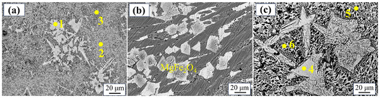
Figure 5.
Morphologies of MgFe2O4 at different temperatures: (a)—S4, 1400 °C; (b)—S2, 1450 °C; (c)—S5, 1500 °C.
Table 2.
Atomic percentages of the spectrum points corresponding to Figure 5 (wt %).
As shown in Figure 6, the influence of different oxidation temperatures on the oxidation degree of Fe2+ and the yield of MgFe2O4 is evident. It is observed that, with an increase in the oxidation temperature from 1400 to 1500 °C, there is a corresponding rise in the oxidation degree from 82.58% to 96.10%. This phenomenon can be attributed to the enhanced molecular diffusion rate at higher temperatures. An increase in the oxidation temperature can improve the kinetic conditions of the oxidation reaction and increase the mass transfer rate of iron ions (Fe2+ and Fe3+) and O2− in the slag, which is not only beneficial for the increase in the particle size of MgFe2O4, but also improves the yield of the magnetic phase in the magnetic separation process. Conversely, the yield of MgFe2O4 exhibits an initial increase, followed by a subsequent decrease, reaching a maximum value of 90.31% at an oxidation temperature of 1450 °C.
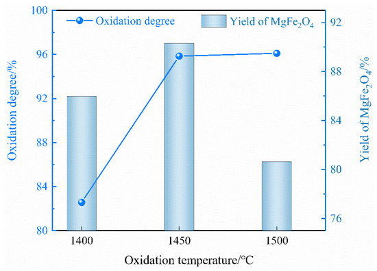
Figure 6.
Effect of oxidation temperature on the oxidation degree of Fe2+ and the yield of magnetic MgFe2O4.
2.1.3. Effect of Oxidation Time
Figure 7a,b show the XRD results and Rietveld refinement analysis, respectively, after different oxidation times, with 10% copper slag addition and an oxidation temperature of 1450 °C. The diffraction peak intensity and the content of β-Ca2SiO4 and MgFe2O4 are basically consistent, but those of melilite gradually increase.
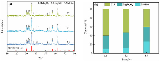
Figure 7.
XRD patterns of oxidation slags at different times: (a) XRD analysis; (b) Rietveld refinement analysis.
Figure 8 and Table 3 show the microstructures and EDS results of the oxidation slags, respectively. Figure 8a–c demonstrate that the magnetic phases are MgFe2O4, with the amount and size of the particles obviously increasing with an increase in the oxidation time, indicating that the oxidation time is conducive to the growth of the MgFe2O4 phase. In addition, the presence of phases such as β-Ca2SiO4 and melilite has been confirmed through XRD analysis. Furthermore, it has been observed that, with an oxidation time of 5 min, the formation of dendritic crystallites of MgFe2O4 particles occurs, and these particles undergo further development into a regular octahedron with an increase in the oxidation time. Under the same amount of copper slag addition and oxidation temperature, an increase in the oxidation time improves the oxidation degree and also facilitates the aggregation and growth of MgFe2O4 particles. With the increase in the oxidation time, the microstructure of the MgFe2O4 particles transforms from fine crystalline to polyhedral, and the size of the particles increases significantly, which is beneficial for subsequent magnetic separation.
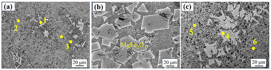
Figure 8.
Morphologies of MgFe2O4 after different oxidation times: (a)—S6,5 min; (b)—S2, 10 min; (c)—S7, 15min.
Table 3.
Atomic percentages of the spectrum points corresponding to Figure 8 (wt %).
However, an increase in the melilite content has been observed to disrupt the phase growth of MgFe2O4 at an oxidation time of 15 min, resulting in a reduction in the magnetite size, thereby hindering the separation of the magnetic phases.
Figure 9 illustrates the impact of different oxidation times on the oxidation degree of Fe2+ and the yield of MgFe2O4. The oxidation degree increases significantly with increasing oxidation times from 5 to 10 min. Nevertheless, when the oxidation time is extended to 15 min, the oxidation degree demonstrates a gradual upward trend, suggesting that the majority of the Fe2+ in the oxidation slags has been oxidized to Fe3+. Additionally, the yield of MgFe2O4 attained its maximum at 10 min, substantiating the recommendation of an oxidation time of 10 min.
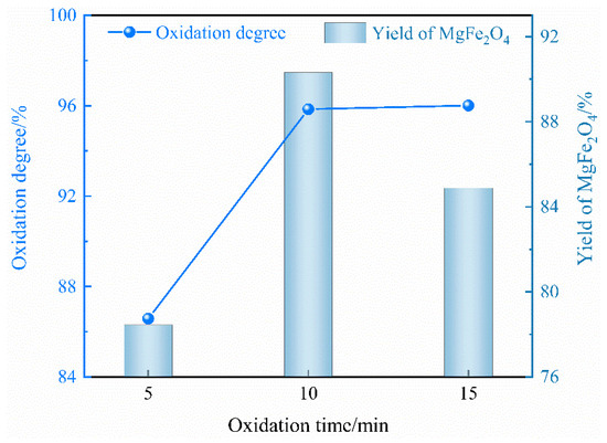
Figure 9.
Effect of oxidation time on oxidation degree of Fe2+ and yield of magnetic MgFe2O4.
2.2. Magnetic Separation Product Analysis
Table 4 shows the chemical compositions of the oxidation slags. It can be seen that, with an increase in copper slag addition, there is almost no FeO in the oxidation slag, indicating that the oxidation reaction is completed, and the FeO in the BOF slag and copper slag is oxidized to Fe2O3. Figure 10 shows the XRD results of the magnetic product and non-magnetic slag of the S2 sample after magnetic separation. The main phase of the magnetic product is MgFe2O4. Furthermore, as shown in Table 5, the main chemical components of the magnetic product are MgO and Fe2O3, indicating that the magnetic product is a highly pure magnetic MgFe2O4 material. The chemical composition of the non-magnetic slag is similar to that of a cement clinker. The content of free CaO and free MgO is 0.81% and 0.68%, respectively, which improves the stability of the BOF slag and makes it applicable for use as a construction material. The synergistic oxidation process of BOF slag and copper slag achieves the goal of the comprehensive utilization of metallurgical solid waste.
Table 4.
Chemical compositions of oxidation slags (wt%).
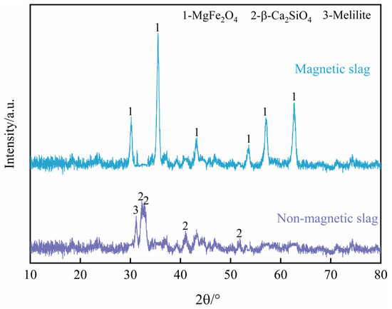
Figure 10.
XRD patterns of magnetic phase and non-magnetic slag of S2 sample.
Table 5.
Chemical composition of the product after the magnetic separation of the S2 sample (wt%).
3. Materials and Methods
3.1. Materials
The BOF slag and copper slag used in the experiment were taken from a steelmaking company and a copper-smelting plant in China, respectively. The chemical components of the two slags are listed in Table 6. The total content in BOF slag and copper slag was 17.76% and 44.73%, respectively; this was measured by chemical titration with potassium dichromate according to the national standards of GB/T 6730.65-2009 and GB/T 6730.8-2016 [33,34]. The other components were assessed through X-ray fluorescence (XRF) analysis.
Table 6.
Chemical compositions of BOF slag and copper slag (wt %).
XRD analysis was used with an X-ray diffractometer (X′pert PRO, PANalytical, Netherlands) to determine the phase compositions of the BOF slag and copper slag with Cu Kα radiation (40 kV, 40 mA, wavelength 0.154 nm), and the scanned angular range varied from 10° to 80° with a scanning speed of 0.2°/s. The XRD patterns of the two slags are presented in Figure 11. The main phases of BOF slag are dicalcium silicate (Ca2SiO4), dicalcium ferrite (Ca2Fe2O5), the RO phase, free lime and periclase, while copper slag consists of fayalite (Fe2SiO4) and magnetite (Fe3O4). Moreover, the content of f-CaO and f-MgO in the BOF slag were detected by chemical extraction according to the GB/T 176-2017 national standard and the studies of Uehara et al. and Hanada et al., respectively [35,36,37].
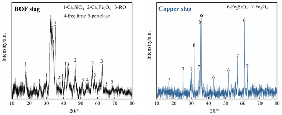
Figure 11.
XRD patterns of BOF slag and copper slag.
3.2. Experimental Procedure
The oxidation experiment was carried out in a high-temperature furnace (Shanghai Jujing Precision Instrument Manufacturing Co., Ltd., Shanghai, China), as shown in Figure 12a, while Figure 12b depicts the wet magnetic separator (XCGS-50, Beijing Grand BoYu Technology Co., Ltd., Beijing, China), with a maximum magnetic flux density of 300 mT. Here, 30 g BOF slag was placed in a corundum crucible, which was placed into the constant-temperature zone of the tube furnace. The BOF slag was heated to the target temperature (1400 °C, 1450 °C and 1500 °C) to simulate the molten state of BOF slag during discharge under a high-purity argon atmosphere and held for 10 min to uniformize the slag. Then, crushed copper slag particles with granularity of less than 74 µm and oxygen gas were simultaneously injected into the molten BOF slag through the hanging corundum tube (OD 8 mm, ID 6 mm), and the flow rate of the oxygen gas was 1 L/min. The range of copper slag addition was selected as 5% to 15%. When the oxidation time (5 min, 10 min and 15 min) was reached, the crucible was taken out and cooled in air at room temperature to obtain oxidation samples. The oxidation experiment’s conditions are shown in Table 7.
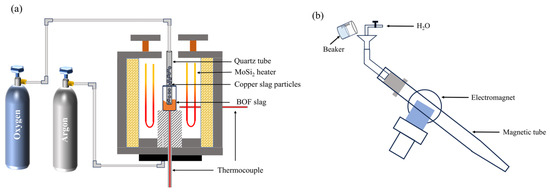
Figure 12.
Schematic diagram of the experimental equipment: (a) high-temperature furnace; (b) magnetic separator.
Table 7.
Oxidation experiment conditions.
Next, 10 g of the oxidation slag was ground in a ball mill, and magnetic separation was carried out in a wet magnetic separator with a magnetic tube. To ensure that the particles were completely moist, the dry sample was placed in a beaker and deionized water was added. Then, we slowly poured the sample from the beaker into a magnetic separation tube filled with water, and the magnetic phase in the oxidation slag adhered to the two magnetic poles on the tube wall under the action of electromagnetism, while the non-magnetic slag was discharged outside the tube with the water flow. Following magnetic separation, the obtained materials, including the magnetic material and non-magnetic slag, were oven-dried for further examination.
3.3. Characterization
The synergistic oxidation process of BOF slag and copper slag converts the Fe2+ from the two slags to Fe3+. Therefore, in order to better define the oxidation degree of Fe2+ in the oxidation slags, the concept of the oxidation degree is proposed in this work, as shown in Equation (5). Furthermore, the yields of magnetic MgFe2O4 following magnetic separation were determined based on Equation (6).
where w(Fe2+)m and w(Fe2+)o are the content of Fe2+ in the BOF slag and copper slag and the oxidation slag, respectively, %; γ is the yield of MgFe2O4, %; m1 is the content of MgFe2O4 theoretically generated, %; and m2 is the content of MgFe2O4 in the oxidation slag, %.
The content of TFe and Fe2+ in the oxidation slags was measured by chemical titration. The microstructure of the oxidation slags was characterized by scanning electron microscopy (Zeiss Ultra Plus, Germany) combined with energy-dispersive spectrometry (EDS), respectively.
4. Conclusions
The present study investigated the synergistic treatment of BOF slag and copper slag via oxidation–magnetic separation for the preparation of magnetic MgFe2O4 material and non-magnetic slag stabilization. The effects of the oxidation parameters on the phase transformation and the morphology of MgFe2O4 were also studied. The following conclusions can be drawn.
- (1)
- The addition of copper slag can facilitate the dicalcium ferrite in BOF slag and fayalite in copper slag to release simple iron oxides of FeO and Fe2O3, and it promotes the formation of magnetic MgFe2O4.
- (2)
- An increase in both the oxidation temperature and oxidation time resulted in an increase in the size of the MgFe2O4 particles, which is conducive to the separation of the magnetic MgFe2O4.
- (3)
- The optimal oxidation conditions include 10% addition of copper slag, an oxidation temperature of 1450 °C and a 10 min oxidation time, resulting in a maximum oxidation degree of Fe2+ and yield of MgFe2O4 of 95.85% and 90.31%, respectively.
- (4)
- This process results in the removal of free CaO and free MgO from the BOF slag, and the non-magnetic slag is predominantly composed of Ca2SiO4, which can be utilized as a construction material.
Author Contributions
Conceptualization, N.W.; methodology, N.W. and B.C.; validation, N.W. and M.C.; formal analysis, B.C.; investigation, B.C.; resources, N.W.; writing—original draft preparation, B.C.; writing—review and editing, N.W.; supervision, N.W. and M.C. All authors have read and agreed to the published version of the manuscript.
Funding
This research was funded by the National Natural Science Foundation of China, grant numbers 52274325 and 52374328.
Data Availability Statement
The data presented in this study are available on request from the corresponding author.
Conflicts of Interest
The authors declare no conflicts of interest.
References
- He, K.; Wang, L.; Li, X. Review of the energy consumption and production structure of China’s steel industry: Current situation and future development. Metals 2020, 10, 302. [Google Scholar] [CrossRef]
- Yildirim, I.Z.; Prezzi, M. Chemical, mineralogical, and morphological properties of steel slag. Adv. Civ. Eng. 2011, 2011, 463638. [Google Scholar] [CrossRef]
- Guo, J.; Bao, Y.; Wang, M. Steel slag in China: Treatment, recycling, and management. Waste Manag. 2018, 78, 318–330. [Google Scholar] [CrossRef] [PubMed]
- Gao, W.; Zhou, W.; Lyu, X.; Liu, X.; Su, H.; Li, C.; Wang, H. Comprehensive utilization of steel slag: A review. Powder Technol. 2023, 422, 118449. [Google Scholar] [CrossRef]
- Harichandan, B.; Venugopal, R. Effect of design parameters of magnetic separator on recovery of metal values from slag waste. Int. J. Environ. Waste Manag. 2023, 31, 500–513. [Google Scholar] [CrossRef]
- Vegas, I.; Oleaga, A.; García, C.V.; Santamaria, A.; Tomas San, J.J. Assessment of steelmaking slags subjected to accelerated carbonation. Ain Shams Eng. J. 2024, 15, 102790–102804. [Google Scholar] [CrossRef]
- Alex, T.C.; Mucsi, G.; Venugopalan, T.; Kumar, S. BOF steel slag: Critical assessment and integrated Approach for Utilization. J. Sustain. Metall. 2021, 7, 1407–1424. [Google Scholar] [CrossRef]
- Brand, A.S.; Roesler, J.R. Steel furnace slag aggregate expansion and hardened concrete properties. Cem. Concr. Compos. 2015, 60, 1–9. [Google Scholar] [CrossRef]
- Neto, J.B.F.; Fredericci, C.; Faria, J.O.G.; Chotoli, F.F.; Ribeiro, T.R.; Malynowskyj, A.; Silva, A.L.N.; Quarcioni, V.A.; Lotto, A.A. Modification of basic oxygen furnace slag for cement manufacturing. J. Sustain. Metall. 2017, 3, 720–728. [Google Scholar] [CrossRef]
- Naakase, K.; Matsui, A.; Nakai, Y.; Kikuchi, N.; Kishimoto, Y.; Tetsuyama, I. Development of Iron Recovery Technique from Steelmaking Slag by Reduction at High Temperature. ISIJ Int. 2023, 63, 429–435. [Google Scholar] [CrossRef]
- Harada, T.; Hirata, H.; Arai, T.; Toh, T.; Yamada, T. Development of the Molten Slag Reduction Process-1 Characteristics of Closed Type DC arc Furnace for Molten Slag Reduction. ISIJ Int. 2018, 58, 1934–1942. [Google Scholar] [CrossRef]
- Guo, H.; Yin, S.; Yu, Q.; Yang, X.; Huang, H.; Yang, Y.; Gao, F. Iron recovery and active residue production from basic oxygen furnace (BOF) slag for supplementary cementitious materials. Resour. Conserv. Recycl. 2018, 129, 209–218. [Google Scholar] [CrossRef]
- Hao, S.; Luo, G.; Wang, L.; An, S.; Chai, Y.; Song, W. Preparation of cementing material and recovery of iron resources using converter slag. Process. Saf. Environ. Prot. 2024, 190, 73–84. [Google Scholar] [CrossRef]
- Dai, W.; Li, Y.; Cang, D.; Liu, Z.; Fan, Y. BOF Slag Glass-ceramics Prepared in Different Atmospheres from Parents Glasses with Various Reduction Degree. ISIJ Int. 2014, 54, 2672–2677. [Google Scholar] [CrossRef]
- Lan, M.; He, Z.; Hu, X. Optimization of Iron Recovery from BOF Slag by Oxidation and Magnetic Separation. Metals 2022, 12, 742. [Google Scholar] [CrossRef]
- Xue, P.; He, D.; Xu, A.; Gu, Z.; Yang, Q.; Engström, F.; Björkman, B. Modification of industrial BOF slag: Formation of MgFe2O4 and recycling of iron. J. Alloys Compd. 2017, 712, 640–648. [Google Scholar] [CrossRef]
- He, Z.; Hu, X.; Chou, K.-C. Oxidative modification of industrial basic oxygen furnace slag for recover iron-containing phase: Study on phase transformation and mineral structure evolution. Process. Saf. Environ. 2023, 171, 167–175. [Google Scholar] [CrossRef]
- Li, Y.; Dai, W. Modifying hot slag and converting it into value-added materials: A review. J. Clean. Prod. 2018, 175, 176–189. [Google Scholar] [CrossRef]
- Tian, H.; Guo, Z.; Pan, J.; Zhu, D.; Yang, C.; Xue, Y.; Li, S.; Wang, D. Comprehensive review on metallurgical recycling and cleaning of copper slag. Resour. Conserv. Recycl. 2021, 168, 105366. [Google Scholar] [CrossRef]
- Cao, B.; Wang, N.; Zhang, C.; Chen, M. Co-modification of BOF slag and copper slag to recover valuable metals by carbothermal reduction. JOM 2023, 75, 3568–3576. [Google Scholar] [CrossRef]
- Jamal Uddin, M.; Jeong, Y.K. Application of magnesium ferrite nanomaterials for adsorptive removal of arsenic from water: Effects of Mg and Fe ratio. Chemosphere 2022, 307, 135817. [Google Scholar] [CrossRef] [PubMed]
- Kaur, N.; Kaur, M.; Singh, D. Fabrication of mesoporous nanocomposite of graphene oxide with magnesium ferrite for efficient sequestration of Ni (II) and Pb (II) ions: Adsorption, thermodynamic and kinetic studies. Environ. Pollut. 2019, 253, 111–119. [Google Scholar] [CrossRef] [PubMed]
- Shu, R.; Zhao, Z.; Yang, X. Fabrication of nitrogen-doped reduced graphene oxide/porous magnesium ferrite@silica dioxide composite with excellent dual-band electromagnetic absorption performance. Chem. Eng. J. 2023, 473, 145224. [Google Scholar] [CrossRef]
- Liu, C.; Huang, S.; Blanpain, B.; Guo, M. Optimization of mineralogy and microstructure of solidified basic oxygen furnace slag through SiO2 addition or atmosphere control during hot-stage slag treatment. Metall. Mater. Trans. B 2018, 50, 210–218. [Google Scholar] [CrossRef]
- Tian, T.; Li, G.; Li, Y.; Li, T.; Yuan, C.; Liu, Y. Thermodynamics and kinetics on hot state modification of BOF slag by adding SiO2. Metall. Mater. Trans. B 2023, 54, 1131–1143. [Google Scholar] [CrossRef]
- Talero, R.; Trusilewicz, L.; Delgado, A.; Pedrajas, C.; Lannegrand, R.; Rahhal, V.; Mejía, R.; Delvasto, S.; Ramírez, F.A. Comparative and semi-quantitative XRD analysis of Friedel’s salt originating from pozzolan and Portland cement. Constr. Build. Mater. 2011, 25, 2370–2380. [Google Scholar] [CrossRef]
- Cuevas, J.; Cabrera, M.Á.; Fernández, C.; Mota-Heredia, C.; Fernández, R.; Torres, E.; Turrero, M.J.; Ruiz, A.I. Bentonite Powder XRD Quantitative Analysis Using Rietveld Refinement: Revisiting and Updating Bulk Semiquantitative Mineralogical Compositions. Minerals 2022, 12, 772. [Google Scholar] [CrossRef]
- Lin, Y.; Liu, Y.; Chou, K.; Shu, Q. Effects of oxygen atmosphere, FeOx and basicity on mineralogical phases of CaO–SiO2–MgO–Al2O3–FetO–P2O5 steelmaking slag. Ironmak. Steelmak. 2018, 46, 1470362. [Google Scholar] [CrossRef]
- Ma, Y.; Du, X. Influence of CaO addition, FeO/SiO2, and MgO/SiO2 on the melting characteristic temperatures of FeO-SiO2-MgO-CaO System. Mater. Res. 2019, 22, e20180645. [Google Scholar] [CrossRef]
- Duée, C.; Bourgel, C.; Véron, E.; Allix, M.; Fayon, F.; Bodénan, F.; Poirier, J. Phosphorus speciation in dicalcium silicate phases: Application to the basic oxygen furnace (BOF) slag. Cem. Concr. Res. 2015, 73, 207–214. [Google Scholar] [CrossRef]
- Gautier, M.; Poirier, J.; Bodénan, F.; Franceschini, G.; Véron, E. Basic oxygen furnace (BOF) slag cooling: Laboratory characteristics and prediction calculations. Int. J. Miner. Process. 2013, 123, 94–101. [Google Scholar] [CrossRef]
- Andreozzi, G.B.; Lucchesi, S. Intersite distribution of Fe2+ and Mg in the spinel (sensu stricto)–hercynite series by single-crystal X-ray diffraction. Am. Miner. 2002, 87, 1113–1120. [Google Scholar] [CrossRef]
- GB/T 6730.65-2009; Iron Ores—Determination of Total Iron Content-Titanium (III) Chloride Reduction Potassium Dichromate Titration Methods (Routine Methods). Standards Press of China: Beijing, China, 2009.
- GB/T 6730.8-2016; Iron Ores—Determination of Iron (II) Content—Potassium Dichromate Titrimetric Method. Standards Press of China: Beijing, China, 2016.
- GB/T 176-2017; Methods for Chemical Analysis of Cement. Standards Press of China: Beijing, China, 2017.
- Uehara, N.; Takita, M. Extraction of free magnesia from steelmaking slags using Iodine–Ethanol solutions. ISIJ Int. 2018, 58, 1474–1479. [Google Scholar] [CrossRef]
- Hanada, K.; Inose, M.; Sato, S.; Watanabe, K.; Fujimoto, K. Development of analytical methods for free-MgO in steelmaking slag. Tetsu Hagane-J. Iron Steel Inst. Jpn. 2016, 102, 24–28. [Google Scholar] [CrossRef]
Disclaimer/Publisher’s Note: The statements, opinions and data contained in all publications are solely those of the individual author(s) and contributor(s) and not of MDPI and/or the editor(s). MDPI and/or the editor(s) disclaim responsibility for any injury to people or property resulting from any ideas, methods, instructions or products referred to in the content. |
© 2025 by the authors. Licensee MDPI, Basel, Switzerland. This article is an open access article distributed under the terms and conditions of the Creative Commons Attribution (CC BY) license (https://creativecommons.org/licenses/by/4.0/).