Article

In-Situ Alloy-Modified Sodiophilic Current Collectors for Anode-Less Sodium Metal Batteries

1
School of Material Science and Engineering, Anhui University, Hefei 230601, China
2
Hefei National Laboratory for Physical Sciences at the Microscale, Department of Materials Science and Engineering, CAS Key Laboratory of Materials for Energy Conversion, University of Science and Technology of China, Hefei 230026, China
*
Authors to whom correspondence should be addressed.
These authors contributed equally to this work.
Batteries 2023, 9(8), 408; https://doi.org/10.3390/batteries9080408
Submission received: 17 June 2023 / Revised: 26 July 2023 / Accepted: 2 August 2023 / Published: 4 August 2023
(This article belongs to the Special Issue High-Performance Materials for Sodium-Ion Batteries)

Abstract

:
Anode-less sodium metal batteries have drawn dramatica attention owing to their high specific energy and low cost. However, the growth of sodium dendrites and the resulting loss of active materials and serious safety concerns hinder their practical applications. In this work, a bismuth-based modification layer with good sodiophilicity is constructed on the surface of Cu foil (denoted as Cu@Bi) to control the deposition of Na metal. The activation-derived porous Na-rich alloy phase can provide abundant nucleation sites and reduce the nucleation overpotential to induce the uniform and dense deposition of Na metal. When evaluated in half cell, the Cu@Bi current collectors can operate for 750 h at 1 mA cm−2 and 1 mAh cm−2, with an average coulombic efficiency (CE) of 99.5%. When the current density is improved to 2 mA cm−2, the Cu@Bi can also stably maintain for 750 cycles, demonstrating the remarkable effect of the modification layer. When coupled with the Na3V2(PO4)3 cathode, the full cell exhibits stable cycle performance over 80 cycles. The modification strategy of alloy modification can provide fresh ideas for the research and application of anode-less and even anode-free metal batteries.

Graphical Abstract

1. Introduction

In recent years, considering the uneven global distribution of lithium resources and rising prices, many new energy storage systems have received widespread attention, including sodium-ion batteries (SIBs), potassium-ion batteries, supercapacitors, et al. [1,2,3,4]. As one of the most promising alternatives to lithium, sodium (Na), with its natural abundance, low electrochemical voltage (–2.73 V vs. SHE) and high theoretical capacity of Na metal anode (1165 mAh g−1) has been considered as a promising charge carrier [5,6,7,8]. Recently, rechargeable batteries based on Na metal anode have drawn much attention, including Na-S batteries [9,10], Na-Se batteries [11,12] and Na-O2 batteries [13]. Among all sodium metal batteries (SMBs), the anode-less or anode-free sodium metal batteries are considered the best choice because of their higher energy density, lower cost and easier cell preparation [14,15].
It is worth noting that the development of Na metal anode is severely limited by uncontrolled dendrite growth and the side reaction with serious performance deterioration [16,17]. The parasitic reactions mainly occur on the interface of Na metal and electrolyte due to the high chemical reactivity of Na, which will generate unstable solid electrolyte interphase (SEI) during repeated cycling [18,19]. Dendrite growth is a vicious cycle that leads to a large loss of active sodium and serious safety concerns. Compared with traditional sodium metal batteries, anode-less SMBs face greater challenges due to the lack of supplementary sodium on the negative electrode side [20,21]. Therefore, it is particularly important to limit the occurrence of side reactions and reduce the loss of active Na metal. In order to solve the above problems, researchers have carried out a variety of different attempts, mainly including the following three strategies: (1) prioritization of electrolyte composition [22,23,24]; (2) construction of three-dimensional sodiophilic current collectors [25,26]; (3) structural design and surface modification of current collectors [27]. For example, Li et al. coated MOF-derived nanocomposites on Cu foil and Al foil and achieved a stable cycle of 600 cycles [26]. Modulation of sodiophilic nucleation sites to optimize metal deposition and lower the overpotential of nucleation/growth has been taken as one of the most promising tactics for guiding the nucleation and growth behavior of Na metal [28,29,30].
Alloy-based anode materials, such as tin (Sn) [31,32], antimony (Sb) [33,34,35] and bismuth (Bi) [36,37,38], are a type of electrode materials for sodium-ion batteries that can produce alloy reaction with Na ions. Notably, the integration of sodiophilic alloys shows outstanding potential to stabilize Na metal due to its high affinity to Na [39]. Bismuth (Bi) is a typical alloy-based anode material, which has been intensively investigated in SIBs [40]. During the discharge/charge process, Bi undergoes the reversible reaction of Bi ↔ NaBi ↔ Na3Bi. It is worth noting that Na-rich alloy shows a low Na+ diffusion barrier and high binding energy of Na [41,42,43,44].
Here in, we design and construct a Bi modification layer on the Cu foil (denoted as Cu@Bi) via a simple liquid-phase in situ reduction reaction. After the activation process, the bismuth nanoparticles transform into a sodiophilic Na-rich alloy phase with a porous structure. This unique porous sodiophilic structure has the following advantages when used for regulating the deposition of Na metal: On one hand, uniform porous structure helps to induce homogeneous deposition of sodium metal, forming a uniform and dense sodium metal layer, and avoiding dendrite growth; On the other hand, the Na-rich alloys with a high affinity for sodium are beneficial to reduce the overpotential of sodium metal deposition and accelerate the reaction kinetics of SMBs. These characteristics enable higher coulombic efficiency (CE) and lower voltage hysteresis, when used as a current collector for Na plating/stripping. The Cu@Bi can achieve a long lifespan of 750 h at 1 mA cm−2 and 1 mAh cm−2, with an average CE of up to 99.5%. When the current collector improved to 2 mA cm−2 the Cu@Bi can also stably maintain for 750 cycles, with an average CE up to 99.6%. The full cell coupled with the Na3V2(PO4)3 (NVP) cathode shows sustainable cycle performance over 80 cycles.

2. Materials and Methods

2.1. Chemicals

The copper foil was purchased from Neware Technology Limited; ethanol, acetone, acetonitrile (anhydrous, 99.8%), hydrochloride acid (HCl, 36.5 wt%), Bismuth nitrate (Bi(NO3)3·5H2O, 98%), nitric acid (HNO3, 70 wt%) were all purchased from Sinopharm Chemical Reagent Co., Ltd in Shanghai, China.

2.2. Synthesis of Cu@Bi

The Cu foil was washed with DI water, acetone and 1M HCl solution successively and rose with DI water and ethanol respectively. Then, Bi(NO3)3·5H2O was solved in a mixed solution of acetonitrile and water (volume ratio 1:1), during which nitric acid was added to obtain a clear solution. The as-cleaned Cu foil was immersed into the above solution for 10 s, followed by washing with DI water immediately. After drying in a vacuum oven, the alloy-modified Cu foil (denoted with Cu@Bi) was collected.

2.3. Material Characterization

The phase composition of the as-prepared samples was carried out via X-ray diffraction (XRD) using Philips X’Pert PRO SUPER with Cu-Kα radiation. The morphology characterization was performed via Scanning electron microscopy (SEM) using Zeiss Supra 40 at an acceleration voltage of 5 kV and transmission electron microscopy (TEM) using HT7800. The chemical environment of the surface atoms was characterized via X-ray photoelectron spectroscopy (XPS) on ESCALab MKII.

2.4. Electrochemical Measurement

All electrochemical characterization was carried out via CR2032 coin cells. The Cu@Bi foil was directly punched into disks (Φ = 12 mm). The electrochemical performance of the Cu@Bi and Bare Cu were evaluated via half cell, symmetric cell and full cell. The half cell was assembled with the Cu@Bi or Bare Cu disks as the working electrode and sodium metal foil as the counter and reference electrode. The Cu@Bi and Bare Cu undergo an activation process before plating/striping of Na metal, including three discharge/charge cycles and a discharge process. To assemble the symmetric cell, the Cu@Bi and Bare Cu disk was first deposited with 1.5 mAh sodium metal in half cells. Then, the half cells were disassembled and reassembled with two deposited current collectors. For the full cell, the anode is the Cu@Bi and Bare Cu after activation and pre-deposition. The NVP cathode was prepared from a slurry that contained 70 wt% NVP powder, 20 wt% conductive carbon black, and 10 wt% PVDF. The slurry was coated onto the carbon-coated Al foil with a mass loading of ~2 mg cm−2. All batteries were tested via a galvanostatic charging-discharging test system (Neware CT-ZWJ-4) at 25 °C.

3. Results and Discussion

3.1. Material Characterization

The synthesis schematic for the Cu@Bi current collector is shown in Figure 1a. When a piece of copper foil is immersed into the mix solution, the contact surface immediately darkens to black, indicating that bismuth was in-situ coated on the surface of the as-cleaned Cu foil. During the rapid reaction process, copper(I) tetrakisacetonitrile salt and Bi are generated via the redox reaction of Cu and Bi3+ in the presence of acetonitrile, as the following reaction equation [45]:
3 Cu ( s ) + 12 MeCN + Bi 3 + 3 Cu ( MeCN ) 4 + + Bi ( s )
The proposed mechanism of the induced Na deposition on the Cu@Bi current collector is illustrated in Figure 1b. When the bismuth coated Cu foil was used as a current collector for SMBs, the Bi layer first underwent two stepwise alloy reaction process, as shown in following equations:
Bi + Na+ + e = NaBi
NaBi + 2 Na+ + 2e = Na3Bi
The Na-Bi alloy has been proven sodiophilic and will guide the Na deposition process. The porous morphology of Na-Bi alloy can homogenize ion flow and facilitate the uniform deposition of Na+, leading to a uniform and dense Na-deposited layer. As a comparison, the Bare Cu exhibits sodiophobic surface properties and microscopically uneven topography, which results in an inhomogeneous current density distribution. The electric field concentrates at the protruding, inducing uneven Na deposits and worsening dendrite formation during the subsequent plating process.
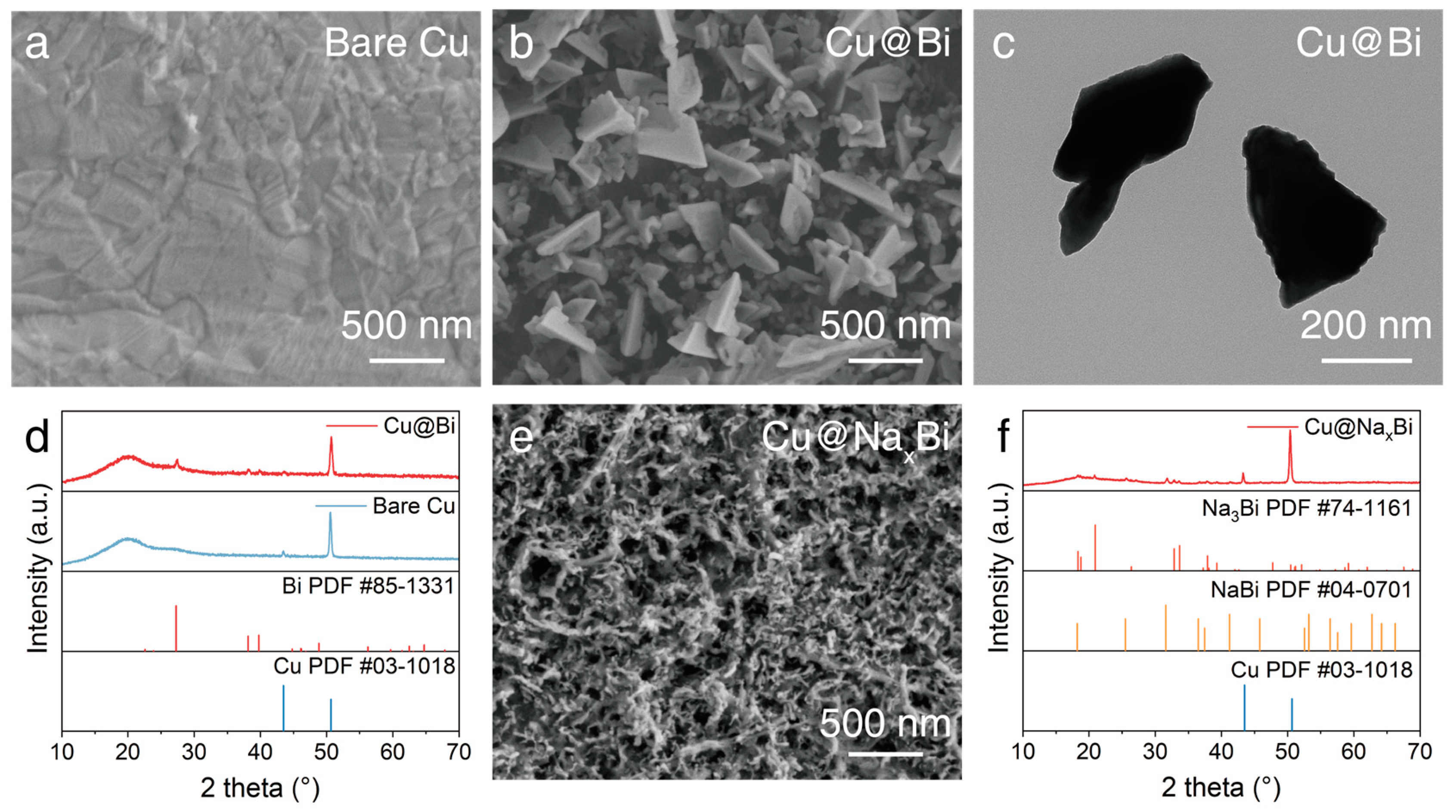
SEM, TEM and XRD were employed to reveal the synthesis process of the Cu@Bi current collector. As shown in Figure 2a and Figure S1, the Bare Cu shows overall flatness, but local unevenness. It can be seen from the enlarged SEM image that there are many sharp bumps and grooves on the surface of the copper foil. After galvanic replacement of Bi3+ by Cu, bismuth tetrahedron grow on the copper surface (Figure 2b,c and Figure S2). The TEM image illustrates that the bismuth tetrahedron and bismuth particles are about 200 nm in size. Figure 2d shows the typical XRD patterns of the Cu@Bi current collector, revealing that the material is well-crystallized. The peaks at 27.3°, 38.1° and 39.7° are consistent with the standard XRD pattern of metallic Bi (JCPDS 85-1331), confirming the galvanic replacement reaction between Cu foil and Bi3+ in the mixed solution. The small hump around 17–18° is assigned to the polyimide (PI) tape, which is used to protect the sample from reaction with air. After three pre-cycles, the bismuth layer is transformed into a three-dimensional porous Na-Bi alloy (Figure 2e). Obviously, the porous and smoother surface of the Cu@Bi current collector after cycling will homogenize ion flow and facilitate the uniform deposition of Na+, inducing the homogenous and dense deposition of the Na metal layer. In addition, sodium-bismuth alloy has good sodiophilicity, which can induce uniform deposition of sodium ions, and the porous structure can provide a better deposition effect. The XRD pattern of the Cu@Bi current collector after cycling (Figure 2f) illustrates the disappearance of the peaks of metallic Bi and the generation of new phases. The peaks at 20.8°, 32.8° and 33.6° match the characteristic diffraction peaks of the tetragonal Na3Bi (JCPDS 74-1161), corresponding to the lattice plane of (1 1 1), (1 1 0) and (1 0 3), respectively. The peaks at 25.6°, 31.8° and 36.7° are assigned to the NaBi (JCPDS 04-0701), corresponding to the lattice plane of (1 0 0), (1 0 1) and (1 1 0), respectively. It’s worth noting that the Bi on the Cu current collector should completely transform into Na3Bi after being discharged to 0.01 V, according to the alloy reaction mechanism of Bi anode in sodium ion batteries. The main reason for the appearance of the NaBi alloy phase is that Na3Bi is unstable when in contact with air, and it is easy to decompose to produce NaBi or even Bi. Sodium-bismuth alloy has good sodiophilicity, which can induce uniform deposition of sodium ions.

3.2. Electrochemical Performance

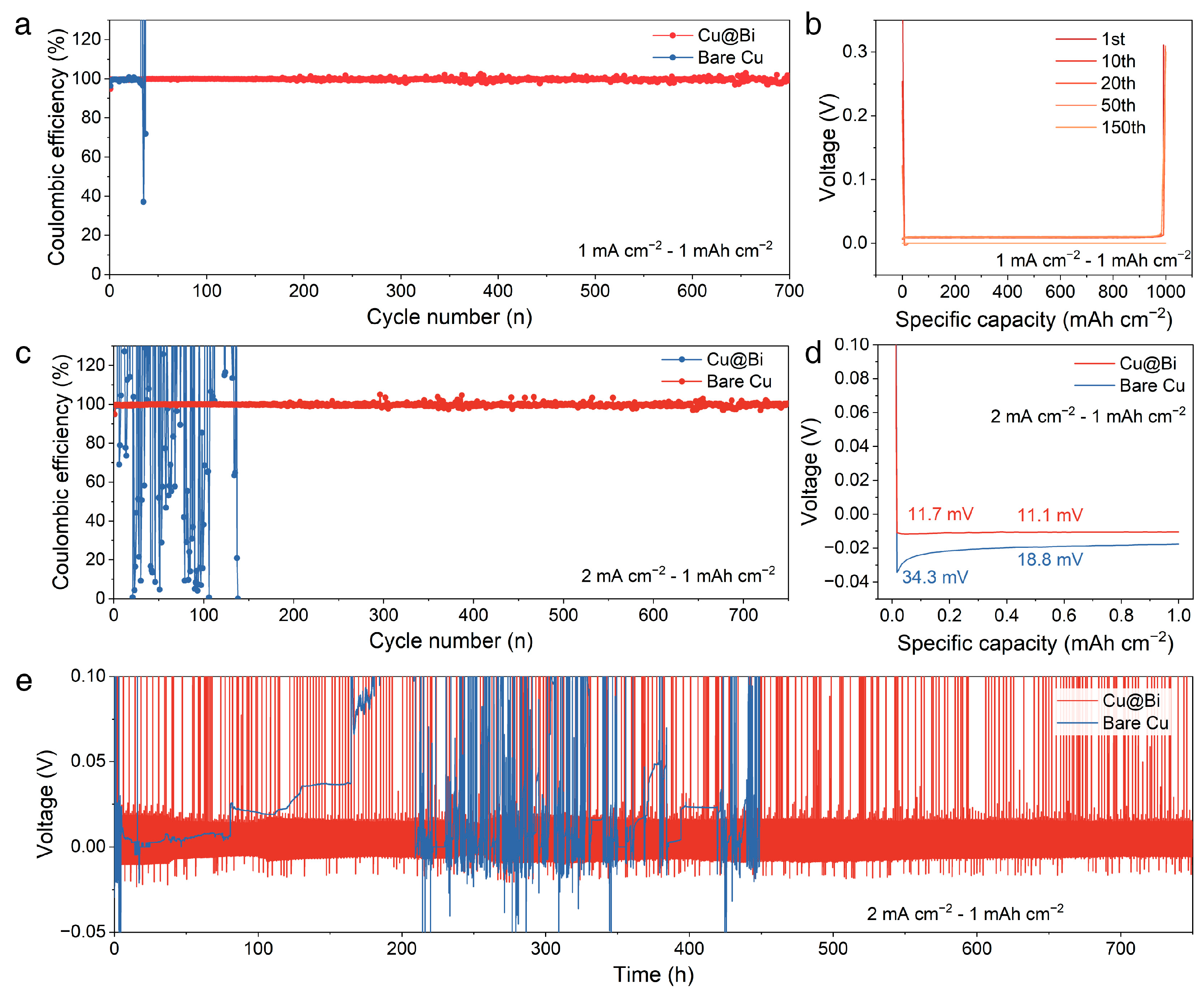
The Na metal anode performances were evaluated via assembling the half cells with the Cu@Bi and the Bare Cu as the working electrode and Na metal foil as counter and reference electrode, denoted as the Cu@Bi||Na and the Bare Cu||Na. It is worth noting that, via the activation process before the electrochemical deposition and striping, the Bi nanoparticles of the Cu@Bi would be transformed into the Na-Bi alloy phase. As shown in Figure S3a, the discharge/charge curves of the activation process of the Cu@Bi exhibit typical discharge/charge curves of the Bi-based anode [40,46,47]. In the initial discharge process, there is a slope voltage range from 1.31 V to 0.67 V and two distinct voltage plateaus located at 0.65 V and 0.49 V, respectively, which are assigned to the formation of SEI film and the stepwise electrochemical alloy reactions of Na3Bi ↔ NaBi ↔ Bi. The next three cycles all showed a typical alloying reaction process without regeneration of fresh SEI, reflecting the stability of the surface modification layer. The final step of activation stops at discharge to 0.01 V, followed by Na metal deposition and stripping tests. In contrast, pure copper yields almost negligible specific capacity during activation (Figure S3b). In an SMBs system, the value of Coulombic efficiency (CE) can reflect the deactivation rate of the Na metal during the repeatedly plating/striping process, which can be a significant electrochemical performance indicator. As shown in Figure 3a, the Cu@Bi||Na can constantly cycle for 350 cycles at 1 mA cm−2 with Na deposition capacities of 1 mA h cm−2, exhibiting an average CE up to 99.5%. In comparison, the bare Cu||Na can only cycle for 38 cycles. Therefore, the Bi-modified Cu current collector can offer much more stable Na deposition. The plating overpotential is also an important evaluation standard for metal anode because it represents the nucleation barrier of the Na deposition. As shown in Figure 3b, the Cu@Bi||Na exhibits a plating overpotential of 3.5 mV in the initial stage of the Na deposition, which is much smaller than that of the Bare Cu (26.2 mV, Figure S4). During the growth stage of Na metal, the overpotential of the Cu@Bi||Na is close to 0 mV, compared with 15.8 mV for the Bare Cu||Na. The much lower plating overpotential is mainly owed to the outstanding sodiophilicity of the Na-Bi alloy on the surface of the Cu@Bi. The overpotential of the Cu@Bi||Na is generally stable throughout the cycles with slightly increasing after cycling for 300 h (Figure 3b and Figure S5). In comparison, the voltage profile of the Bare Cu||Na (Figure S6) shows a long pause during 68–205 h, which is due to the soft short circuit inside the half-cell, reflecting the presence of substantial dendrite growth. Subsequent reluctant cycles still cannot change the fact that the battery has failed. The half-cells were also tested at higher current density (Figure 3c). The Cu@Bi||Na half-cell is cycled at 2 mA cm−2 with Na deposition capacities of 1 mA h cm−2 for 750 cycles. The CE of the Cu@Bi||Na is still maintained above 99%, with an average of 99.6%. As a comparison, the plating/striping of Na metal on the Bare Cu exhibits severe instability. The plating overpotential of the Cu@Bi||Na is much lower than that of the Bare Cu||Na (Figure 3d). When cycling at 2 mA cm−2, the nucleation overpotential of the Na metal on the Cu@Bi is 11.7 mV and the growth overpotential is 11.1 mV. In comparison, in the first cycle, the overpotential for the nucleation and growth on the Bare Cu are 34.2 and 18.8 mV, respectively. The voltage profiles of the Cu@Bi||Na and Bare Cu||Na are shown in Figure 3e and Figure S7, illustrating the stable cycling performance of the Cu@Bi. For the Cu@Bi||Na, the plating/striping process of Na metal on the Cu@Bi maintains stably for 750 h, with the nucleation overpotential less than 25 mV and the growth overpotential around 8 mV. In comparison, the Bare Cu||Na can only cycle stably for 3 cycles, followed by severe dendrite growth or even a short circuit. Therefore, the Na-Bi alloy-modified layer on the Cu current collector can not only reduce the overpotential of the electrochemical reaction but also guide the uniform deposition of Na metal to avoid dendrite growth and improve the utilization rate of active substances.
To evaluate the role of the nucleation layer of the Cu@Bi current collector, the deposition behaviors on the surface of the activated Cu@Bi current collector and the Bare Cu are deeply investigated. The morphologies of the deposited Na metal layer with 1 mAh cm−2 were characterized via SEM (Figure 4). The low magnification (200×) image of deposited Na on the Cu@Bi exhibits a smooth and dense surface, indicating that the Bi modification layer does favor inducing uniform deposition and growth of Na metal (Figure 4a). The higher magnification (500× and 1000×) images further reveal the dense and island-like morphology of Na metal deposition on the Cu@Bi (Figure 4b,c) [48]. In comparison, when the same capacity of sodium metal is deposited on Bare Cu, the Na metal deposition layer exhibits obvious inhomogeneity and porosity. The low magnification image (Figure 4d) evidently exhibits the inhomogeneous deposition of Na metal, with thick deposition in some places and uncovered copper in others, which can be due to the high nucleation barrier and random nucleation process [26]. In larger magnification images, dendrite-like Na deposition can be observed, which can be due to the uneven Na+ deposition (Figure 4e,f). The optical images of 1 mAh cm−2 Na metal plated on the Cu@Bi and the Bare Cu are shown in Figure S8, which allow a more intuitive understanding of the importance of the bismuth-modified layer for inducing the homogeneous deposition of Na metal. Moreover, the difference in the cross-sectional view of the Na deposited layer between the Cu@Bi and the Bare Cu can be clearly visualized. For the Cu@Bi, the Na metal layer exhibits a consistent thickness and a dense bulk structure, intuitively reflecting the process of uniform deposition of Na ions. As a comparison, the Na metal deposition layer on the Bare Cu surface exhibits a porous and loose structure and non-uniform thickness. The porous structure will lead to more electrolyte consumption and SEI growth, resulting in increased electrode impedance and slower reaction kinetics. Notably, the porous structure of the Na metal deposition layer differs from that of Na-Bi alloys because the latter is more stable in structure and won’t lead to more electrolyte consumption and SEI growth after the activation process. Therefore, the Na-rich alloy significantly enhances the ability of the current collector to induce nucleation and growth of Na metal, contributing to the formation of a dense and uniform Na metal deposition layer, and improving the safety and reaction kinetics of Na metal anodes.
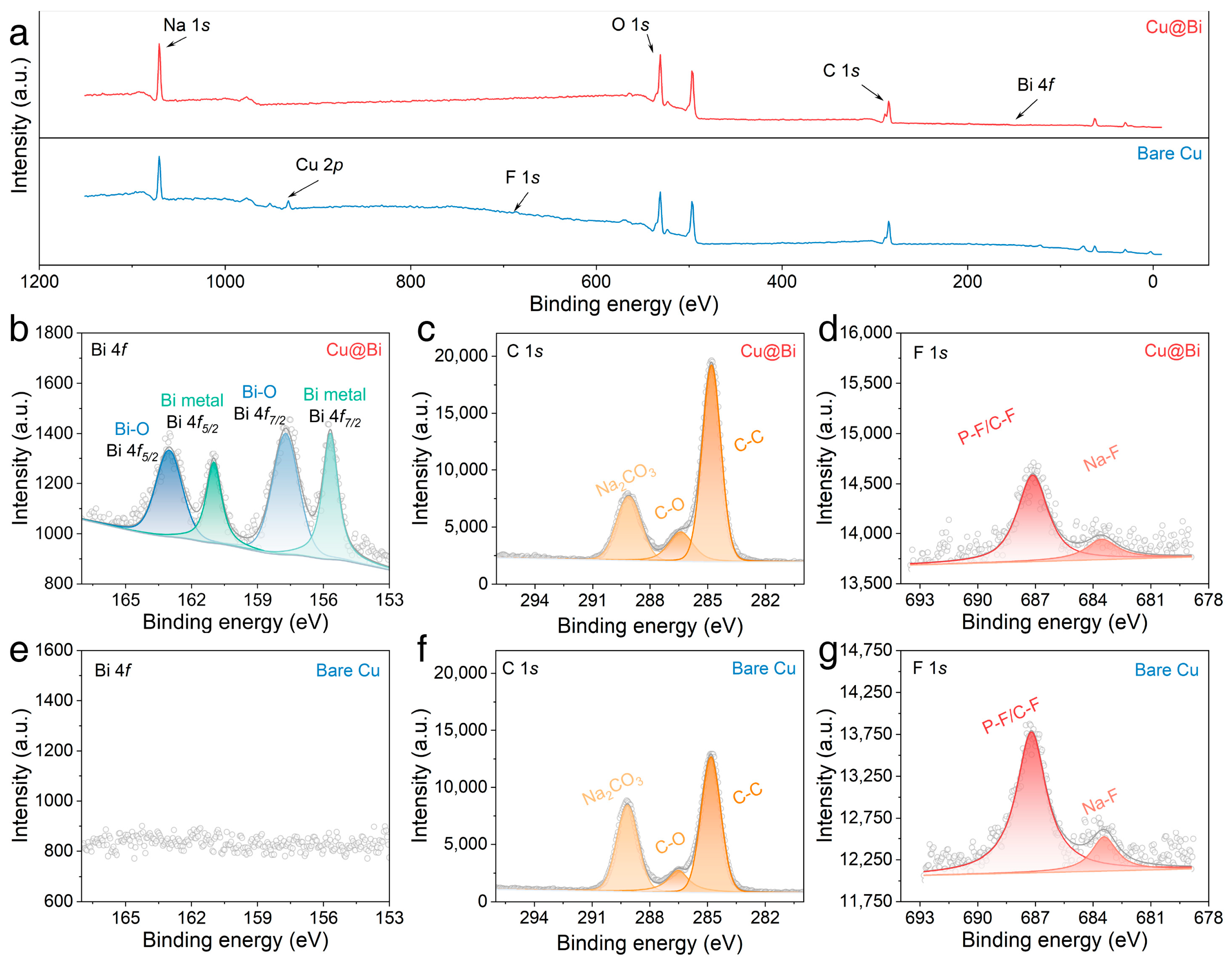
To confirm the reaction between the electrolyte and the deposited Na metal, the surface compositions of the Cu@Bi and the Bare Cu after 10 cycles were investigated via XPS. The five main peaks of the XPS survey spectra corresponded to Na 1s, Cu 2p, F 1s, O 1s, C 1s, and Bi 4f, respectively (Figure 5a). The Bi 4f spectrum of the Cu@Bi in Figure 5b shows two peaks at 155.7 eV (Bi 4f7/2) and 160.1 eV (Bi 4f5/2), which correspond to metallic Bi or zero-valent Bi. The other two peaks at 157.7 and 163.0 eV are attributed to Bi 4f7/2 and Bi 4f5/2 of the oxidation state of Bi on the surface of the sample, which is mainly due to the surface oxidation of NaxBi when exposed to air [49]. In comparison, the sample of Bare Cu shows no signal for the high resolution of Bi 4f spectra (Figure 5e). It is well known that the SEI film composition has a significant impact on electrochemical performance. Therefore, the high resolution of the C 1s and F 1s spectra are investigated to unveil the composition and structure of the SEI films. For the Cu@Bi after cycling, the C 1s spectrum can be deconvoluted into three peaks at 289.1, 286.4 and 284.8, corresponding to Na2CO3, C–O, and C–C, respectively (Figure 5c) [50]. Therefore, the peak of Na2CO3 is attributed to inorganic composites in SEI film, while the peaks of C–O and C–C are assigned to the organic ingredients resulting from the decomposition of the electrolyte solvent during the charge and discharge process. The C 1s spectrum of the Bare Cu after cycling exhibits a similar composition, whereas the intensity ratio of the peaks of Na2CO3 and the peaks of C–C in the Bare Cu is significantly increased compared with that in the Cu@Bi sample, reflecting that the SEI film of the Bare Cu is composed by more inorganic ingredients (Figure 5f). The F 1s spectrum of the Cu@Bi can be deconvoluted into two peaks at 687.1 and 683.5, corresponding to P–F/C–F and Na–F, respectively [49]. The fluorinated ingredients are mainly owing to the decomposition of the sodium hexafluorophosphate (NaPF6). Thereinto, P–F/C–F correspond to the formation of organic fluorine-containing compounds, while the Na-F corresponds to the formation of the sodium fluoride (NaF) inorganic salt component. Compared with the Cu@Bi, the intensity of the F 1s for the Bare Cu is relatively stronger, reflecting that more electrolyte was consumed to generate more SEI film during cycling for the Bare Cu. It is worth noting that the SEI composition of the Cu@Bi includes a part of the SEI generated on the bismuth surface. Therefore, the Bi-modified layer reduces the formation of SEI by inducing the uniform deposition of Na metal to form a uniform and dense Na metal deposition layer, which is beneficial to promote the electrode reaction kinetics and safety. In contrast, the random deposition of Na+ on the surface of the Bare Cu produces a loose and porous sodium metal layer and sodium dendrites, which consumes more electrolyte and is prone to safety problems such as internal short circuits in the batteries.
To further investigate the suitability of the Cu@Bi current collector for practical SMBs, the coin-type full cell (Cu@Bi||NVP and Bare Cu||NVP) were assembled using NaPF6/DME solution as electrolyte. Na3V2(PO4)3 (NVP) is a typical polyphosphate cathode material and a NASICON material with great cycling stability and stable thermal stability, which has been widely investigated. The NVP was prepared according to our previous work, with XRD pattern and SEM images shown in Figure S9 and Figure S10, respectively [51]. The NVP cathode was pre-cycled with Na metal as a counter electrode before assembling the full cells. Figure S11 shows the charge/discharge curves of the NVP at 1C (1 C = 110 mAh g−1). After the first cycle, the charge-specific capacity of the NVP@C-BN stabilized at 100 mAh g−1. In order to assemble the full cell, both the Cu@Bi and the Bare Cu underwent three cycles of activation process and pre-deposited with 0.1 mAh of Na. The cycling performance of the Cu@Bi is much more stable than that of the Bare Cu (Figure 6). For the Cu@Bi, in the first charge curve, there is a sloping plateau and a flat plateau at 3.39 V, which can be assigned to the CEI formation and the desodiation process. The charge/discharge specific capacity in the initial cycle is 122.7 and 97.6 mAh g−1, respectively, with an initial Coulombic efficiency (ICE) of 79.5% (Figure 6a). During the subsequent cycles, the Cu@Bi||NVP delivers almost overlapping charge and discharge curves and increasing CE. In comparison, the charge/discharge curves of the Bare Cu||NVP show severe distortion with the increasing of the cycling number. The Bare Cu||NVP delivers charge/discharge capacities of 105.0/91.2, 94.2/91.1, 93.3/90.3, 73.7/61.8, 38.4/32.0 and 14.6/10.7 mAh g−1 in the 1st, 2nd, 5th, 10th, 15th and 20th cycles, respectively (Figure 6b). As shown in Figure S12, the CE of the Bare Cu||NVP dramatically decreases after 7 cycles, with the CE of the most of cycles below 80%. The low CE indicates that a considerable portion of Na cannot be reversibly returned to the cathode in the cycle. Figure 6c shows the cycling performance of the two samples at 1C. The Cu@Bi||NVP delivers stable cycling performance after 80 cycles with a reversible specific capacity of 95.6 mAh g−1 and a high and stable CE of around 99.2%. In comparison, the Bare Cu||NVP can only be cycled seven times stably, which further confirms that the Bi modification layer can dramatically prolong the lifespan of the Na metal anode.

4. Conclusions

In summary, a Bi-modified Cu current collector was developed via a simple acetonitrile assisted electrostatic displacement reaction as the anode for SMBs. After the activation process, the Bi modification layer transformed into porous and sodiophilic Na-Bi alloy, which can not only induce uniform deposition of sodium metal, forming a uniform and dense sodium metal layer, but also reduce the deposition overpotential and accelerate the reaction kinetics of SMBs. When used as a current collector for Na plating/stripping, the Cu@Bi can achieve a long lifespan of 750 h at 1 mA cm−2 and 1 mAh cm−2, with an average CE up to 99.5%, demonstrating that the dendrite was significantly suppressed. Even at 2 mA cm−2, the Cu@Bi can still stably maintain over 750 cycles, with an average CE of up to 99.6%. The full cell coupled with the Na3V2(PO4)3 (NVP) cathode shows sustainable cycle performance over 80 cycles, indicating its application prospect. This work presents an approach to regulate the Na metal nucleation and growth, which paves the way for the development of SMBs with high energy density and high safety.

Supplementary Materials

The following supporting information can be downloaded at: https://www.mdpi.com/article/10.3390/batteries9080408/s1, Figure S1: (a) The SEM image of the Cu@Bi. (b) The TEM image of the dendrite Bi. Figure S2: The activation process of (a) the Cu@Bi and (b) the Bare Cu. Figure S3: The voltage profile of the Bare Cu||Na at 1 mA cm−2 and 1 mAh cm−2. Figure S4: The voltage-time curves of the Cu@Bi||Na at 1 mA cm−2 and 1 mAh cm−2. Figure S5: The voltage-time curves of the Bare Cu||Na at 1 mA cm−2 and 1 mAh cm−2. Figure S6: The optical image of 1 mAh cm−2 Na metal plated on (a) the Cu@Bi and (b) the Bare Cu. Figure S7: The XRD pattern of the NVP@C-BN. Figure S8: The SEM images of the NVP@C-BN. Figure S9: The voltage profiles of the NVP@C-BN when cycling at 1C. Figure S10: The coulombic efficiency of the Bare Cu||NVP at 1C. Figure S11: The voltage profiles of the Bare Cu||NVP at 1C in 15th cycle. Figure S12: The coulombic efficiency of the Bare Cu||NVP at 1C.

Author Contributions

X.C. and D.L. designed this work and conduct the characterization. S.P. assembled the cells. X.C. and D.L. discussed the results and prepared the first draft of the manuscript. P.S. provided some research ideas and valuable discussions. H.Y. and Y.J. provided some research ideas and cathode materials. Y.J. and S.L. supervised, coordinated the work, and provided funding. All authors have read and agreed to the published version of the manuscript.

Funding

This work was supported by the National Natural Science Foundation of China (Nos. 52172174, 52002083, 52102321, 52102322), the key research and development projects in Anhui Province (202004a07020026) and the Program of Anhui Scientific and Technical Leaders Reserve Candidates (2018RH168).

Data Availability Statement

Data supporting the findings of this study are available from the corresponding author upon reasonable request.

Conflicts of Interest

The authors declare no conflict of interest.

References

  1. Zhao, Z.; Zhao, X.; Zhou, Y.; Liu, S.; Fang, G.; Liang, S. Towards establishing uniform metrics for evaluating the safety of lithium metal batteries. Adv. Powder Mater. 2023, 2, 100139. [Google Scholar] [CrossRef]
  2. Wang, K.; Zhang, Z.; Cheng, S.; Han, X.; Fu, J.; Sui, M.; Yan, P. Precipitate-stabilized surface enabling high-performance Na0.67Ni0.33-xMn0.67ZnxO2 for sodium-ion battery. eScience 2022, 2, 529–536. [Google Scholar] [CrossRef]
  3. Xiong, C.; Yang, Q.; Dang, W.; Zhou, Q.; Jiang, X.; Sun, X.; Wang, Z.; An, M.; Ni, Y. A multifunctional paper-based supercapacitor with excellent temperature adaptability, plasticity, tensile strength, self-healing, and high thermoelectric effects. J. Mater. Chem. A 2023, 11, 4769–4779. [Google Scholar] [CrossRef]
  4. Xiong, C.; Zhang, Y.; Xu, J.; Dang, W.; Sun, X.; An, M.; Ni, Y.; Mao, J. Kinetics process for structure-engineered integrated gradient porous paper-based supercapacitors with boosted electrochemical performance. Nano Res. 2023, 16, 9471–9479. [Google Scholar] [CrossRef]
  5. Guo, Z.; Qian, G.; Wang, C.; Zhang, G.; Yin, R.; Liu, W.-D.; Liu, R.; Chen, Y. Progress in electrode materials for the industrialization of sodium-ion batteries. Prog. Nat. Sci. Mater. Int. 2023, 33, 1–7. [Google Scholar] [CrossRef]
  6. Hao, Y.; Shao, J.; Yuan, Y.; Li, X.; Xiao, W.; Sari, H.M.K.; Liu, T.; Lu, J. Design of phosphide anodes harvesting superior sodium storage: Progress, challenges, and perspectives. Adv. Funct. Mater. 2023, 33, 2212692. [Google Scholar] [CrossRef]
  7. Yuan, M.; Liu, H.; Ran, F. Fast-charging cathode materials for lithium & sodium ion batteries. Mater. Today 2023, 63, 360–379. [Google Scholar]
  8. Zuo, W.; Innocenti, A.; Zarrabeitia, M.; Bresser, D.; Yang, Y.; Passerini, S. Layered oxide cathodes for sodium-ion batteries: Storage mechanism, electrochemistry, and techno-economics. Acc. Chem. Res. 2023, 56, 284–296. [Google Scholar] [CrossRef]
  9. Lei, Y.J.; Liu, H.W.; Yang, Z.; Zhao, L.F.; Lai, W.H.; Chen, M.; Liu, H.; Dou, S.; Wang, Y.X. A review on the status and challenges of cathodes in room-temperature Na-S batteries. Adv. Funct. Mater. 2022, 33, 2212600. [Google Scholar] [CrossRef]
  10. Ma, J.; Wang, M.; Zhang, H.; Shang, Z.; Fu, L.; Zhang, W.; Song, B.; Lu, K. Toward the advanced next-generation solid-state Na-S batteries: Progress and prospects. Adv. Funct. Mater. 2023, 33, 2214430. [Google Scholar] [CrossRef]
  11. Dong, W.-D.; Li, Y.; Li, C.-F.; Hu, Z.-Y.; Hsu, L.-C.; Chen, L.-H.; Li, Y.; Lei, A.; Su, B.-L. Atomically dispersed Co-N4C2 catalytic sites for wide-temperature Na-Se batteries. Nano Energy 2023, 105, 108005. [Google Scholar] [CrossRef]
  12. Li, J.; Song, J.; Luo, L.; Zhang, H.; Feng, J.; Zhao, X.; Guo, X.; Dong, H.; Chen, S.; Liu, H.; et al. Synergy of mxene with Se infiltrated porous n-doped carbon nanofibers as janus electrodes for high-performance sodium/lithium–selenium batteries. Adv. Energy Mater. 2022, 12, 2200894. [Google Scholar] [CrossRef]
  13. Jiang, C.; Zhang, H.; Li, P.; Zhan, X.; Liu, Z.; Wang, L.; Mao, B.; Li, Q.; Wen, Z.; Peng, Z.; et al. A highly stable all-solid-state Na–O2/H2O battery with low overpotential based on sodium hydroxide. Adv. Funct. Mater. 2022, 32, 2202518. [Google Scholar] [CrossRef]
  14. Wang, Y.; Dong, H.; Katyal, N.; Hao, H.; Liu, P.; Celio, H.; Henkelman, G.; Watt, J.; Mitlin, D. A Sodium-Antimony-Telluride Intermetallic Allows Sodium-Metal Cycling at 100% Depth of Discharge and as an Anode-Free Metal Battery. Adv. Mater. 2022, 34, 2106005. [Google Scholar] [CrossRef] [PubMed]
  15. Yang, T.; Luo, D.; Liu, Y.; Yu, A.; Chen, Z. Anode-free sodium metal batteries as rising stars for lithium-ion alternatives. iScience 2023, 26, 105982. [Google Scholar] [CrossRef]
  16. Chen, Q.; Zhang, T.; Hou, Z.; Zhuang, W.; Sun, Z.; Jiang, Y.; Huang, L. Large-scale sodiophilic/buffered alloy architecture enables deeply cyclable Na metal anodes. Chem. Eng. J. 2022, 433, 133270. [Google Scholar] [CrossRef]
  17. Chen, Q.; Zhuang, W.; Hou, Z.; Jiang, Y.; Wan, J.; Zhang, T.; Zhao, Y.; Huang, L. A dual-function additive to regulate nucleation behavior and interfacial chemistry for ultra-stable Na metal anodes beyond one year. Adv. Funct. Mater. 2023, 33, 2210206. [Google Scholar] [CrossRef]
  18. Li, D.; Sun, Y.; Li, M.; Cheng, X.; Yao, Y.; Huang, F.; Jiao, S.; Gu, M.; Rui, X.; Ali, Z.; et al. Rational design of an artificial SEI: Alloy/solid electrolyte hybrid layer for a highly reversible Na and K metal anode. ACS Nano 2022, 16, 16966–16975. [Google Scholar] [CrossRef]
  19. Wang, Z.; Huang, Z.; Wang, H.; Li, W.; Wang, B.; Xu, J.; Xu, T.; Zang, J.; Kong, D.; Li, X.; et al. 3D-printed sodiophilic V2CTx/rGO-CNT mxene microgrid aerogel for stable Na metal anode with high areal capacity. ACS Nano 2022, 16, 9105–9116. [Google Scholar] [CrossRef]
  20. Ma, B.; Lee, Y.; Bai, P. Dynamic interfacial stability confirmed by microscopic optical operando experiments enables high-retention-rate anode-free Na metal full cells. Adv. Sci. 2021, 8, 2005006. [Google Scholar] [CrossRef]
  21. Dahunsi, O.J.; Gao, S.; Kaelin, J.; Li, B.; Abdul Razak, I.B.; An, B.; Cheng, Y. Anode-free Na metal batteries developed by nearly fully reversible Na plating on the Zn surface. Nanoscale 2023, 15, 3255–3262. [Google Scholar] [CrossRef]
  22. Li, K.; Zhang, J.; Lin, D.; Wang, D.W.; Li, B.; Lv, W.; Sun, S.; He, Y.B.; Kang, F.; Yang, Q.H.; et al. Evolution of the electrochemical interface in sodium ion batteries with ether electrolytes. Nat. Commun. 2019, 10, 725. [Google Scholar] [CrossRef] [Green Version]
  23. Louli, A.J.; Eldesoky, A.; Weber, R.; Genovese, M.; Coon, M.; de Gooyer, J.; Deng, Z.; White, R.T.; Lee, J.; Rodgers, T.; et al. Diagnosing and correcting anode-free cell failure via electrolyte and morphological analysis. Nat. Energy 2020, 5, 693–702. [Google Scholar] [CrossRef]
  24. Lu, Z.; Yang, H.; Yang, Q.H.; He, P.; Zhou, H. Building a beyond concentrated electrolyte for high-voltage anode-free rechargeable sodium batteries. Angew. Chem. Int. Ed. 2022, 61, 202200410. [Google Scholar] [CrossRef] [PubMed]
  25. Lee, K.; Lee, Y.J.; Lee, M.J.; Han, J.; Lim, J.; Ryu, K.; Yoon, H.; Kim, B.H.; Kim, B.J.; Lee, S.W. A 3D hierarchical host with enhanced sodiophilicity enabling anode-free sodium-metal batteries. Adv. Mater. 2022, 34, 2109767. [Google Scholar] [CrossRef] [PubMed]
  26. Li, H.; Zhang, H.; Wu, F.; Zarrabeitia, M.; Geiger, D.; Kaiser, U.; Varzi, A.; Passerini, S. Sodiophilic current collectors based on MOF-derived nanocomposites for anode-less na-metal batteries. Adv. Energy Mater. 2022, 12, 2202293. [Google Scholar] [CrossRef]
  27. Wang, C.; Zheng, Y.; Chen, Z.N.; Zhang, R.; He, W.; Li, K.; Yan, S.; Cui, J.; Fang, X.; Yan, J.; et al. Robust anode-free sodium metal batteries enabled by artificial sodium formate interface. Adv. Energy Mater. 2023, 13, 2204125. [Google Scholar] [CrossRef]
  28. Mubarak, N.; Rehman, F.; Ihsan-Ul-Haq, M.; Xu, M.; Li, Y.; Zhao, Y.; Luo, Z.; Huang, B.; Kim, J.K. Highly sodiophilic, defect-rich, lignin-derived skeletal carbon nanofiber host for sodium metal batteries. Adv. Energy Mater. 2022, 12, 2103904. [Google Scholar] [CrossRef]
  29. Zhang, S.J.; You, J.H.; He, Z.; Zhong, J.; Zhang, P.F.; Yin, Z.W.; Pan, F.; Ling, M.; Zhang, B.; Lin, Z. Scalable lithiophilic/sodiophilic porous buffer layer fabrication enables uniform nucleation and growth for lithium/sodium metal batteries. Adv. Funct. Mater. 2022, 32, 2200967. [Google Scholar] [CrossRef]
  30. Zhao, L.; Hu, Z.; Huang, Z.; Tao, Y.; Lai, W.H.; Zhao, A.; Liu, Q.; Peng, J.; Lei, Y.; Wang, Y.X.; et al. In situ plating of mg sodiophilic seeds and evolving sodium fluoride protective layers for superior sodium metal anodes. Adv. Energy Mater. 2022, 12, 2200990. [Google Scholar] [CrossRef]
  31. Wu, X.; Lan, X.; Hu, R.; Yao, Y.; Yu, Y.; Zhu, M. Tin-based anode materials for stable sodium storage: Progress and perspective. Adv. Mater. 2022, 34, 2106895. [Google Scholar] [CrossRef] [PubMed]
  32. Zhu, Y.; Yao, Q.; Shao, R.; Wang, C.; Yan, W.; Ma, J.; Liu, D.; Yang, J.; Qian, Y. Microsized gray tin as a high-rate and long-life anode material for advanced sodium-ion batteries. Nano Lett. 2022, 22, 7976–7983. [Google Scholar] [CrossRef] [PubMed]
  33. Liu, Y.; Qing, Y.; Zhou, B.; Wang, L.; Pu, B.; Zhou, X.; Wang, Y.; Zhang, M.; Bai, J.; Tang, Q.; et al. Yolk-shell Sb@Void@Graphdiyne nanoboxes for high-rate and long cycle life sodium-ion batteries. ACS Nano 2023, 17, 2431–2439. [Google Scholar] [CrossRef] [PubMed]
  34. Nguyen, A.-G.; Le, H.T.T.; Verma, R.; Vu, D.-L.; Park, C.-J. Boosting sodium-ion battery performance using an antimony nanoparticle self-embedded in a 3D nitrogen-doped carbon framework anode. Chem. Eng. J. 2022, 429, 132359. [Google Scholar] [CrossRef]
  35. Xie, M.; Li, C.; Ren, S.; Ma, Y.; Chen, X.; Fan, X.; Han, Y.; Shi, Z.; Feng, S. Ultrafine Sb nanoparticles in situ confined in covalent organic frameworks for high-performance sodium-ion battery anodes. J. Mater. Chem. A 2022, 10, 15089–15100. [Google Scholar] [CrossRef]
  36. Kim, Y.-H.; An, J.-H.; Kim, S.-Y.; Li, X.; Song, E.-J.; Park, J.-H.; Chung, K.Y.; Choi, Y.-S.; Scanlon, D.O.; Ahn, H.-J.; et al. Enabling 100C fast-charging bulk Bi anodes for Na-ion batteries. Adv. Mater. 2022, 34, 2201446. [Google Scholar] [CrossRef]
  37. Liang, Y.; Song, N.; Zhang, Z.; Chen, W.; Feng, J.; Xi, B.; Xiong, S. Integrating Bi@C nanospheres in porous hard carbon frameworks for ultrafast sodium storage. Adv. Mater. 2022, 34, 2202673. [Google Scholar] [CrossRef]
  38. Li, Z.; Zhang, Y.; Zhang, J.; Cao, Y.; Chen, J.; Liu, H.; Wang, Y. Sodium-ion battery with a wide operation-temperature range from −70 to 100 °C. Angew. Chem. Int. Ed. 2022, 61, 202116930. [Google Scholar]
  39. Xu, F.; Qu, C.; Lu, Q.; Meng, J.; Zhang, X.; Xu, X.; Qiu, Y.; Ding, B.; Yang, J.; Cao, F.; et al. Atomic Sn–enabled high-utilization, large-capacity, and long-life Na anode. Sci. Adv. 2022, 8, eabm7489. [Google Scholar] [CrossRef]
  40. Cheng, X.; Shao, R.; Li, D.; Yang, H.; Wu, Y.; Wang, B.; Sun, C.; Jiang, Y.; Zhang, Q.; Yu, Y. A self-healing volume variation three-dimensional continuous bulk porous bismuth for ultrafast sodium storage. Adv. Funct. Mater. 2021, 31, 2011264. [Google Scholar] [CrossRef]
  41. Xiong, J.; Kushwaha, S.; Krizan, J.; Liang, T.; Cava, R.J.; Ong, N.P. Anomalous conductivity tensor in the Dirac semimetal Na3Bi. EPL 2016, 114, 27002. [Google Scholar] [CrossRef] [Green Version]
  42. Ye, S.; Wang, L.; Liu, F.; Shi, P.; Yu, Y. Integration of homogeneous and heterogeneous nucleation growth via 3D alloy framework for stable Na/K metal anode. eScience 2021, 1, 75–82. [Google Scholar] [CrossRef]
  43. Ma, M.; Lu, Y.; Yan, Z.; Chen, J. In situ synthesis of a bismuth layer on a sodium metal anode for fast interfacial transport in sodium-oxygen batteries. Batter. Supercaps 2019, 2, 663–667. [Google Scholar] [CrossRef]
  44. Yang, G.; Li, N.; Sun, C. High-performance sodium metal batteries with sodium–bismuth alloy anode. ACS Appl. Energy Mater. 2020, 3, 12607–12612. [Google Scholar] [CrossRef]
  45. Zhang, X.; Sun, X.; Guo, S.-X.; Bond, A.M.; Zhang, J. Formation of lattice-dislocated bismuth nanowires on copper foam for enhanced electrocatalytic CO2 reduction at low overpotential. Energy Environ. Sci. 2019, 12, 1334–1340. [Google Scholar] [CrossRef]
  46. Pu, B.; Liu, Y.; Bai, J.; Chu, X.; Zhou, X.; Qing, Y.; Wang, Y.; Zhang, M.; Ma, Q.; Xu, Z.; et al. Iodine-ion-assisted galvanic replacement synthesis of bismuth nanotubes for ultrafast and ultrastable sodium storage. ACS Nano 2022, 16, 18746–18756. [Google Scholar] [CrossRef]
  47. Qiu, X.; Wang, X.; He, Y.; Liang, J.; Liang, K.; Tardy, B.L.; Richardson, J.J.; Hu, M.; Wu, H.; Zhang, Y.; et al. Superstructured mesocrystals through multiple inherent molecular interactions for highly reversible sodium ion batteries. Sci. Adv. 2021, 7, eabh3482. [Google Scholar] [CrossRef]
  48. Wu, Z.; Wang, C.; Hui, Z.; Liu, H.; Wang, S.; Yu, S.; Xing, X.; Holoubek, J.; Miao, Q.; Xin, H.L.; et al. Growing single-crystalline seeds on lithiophobic substrates to enable fast-charging lithium-metal batteries. Nat. Energy 2023, 8, 340–350. [Google Scholar] [CrossRef]
  49. Cheng, X.; Sun, Y.; Li, D.; Yang, H.; Chen, F.; Huang, F.; Jiang, Y.; Wu, Y.; An, X.; Yu, Y. From 0D to 3D: Dimensional control of bismuth for potassium storage with superb kinetics and cycling stability. Adv. Energy Mater. 2021, 11, 2102263. [Google Scholar] [CrossRef]
  50. Luo, J.; Zhang, Y.; Matios, E.; Wang, P.; Wang, C.; Xu, Y.; Hu, X.; Wang, H.; Li, B.; Li, W. Stabilizing sodium metal anodes with surfactant-based electrolytes and unraveling the atomic structure of interfaces by Cryo-TEM. Nano Lett. 2022, 22, 1382–1390. [Google Scholar] [CrossRef]
  51. Jiang, Y.; Zhou, X.; Li, D.; Cheng, X.; Liu, F.; Yu, Y. Highly reversible Na storage in Na3V2(PO4)3 by optimizing nanostructure and rational surface engineering. Adv. Energy Mater. 2018, 8, 1800068. [Google Scholar] [CrossRef]
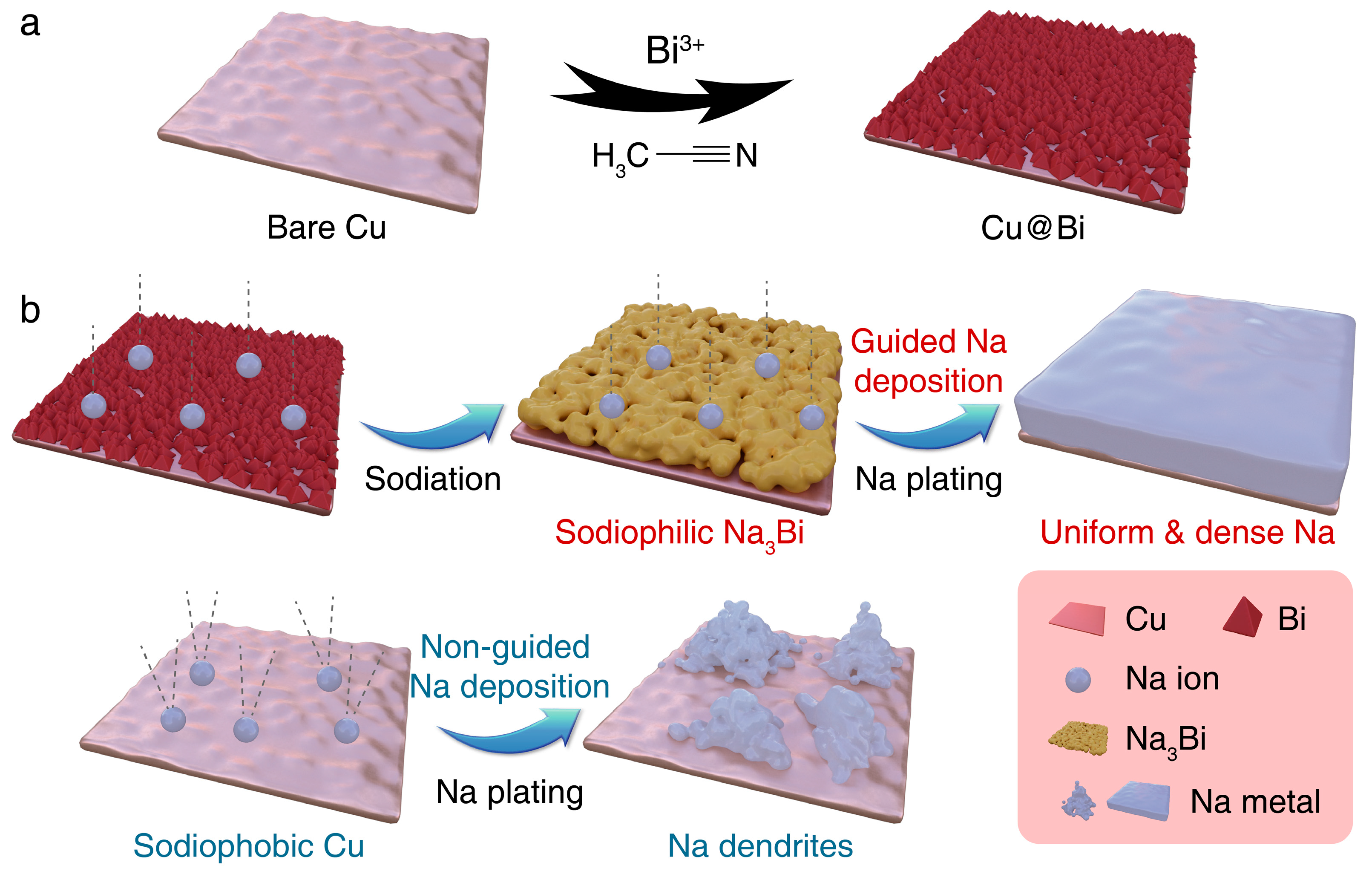
Figure 1. (a) Schematic diagram of the preparation of the Cu@Bi; (b) Schematic illustration of the Na deposition on the Cu@Bi and Bare Cu.
Batteries 09 00408 g001
Figure 2. (a) SEM image of the Bare Cu; (b) SEM image of the Cu@Bi; (c) TEM image of the deposited Bi nanoparticles; (d) XRD patterns of the Bare Cu and the Cu@Bi; (e,f) SEM image and XRD pattern of the Cu@NaxBi.
Batteries 09 00408 g002
Figure 3. (a) CE of Na plating/stripping at 1 mA cm−2 and 1 mAh cm−2 for Cu@Bi||Na and the Bare Cu||Na. (b) The voltage profiles of the Cu@Bi at 1 mA cm−2. (c) CE of Na plating/stripping at 2 mA cm−2 and 1 mAh cm−2 for the Cu@Bi||Na and the Bare Cu||Na. (d) The voltage profiles upon galvanostatic Na plating/stripping on the Cu@Bi and the Bare Cu at 2 mA cm−2. (e) The voltage profiles of the Cu@Bi||Na and the Bare Cu||Na at 2 mA cm−2 and 1 mAh cm−2.
Batteries 09 00408 g003
Figure 4. SEM images at different magnifications of (ac) the Cu@Bi and (df) the Bare Cu; SEM images of the cross section of (g) the Cu@Bi and (h) the Bare Cu after 1 mAh cm−2 Na plating.
Batteries 09 00408 g004
Figure 5. XPS spectra of the Cu@Bi and Bare Cu after cycling. (a) Survey spectra. High revolution XPS spectra of (b,e) Bi 4f; (c,f) C 1s; (d,g) F 1s.
Batteries 09 00408 g005
Figure 6. (a,b) Voltage profiles of the Cu@Bi||NVP and the Bare Cu||NVP; (c) Cycling performance of the Cu@Bi||NVP and the Bare Cu||NVP at 1C.
Batteries 09 00408 g006
Disclaimer/Publisher’s Note: The statements, opinions and data contained in all publications are solely those of the individual author(s) and contributor(s) and not of MDPI and/or the editor(s). MDPI and/or the editor(s) disclaim responsibility for any injury to people or property resulting from any ideas, methods, instructions or products referred to in the content.