Article

Anion and Cation Co-Modified Vanadium Oxide for Cathode Material of Aqueous Zinc-Ion Battery

1
Key Laboratory of Advanced Ceramics and Machining Technology of the Ministry of Education, School of Materials Science and Engineering, Tianjin University, Tianjin 300072, China
2
Applied Physics Department, College of Physics and Materials Science, Tianjin Normal University, Tianjin 300387, China
*
Authors to whom correspondence should be addressed.
Batteries 2023, 9(7), 352; https://doi.org/10.3390/batteries9070352
Submission received: 25 May 2023 / Revised: 23 June 2023 / Accepted: 28 June 2023 / Published: 2 July 2023

Abstract

:
Aqueous zinc-ion batteries (ZIBs) have been regarded as a promising alternative to traditional lithium-based batteries due to their intrinsic advantages of safety, low cost, and abundance. However, the strong electrostatic interaction between Zn2+ and the layer-structured cathodes is still a key issue that hinders the batteries from storing more Zn. Herein, we report partially nitrided and cation-doped vanadium oxide for improved Zn storage performance. Specifically, the defects and nitride species that are generated inside the material upon nitriding improve the conductivity of the material and introduce a new Zn storage mechanism. The intercalation of cations, in contrast, widens the interlayer spacing to store more Zn2+ ions and enhances the cycling stability of the material. These merits synergistically lead to significantly enhanced electrochemical Zn2+ ion storage performance, in terms of a high specific capacity of 418.5 mAh·g−1 at a current density of 0.1 A·g−1 and a capacity retention of 81.2% after 500 cycles at 2.0 A·g−1. The new modification strategy for V2O5 suggested in this work could provide insight into the development of high-performance ZIBs.

1. Introduction

In recent years, the shortcomings of lithium-ion batteries (LIBs) have gradually emerged. For example, toxic and flammable organic electrolytes and the high cost of mining lithium ore limit the application of LIBs in energy storage. Therefore, aqueous zinc-ion batteries (ZIBs) are proposed to solve these problems. Zinc metal can be used directly as the anode in this system [1]. The unique advantages of zinc metal anodes include high theoretical gravimetric capacity (820 mAh g−1) and volumetric capacity (5855 mAh·cm−3) [2], relatively low redox potential (−0.76 V vs. standard hydrogen electrodes) [3], and better stability in weakly acidic electrolytes compared to other metal elements (e.g., Mg, Ca, Al, etc.). In addition, compared with alkali metal-ion batteries (Li+, Na+, K+), Zn2+ involves two-electron transfer during the charge/discharge process [4]. Therefore, as an ideal green energy storage system, ZIBs have received more attention; furthermore, they are expected to have good application prospects.
However, the type of cathode materials has not been optimally selected for practical ZIBs. Therefore, developing a suitable cathode that is capable of storing Zn2+ at a high capacity has become the major focus in ZIBs research. Currently, vanadium-based compounds are the most widely studied cathode materials for ZIBs. Both vanadium oxides and vanadates have a layered or tunnel structure for the diffusion and storage of Zn2+. Vanadium oxides, such as V2O5 [5,6,7], VO2 [8,9], VOOH [10], V3O7 [11], V6O13 [12], and V10O24 [13,14], etc., have been successfully applied for cathodes; all achieved a capacity of more than 400 mAh·g−1.
The existing research shows that the intrinsic structural stability after multiple cycles is the major limitation for vanadium oxides as cathodes in ZIBs [5]. To address this issue, the cation intercalation of vanadium oxides has been developed and has led to considerable advances in terms of broadening and stabilizing the layered structure. The Nazar group first developed a ZnxV2O5·nH2O compound as a cathode for ZIBs [15]. Because of the insertion of metal cations and H2O molecules, the distance between V2O5 layers has been increased, which is more conducive to the intercalation and deintercalation of Zn2+. After this, a variety of cations were found to have similar effects, such as monovalent ions Li+ [16], Na+ [17], K+ [18], NH4+ [19,20,21], divalent ions Ca2+ [22] and Mg2+ [23], and transition metal ions Ni2+ [24] and Co2+ [25,26]. The electrochemical properties from previous studies have been compared and shown in Table S1.
Apart from this, efforts have been devoted to modifying the anions in vanadium compounds to achieve higher capacity. Nitridation can be regarded as a new method for introducing oxygen defects, resulting in increased storage sites of zinc ions and enhancing the overall conductivity of material due to the good conductivity of nitrides. For example, melamine has been used as a nitrogen source to partially nitrate V2O5 to obtain VNxOy [27]. It was found that the introduction of nitrogen makes the capacity reach 200 mAh·g−1 at 30 A·g−1. Similarly, the VN0.9O0.15 phase has also been obtained by ammonia reduction of V2O5 [28]. The material has an ultra-high capacity of 603 mAh·g−1 at a current of 0.2 C and high rate capability of 124 mAh·g−1 at 600 C.
Currently, V2O5 is always modified by a single method, and the performance can only be affected by one mechanism. However, the generation of defects in nitridation is detrimental to the stability of the cathode. The high capacity achieved can be hardly maintained for long-term cycles and will be severely attenuated. Moreover, cations have a limited increase in the capacity of V2O5 but can enter the vanadium oxide layer to form intercalation to stabilize its structure.
Considering these, we have designed a method to synthesize anion/cation co-modified vanadium oxide in order to complement the shortcoming of each method and obtain perfect performance. Considering that the calcium ion is large in size, light in mass, and cannot easily form vanadate complexes with vanadium oxide, it was chosen as the intercalation ion. By introducing nitrogen atoms and a small number of calcium ions, the final material can reach a specific capacity of 418.5 mAh·g−1 at a current of 0.1 A·g−1, and 81.2% capacity retention after 500 cycles at 2.0 A·g−1. Compared with simple nitridation or hydrothermal methods, integrating the two methods can inherit the advantages of both and obtain better performance. Nitrogen atoms can create defects while calcium ions widen the layer spacing and stabilize the structure.

2. Experiment

2.1. Chemicals and Materials

Vanadium pentoxide (V2O5) was purchased from Shanghai Ailan Chemical Technology Limited Company. Melamine (C3H6N6), 60 wt% polytetrafluoroethylene (PTFE) dispersion, and zinc trifluoromethanesulfonate (Zn(CF3SO3)2) were purchased from Shanghai Aladdin Reagent Company. Glacial acetic acid (CH3COOH), anhydrous calcium chloride (CaCl2), and ethanol (C2H5OH) were purchased from Tianjin Jiangtian Chemical Research Institute. Conductive carbon black (C) was purchased from Shenzhen Kejing Zhida Technology Limited Company. All of the above chemicals were of analytical grade and did not require further purification before use.

2.2. Synthesis of Partially Nitrided V2O5

For a typical synthesis [27], 5 mmol V2O5 powder and 30 mmol melamine powder were mixed and then thermally treated at 700 °C in a nitrogen atmosphere for 2 h with a heating rate of 1 °C min−1 to obtain the material named as VNO.

2.3. Synthesis of Ca2+-Doped VNO

First, 273 mg of VNO powder was dispersed in 35 mL of deionized water, which was stirred for 30 min, and then 2.2 mL glacial acetic acid was added dropwise. After stirring for another 15 min, 55.5 mg of anhydrous calcium chloride was added into the solution, and stirring was continued for 30 min. The above mixed solution was then transferred to a 50 mL Teflon-lined autoclave and held at 210 °C for 48 h. The material was collected, washed three times by centrifugation with ethanol and water, and the final product was obtained by lyophilization and named CVNO. For comparison, the same hydrothermal synthesis experiment was performed using V2O5 as a raw material. The obtained material is named CVO.

2.4. Material Characterization and Performance Evaluation

The crystalline phase of the materials was identified by X-ray diffraction (XRD, Rigaku D/Max 2500) with a Cu Kα radiation source. The morphologies of the samples were obtained by scanning electron microscopy (SEM, Hitachi, S4800). High-resolution transmission electron microscope images and selected area electron diffraction were investigated by TEM (JEM-2100). The chemical status was analyzed by X-ray photoelectron spectroscopy (XPS, Thermo Scientific, Escalab 250Xi). The electrochemical properties of all the samples were tested in coin-type cells (CR2032). To fabricate the cathodes, the active materials, conductive carbon black, and PTFE binder were mixed at a mass ratio of 8:1:1 in ethanol. The mixed slurry was repeatedly rolled into a thin film after ultrasonic treatment for 20 min, and pressed onto the stainless-steel mesh. The prepared film, zinc foil, 3 M Zn(CF3SO3)2 solution and glass microfiber filters were used as the cathode, anode, electrolyte, and separator, respectively, to assemble the coin-type cell. The cyclic voltammetry (CV) and electrochemical impedance spectroscopy (EIS) were tested by the electrochemical workstation (CHI660E) in a three-electrode configuration. The galvanostatic charging–discharging tests (GCD), galvanostatic intermittent titration technique (GITT), rate performance, and cycling stability tests were performed with the battery testing system (NEWARE) over a voltage range of 0.2–1.8 V (vs. Zn/Zn2+).

3. Results and Discussion

The phase composition of the as-synthesized materials was first studied by XRD (Figure 1a). The VNO material generally has a similar phase to VN (#JCPDS: 35-0768). The diffraction peaks at 38.2°, 44.4°, 64.2°, and 77.2° correspond to the characteristic peaks of (111), (200), (220), and (311) facets of VN, respectively. However, the diffraction peaks of VNO are shifted to a higher angle than the standard peak positions of VN, with the standard peaks located at 37.6°, 43.7°, 63.5°, and 76.2°, respectively. The shifts may be caused by the oxygen atoms remaining in the material. The XRD pattern of CVO is a typical Ca2+-doped V2O5 phase (Figure S1). The diffraction peaks at 8.1°, 24.9°, 33.5°, and 42.4° correspond to the (001), (003), (004), and (005) facets of Ca0.25V2O5·nH2O, which is consistent with the characterization results in previous research [22]. V2O5 possess a tetrahedral structure with one V5+ connected to five O2−, and stack along the c axis. The intercalated Ca2+ ions reside between the V2O5 layers, which expand the layer spacing and enhance the stability of the crystal. The pattern of the final material CVNO, however, seems like a combination of the two phases of VN and V2O5. The typical peaks of VN phase remain, and the other set of peaks correspond to the V2O5 phase. The diffraction peaks at 26.2°, 31.1°, 35.1°, 42.0°, 47.6°, 50.3°, 55.0°, 58.2°, and 61.9° correspond to the (101), (310), (301), (120), (600), (002), (012), (421), and (701) facets, respectively, of V2O5 (#JCPDS: 89-2483). However, the peaks attributed to V2O5 also have certain shifts compared to the standard pattern, which should be due to the doped cations in the material, which widens the layer spacing and causes the corresponding peaks to shift to lower angles.
The morphologies and microstructures of the as-synthesized materials were further observed by SEM and TEM. The pristine V2O5 has a granular morphology, and these particles are tightly aggregated to form a large-area layer structure at low magnification (Figure S2a). The morphology of the CVO material produced by the hydrothermal reaction with V2O5 is transformed into a rod-like structure (Figure S3). In another method, after the nitriding process, the particle structure in VNO does not change, but some pores (~20 nm) appear on the surface of the particles (Figure S2b). However, due to the nitriding pretreatment, the CVNO material after the hydrothermal reaction presents a morphology of stacked flakes (Figure 1b, c). From the EDS elemental mappings, it is found that the elements of V, O, N, and Ca are all uniformly distributed in the CVNO, further confirming that Ca is indeed successfully doped into VNO (Figure 1d).
The HRTEM measurement was carried out to investigate the microstructure of the materials. For VNO, the lattice spacing of 0.24 nm matches to the (111) facet of VN (#JCPDS: 35-0768), and the diffraction rings obtained in the selected area electron diffraction (SAED) pattern correspond to the (200), (220), and (311) facets of VN (#JCPDS: 35-0768). This is in agreement with the XRD results, and further indicates that VN is the main crystal phase in VNO (Figure S4). The SAED pattern of CVO reveals a single crystal lattice in which the diffraction dots corresponding to the (003) and (004) facets of CaxV2O5·nH2O phase are marked. The lattice spacing of 0.21 nm, as obtained from the HRTEM image, also corresponds to the (005) facet of CaxV2O5·nH2O (Figure S5).
In the final CVNO material, lattice structures with a variety of orientations can be observed (Figure 1e, f). By measuring the spacing, it is believed that these lattices should correspond to multiple phases. The spacings of 0.21 nm and 0.24 nm belong to typical (111) and (200) facets of the VN phase (#JCPDS: 35-0768), and the spacings of 0.37 nm, 0.18 nm, and 0.16 nm are considered to be to the (101), (020), and (412) facets of the V2O5 phase (#JCPDS: 89-2483). It can be seen that in the CVNO formed after the hydrothermal treatment, a crystal phase of V2O5 appeared again in addition to the VN phase. The phase of the final material is not a simple mixture of V2O5 and VN, but a composite lattice structure formed between the two phases.
The chemistry of the materials was then studied by XPS. As shown in the survey spectrum of VNO, V, O, and N elements can be found (Figure 2a and Figure S6). The high-resolution N 1s spectrum mainly shows three nitrogen species, corresponding to the N-O bond (400.6 eV), N-O-V bond (398.4 eV), and N-V bond (396.8 eV), respectively (Figure 2b) [29]. As for the high-resolution V 2p spectrum, the peaks at 517.2 eV and 514.3 eV are attributed, respectively, to the V-O bond and V-N bond of V 2p3/2. The peak at 515.6 eV between the above two bonds can be regarded as a mixed V-O-N bond. The peaks at 524.9 eV, 523.6 eV, and 521.6 eV belong to the V-O bond, V-O-N bond, and V-N bond of V 2p1/2, respectively (Figure 2c) [30,31]. These results indicate that the V2O5 phase is reduced to a lower-valent vanadium compound phase after nitridation, which contains mixed valance states of V3+, V4+, and V5+.
After the hydrothermal process, the survey spectrum of the final material CVNO is shown in Figure 2d, in which the Ca element can also be found in addition to V, O, and N. It can be seen from in Figures S3 and S7 that the doping amount of Ca2+ in CVO is only about 5 at.%. As a result, the content of Ca2+ on the surface of CVNO may be smaller and difficult to detect. In order to accurately confirm the content of calcium element, inductively coupled plasma optical emission spectroscopy (ICP-OES) was carried out. The results show that calcium only accounts for 0.16 wt.%, which is approximately the chemical composition of Ca0.01V2O5 (Table S2). Additionally, two peaks attributed to Ca 2p1/2 and Ca 2p3/2 can be found in high-resolution XPS spectrum of Ca 2p (Figure S8). Besides, the high-resolution XPS spectrum of CVNO has also changed compared with VNO. In the N 1s spectrum (Figure 2e), the strength of the V-N bond is significantly weakened, while the content of V 2p spectrum is similar to that of VNO (Figure 2f). It is possible that part of the VN phase was oxidized into V2O5 in the hydrothermal treatment. According to previous research [32], the nitriding process is extremely sensitive to the presence of oxygen for thermodynamic reasons. The nitriding process of vanadium nitride is very susceptible to the influence of oxygen in the reaction environment, leading to the formation of vanadium oxide. Even minute amounts of oxygen would be strong enough to dominate and form vanadium oxide.
The electrochemical properties for the obtained materials were carried out by cyclic voltammetry measurements (Figure 3a). At the scanning rate of 0.1 mV·s−1, CV loops of V2O5 and CVO always show two pairs of redox peaks. Taking CVO as an example, the peaks were located at 0.74/0.49 V and 1.20/0.99 V, which corresponds to the valence conversion process between V5+/V4+/V3+. However, for the vanadium oxide material containing nitrogen (VNO and CVNO), three pairs of redox peaks appear in the first and third CV loops. The peaks of CVNO were located at 1.00/0.92 V, 0.67/0.57 V, and 0.53/0.39 V, respectively. However, in the fifth and next cycles, the redox peaks are also reduced to two pairs, corresponding to the intercalation/deintercalation process in ZIBs. The two peaks at the higher voltage corresponds to the continuous valence conversion process of Vanadium. The third pair of redox peaks in the first three CV loops may be related to the change in the valence state of nitrogen, which only appears in the initial cycling of the battery [27,33].
In the GCD curves (Figure 3b), it can be seen that there are two plateaus ranges of 0.4~0.7 V and 0.9~1.2 V in the charge and discharge process, which are consistent with the positions of the two pairs of redox peaks in the CV loops. Consequently, these two plateaus also correspond to the intercalation and deintercalation of H+ and Zn2+, respectively. Especially, in the first GCD curve, after charging to 1.5 V, the capacity continues to rise upon continuously charging the cathode. After the charging process is completed, the charging capacity reaches 665 mAh·g−1, which is far more than the discharging capacity. The reason may be that the original cathode is transformed into a new phase with a high, yet irreversible, Zn2+ storage capacity during the initial charge. This phenomenon was discovered and characterized in previous research [28]. A part of N3− in VNO is replaced by O2−, and a large number of vacancies or defects have been generated during the initial charging process. The distribution of nitrogen and oxygen atoms in the original regular VNO structure becomes disordered or random. The new product could accommodate more Zn2+. The conversion process can be expressed by the following equation: VNxOy + 2aH2O → VNx−aOy+2a + aNH4+ + ae. In addition, some Zn2+ is lost and becomes irreversible Zn2+ in the initial charging process.
The rate performance of the synthesized materials was then analyzed in the range 0.1~5.0 A·g−1. The capacity of CVNO can reach 418.5, 397.9, 369.9, 332.8, 281.4, and 191.1 mAh·g−1 at 0.1, 0.2, 0.5, 1.0, 2.0, and 5.0 A·g−1, respectively (Figure 3c). In comparison, the capacities of V2O5, CVO, and VNO at 0.1 A·g−1 are all smaller than CVNO, with only 290.8, 343.4, and 366.2 mAh·g−1, respectively. Consequently, both anions and cations can favorably modify vanadium oxide, and the introduction of two ions in CVNO achieves a synergistic effect. Then, the cycling performance was explored at a current density of 1.0 or 2.0 A·g−1 (Figure 3d). The increase in capacity for the initial several cycles is recognized as an activation process that is possibly due to the gradual impregnation of the electrolyte and the displacement/intercalation reaction mechanism. Similar phenomena have also been reported in past studies [23,34,35]. Then, the capacity continues to decay smoothly. The capacity retention rate is unsatisfactory. Although the transformed phase can store more ions, the structure of the cathode may be subject to greater impact and destruction due to the vacancies or defects, and the improvement effect cannot be maintained for too long. In contrast, the capacity change during the cycling of CVO and CVNO cathodes is more stable. CVNO delivered an initial capacity of 247.8 mAh·g−1, and in the next cycles, the capacity also gradually increased until 278.9 mAh·g−1. After 500 cycles, the capacity retained is 201.1 mAh·g−1, approximately 81.2% of the initial capacity, showing the good rate performance. In addition, CVO can also retain about 91.9% of the initial capacity after 200 cycles. After doping with Ca2+, the specific capacities of CVO and CVNO are stable after rising to the highest value, and the subsequent capacity decays normally. The doping of cations to form intercalation improves the stability of the structure of the cathode significantly, and this effect is also applicable to partially nitrided vanadium oxide. From the rate performance test (Figure 3c), the capacities of V2O5 and CVO are smaller than VNO and CVNO, respectively. It can be found that vanadium oxide without nitridation has no advantages compared with other nitrogen-containing materials in capacity performance. This indicates that the introduction of nitrogen enhances the rate performance of the vanadium oxide cathode.
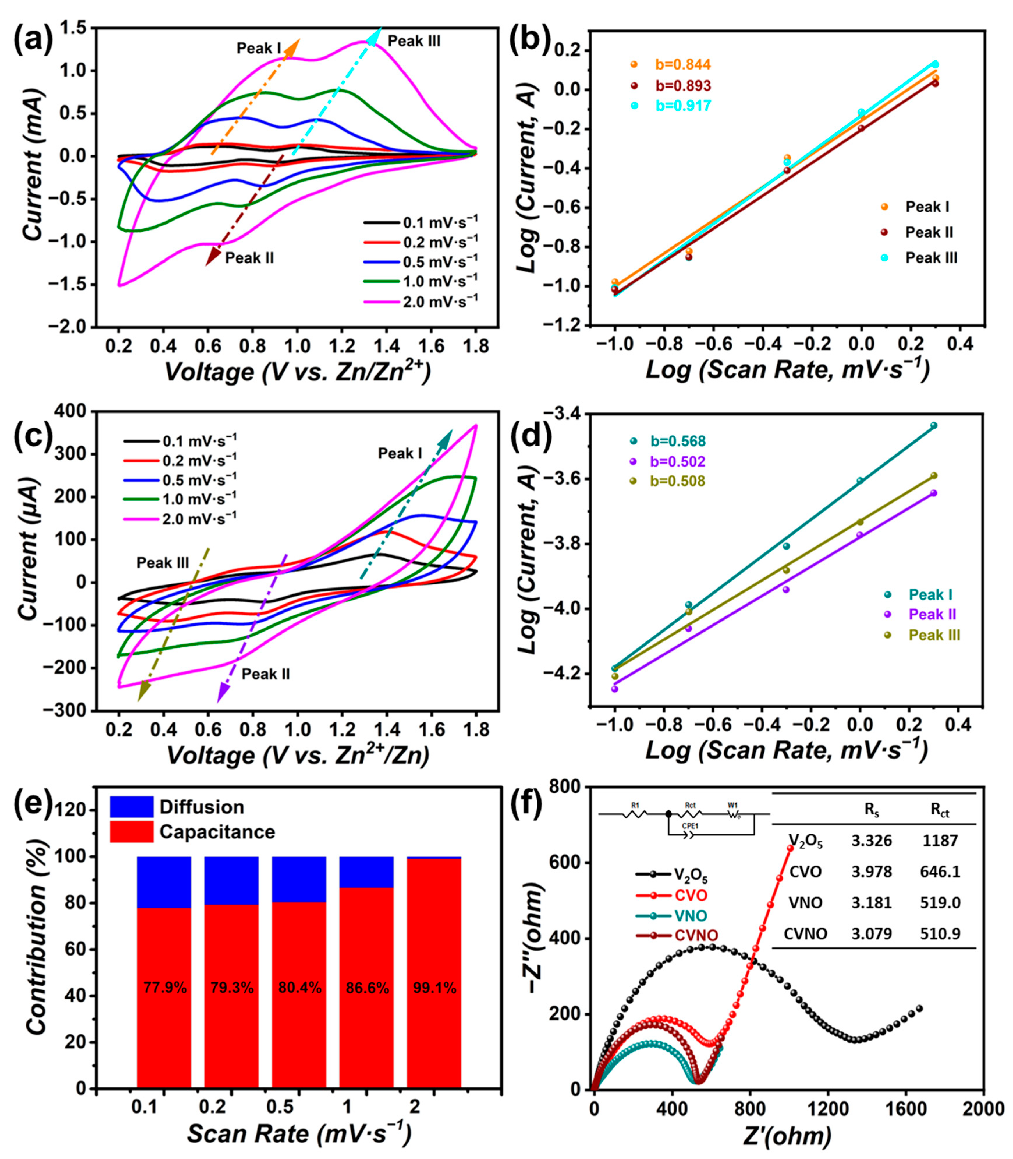
According to the GCD curves plotted at different current densities (Figure S9), it can be seen that as the current density increases, the voltage range of the charging and discharging process is gradually reduced, which is also part of the reason for the decrease in capacity at high current densities. In order to further explore the type of Zn2+ intercalation in the CVNO and VNO, we quantitatively separated the contributions of diffusion and capacitance to the material’s capacity by performing CV tests with different scan rates in the voltage range of 0.1~2.0 mV·s−1 (Figure 4a–d). Due to the effect of polarization, the peaks of the CV curve change in shape and shifts slightly at high scan rates. The relationship between current response and scan rates can be described using a simplified equation [36]:
i = avb
where i is the charge–discharge current, v is the scan rate, and a and b are coefficient parameters; b can be determined by the slope of the linear plot of log i vs. log v.
Typically, the Zn2+ ion intercalation process has a b value of 0.5 when controlled by diffusion and a b value of 1 when controlled by capacitance [37]. For the CVNO material, the calculated b values of the three typical peaks are 0.844, 0.893, and 0.917. This indicates that for the CVNO cathode, the intercalation is contributed by a combination of the Faraday process and the double-layer effect for zinc storage. However, in the VNO material without cation doping, the calculated b values of the three typical peaks are 0.568, 0.502, and 0.508. These results prove that the Zn2+ intercalation mechanism of VNO cathode is different from CVNO, which is diffusion-controlled. The layer structure of CVNO can provide a high specific surface area and a number of surface active sites, which is beneficial to the capacitance control process. The introduction of oxygen defects after nitridation will provide more convenient paths for Zn2+ insertion. Compared with original V2O5 and VNO, the introduction of Ca2+ can effectively reduce the charge transfer resistance by increasing the layer spacing and stabilizing the layer structure, which is more favorable for Zn2+ diffusion. However, it is generally believed that compared with the diffusion control process, the capacitance control process is more conducive to obtaining high rate performance [38]. This is also confirmed by the rate performance test.
Moreover, BET analysis was also carried out to investigate the specific surface areas of these materials (Table S3). The specific surface areas of the vanadium oxides obtained after ion doping are all larger than that of pristine V2O5. VNO exhibits a large specific surface area. It may be attributable to the small pores on the surface of VNO particles after nitridation. Although CVNO has a smaller specific area than VNO, it exhibits the best performance. This may be due to the synergistic effect of the introduction of calcium and nitrogen.
The current reactions at a specific potential can be considered as a combination of two mechanisms. Thus, two coefficients k1 and k2 are set for the diffusion-controlled Faraday current and the capacitor-controlled current, respectively [39]. The relationship between current and scan rate is:
i(V) = k1v + k2v1/2
The equation can be further transformed into:
i(V)/v1/2 = k1v1/2 + k2
where k1 corresponding to different potentials is calculated from the slope of the i(V)/v1/2 and v1/2 fitting line at different scan rates.
By determining k1v and k2v1/2, it is possible to quantify the contribution ratio of two effects at a specific potential. For the CVNO cathode material, the Faraday current and the capacitance current of the diffusion control were calculated using the above method, and the contribution percentage of the two currents at each scan rate is listed in the histogram (Figure 4e). The contribution of the capacitive current increases as the scan rate increases, indicating that the CVNO cathode has excellent charge transfer kinetics and thus exhibits excellent rate performance.
The Nyquist plots of V2O5, CVO, VNO, and CVNO are displayed in Figure 4f. The Nyquist plot consists of a semicircle in the high-frequency region and a sloping line in the low-frequency region [40]. The intercepts of the high-frequency semicircles on the x-axis indicate the series resistances (Rs), which are 3.326, 3.978, 3.181, and 3.079 Ω for V2O5, CVO, VNO, and CVNO, respectively. It may be because the introduction of the nitride phase improves the conductivity of VNO and CVNO compared to V2O5. The charge transfer resistances (Rct) for the materials are 1187, 646.1, 519.0, and 510.9 Ω, respectively. Comparing V2O5 and CVO, it can be found that the value of Rct has dropped a lot after modification by Ca2+. This can be attributed to the Ca2+ dopants increasing the layer spacing and stabilizing the structure, which is more conducive to the transmission of Zn2+. In addition, from the EIS test (Figure 4f), the series resistances (Rs) and the charge transfer resistances (Rct) of vanadium oxide doped with nitrogen are both lower than that of vanadium oxide without nitridation. This may be due to the doping of the nitride phase, which improves the conductivity of VNO and CVNO compared to V2O5. Additionally, the oxygen atom defects caused by nitrogen atom doping provide more sites for the diffusion of Zn2+ in the electrolyte. Both effects are reflected in CVNO, with CVNO having lower internal resistance and charge transfer resistance. As a result, CVNO exhibits the highest electrochemical performance of all samples.
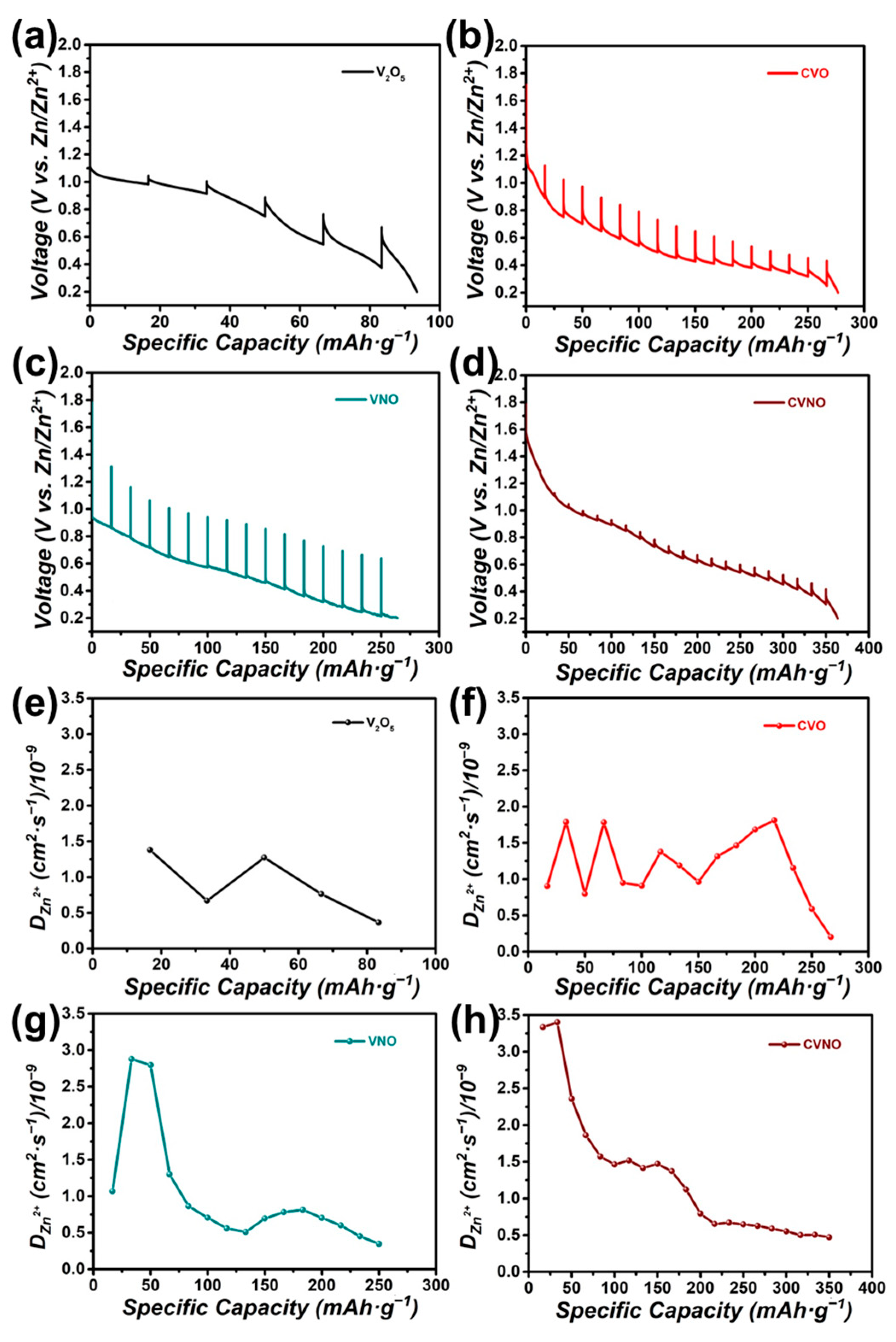
Finally, GITT was tested on the V2O5, CVO, VNO, and CVNO cathodes to explore the kinetics of Zn2+ diffusion in the voltage range of 0.2~1.8 V. During the GITT, a current impulse of 0.1 A·g−1 was exerted for 600 s, followed by a relaxation of 1800 s. The diffusion coefficient of Zn2+ in the material can be calculated from the following equation [41]:
D Z n 2 + = 4 π τ ( m B V M M B S ) 2 ( Δ E s Δ E τ ) 2   ( τ < < l 2 / D Z n 2 + )
where mB and MB are the mass and molecular weight of the active material, respectively; VM is the molar volume of the active material; S is the contact area between the electrolyte and the electrode; l is the Zn ion diffusion length; and ∆Es and ∆Eτ are the steady-state voltage change by the current pulse and the voltage change after subtracting the IR drop.
As shown in the discharge curves in Figure 5a–d, CVNO delivered the highest capacity, followed by VNO and CVO, and the lowest belonged to V2O5. The diffusion coefficients of Zn2+ (DZn2+) as a function of specific capacity were obtained from the GITT curve and are shown in Figure 5e–h. The calculated average DZn2+ values for V2O5, CVO, VNO, and CVNO in the discharge processes are about 8.90 × 10⁻¹⁰, 1.18 × 10⁻⁹, 1.26 × 10⁻⁹, and 1.28 × 10⁻⁹ cm2·S−1, respectively. This result shows that the anion- and cation-modified CVNO has both diffusion promotion mechanisms, of widening the interlayer spacing and introducing the defects, which have the greatest advantage in terms of Zn2+ diffusion kinetics.

4. Conclusions

In summary, V2O5 is modified by partially nitriding and cation doping, and then used as a cathode material for ZIBs. CVNO can reach a high capacity of 418.5 mAh·g−1 at 0.1 A·g−1, with retaining 81.2% at 2.0 A·g−1 after 500 cycles with good cycle stability. On the basis of not changing the overall crystal structure, the oxygen atoms are partially replaced to form defects, providing more sites for Zn2+ storage in the cathode material, which is more conducive to its diffusion and intercalation/deintercalation process. Moreover, the addition of nitrogen causes the VN phase to be formed in the material, which causes a certain conductivity improvement compared to a single vanadium oxide phase. In addition, it is found that cation doping can enhance the cycle performance of the electrode by stabilizing the interlayer structure, and further increase the capacity by expanding the layer spacing. We believe that anion/cation co-doping can provide a universal strategy for high-performance electrode materials for practical ZIBs.

Supplementary Materials

The following supporting information can be downloaded at: https://www.mdpi.com/article/10.3390/batteries9070352/s1. Figure S1: XRD image of the synthesized CVO powder; Figure S2: SEM image of (a) V2O5 powder and (b) VNO; Figure S3: (a) SEM image and (b) TEM image with element content of CVO; Figure S4: (a) TEM image, (b,c) HRTEM image, and (d) SAED image of the synthesized VNO powder; Figure S5: (a) SAED image and (b) HRTEM image of the synthesized CVO powder; Figure S6: The EDS elemental mappings of the synthesized VNO powder; Figure S7: The EDS elemental mappings of the synthesized CVO powder; Figure S8: The high-resolution XPS spectrum of Ca 2p of CVNO; Figure S9: GCD curves of CVNO at different current densities; Table S1: Electrochemical performance of relative works [7,8,19,20,22,23,33,42,43]; Table S2: Inductively coupled plasma optical emission spectroscopy (ICP-OES) characterization. The data is collected by analyzing the CVNO material; Table S3: The specific surface areas.

Author Contributions

Conceptualization, F.H., X.Z. and R.B.; methodology, F.H., X.Z. and R.B.; validation, R.B., S.T. and Z.S.; formal analysis, X.Z. and R.B.; investigation, X.Z. and R.B.; resources, R.B. and S.T.; data curation, X.Z. and R.B.; writing—original draft preparation, X.Z., R.B. and S.T.; writing—review and editing, F.H., L.W., Z.S. and J.L.; visualization, X.Z., R.B. and S.T.; supervision, F.H. and Z.S.; project administration, F.H.; funding acquisition, F.H., L.W. and J.L. All authors have read and agreed to the published version of the manuscript.

Funding

This research was funded by the Natural Science Foundation of China (No. 51072130, 51502045, and 21905202), Innovative Research in the University of Tianjin (TD13-5077), Developed and Applied Funding of Tianjin Normal University (135202XK1702), the Australian Research Council (ARC) through the Discovery Project (No. DP200100365), and Discovery Early Career Researcher Award (DECRA, No. DE170100871) program.

Data Availability Statement

The data presented in this research are available upon request from the corresponding authors.

Conflicts of Interest

The authors declare no conflict of interest.

References

  1. Kaveevivitchai, W.; Manthiram, A. High-capacity zinc-ion storage in an open-tunnel oxide for aqueous and nonaqueous Zn-ion batteries. J. Mater. Chem. A 2016, 4, 18737–18741. [Google Scholar] [CrossRef]
  2. Yu, P.; Zeng, Y.X.; Zhang, H.Z.; Yu, M.H.; Tong, Y.X.; Lu, X. Flexible Zn-Ion Batteries: Recent Progresses and Challenges. Small 2019, 15, 1804760. [Google Scholar] [CrossRef] [PubMed]
  3. Liu, S.; Kang, L.; Kim, J.M.; Chun, Y.T.; Zhang, J.; Jun, S.C. Recent Advances in Vanadium-Based Aqueous Rechargeable Zinc-Ion Batteries. Adv. Energy Mater. 2020, 10, 2000477. [Google Scholar] [CrossRef]
  4. Dong, L.B.; Yang, W.; Yang, W.; Li, Y.; Wu, W.J.; Wang, G.X. Multivalent metal ion hybrid capacitors: A review with a focus on zinc-ion hybrid capacitors. J. Mater. Chem. A 2019, 7, 13810–13832. [Google Scholar] [CrossRef]
  5. Hu, P.; Zhu, T.; Ma, J.X.; Cai, C.C.; Hu, G.W.; Wang, X.P.; Liu, Z.A.; Zhou, L.; Mai, L.Q. Porous V2O5 microspheres: A high-capacity cathode material for aqueous zinc-ion batteries. Chem. Commun. 2019, 55, 8486–8489. [Google Scholar] [CrossRef] [PubMed]
  6. Wang, X.; Ma, L.; Zhang, P.; Wang, H.; Li, S.; Ji, S.; Wen, Z.; Sun, J. Vanadium pentoxide nanosheets as cathodes for aqueous zinc-ion batteries with high rate capability and long durability. Appl. Surf. Sci. 2020, 502, 144207. [Google Scholar] [CrossRef]
  7. Li, R.; Zhang, H.; Zheng, Q.; Li, X. Porous V2O5 yolk–shell microspheres for zinc ion battery cathodes: Activation responsible for enhanced capacity and rate performance. J. Mater. Chem. A 2020, 8, 5186–5193. [Google Scholar] [CrossRef]
  8. Chen, L.L.; Yang, Z.H.; Huang, Y.G. Monoclinic VO2(D) hollow nanospheres with super-long cycle life for aqueous zinc ion batteries. Nanoscale 2019, 11, 13032–13039. [Google Scholar] [CrossRef]
  9. Cui, F.; Zhao, J.; Zhang, D.; Fang, Y.; Hu, F.; Zhu, K. VO2(B) nanobelts and reduced graphene oxides composites as cathode materials for low-cost rechargeable aqueous zinc ion batteries. Chem. Eng. J. 2020, 390, 124118. [Google Scholar] [CrossRef]
  10. Wang, L.L.; Huang, K.W.; Chen, J.T.; Zheng, J.R. Ultralong cycle stability of aqueous zinc-ion batteries with zinc vanadium oxide cathodes. Sci. Adv. 2019, 5, eaax4279. [Google Scholar] [CrossRef]
  11. Li, X.; Ma, L.; Zhao, Y.; Yang, Q.; Wang, D.; Huang, Z.; Liang, G.; Mo, F.; Liu, Z.; Zhi, C. Hydrated hybrid vanadium oxide nanowires as the superior cathode for aqueous Zn battery. Mater. Today Energy 2019, 14, 100361. [Google Scholar] [CrossRef]
  12. Liao, M.; Wang, J.; Ye, L.; Sun, H.; Wen, Y.; Wang, C.; Sun, X.; Wang, B.; Peng, H. A Deep-Cycle Aqueous Zinc-Ion Battery Containing an Oxygen-Deficient Vanadium Oxide Cathode. Angew. Chem. 2019, 59, 2273–2278. [Google Scholar] [CrossRef] [PubMed]
  13. Wei, T.Y.; Li, Q.; Yang, G.Z.; Wang, C.X. High-rate and durable aqueous zinc ion battery using dendritic V10O24· 12H2O cathode material with large interlamellar spacing. Electrochim. Acta 2018, 287, 60–67. [Google Scholar] [CrossRef]
  14. Li, Q.; Wei, T.; Ma, K.; Yang, G.; Wang, C. Boosting the Cyclic Stability of Aqueous Zinc-Ion Battery Based on Al-doped V10O24· 12H2O Cathode Materials. Acs Appl. Mater. Interfaces 2019, 11, 20888–20894. [Google Scholar] [CrossRef]
  15. Kundu, D.; Adams, B.D.; Duffort, V.; Vajargah, S.H.; Nazar, L.F. A high-capacity and long-life aqueous rechargeable zinc battery using a metal oxide intercalation cathode. Nat. Energy 2016, 1, 16119. [Google Scholar] [CrossRef]
  16. Yang, Y.Q.; Tang, Y.; Fang, G.Z.; Shan, L.T.; Guo, J.S.; Zhang, W.Y.; Wang, C.; Wang, L.B.; Zhou, J.; Liang, S.Q. Li+ intercalated V2O5·nH2O with enlarged layer spacing and fast ion diffusion as an aqueous zinc-ion battery cathode. Energy Environ. Sci. 2018, 11, 3157–3162. [Google Scholar] [CrossRef]
  17. Guo, X.; Fang, G.Z.; Zhang, W.Y.; Zhou, J.; Shan, L.T.; Wang, L.B.; Wang, C.; Lin, T.Q.; Tang, Y.; Liang, S.Q. Mechanistic Insights of Zn2+ Storage in Sodium Vanadates. Adv. Energy Mater. 2018, 8, 1801819. [Google Scholar] [CrossRef]
  18. Tang, B.Y.; Fang, G.Z.; Zhou, J.; Wang, L.B.; Lei, Y.P.; Wang, C.; Lin, T.Q.; Tang, Y.; Liang, S.Q. Potassium vanadates with stable structure and fast ion diffusion channel as cathode for rechargeable aqueous zinc-ion batteries. Nano Energy 2018, 51, 579–587. [Google Scholar] [CrossRef]
  19. Tang, B.Y.; Zhou, J.; Fang, G.Z.; Guo, S.; Guo, X.; Shan, L.T.; Tang, Y.; Liang, S.Q. Structural Modification of V2O5 as High-Performance Aqueous Zinc-Ion Battery Cathode. J. Electrochem. Soc. 2019, 166, A480–A486. [Google Scholar] [CrossRef]
  20. Jiang, H.; Zhang, Y.; Pan, Z.; Xu, L.; Zheng, J.; Gao, Z.; Hu, T.; Meng, C. Facile hydrothermal synthesis and electrochemical properties of (NH4)2V10O25·8H2O nanobelts for high-performance aqueous zinc ion batteries. Electrochim. Acta 2020, 332, 135506. [Google Scholar] [CrossRef]
  21. Jiang, H.; Zhang, Y.; Pan, Z.; Xu, L.; Zheng, J.; Gao, Z.; Hu, T.; Meng, C.; Wang, J. NH4V3O8·0.5H2O nanobelts with intercalated water molecules as a high performance zinc ion battery cathode. Mater. Chem. Front. 2020, 4, 1434–1443. [Google Scholar] [CrossRef]
  22. Xia, C.; Guo, J.; Li, P.; Zhang, X.X.; Alshareef, H.N. Highly Stable Aqueous Zinc-Ion Storage Using a Layered Calcium Vanadium Oxide Bronze Cathode. Angew. Chem. Int. Edit. 2018, 57, 3943–3948. [Google Scholar] [CrossRef]
  23. Ming, F.; Liang, H.; Lei, Y.; Kandambeth, S.; Eddaoudi, M.; Alshareef, H.N. Layered MgxV2O5·nH2O as Cathode Material for High-Performance Aqueous Zinc Ion Batteries. ACS Energy Lett. 2018, 3, 2602–2609. [Google Scholar] [CrossRef] [Green Version]
  24. Li, J.; McColl, K.; Lu, X.; Sathasivam, S.; Dong, H.; Kang, L.; Li, Z.; Zhao, S.; Kafizas, A.G.; Wang, R.; et al. Multi-Scale Investigations of δ-Ni0.25V2O5·nH2O Cathode Materials in Aqueous Zinc-Ion Batteries. Adv. Energy Mater. 2020, 10, 2000058. [Google Scholar] [CrossRef]
  25. Ma, L.; Li, N.; Long, C.; Dong, B.; Fang, D.; Liu, Z.; Zhao, Y.; Li, X.; Fan, J.; Chen, S.; et al. Achieving Both High Voltage and High Capacity in Aqueous Zinc-Ion Battery for Record High Energy Density. Adv. Funct. Mater. 2019, 29, 1906142. [Google Scholar] [CrossRef]
  26. Bian, R.L.; Song, D.; Si, W.P.; Zhang, T.; Zhang, Y.X.; Lu, P.Y.; Feng, H.; Liang, J. Carbon nanotubes@nickel cobalt sulfide nanosheets for high-performance supercapacitors. Chem. Electro. Chem. 2020, 17, 3663–3669. [Google Scholar] [CrossRef]
  27. Fang, G.Z.; Hang, S.Q.; Chen, Z.X.; Cui, P.X.; Zheng, X.S.; Pan, A.Q.; Lu, B.G.; Lu, X.H.; Zhou, J. Simultaneous Cationic and Anionic Redox Reactions Mechanism Enabling High-Rate Long-Life Aqueous Zinc-Ion Battery. Adv. Funct. Mater. 2019, 29, 1905267. [Google Scholar] [CrossRef]
  28. Ding, J.W.; Du, Z.G.; Li, B.; Wang, L.Z.; Wang, S.W.; Gong, Y.J.; Yang, S.B. Unlocking the Potential of Disordered Rocksalts for Aqueous Zinc-Ion Batteries. Adv. Mater. 2019, 31, 1904369. [Google Scholar] [CrossRef]
  29. Huang, K.; Bi, K.; Liang, C.; Lin, S.; Zhang, R.; Wang, W.J.; Tang, H.L.; Lei, M. Novel VN/C nanocomposites as methanol-tolerant oxygen reduction electrocatalyst in alkaline electrolyte. Sci. Rep. 2015, 5, 11351. [Google Scholar] [CrossRef] [Green Version]
  30. Zhong, Y.; Chao, D.L.; Deng, S.J.; Zhan, J.Y.; Fang, R.Y.; Xia, Y.; Wang, Y.D.; Wang, X.L.; Xia, X.H.; Tu, J.P. Confining Sulfur in Integrated Composite Scaffold with Highly Porous Carbon Fibers/Vanadium Nitride Arrays for High-Performance Lithium-Sulfur Batteries. Adv. Funct. Mater. 2018, 28, 1706391. [Google Scholar] [CrossRef]
  31. He, J.R.; Manthiram, A. Long-Life, High-Rate Lithium-Sulfur Cells with a Carbon-Free VN Host as an Efficient Polysulfide Adsorbent and Lithium Dendrite Inhibitor. Adv. Energy Mater. 2020, 10, 1903241. [Google Scholar] [CrossRef]
  32. Galesic, I.; Kolbesen, B.O. Formation of vanadium nitride by rapid thermal processing. Thin Solid Film. 1999, 349, 14–18. [Google Scholar] [CrossRef]
  33. Liu, W.; Dong, L.; Jiang, B.; Huang, Y.; Wang, X.; Xu, C.; Kang, Z.; Mou, J.; Kang, F. Layered vanadium oxides with proton and zinc ion insertion for zinc ion batteries. Electrochim. Acta 2019, 320, 134565. [Google Scholar] [CrossRef]
  34. Wang, X.W.; Wang, L.Q.; Zhang, B.; Feng, J.M.; Zhang, J.F.; Ou, X.; Hou, F.; Liang, J. A flexible carbon nanotube@V2O5 film as a high-capacity and durable cathode for zinc ion batteries. J. Energy Chem. 2021, 59, 126–133. [Google Scholar] [CrossRef]
  35. Zhang, N.; Dong, Y.; Jia, M.; Xu, B.; Wang, Y.Y.; Qiu, M.D.; Xu, J.Z.; Liu, Y.C.; Jiao, L.F.; Cheng, F.Y. Rechargeable aqueous Zn-V2O5 battery with high energy density and long cycle life. ACS Energy Lett. 2018, 3, 1366–1372. [Google Scholar] [CrossRef]
  36. Lindström, H.; Södergren, S.; Solbrand, A.; Rensmo, H.; Hjelm, J.; Hagfeldt, A.; Lindquist, S.-E. Li+ Ion Insertion in TiO2 (Anatase). 2. Voltammetry on Nanoporous Films. J. Phys. Chem. B 1997, 101, 7717–7722. [Google Scholar] [CrossRef]
  37. Wang, J.; Polleux, J.; Lim, J.; Dunn, B. Pseudocapacitive contributions to electrochemical energy storage in TiO2 (anatase) nanoparticles. J. Phys. Chem. C 2007, 111, 14925–14931. [Google Scholar] [CrossRef]
  38. Chao, D.L.; Zhu, C.R.; Yang, P.H.; Xia, X.H.; Liu, J.L.; Wang, J.; Fan, X.F.; Savilov, S.V.; Lin, J.Y.; Fan, H.J.; et al. Array of nanosheets render ultrafast and high-capacity Na-ion storage by tunable pseudocapacitance. Nat. Commun. 2016, 7, 12122. [Google Scholar] [CrossRef] [Green Version]
  39. Liu, T.C.; Pell, W.G.; Conway, B.E.; Roberson, S.L. Behavior of molybdenum nitrides as materials for electrochemical capacitors —Comparison with ruthenium oxide. J. Electrochem. Soc. 1998, 145, 1882–1888. [Google Scholar] [CrossRef]
  40. Xu, Y.H.; Zhu, Y.J.; Liu, Y.H.; Wang, C.S. Electrochemical Performance of Porous Carbon/Tin Composite Anodes for Sodium-Ion and Lithium-Ion Batteries. Adv. Energy Mater. 2013, 3, 128–133. [Google Scholar] [CrossRef]
  41. Zhang, N.; Cheng, F.Y.; Liu, Y.C.; Zhao, Q.; Lei, K.X.; Chen, C.C.; Liu, X.S.; Chen, J. Cation-Deficient Spinel ZnMn2O4 Cathode in Zn(CF3SO3) 2 Electrolyte for Rechargeable Aqueous Zn-Ion Battery. J. Am. Chem. Soc. 2016, 138, 12894–12901. [Google Scholar] [CrossRef] [PubMed]
  42. Shin, J.; Choi, D.S.; Lee, H.J.; Jung, Y.; Choi, J.W. Hydrated Intercalation for High-Performance Aqueous Zinc Ion Batteries. Adv. Energy Mater. 2019, 9, 1900083. [Google Scholar] [CrossRef]
  43. Zhang, L.; Miao, L.; Zhang, B.; Wang, J.; Liu, J.; Tan, Q.; Wan, H.; Jiang, J. A durable VO2(M)/Zn battery with ultrahigh rate capability enabled by pseudocapacitive proton insertion. J. Mater. Chem. A 2020, 8, 1731–1740. [Google Scholar] [CrossRef]
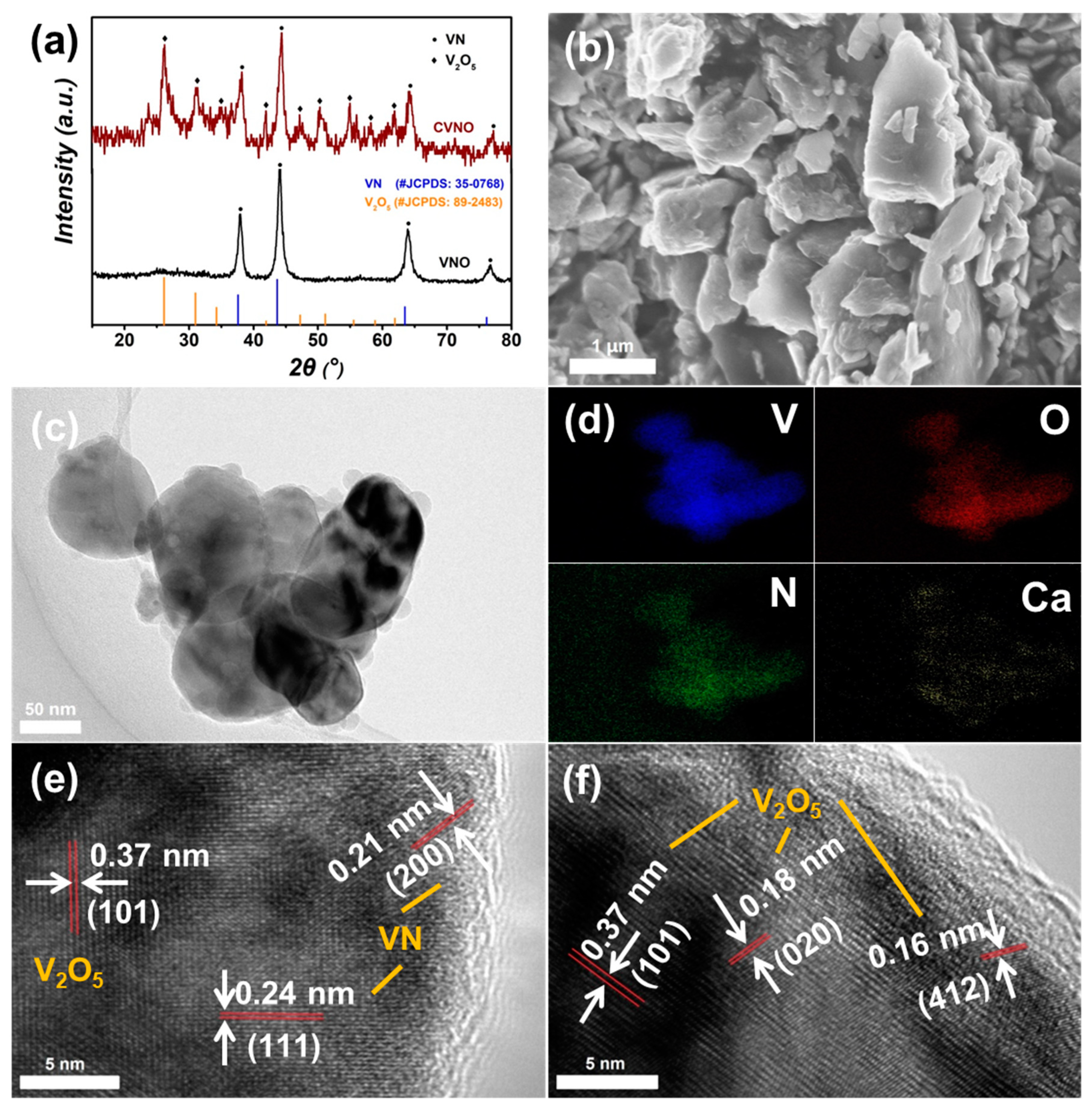
Figure 1. (a) XRD patterns, (b) SEM image, (c) TEM image, (d) the corresponding EDS elemental mappings, and (e,f) HRTEM images of the synthesized CVNO powder.
Batteries 09 00352 g001
Figure 2. The XPS survey spectrum of (a) VNO and (d) CVNO; high-resolution XPS spectrum of (b) N 1s and (c) V 2p of VNO, (e) N 1s and (f) V 2p of CVNO.
Batteries 09 00352 g002
Figure 3. (a) The first, third, and fifth CV curves of V2O5, CVO, VNO, and CVNO at a scan rate of 0.1 mV·s−1; (b) the GCD curves of CVNO at a current density of 0.1 A·g−1; (c) the rate performance of V2O5, CVO, VNO, and CVNO at different current densities; (d) cycling stability of V2O5, CVO, VNO, and CVNO at a current density of 1.0 or 2.0 A·g−1 for 500 cycles.
Batteries 09 00352 g003
Figure 4. CV curves of (a) CVNO and (c) VNO at different scan rates; log i vs. log v plots of three obvious peaks in CV curves of (b) CVNO and (d) VNO during the cycles; (e) normalized contribution ratio of capacitive capacities at different scan rates. (f) Nyquist plots of V2O5, CVO, VNO, and CVNO; the inset shows an equivalent circuit and the calculated values of Rs and Rct.
Batteries 09 00352 g004
Figure 5. Discharge curves in GITT tests of (a) V2O5, (b) CVO, (c) VNO, (d) CVNO and corresponding diffusivity coefficient (D) of Zn2+ in discharge processes of (e) V2O5, (f) CVO, (g) VNO, (h) CVNO.
Batteries 09 00352 g005
Disclaimer/Publisher’s Note: The statements, opinions and data contained in all publications are solely those of the individual author(s) and contributor(s) and not of MDPI and/or the editor(s). MDPI and/or the editor(s) disclaim responsibility for any injury to people or property resulting from any ideas, methods, instructions or products referred to in the content.