Abstract
All-solid-state lithium-sulfur batteries (ASSLSBs) are a promising next-generation battery technology. They exhibit high energy density, while mitigating intrinsic problems such as polysulfide shuttling and lithium dendrite growth that are common to liquid electrolyte-based batteries. Among the various types of solid electrolytes, solid polymer electrolytes (SPE) are attractive due to their superior flexibility and high safety. In this work, cross-linkable polymers composed of pentaerythritol tetraacrylate (PETEA) and tri(ethylene glycol) divinyl ether (PEG), are incorporated into sulfur–carbon composite cathodes to serve a dual function as both a binder and electrolyte, as a so-called catholyte. The influence of key parameters, including the sulfur–carbon ratio, catholyte content, and ionic conductivity of the electrolyte within the cathode on the electrochemical performance, was investigated. Notably, the sulfur composite cathode containing 30 wt% of the PETEA-PEG copolymer catholyte achieved a high initial discharge capacity of 1236 mAh g at a C-rate of 0.1 and 80 C.
1. Introduction
All-solid-state lithium–sulfur batteries (ASSLSBs) are attractive energy storage systems due to their high gravimetric energy density and safety, which makes them excellent candidates for mobile applications, especially in the transportation sector. Sulfur is a sustainable, low-cost, and abundant material, and thus is appealing as a potential replacement for current Li-ion battery cathode active materials. However, several challenges must be addressed before the practical applications of lithium–sulfur batteries (LSBs) can be achieved. Upon repeated LSB cycling, the sulfur cathode undergoes severe volume changes, leading to structural degradation of the cathode [1,2]. Additionally, short-chain polysulfides tend to accumulate on the cathode surface and these insulating polysulfides can increase the internal resistance of the cell, leading to a lowered coulombic efficiency [2]. Furthermore, the irreversible dissolution of polysulfides consumes sulfur, which can result in rapid capacity fading and a reduced overall battery performance [3]. Therefore, innovative strategies such as the redesign or replacement of cell components are necessary to overcome these limitations. In conventional LSBs, an ether-based liquid electrolyte, typically a mixture of 1,3-dioxolane (DOL) and 1,2-dimethoxyethane (DME) with dissolved ionic lithium compounds, is used, which is mainly responsible for the dissolution of polysulfides. However, this issue can be addressed by substituting the liquid electrolyte with a solid electrolyte. Moreover, the incorporation of a solid electrolyte into a lithium–sulfur battery can improve anode compatibility and increase energy density [3,4,5].
Solid polymer electrolytes (SPEs) have gained strong interest among other types of solid electrolytes because of their low cost, high flexibility, processability, and low interfacial resistance [6,7,8]. Among these, polyethylene oxide (PEO) has been extensively studied owing to the presence of ether functional groups in the molecular chain that can solvate Li ions. However, the crystalline region of PEO hinders the Li-ion transport mechanism, which necessitates a high operating temperature (∼80 C) to maintain adequate ionic conductivity. This high temperature, in turn, leads to mechanical instability in the electrolyte system [4]. Alternatively, cross-linked polymers are considered due to their amorphous nature and excellent mechanical stability, and the weak temperature dependency of the ionic conductivity, offering a potential solution to the challenges posed by PEO. The use of cross-linked pentaerythritol tetraacrylate (PETEA) is attractive as it is composed of acrylate groups that have a similar Li-ion carrier ability to the ether groups in PEO. Furthermore, the previously calculated binding energies between different functional groups and polysulfides have shown that ester groups exhibit a higher binding energy (1.26 eV) to polysulfides than ether groups (1.01 eV), which makes them better anchors for polysulfides and potentially impedes their migration to the Li-metal anode [9,10]. As reported in other studies, cross-linked PETEA was used in a lithium-sulfur battery as a gel polymer electrolyte (GPE), enhancing cycling stability and rate capacity compared to standard liquid electrolyte systems. The improvement was attributed to the immobilization of the polysulfides by the acrylate groups [11,12].
The integration of an SPE into the cathode composite as a so-called catholyte is crucial for the reliable transportation of Li ions and the overall operation of an all-solid-state battery (ASSB). To be performant, the catholyte needs to be compatible with the other materials present in the cathode, have low interfacial resistance, and be chemically stable. Moreover, with suitable mechanical properties, the catholyte can have a dual function and additionally act as a binder, hence allowing for the amount of inactive materials to be reduced. Researchers previously integrated catholytes into sulfur-based cathode composites but mainly investigated PEO or polyvinylidene fluoride (PVDF). For example, Eshetu et al. integrated PEO and PEO-PVDF with different lithium salts in sulfur cathode composites and investigated their cycling stability. The addition of PVDF to the PEO-based catholyte led to an enhanced cycling stability due to the decrease in the solubility of high-order polysulfides [13]. Park et al. used pentaerythritol tetrakis (3-mercaptopropionate) (PETT) to copolymerize with various monomers with several functional groups as a protective polymer layer on the sulfur cathode for a liquid-based LSB [10]. The ester functional groups anchored the polysulfides while the charge transfer at the electrolyte-electrode interface was not disrupted. In another study, PETEA was used as a cross-linked binder in a silicon (Si)-based anode for a Li-ion battery [14]. Similarly to sulfur-based cathodes, Si-based anodes experience a large volume expansion of Si of up to 300% during cycling [9,14]. A Si-anode with PETEA achieves a discharge capacity that is eight times higher than the Si-anode with a conventional PVDF binder. Additionally, its cycling stability was improved, indicating that cross-linked PETEA is able to effectively withstand internal stress forces. However, to date, no cathode with a PETEA catholyte has been reported.
In this work, all-solid-state sulfur cathodes with a pentaerythritol tetraacrylate (PETEA)-based polymer catholyte are developed. The cathodes were characterized with regard to their adhesion, electrical conductivity, and morphology. Furthermore, the electrochemical performance of the developed cathodes was assessed with coin cells composed of a Li metal anode and a standard polyethylene oxide (PEO) electrolyte separator. The discharge capacity and its dependence on parameters such as the carbon–sulfur ratio and the catholyte content were determined. Finally, the best cathode with the PETEA and tri(ethylene glycol) divinyl ether (PEG) copolymer catholyte was assembled with a hybrid electrolyte separator and a lithium metal anode to evaluate its electrochemical performance at room temperature (RT). The resulting ASSLSBs exhibited a specific discharge capacity of 859 mAh g.
2. Materials and Methods
2.1. Catholytes and Sulfur–Carbon Composite Cathodes
For the synthesis of the catholyte, pentaerythritol tetraacrylate (PETEA) monomer (Sigma Aldrich, Burlington, MA 01803, United States) and azobisisobutyronitrile (AIBN) (Sigma Aldrich, Burlington, MA 01803, United States) initiator are used and reacted via radical polymerization. The copolymer catholyte is a mixture of tri(ethylene glycol) divinyl ether (PEG) (Sigma Aldrich, Burlington, MA 01803, United States) and PETEA in a molar ratio of 12:1 and is referred to as PP12. Their molecular structure is presented in Figure 1a–c. For the cathode slurry preparation, sulfur (Zhongke JinYan (Beijing) Science And Technology Co., Ltd., ChaoYang, 100012 Beijing, China, 50–100 nm), and carbon black (C65, Imerys, 43 Quai de Grenelle, 75015 Paris, France) were mixed as dry powders before being added to dimethyl sulfoxide (DMSO) (Sigma Aldrich, Burlington, MA 01803, United States) solvent. The preparation of the cathode is described in the Supplementary Information, Section S1. The SPE separator was made of PEO (POLYOX WSR 205, DOW Chemical, Midland, MI 48674, United States) with an average molecular mass of Mw = 600,000 g mol and lithium bis(trifluoromethanesulfonyl)imide (LiTFSI) (HQ-115 3M, St. Paul, MN 55144-1000, United States) as the Li salt. The preparation process of the PEO-LiTFSI SPE separator is described in the Supplementary Information, Section S2.
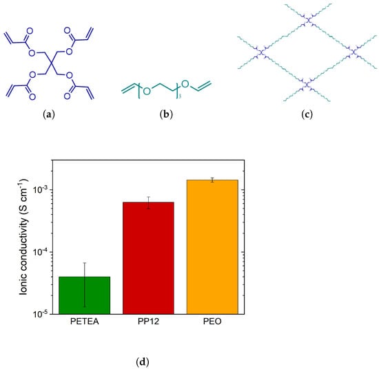
Figure 1.
Molecular structures of (a) PETEA, (b) PEG, and (c) cross-linked PEG:PETEA with a molar ratio of 12:1, and (d) ionic conductivity of PETEA-LiTFSI, PEG:PETEA (12:1)-LiTFSI, and PEO-LiTFSI SPEs measured at 80 C.
To evaluate the RT performance of the prepared cathodes, the PEO separator was substituted by a hybrid electrolyte separator that can operate at RT due to its higher ionic conductivity. The hybrid electrolyte separator was composed of PETEA, PEG, LiTFSI, and silane-functionalized Li7La3Zr2O12 (LLZO) filler particles. The synthesis process is described in a previous work by Jeon et al. [15]. The different catholytes were extensively characterized with regard to the thermal and chemical properties of PEO, PETEA, and PP12. From the investigation, it was observed that PETEA and PP12 were fully amorphous and stable at 80 C which is the cell cycling temperature.
2.2. Materials Characterization
The morphology of the cathode composites was investigated by scanning electron microscopy (SEM) (Helios G4 CX, FEI, Hillsboro, OR, United States) at 5 kV, and energy-dispersive X-ray spectroscopy (EDX) (Octane Elite-70, EDAX, Mahwah, NJ, United States) was conducted for elemental analysis. Before the SEM measurement, all samples were sputtered with platinum (4 nm, EM ACE600, Leica Microsystems, Wetzlar, Germany). The adhesive strength and electrical conductivity of the cathodes were measured using a customized set-up of a materials testing machine (Z020, Zwick GmbH & Co. KG, Ulm, Germany) coupled with a resistomat (Burster 2329) [16,17]. The properties of PETEA and PP12, such as an investigation of the degree of polymerization, were presented and discussed in our previous work [15]. Note that the in-situ polymerization of PETEA and PP12 did not reach 100% conversion and a small amount of monomer was still present after the overnight drying of the cathodes.
2.3. Electrochemical Characterization
The electrochemical performance of the materials was characterized via two types of electrochemical measurements using coin cells (2032, GELON, Dongguan, China) assembled under dry room conditions (dewpoint < C). The materials were characterized by electrochemical impedance spectroscopy (EIS) with a potentiostat (VSP-300, Biologic, Seyssinet-Pariset, France) within a frequency range of 4 MHz–100 mHz at 80 C. The SPEs were placed between two Cu foils (thickness of 20 m, Furukawa Electric Co., Tokyo, Japan). The calculated ionic conductivity of pure PEO-LiTFSI, pure PETEA-LiTFSI, and pure PP12-LiTFSI SPE separators was 1.4 × 10, 3.9 × 10 and 6.4 × 10 S cm, respectively (see Figure 1d). Their electrochemical performance and temperature dependency of the ionic conductivity were further discussed in a previous work by Jeon et al. [15].
The measured electrolyte resistance was used to determine the ionic conductivity of the SPEs with the electrolyte thickness d and the surface area A according to
For the cell-cycling tests, full cells composed of a lithium metal anode (thickness of 500 m, mass loading of 26.7 mg cm, Goodfellow), PEO-LiTFSI SPE (thickness of 150 m) as a separator, and a sulfur cathode with PETEA catholyte were cycled by a battery test system (Basytec) in a climate chamber (Binder GmbH) to control and ensure a homogeneous temperature. This investigation required the preparation of several cathodes with different compositions. For the catholyte content evaluation, the cathodes were composed of 40:20:40, 46.7:23.3:30, 53:27:20, 60:30:10 sulfur–carbon–catholyte weight ratios with mass loadings ranging from 0.9 to 1.38 mg cm. Additionally, the composition of the cathodes for the sulfur–carbon ratio study were 46.7:23.3:30, 49.7:20.3:30, and 60.2:9.8:30 sulfur–carbon–catholyte weight ratios with mass loadings ranging from 0.9 to 1.82 mg cm.
All cycling tests were performed at 80 C. The cycling procedure is described in Table 1. In the testing protocol, batteries are charged using a constant current–constant voltage (CC-CV) method. Initially, the cells are charged at a constant current until their voltage reaches 2.8 V. At this point, it is switched to a constant voltage phase, holding the cell voltage at 2.8 V for a specific duration. This approach ensures a complete charging of the cell while also preventing overcharging, thereby protecting the long-term stability and safety of the battery. The decreasing current during the constant voltage phase serves as a measure against overcharging, which can degrade battery performance over time and pose safety risks. For all electrochemical measurements, a minimum of three repeats were carried out, and the most representative curve was plotted for cell cycling. The coulombic efficiency of the different cycling tests is included in the Supplementary Information Figure S4. EIS measurements were conducted with the same biologic potentiostat and the resulting data were fitted with the corresponding equivalent circuit models (Supplementary Information, Section S3).

Table 1.
Cycling procedure with C-rate test.
3. Results and Discussion
3.1. Structural and Electrochemical Properties of Cathodes with Varied PETEA Catholyte Content
The formulation of the composite cathode is important to ensure its mechanical stability and enable good electrochemical performance. One of the components that strongly affects such properties is the catholyte, as it is responsible for carrying the Li-ions to and from the cathode active material and can influence sulfur utilization, reaction kinetics, and cycling stability. Moreover, the polymer used in the cathode composite in this work has the benefit of additionally acting as a binder. Therefore, the PETEA polymer is integrated into the cathodes as a catholyte, and its content is varied in increments of 10%, ranging from 10 to 40 wt%, while the remaining content consists of a sulfur and carbon composite. The sulfur–carbon ratio is therefore maintained at 66.66 and 33.33 wt%, respectively. First, the mechanical stability within the cathodes and of the cathode coating towards the current collector is quantified by measuring the adhesive strength (see Figure 2). The adhesive strength is an important factor to consider at the start of an electrode development, since the cathode coating has to withstand mechanical stresses during cycling due to the expansion and shrinkage of the electrochemically active material [17]. The large volume change of sulfur mainly causes disruption at the particle/catholyte/substrate interfaces, which strongly affects the cycle performance and stability. Empirically determined, an adhesive strength below 0.8 MPa [17] relates to either poor adhesion between the cathode coating and the current collector or weak cohesion within the composite. Figure 2 shows that the increase in catholyte content enhances the adhesion and cohesion of the components in the composite cathode. At a low catholyte content (10 and 20 wt%), the adhesive strength of the cathodes is below 0.8 MPa, suggesting poor mechanical stability. The cathodes prepared with 30 wt% and 40 wt% catholyte achieved a high adhesive strength of 1.28 MPa and 1.59 MPa, respectively. However, the adhesive strength measured for 40 wt% catholyte content is less repeatable, which could be an indication that the obtained cathodes are not uniform.
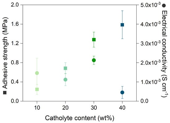
Figure 2.
Adhesive strength and electrical conductivity of cathodes with various PETEA catholyte contents.
Another aspect to consider when characterizing the cathode is the electrical conductivity, which relates to the electrode’s ability to carry electrons. The catholyte is an electrical insulator; thus, increasing its content should lead to a decrease in electrical conductivity. This correlation is observed for all catholyte contents, with the exception of 30 wt%, which led to the maximum observed electrical conductivity of 2.12 × 10 S cm (Figure 2). This behavior can be explained by the morphology of the cathode composite. The addition of different amounts of catholyte affects the distribution of carbon and sulfur in the slurry. This is corroborated by SEM images of the surface and cross-section of the cathodes (Figure 3). For cathodes containing 10 and 20 wt% catholyte, the cathode coatings (Figure 3a,b) are inhomogeneous, with sulfur agglomerates observed at the surface. Cracks are observed within the cathode composite, which may impede the formation of stable and continuous electron-conductive pathways, affecting the overall conductivity of the system. Based on the cross-section images in Figure 3a, the cathode composite at 10 wt% shows poor adhesion with signs of delamination from the current collector. The sulfur distribution of the cathode containing 30 wt% and 40 wt% catholyte content is more uniform (Figure 3c,d), as shown in the cross-section images.
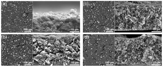
Figure 3.
SEM images of cathodes with (a) 10 wt%, (b) 20 wt%, (c) 30 wt% and (d) 40 wt% catholyte content of the surface (left) and their respective cross-section (right). Sulfur appears bright and carbon is dark in the images.
From the cross-section images, the increase in catholyte content of the cathode composite is shown to result in a denser structure, which ensures a stable network, resulting in improved mechanical properties of the pristine cathodes. As a consequence of the improved sulfur–carbon distribution and compact structure, the cathode composite has more available electron-conductive pathways. The integrity of the electrode–catholyte interface upon repeated cycling was investigated with EIS before and after cycling (Figure 4a,b). An equivalent circuit was used to simulate the EIS spectra (Figure S3). Both circuits are simplified representations of the processes occurring at the electrode–catholyte interface and at the interface of the bulk electrolyte separator. The Warburg element was omitted during the fitting, since the impedance measurement did not reach sufficiently low frequencies to resolve the contribution by diffusion. Before cycling, there is almost no difference in interfacial resistance at 10–30 wt% catholyte. However, at 40 wt% catholyte content, the semicircle located at a low frequency significantly increased, which suggests a significant increase in charge transfer resistance within the cathode. This is corroborated by the low electrical conductivity observed in Figure 2. With the exception of the cathode composite with a 40 wt% catholyte, for which the interfacial resistance strongly decreases after cycling (which is attributed to a structural degradation of the electrode in the 11th cycle with a coulombic efficiency close to 0% (see Figure S4a), a slight increase in interfacial resistance was generally observed. This result suggests the formation of an electrochemically stable interphase between the catholyte and the other components of the cathodes that do not deteriorate upon repeated cycling. The cycling stability and discharge capacity of the full cells with the respective cathodes is presented in Figure 5a. All cells achieve high initial discharge capacities of greater than 700 mAh g. However, the cathodes with the lowest catholyte content (10 and 20 wt%) reveal a higher initial discharge capacity of ∼1000 mAh g. This high initial capacity can be explained by looking at the surface morphology of the electrodes for 10 and 20 wt% catholyte content in Figure 3a,b. From the images, large sulfur particles are directly exposed on the surface of the electrode, interacting directly with the PEO separator and leading to high sulfur utilization. However, the earlier failure of the 10 and 20 wt% catholyte content cathodes is attributed to the higher amount of sulfur undergoing electrochemical reactions during the first cycles, enhancing volume expansion. This results in an increase in internal stresses within the cathode network, which ultimately induces the collapse of its structure, disrupting ionic and electronic pathways and additionally accelerating the shuttle effect. The prepared cathodes delivered good initial discharge capacities, which are comparable to previously reported studies, even though the ionic conductivity of the PETEA (3.9 × 10 S cm) is deemed too low to achieve such an electrochemical performance [13,18,19]. This suggests that some PEOs from the separator may infiltrate the cathode composite and help deliver such a high capacity.
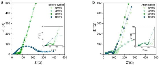
Figure 4.
Nyquist plot of cathodes with four different catholyte contents (a) before and (b) after cycling. The insets show a magnification of the high–frequency region of the graphs.
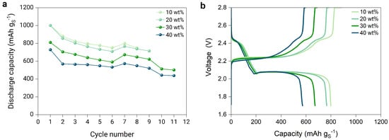
Figure 5.
(a) Discharge capacity of the full cells with lithium metal anode, PEO-based electrolyte separator, and sulfur cathodes composed of a 66.66:33.33 sulfur–carbon ratio and with a PETEA catholyte content from 10 to 40%, cycled according to the C-rate test protocol in Table 1, and (b) voltage profile at a C-rate of 0.05 of the cells.
The cathode with 30 wt% catholyte has the best cycling stability performance with an initial discharge capacity of 810 mAh g and capacity retention of >80% after nine cycles. For all samples, a rapid decline in discharge capacity is noticeable and is associated with the constant SEI formation at the surface of both electrodes and the polysulfide shuttle. The latter mechanism is further verified by the voltage profile of the respective cathodes (Figure 5b). The charge and discharge profiles of the PETEA-based sulfur cathode are similar to a liquid-based lithium–sulfur battery with a typical two-step reaction [20], consisting of a first plateau at higher voltages (2.4–2.5 V), and a second plateau (2.0–2.1 V), in which most of the capacity is obtained through the conversion of low-order polysulfides [3,21,22,23]. Similar voltage profiles were also observed when a standard PEO SPE separator was used at elevated temperatures [18,24]. The voltage profiles for the respective cathodes with various catholyte contents behave comparably regarding the voltage ranges at which the two plateaus appear (Figure 5b). However, the first plateau slightly shortens and drops earlier as the catholyte content increases. This behavior is revelatory of the limitations of the PETEA catholyte due to its poor ionic conductivity, as the first plateau is limited by catholyte access. If the PETEA catholyte were facilitating the Li-ion transport in the composite, the first plateau would become longer as the catholyte content increases. In addition, the second plateau shortens significantly when increasing the catholyte content due to the limited surface reaction, which results in a lower sulfur utilization.
3.2. Structural and Electrochemical Properties of Cathodes with Varied Sulfur–Carbon Ratio
Elemental sulfur is generally regarded as an insulator due to its low electrical conductivity. To create a functional cathode, optimal sulfur utilization can only be achieved with an ideal distribution of conductive carbon additives, which provide electron conductive pathways that are essential to electrochemical reactions. The effect of the sulfur–carbon (S:C) ratio on the cathode performance is investigate. Cathodes with three distinct S:C ratios (66.66:33.33, 71:29 and 86:14 wt%) were prepared. Each cathode contained 30 wt% catholyte, while the remaining 70 wt% consisted of sulfur–carbon. Thus, within the cathodes, the S:C:catholyte weight ratios were 46.7:23.3:30, 49.7:20.3:30, and 60.2:9.8:30. In all cases, the adhesive strength of the cathodes exceeded 1.1 MPa, indicating strong adhesion and cohesion within the composite cathodes. The cathode with an S:C ratio of 66.66:33.33 wt% exhibited the highest adhesive strength at 1.28 MPa (Figure 6a), while the 86:14 wt% S:C ratio possessed the lowest adhesive strength of 1.1 MPa. As stated, conductive carbon additives are essential to the formation of electron-conductive pathways; hence, the cathode containing the lowest amount of carbon (86:14 wt% S:C) reaches the lowest electrical conductivity of 3.24 × 10 S cm (Figure 6a). In contrast, the cathodes composed of 71:29 wt% and 66.66:33.33 wt% have a similar electrical conductivity, exceeding 2.0 × 10 S cm. Additionally, the surface morphology of the cathodes was investigated by SEM (Figure 7). The surface of the cathodes with 71:29 wt% and 66.66:33.33 wt% S:C ratio shows a homogeneous distribution of sulfur and carbon, and only small cracks are visible. However, the cathode with the highest amount of sulfur shows large cracks on the surface, as well as large sulfur aggregates. The presence of these sulfur particles disrupts the cathode structure and leads to interference with the electrical pathway.
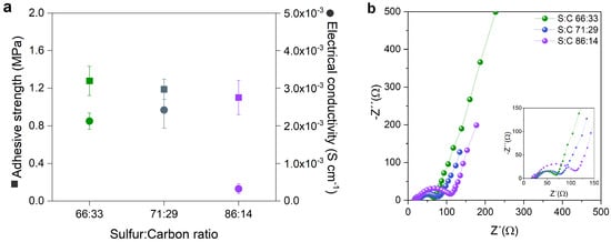
Figure 6.
(a) Adhesive strength and electrical conductivity, and (b) Nyquist plot of cathodes with three different S:C ratios (66.66:33.33, 71:29 and 86:14 wt%) with 30 wt% catholyte before cycling. The insets show a magnification of the high-frequency region of the graph.
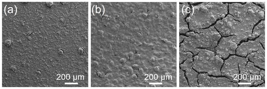
Figure 7.
SEM images of cathodes with a S:C ratio of (a) 66.66:33.33 wt%, (b) 71:29 and (c) 86:14 wt%.
The changes in the semicircles at low frequencies in the Nyquist plots of the cells (see Figure 6b) relate to the resistance charge transfer (RCT), and are indicative of the efficiency of the oxide-reduction processes and electron transfer through the electrode/electrolyte interface [25,26]. A low RCT value indicates an efficient charge/discharge process and a good interface contact inside the composite. The composite cathodes with 66.66: 33.33 wt% and 71:29 wt% S:C have low RCT values, with 93 and 96 , respectively, whereas the composite cathode with 86:14 wt% S:C has a RCT of 325 . Therefore, the RCT increases as the sulfur content in the cathode composite increases due to the insulating nature of the sulfur; however, this can also be affected by the inhomogeneous dispersion of sulfur and carbon.
Furthermore, the impact of the sulfur–carbon ratio on the electrochemical performance was investigated. Figure 8a compares the cycling rate and stability of the cathodes with different S:C ratios at 80 C. The cathode with 66.66:33.33 wt% achieved the highest initial discharge capacity of 810 mAh g, followed by 71:29 wt% with 451 mAh g and 86:14 wt% with 375 mAh g. These results indicate that an increase in carbon content leads to an enhancement of sulfur utilization. Although a high carbon content increases the capacity, it negatively affects the cycling stability. While the cathodes with 71:29 and 86:14 wt% cycled through the entire C-rate test and lasted for 92 cycles at 0.1 C, the cathode with 66.66:33.33 wt% only reached 11 cycles. Furthermore, the capacity retention after six cycles significantly decreases for 66.66:33.33 wt% with 83% compared to 97% for 71:29 wt% and 88% for 86:14 wt%. The decrease in carbon content in the cathode composite results in more sulfur becoming available to react with Li-ions, hence the high initial capacity observed for the cathode with 86:14 wt% S:C. This cathode experiences an important volume expansion, as well as the widespread formation of polysulfide as more sulfur participates in the electrochemical reaction, contributing to early cell failure. The effect of the carbon content and sulfur loading on sulfur utilization is also noticeable in the voltage profiles for the respective cathodes (see Figure 8b). The discharge curve for 86:14 wt% does not possess a first plateau at 2.4–2.5 V. This trend was previously observed for cathodes with high sulfur loading [27,28]. However, as the carbon content increases, both plateaus are becoming more defined. In the case of the cathode with 66.66:33.33 wt% S:C, both plateaus are pronounced, while for 71:29 wt% S:C, the first plateau is rather short. During discharge, the first plateau corresponds to the transition from S8 to soluble polysulfides of long-chain (Li2S8, Li2S6 or Li2S4) [29,30], while during the second plateau, the reduction in Li2S4 to insoluble short-chain polysulfides Li2S2/Li2S occurs. As the sulfur content increases, the first and the second discharge plateaus are shorter due to the isolated sulfur that is unable to contribute to the oxidation-reduction processes.
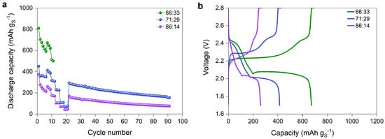
Figure 8.
(a) Discharge capacity of the full cells with lithium metal anode, PEO-based electrolyte separator, and sulfur cathodes composed of 30% of PETEA catholyte with three different S:C ratios (66.66:33.33, 71:29 and 86:14 wt%), cycled according to the C-rate test protocol in Table 1, and (b) the corresponding voltage profiles at the C-rate of 0.05 of the cells.
Additionally, the discharge behavior of the cathode composites with different S:C ratios is strongly affected by the C-rate (Figure S5). It is observed that, at low current densities (0.05 C & 0.1 C), the discharge curves for 66.66:33.33 wt% and 71:29 wt% S:C ratios display two plateaus, whereas the 86:14 wt% S:C ratio exhibits a short first plateau (2.4–2.5 V) (Figure S5). For 71:29 wt%, the first plateau disappears in all the curves for a C-rate of 0.25 and higher, and the second plateau starts at a lower voltage and is shortened (Figure S5b). However, at 0.25 C, 55% of the discharge capacity achieved at 0.05 C is reached. The plateaus disappear completely at 0.5 C and 1 C, indicating that sulfur was not accessible at these C-rates (see Supplementary Information, Section S5). This behavior is also observed for 86:14 wt%, in which the second plateau also fully disappeared from 0.5 C (Figure S5c). Moreover, the low carbon content resulted in a continuously dropping voltage curve at 0.25 C and this cathode only reaches 39% of the discharge capacity obtained at 0.05 C. The same effect regarding C-rate and S:C ratio was observed in a study by Brueckner et al. [27]. Furthermore, the C-rate has a significant impact on the cell cycle’s life and stability. In Figure S6b (Supplementary Information), it is observed that, at a higher C-rate (0.5 and 1 C), the cells terminated their cycling at an earlier period compared to the C-rate of 0.1. The cells with a 66.66:33.33 wt% S:C ratio can also be run for more than 50 cycles at a constant C-rate of 0.1. Therefore, even though the cathode composed of 66.66:33.33 wt% S:C ratio exhibited fewer testing cycles compared to other conditions, the promising performance observed in the initial cycles is sufficient to determine this composition as being superior in terms of capacity compared to the other systems. Therefore, the selected formulation for the following section will be composed of 66.66:33.33 wt% S:C ratio with 30 wt% catholyte.
3.3. Incorporation of PP12 Copolymer Catholyte and Comparison to PETEA Catholyte
The ionic conductivity of the catholyte in the cathode is important to ideally realize full utilization of the active material and ensure fast cell kinetics [4,31]. As previously observed in Figure 1d, the ionic conductivity of pure PETEA reaches 3.9 × 10⁻⁵ S cm−1 at 80 C, while the copolymer PP12 achieves 6.4 × 10⁻⁴ S cm−1. In this case, PP12 is employed as a catholyte and the cathode composition comprised S, C, and catholyte with a weight ratio of 46.7:23.3:30. During the cathode processing, no significant structural changes were observed, with both the PETEA-based and the PP12-based cathodes exhibiting small cracks and sulfur agglomerates of a similar size (Figures S8 and S9). Furthermore, the adhesive strength and electrical conductivity of both cathodes are also in a similar range (Figure 9a). Similar to PETEA, the copolymer provides a stable network, ensuring good adhesion to the current collector and cohesion within the electrolyte layer. From the cathode characterization results, it is possible to say that the structural integrity of the cathodes with PETEA and a copolymer is similar. However, the modification of the molecular structure of the catholyte with the PEG chains significantly changes the resistance within the cathode (Figure 9b). An additional semicircle in the medium-frequency range is observed when PP12 is used as a catholyte, suggesting an increase in resistance.
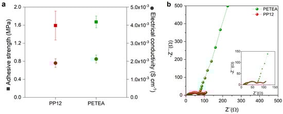
Figure 9.
(a) Adhesive strength and electrical conductivity, and (b) Nyquist plots determined for cathodes containing 30 wt% of the two tested catholyte types, PETEA and PP12, with an S:C ratio of 66.66:33.33. The insets show a magnification of the high-frequency region of the graph.
When comparing the electrochemical performance of the cathodes prepared with the two different catholytes, the discharge capacity results shown in Figure 10a and Figure S7 indicate a significant increase in specific capacity when using PP12 catholyte. A high initial discharge capacity of 1236 mAh g is exhibited with PP12 catholyte, which is higher than 400 mAh g more than that exhibited with PETEA catholyte. This can be attributed to the superior ionic conductivity of PP12 compared to PETEA. However, the cell stability is strongly affected by PP12, with a maximum of only five cycles achieved. To further understand the decreased cell stability, the voltage profiles of the first cycle are considered (Figure 10b). The first plateau is extended when PP12 catholyte is used compared to PETEA, indicating an enhanced sulfur utilization and, hence, a higher degree of sulfur conversion from elemental sulfur to higher-order polysulfides beginning with the first discharge. Consequently, the cathode with PP12 experiences more extensive volume changes, and the polysulfide shuttle is amplified. The increased volume changes induced by the higher sulfur conversion may result in the cathode material experiencing structural degradation, ultimately leading to a loss of contact between the active materials and the current collector. Furthermore, the intensified polysulfide shuttle could also exacerbate the side reactions between the polysulfides and the lithium anode, contributing to the formation of a thicker SEI layer, which is evidenced by the micro-peaks observed in the charge curves of the cells, attributed to SEI formation. To summarize, the optimal cell design for this investigation was obtained in a coin cell set-up, with a 500 m lithium metal foil, a PEO electrolyte separator and cathode formulation consisting of a sulfur-to-carbon ratio of from 66.66 to 33.33 and a PP12 catholyte content of 30 wt%. This formulation delivered the highest performance, achieving an initial discharge capacity of 1100 mAh g at a C-rate of 0.1 and 80 C.
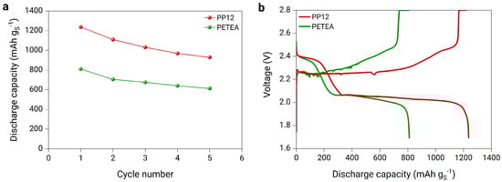
Figure 10.
(a) Discharge capacity of the full cells with lithium metal anode, PEO-based electrolyte separator, and sulfur cathodes composed of an S:C ratio of 66.66:33.33 and 30 wt% of two different catholytes, PP12 and PETEA cycled at a C-rate of 0.1, and (b) voltage profile at a C−rate of 0.05 after a formation cycle.
3.4. Room Temperature Performance
The PEO separator employed in the experiments discussed in the two previous sections is unsuitable for use at RT because of its inherently low ionic conductivity, which is caused by the crystalline regions forming within the material at lower temperatures. A minimum requirement of electrolyte separator for effective battery utilization should be of at least 10−4 S cm−1. Therefore, a previously developed hybrid electrolyte separator (HES) with an ionic conductivity of 1.13 × 10⁻³ S cm−1 at RT is chosen to investigate the electrochemical performance of the PP12 cathode at RT (Figure S10) [15]. The cycle test is conducted at a C-rate of 0.1 and 20 C, and the cell exhibits a discharge capacity of 859 mAh g at the second cycle, with a capacity retention of 9% after 50 cycles (Figure 11a). The voltage profiles of the cells reveal two voltage plateaus in the second cycle (Figure 11b). The voltage profile of the first cycle should be neglected due to the formation of the solid electrolyte interface (SEI). The slope between the first and second plateaus of the Li-HES-PP12 cell demonstrates a relatively gradual change, in contrast to the steeper slope observed for the Li-PEO-PP12 cell. However, the capacity of the cell substantially declines, and the upper discharge plateaus continuously shrink with increasing cycle numbers, indicating an irreversible loss of active material in the composite cathodes. EIS studies were performed to analyze impedance changes in cells before and after cycling. Figure S11 presents the Nyquist plots of the cell with a lithium metal anode, HSE separator, and PP12-based cathode before and after cycling, fitted with an equivalent circuit (see Figure S3). The intercept of the semicircle represents the ohmic interfacial resistance attributed to the electrolyte separator. The results show an increase in the interfacial resistance from 19.9 to 31.7 after cycling, suggesting that insulating polysulfide species may have accumulated in the electrolyte separator during repeated cycling and electrochemical reactions. Moreover, the diameter of the semicircle represents the charge transfer resistance. The charge transfer resistance of the cell before cycling (434.8 ) is higher than that after cycling (75.9 ), which is indicative of an improvement in the charge transfer kinetics of the cathode material, as demonstrated by the decreased resistance following cycling. This may be due to the enhanced cathode material surface properties resulting from electrolyte exposure during repeated cycling. Further investigation is needed to address the capacity fade of the cells, such as using more stable and efficient electrically conductive carbon materials, modifying the electrolyte composition, or optimizing the cell design. Additionally, more comprehensive studies are required to understand the underlying mechanisms of capacity fading and impedance changes in LSBs during cycling, which can offer valuable insights into the electrochemical performance and long-term stability mechanisms.
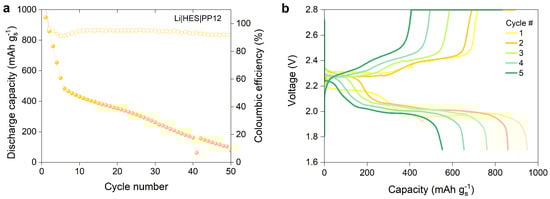
Figure 11.
(a) Discharge capacity of the full cell with lithium metal anode, hybrid electrolyte separator (HES), and PP12-based cathode (S:C ratio of 66.66:33.33, and 30 wt% of catholyte content) cycled at a C-rate of 0.1, and (b) their voltage profiles between 1–5 cycles.
4. Conclusions
Cathodes incorporating cross-linked PETEA catholytes were successfully developed for ASSLSBs. Extensive investigations were carried out on key cathode properties, including adhesion, electrical conductivity, and, most importantly, electrochemical performance. In situ-polymerized PETEA serves a dual function as both a catholyte and binder in the cathode composite. The catholyte content, sulfur–carbon ratio, and the type of catholyte were tailored by investigations. Among all cathodes, the best performance was achieved for the system with an S:C:catholyte ratio of 46.7:23.3:30, which exhibited an initial discharge capacity of 810 mAh g. Subsequently, another catholyte was examined to investigate the impact of the ionic conductivity of the catholyte on cycling performance. PETEA catholyte was replaced by a copolymer composed of PETEA and PEG (PP12). Pure PP12 exhibited an ionic conductivity of 6.4 × 10⁻⁴ S cm−1 at 80 C, an order of magnitude higher than of pure PETEA. The cathode with PP12 catholyte achieved an excellent performance and is, therefore, promising for further optimization. The cell with the PP12 cathode and a PEO-based separator attained an average initial discharge capacity of 1100 mAh g at 80 C. Moreover, the PP12 cathode was assembled with a hybrid electrolyte separator and lithium metal anode to evaluate its RT performance, resulting in an initial discharge capacity of 859 mAh g. Due to the simple design of the cathode, which did not involve the pretreatment of sulfur and carbon to form a composite or the use of multi-dimensional carbon structures, the shuttle effect likely played a significant role, leading to early failure during cycling. This work could be particularly relevant for the development of new polymer-based ASSLSBs, as it encourages a shift from conventional PEO and PVDF to unexplored polymers that offer more promising performance at lower temperatures.
5. Patents
E.J., A.J. and G.G. are authors on a patent related to this work submitted by Technische Universität Braunschweig (no. 102022204975.6, filed on 18 May 2022).
Supplementary Materials
The following supporting information can be downloaded at: https://www.mdpi.com/article/10.3390/batteries9070341/s1. Figure S1: Cathode processing steps. The gray boxes in the second row describe fixed parameters and materials, which were used for every cathode preparation; Figure S2: PEO-LiTFSI solid polymer electrolyte processing steps; Figure S3: Equivalent circuit used to fit EIS data; Figure S4: Coulombic efficiency and cycling results for coin cells with PEO electrolyte separator and with (a) various catholyte content, (b) different sulfur to carbon ratio, and (c) PP12-based cathode; Figure S5: Discharge voltage profile at different C-rates for different S: C ratios (a) 66.66:33.33 (b) 71:29, and (c) 86:14; Figure S6: Discharge capacity of the full cells with lithium metal anode, PEO-based electrolyte separator, and sulfur cathodes with the sulfur to carbon ratio of 66.66:33.33 and PETEA catholyte content of 30 wt%, three cells are cycled (a) with a C-rate test protocol in Table 1, and (b) at a constant C-rate of 0.1; Figure S7: Discharge capacity of (a) the cells with lithium metal anode, PEO-based electrolyte separator, and sulfur cathodes with the sulfur to carbon ratio of 66.66:33.33 and PP12 catholyte content of 30 wt%, three cells are cycled at a C-rate of 0.1 and (b) the discharge capacity of the cell # 3; Figure S8: SEM images of the surface of cathodes with (a) PETEA and (b) PP12 catholytes; Figure S9: Real images of stamped cathodes with PP12 and PETEA; Figure S10: Ionic conductivity of pure PETEA, PP12, PEO, and hybrid electrolyte (HE) separators at 20 C; Figure S11: Nyquist plots of cells with lithium metal anode, HES, and PP12 cathode at 20 C before and after cycling.
Author Contributions
Conceptualization, A.J.-F. and E.J.J.; methodology, A.J.-F., E.J.J. and S.K; validation, S.K.; investigation, S.K.; resources, A.J.-F. and G.G.; data curation, A.J.-F., E.J.J. and S.K.; writing—original draft preparation, A.J.-F., E.J.J. and S.K.; writing—review and editing, A.J.-F., E.J.J. and G.G.; visualization, A.J.-F., E.J.J. and S.K.; supervision, A.J.-F. and G.G.; project administration, A.J.-F. and G.G.; funding acquisition, A.J.-F. and G.G. All authors have read and agreed to the published version of the manuscript.
Funding
The authors gratefully acknowledge financial support from the Deutsche Forschungsgemeinschaft (DFG, German Research Foundation) under Germany’s Excellence Strategy EXC 2163/1 Sustainable and Energy Efficient Aviation Project ID 390881007, as well as the Ministry of Science and Culture of Lower Saxony within the “Forschungslinie MOBILISE”.
Data Availability Statement
All data needed to evaluate the outcome of this study are present in the paper and/or the Supplementary Information. Additional data related to this study may be requested from the authors.
Acknowledgments
We acknowledge the assistance of Daniela Scholz for the FTIR and TGA measurements.
Conflicts of Interest
All authors declare no conflict of interest.
References
- Shaibani, M.; Mirshekarloo, M.S.; Singh, R.; Easton, C.D.; Cooray, M.C.D.; Eshraghi, N.; Abendroth, T.; Dörfler, S.; Althues, H.; Kaskel, S.; et al. Expansion-tolerant architectures for stable cycling of ultrahigh-loading sulfur cathodes in lithium-sulfur batteries. Sci. Adv. 2020, 6, eaay2757. [Google Scholar] [CrossRef] [PubMed]
- Waluś, S.; Offer, G.; Hunt, I.; Patel, Y.; Stockley, T.; Williams, J.; Purkayastha, R. Volumetric expansion of Lithium-Sulfur cell during operation—Fundamental insight into applicable characteristics. Energy Storage Mater. 2018, 10, 233–245. [Google Scholar] [CrossRef]
- Song, M.K.; Cairns, E.J.; Zhang, Y. Lithium/sulfur batteries with high specific energy: Old challenges and new opportunities. Nanoscale 2013, 5, 2186–2204. [Google Scholar] [CrossRef] [PubMed]
- Zhao, Q.; Stalin, S.; Zhao, C.Z.; Archer, L.A. Designing solid-state electrolytes for safe, energy-dense batteries. Nat. Rev. Mater. 2020, 5, 229–252. [Google Scholar] [CrossRef]
- Goodenough, J.B.; Park, K.S. The Li-ion rechargeable battery: A perspective. J. Am. Chem. Soc. 2013, 135, 1167–1176. [Google Scholar] [CrossRef]
- Qiang, L.; Xiao, S.; Daxian, C.; Ying, W.; Pengcheng, L.; Hongli, Z. Versatile Electrospinning for Structural Designs and Ionic Conductor Orientation in All-Solid-State Lithium Batteries. Electrochem. Energy Rev. 2022, 5, 18. [Google Scholar] [CrossRef]
- Bandyopadhyay, S.; Gupta, A.; Srivastava, R.; Nandan, B. Bio-inspired design of electrospun poly(acrylonitrile) and novel ionene based nanofibrous mats as highly flexible solid state polymer electrolyte for lithium batteries. Chem. Eng. J. 2022, 440, 135926. [Google Scholar] [CrossRef]
- Chiu, L.L.; Chung, S.H. Composite gel-polymer electrolyte for high-loading polysulfide cathodes. J. Mater. Chem. A 2022, 10, 13719–13726. [Google Scholar] [CrossRef]
- Seh, Z.W.; Zhang, Q.; Li, W.; Zheng, G.; Yao, H.; Cui, Y. Stable cycling of lithium sulfide cathodes through strong affinity with a bifunctional binder. Chem. Sci. 2013, 4, 3673–3677. [Google Scholar] [CrossRef]
- Park, K. Trapping lithium polysulfides of a Li-S battery. Energy Environ. Sci. 2015, 10, 147–154. [Google Scholar] [CrossRef]
- Judez, X.; Martinez-Ibañez, M.; Santiago, A.; Armand, M.; Zhang, H.; Li, C. Quasi-solid-state electrolytes for lithium sulfur batteries: Advances and perspectives. J. Power Sources 2019, 438, 226985. [Google Scholar] [CrossRef]
- Liu, M.; Zhou, D.; He, Y.B.; Fu, Y.; Qin, X.; Miao, C.; Du, H.; Li, B.; Yang, Q.H.; Lin, Z.; et al. Novel gel polymer electrolyte for high-performance lithium-sulfur batteries. Nano Energy 2016, 22, 278–289. [Google Scholar] [CrossRef]
- Fang, R.; Xu, H.; Xu, B.; Li, X.; Li, Y.; Goodenough, J.B. Reaction Mechanism Optimization of Solid-State Li–S Batteries with a PEO-Based Electrolyte. Adv. Funct. Mater. 2021, 31, 2001812. [Google Scholar] [CrossRef]
- Jang, S.Y.; Han, S.H. Fabrication of Si negative electrodes for Li-ion batteries (LIBs) using cross-linked polymer binders. Sci. Rep. 2016, 6, 38050. [Google Scholar] [CrossRef]
- Jeon, E.J.; Jean-Fulcrand, A.; Kwade, A.; Garnweitner, G. A Room-Temperature High Performance All-Solid-State Lithium-Sulfur Battery Enabled by a Cross-Linked Copolymer@Ceramic Hybrid Solid Electrolyte. Nano Energy 2022, 104, 107912. [Google Scholar] [CrossRef]
- Haselrieder, W.; Ivanov, S.; Tran, H.Y.; Theil, S.; Froböse, L.; Westphal, B.; Wohlfahrt-Mehrens, M.; Kwade, A. Influence of formulation method and related processes on structural, electrical and electrochemical properties of LMS/NCA-blend electrodes. Prog. Solid State Chem. 2014, 42, 157–174. [Google Scholar] [CrossRef]
- Haselrieder, W.; Westphal, B.; Bockholt, H.; Diener, A.; Höft, S.; Kwade, A. Measuring the coating adhesion strength of electrodes for lithium-ion batteries. Int. J. Adhes. Adhes. 2015, 60, 1–8. [Google Scholar] [CrossRef]
- Eshetu, G.G.; Judez, X.; Li, C.; Martinez-Ibañez, M.; Gracia, I.; Bondarchuk, O.; Carrasco, J.; Rodriguez-Martinez, L.M.; Zhang, H.; Armand, M. Ultrahigh Performance All Solid-State Lithium Sulfur Batteries: Salt Anion’s Chemistry-Induced Anomalous Synergistic Effect. J. Am. Chem. Soc. 2018, 140, 9921–9933. [Google Scholar] [CrossRef]
- Marmorstein, D.; Yu, T.H.; Striebel, K.A.; Mclarnon, F.R.; Hou, J.; Cairns, E.J. Electrochemical performance of lithiumrsulfur cells with three differentpolymer electrolytes. J. Power Sources 2000, 89, 219–226. [Google Scholar] [CrossRef]
- Su, Y.S.; Fu, Y.; Cochell, T.; Manthiram, A. A strategic approach to recharging lithium-sulphur batteries for long cycle life. Nat. Commun. 2013, 4, 2985. [Google Scholar] [CrossRef]
- Li, C.; Zhang, H.; Otaegui, L.; Singh, G.; Armand, M.; Rodriguez-Martinez, L.M. Estimation of energy density of Li-S batteries with liquid and solid electrolytes. J. Power Sources 2016, 326, 1–5. [Google Scholar] [CrossRef]
- Kolosnitsyn, V.S.; Kuzmina, E.V.; Karaseva, E.V. On the reasons for low sulphur utilization in the lithium-sulphur batteries. J. Power Sources 2015, 274, 203–210. [Google Scholar] [CrossRef]
- Risse, S.; Härk, E.; Kent, B.; Ballauff, M. Operando Analysis of a Lithium/Sulfur Battery by Small-Angle Neutron Scattering. ACS Nano 2019, 13, 10233–10241. [Google Scholar] [CrossRef] [PubMed]
- Hong, S.; Wang, Y.; Kim, N.; Lee, S.B. Polymer-based electrolytes for all-solid-state lithium–sulfur batteries: From fundamental research to performance improvement. J. Mater. Sci. 2021, 56, 8358–8382. [Google Scholar] [CrossRef]
- Wei, C.; Han, Y.; Liu, H.; Gan, R.; Li, Q.; Wang, Y.; Hu, P.; Ma, C.; Shi, J. Advanced lithium–sulfur batteries enabled by a SnS2-Hollow carbon nanofibers Flexible Electrocatalytic Membrane. Carbon 2021, 184, 1–11. [Google Scholar] [CrossRef]
- Sångeland, C.; Hernández, G.; Brandell, D.; Younesi, R.; Hahlin, M.; Mindemark, J. Dissecting the Solid Polymer Electrolyte–Electrode Interface in the Vicinity of Electrochemical Stability Limits. ACS Appl. Mater. Interfaces 2022, 14, 28716–28728. [Google Scholar] [CrossRef]
- Brueckner, J.; Thieme, S.; Grossmann, H.T.; Doerfler, S.; Althues, H.; Kaskel, S. Lithium-sulfur batteries: Influence of C-rate, amount of electrolyte and sulfur loading on cycle performance. J. Power Sources 2014, 268, 82–87. [Google Scholar] [CrossRef]
- Erisen, N.; Eroglu, D. Modeling the discharge behavior of a lithium-sulfur battery. Int. J. Energy Res. 2020, 44, 10599–10611. [Google Scholar] [CrossRef]
- Cuisinier, M.; Cabelguen, P.E.; Evers, S.; He, G.; Kolbeck, M.; Garsuch, A.; Bolin, T.; Balasubramanian, M.; Nazar, L.F. Sulfur Speciation in Li–S Batteries Determined by Operando X-ray Absorption Spectroscopy. J. Phys. Chem. Lett. 2013, 4, 3227–3232. [Google Scholar] [CrossRef]
- Zheng, D.; Liu, D.; Harris, J.B.; Ding, T.; Si, J.; Andrew, S.; Qu, D.; Yang, X.Q.; Qu, D. Investigation of the Li–S Battery Mechanism by Real-Time Monitoring of the Changes of Sulfur and Polysulfide Species during the Discharge and Charge. ACS Appl. Mater. Interfaces 2017, 9, 4326–4332. [Google Scholar] [CrossRef]
- Randau, S.; Weber, D.A.; Kötz, O.; Koerver, R.; Braun, P.; Weber, A.; Ivers-Tiffée, E.; Adermann, T.; Kulisch, J.; Zeier, W.G.; et al. Benchmarking the performance of all-solid-state lithium batteries. Nat. Energy 2020, 5, 259–270. [Google Scholar] [CrossRef]
Disclaimer/Publisher’s Note: The statements, opinions and data contained in all publications are solely those of the individual author(s) and contributor(s) and not of MDPI and/or the editor(s). MDPI and/or the editor(s) disclaim responsibility for any injury to people or property resulting from any ideas, methods, instructions or products referred to in the content. |
© 2023 by the authors. Licensee MDPI, Basel, Switzerland. This article is an open access article distributed under the terms and conditions of the Creative Commons Attribution (CC BY) license (https://creativecommons.org/licenses/by/4.0/).